EP4008946B1 - Connecteur doté d'un pilote guidé - Google Patents
Connecteur doté d'un pilote guidé Download PDFInfo
- Publication number
- EP4008946B1 EP4008946B1 EP21211874.9A EP21211874A EP4008946B1 EP 4008946 B1 EP4008946 B1 EP 4008946B1 EP 21211874 A EP21211874 A EP 21211874A EP 4008946 B1 EP4008946 B1 EP 4008946B1
- Authority
- EP
- European Patent Office
- Prior art keywords
- pilot
- connector
- receptacle
- final position
- legs
- Prior art date
- Legal status (The legal status is an assumption and is not a legal conclusion. Google has not performed a legal analysis and makes no representation as to the accuracy of the status listed.)
- Active
Links
- 230000014759 maintenance of location Effects 0.000 claims description 20
- 230000007704 transition Effects 0.000 claims description 11
- 238000003780 insertion Methods 0.000 description 15
- 230000037431 insertion Effects 0.000 description 15
- 230000008878 coupling Effects 0.000 description 10
- 238000010168 coupling process Methods 0.000 description 10
- 238000005859 coupling reaction Methods 0.000 description 10
- 230000013011 mating Effects 0.000 description 10
- 239000012530 fluid Substances 0.000 description 7
- 230000000717 retained effect Effects 0.000 description 6
- 238000000034 method Methods 0.000 description 4
- 230000008569 process Effects 0.000 description 4
- 238000009434 installation Methods 0.000 description 3
- 238000012986 modification Methods 0.000 description 2
- 230000004048 modification Effects 0.000 description 2
- 230000007480 spreading Effects 0.000 description 2
- 239000004952 Polyamide Substances 0.000 description 1
- 239000004954 Polyphthalamide Substances 0.000 description 1
- 229910000831 Steel Inorganic materials 0.000 description 1
- 239000007795 chemical reaction product Substances 0.000 description 1
- 239000000463 material Substances 0.000 description 1
- 230000002093 peripheral effect Effects 0.000 description 1
- 229920002647 polyamide Polymers 0.000 description 1
- 229920006375 polyphtalamide Polymers 0.000 description 1
- 238000007789 sealing Methods 0.000 description 1
- 239000010959 steel Substances 0.000 description 1
- 239000012815 thermoplastic material Substances 0.000 description 1
- 238000012795 verification Methods 0.000 description 1
Images


Classifications
-
- F—MECHANICAL ENGINEERING; LIGHTING; HEATING; WEAPONS; BLASTING
- F16—ENGINEERING ELEMENTS AND UNITS; GENERAL MEASURES FOR PRODUCING AND MAINTAINING EFFECTIVE FUNCTIONING OF MACHINES OR INSTALLATIONS; THERMAL INSULATION IN GENERAL
- F16L—PIPES; JOINTS OR FITTINGS FOR PIPES; SUPPORTS FOR PIPES, CABLES OR PROTECTIVE TUBING; MEANS FOR THERMAL INSULATION IN GENERAL
- F16L37/00—Couplings of the quick-acting type
- F16L37/08—Couplings of the quick-acting type in which the connection between abutting or axially overlapping ends is maintained by locking members
- F16L37/12—Couplings of the quick-acting type in which the connection between abutting or axially overlapping ends is maintained by locking members using hooks, pawls or other movable or insertable locking members
- F16L37/14—Joints secured by inserting between mating surfaces an element, e.g. a piece of wire, a pin, a chain
- F16L37/142—Joints secured by inserting between mating surfaces an element, e.g. a piece of wire, a pin, a chain where the securing element is inserted tangentially
- F16L37/144—Joints secured by inserting between mating surfaces an element, e.g. a piece of wire, a pin, a chain where the securing element is inserted tangentially the securing element being U-shaped
-
- F—MECHANICAL ENGINEERING; LIGHTING; HEATING; WEAPONS; BLASTING
- F16—ENGINEERING ELEMENTS AND UNITS; GENERAL MEASURES FOR PRODUCING AND MAINTAINING EFFECTIVE FUNCTIONING OF MACHINES OR INSTALLATIONS; THERMAL INSULATION IN GENERAL
- F16L—PIPES; JOINTS OR FITTINGS FOR PIPES; SUPPORTS FOR PIPES, CABLES OR PROTECTIVE TUBING; MEANS FOR THERMAL INSULATION IN GENERAL
- F16L37/00—Couplings of the quick-acting type
- F16L37/08—Couplings of the quick-acting type in which the connection between abutting or axially overlapping ends is maintained by locking members
- F16L37/084—Couplings of the quick-acting type in which the connection between abutting or axially overlapping ends is maintained by locking members combined with automatic locking
- F16L37/088—Couplings of the quick-acting type in which the connection between abutting or axially overlapping ends is maintained by locking members combined with automatic locking by means of a split elastic ring
- F16L37/0885—Couplings of the quick-acting type in which the connection between abutting or axially overlapping ends is maintained by locking members combined with automatic locking by means of a split elastic ring with access to the split elastic ring from a radial or tangential opening in the coupling
-
- F—MECHANICAL ENGINEERING; LIGHTING; HEATING; WEAPONS; BLASTING
- F16—ENGINEERING ELEMENTS AND UNITS; GENERAL MEASURES FOR PRODUCING AND MAINTAINING EFFECTIVE FUNCTIONING OF MACHINES OR INSTALLATIONS; THERMAL INSULATION IN GENERAL
- F16L—PIPES; JOINTS OR FITTINGS FOR PIPES; SUPPORTS FOR PIPES, CABLES OR PROTECTIVE TUBING; MEANS FOR THERMAL INSULATION IN GENERAL
- F16L37/00—Couplings of the quick-acting type
- F16L37/08—Couplings of the quick-acting type in which the connection between abutting or axially overlapping ends is maintained by locking members
- F16L37/084—Couplings of the quick-acting type in which the connection between abutting or axially overlapping ends is maintained by locking members combined with automatic locking
-
- F—MECHANICAL ENGINEERING; LIGHTING; HEATING; WEAPONS; BLASTING
- F16—ENGINEERING ELEMENTS AND UNITS; GENERAL MEASURES FOR PRODUCING AND MAINTAINING EFFECTIVE FUNCTIONING OF MACHINES OR INSTALLATIONS; THERMAL INSULATION IN GENERAL
- F16L—PIPES; JOINTS OR FITTINGS FOR PIPES; SUPPORTS FOR PIPES, CABLES OR PROTECTIVE TUBING; MEANS FOR THERMAL INSULATION IN GENERAL
- F16L37/00—Couplings of the quick-acting type
- F16L37/02—Couplings of the quick-acting type in which the connection is maintained only by friction of the parts being joined
-
- F—MECHANICAL ENGINEERING; LIGHTING; HEATING; WEAPONS; BLASTING
- F16—ENGINEERING ELEMENTS AND UNITS; GENERAL MEASURES FOR PRODUCING AND MAINTAINING EFFECTIVE FUNCTIONING OF MACHINES OR INSTALLATIONS; THERMAL INSULATION IN GENERAL
- F16L—PIPES; JOINTS OR FITTINGS FOR PIPES; SUPPORTS FOR PIPES, CABLES OR PROTECTIVE TUBING; MEANS FOR THERMAL INSULATION IN GENERAL
- F16L43/00—Bends; Siphons
- F16L43/008—Bends; Siphons made from plastic material
-
- F—MECHANICAL ENGINEERING; LIGHTING; HEATING; WEAPONS; BLASTING
- F16—ENGINEERING ELEMENTS AND UNITS; GENERAL MEASURES FOR PRODUCING AND MAINTAINING EFFECTIVE FUNCTIONING OF MACHINES OR INSTALLATIONS; THERMAL INSULATION IN GENERAL
- F16L—PIPES; JOINTS OR FITTINGS FOR PIPES; SUPPORTS FOR PIPES, CABLES OR PROTECTIVE TUBING; MEANS FOR THERMAL INSULATION IN GENERAL
- F16L47/00—Connecting arrangements or other fittings specially adapted to be made of plastics or to be used with pipes made of plastics
- F16L47/06—Connecting arrangements or other fittings specially adapted to be made of plastics or to be used with pipes made of plastics with sleeve or socket formed by or in the pipe end
- F16L47/12—Connecting arrangements or other fittings specially adapted to be made of plastics or to be used with pipes made of plastics with sleeve or socket formed by or in the pipe end with additional locking means
-
- F—MECHANICAL ENGINEERING; LIGHTING; HEATING; WEAPONS; BLASTING
- F16—ENGINEERING ELEMENTS AND UNITS; GENERAL MEASURES FOR PRODUCING AND MAINTAINING EFFECTIVE FUNCTIONING OF MACHINES OR INSTALLATIONS; THERMAL INSULATION IN GENERAL
- F16L—PIPES; JOINTS OR FITTINGS FOR PIPES; SUPPORTS FOR PIPES, CABLES OR PROTECTIVE TUBING; MEANS FOR THERMAL INSULATION IN GENERAL
- F16L2201/00—Special arrangements for pipe couplings
- F16L2201/10—Indicators for correct coupling
-
- F—MECHANICAL ENGINEERING; LIGHTING; HEATING; WEAPONS; BLASTING
- F16—ENGINEERING ELEMENTS AND UNITS; GENERAL MEASURES FOR PRODUCING AND MAINTAINING EFFECTIVE FUNCTIONING OF MACHINES OR INSTALLATIONS; THERMAL INSULATION IN GENERAL
- F16L—PIPES; JOINTS OR FITTINGS FOR PIPES; SUPPORTS FOR PIPES, CABLES OR PROTECTIVE TUBING; MEANS FOR THERMAL INSULATION IN GENERAL
- F16L2201/00—Special arrangements for pipe couplings
- F16L2201/60—Identification or marking
Definitions
- the field relates to a connector for connecting a tube to a device. More particularly, this disclosure relates to a connector having a guided pilot for capturing the endform of a tube.
- a connector In fluid piping in which a tube, such as a pipe or a hose, is joined to another device such as a pump, tank or another tube, a connector may be used for joining the tube to the other device.
- the connector may have a tubular receptacle for receiving a tube.
- the tube may include an endform for snap engagement to enable quick connection with a retainer to provide locking relation between the tube and the connector.
- a wire retainer is often used that has a pair of engagement arms that extend through slots in the receptacle to clip endform in the connector.
- the connector may include a seal ring between an inner periphery of a socket in the connector and an outer periphery of the endform to provide a fluid-tight seal that prevents leaking. Insufficient insertion of the endform into the connector can permit the seal to lack engagement with the endform and the connector to leak.
- Fluid piping connectors may find use in the auto industry.
- the connector is often equipped with an indexing member to align with an indexing member on the endform to ensure that endform is inserted with the proper orientation.
- Several orientations between the endform and the connector are often applicable, multiplying the number of connectors that must be made available to serve all orientations.
- a wire retainer can be made of a material that is harder than the tube or an endform on the tube. As the endform of the tube is inserted into the connector, the inwardly biased retainer can scrape the endform of the tube to an extent that it prevents or inhibits a fluid tight seal facilitated by the seal ring.
- the wire retainer which is mounted to the connector housing has to be retained in a mounted position for snap-engaging with the annular engaging projection of the pipe.
- each engaging arm is bent over or inclined radially inward, for example, at a leading end thereof to define an engaging portion, and the engaging portion engages with an outer peripheral surface of the connector housing in a pull-out direction when the wire retainer is mounted to the connector housing.
- DE 20 2020 103 903 U1 discloses a connector for connecting two fluid-conducting elements, with a female plug-in part and a male plug-in part that can be inserted into the female plug-in part, wherein a retainer is hooked up to the female plug-in part, and can be used to fix the male plug-in part to the female plug-in part.
- the female plug-in part has at least one verification element, in particular in the form of a code, which in the unfixed state is unreadable or incomplete.
- the known connectors often have the disadvantage that the male plug-in part fixing the female plug-in retainer is difficult to install requiring a considerable amount of force, to position it into its fixed position.
- a further disadvantage of the known connectors is that the wire retainer is completely separated from the connector, in particular when it is transferred to an open position, and thus represents a component that may be lost.
- at least in some known connectors not always a functionally reliable and tight connection between the male plug-in part and female plug-in part may be realized.
- a first embodiment of this disclosure provides a connector having a guided pilot for capturing a tubing endform.
- the connector comprises a receptacle including pilot in a mounting position, the pilot including an indicator piece slidable from the mounting position to a final position and first and second guide members located in second and third channels on the receptacle. Each of the first and second guide members slidable in their respective channels from the mounting position to the final position.
- a retention clip having legs is urged into a spread condition during a transition between the mounting position and the final position. In the final position, the pilot is past the legs of the retention clip whereby the legs of the retention clip retract to a relaxed condition and the indicator piece is visibly located on the receptacle and the first and second guide members latch the pilot to the receptacle.
- an assembly of a connector and a tube comprising a receptacle including a pilot in a mounting position and slidable to a final position upon insertion of the tube into the receptacle, thereby urging legs of a retention clip into a spread condition while the pilot is sliding from the mounting position into the final position.
- First and second guide members attached to the pilot are located in second and third channels on the receptacle with each of the first and second guide members slidable in their respective channel from the mounting position to the final position.
- An indicator piece attached to the pilot is located in a first channel on the receptacle. The first and second guide members latch the pilot to the receptacle and the indicator piece becomes visibly positioned when the pilot slides past the legs of the retention clip permitting the legs of the retention clip to retract to a relaxed condition when the pilot is in the final position.
- a process for coupling a tube comprising inserting a tube into a female end of a receptacle to a mounting position that engages a pilot mounted in the receptacle.
- the pilot including an indicator piece and first and second guide members located in respective channels on the receptacle with the indicator piece not visible in the mounting position.
- the process further includes inserting the tube into the female end of the receptacle to cause the legs of a retention clip into a spread condition while the pilot is transitioning from the mounting position to a final position. The pilot is guided by the indicator piece and the guide members during the transition.
- the process also includes inserting the tube into the receptacle to a final position permitting the legs of the retention clip to retract to a relaxed condition and causing the indicator piece to become visible indicating that the tube is coupled to the receptacle.
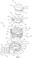
- FIG. 1 An exploded view of an example connector 10 for coupling a tube 12 to another device is illustrated in FIG. 1 .
- the other device may be another tube, or it could be a tank or a pump, for example.
- the tube 12 is partially shown in FIG. 1 and includes an endform 14 secured on an end of the tube 12.
- the tube 12 may be a hose, a pipe, or fluidly communicate with another device.
- the endform 14 may include a groove 13.
- the example connector 10 may be tubular defining a hollow passage through which a fluid may pass to or from the tube 12.
- the connector 10 may have an annular configuration made up of generally hollow cylindrical segments.
- the connector 10 comprises a receptacle 16 for receiving the endform 14 of the tube 12.
- the receptacle 16 may comprise two separate pieces.
- the first piece of the receptacle 16 is a socket 22.
- the socket 22 has a female end 18 and a coupling end 20.
- the female end 18 of the socket 22 receives the end of the tube 12.
- the socket 22 may receive the endform 14 of the tube 12 therein.
- the socket 22 includes an annular outer wall 26 surrounding the female end 18 defining an annulus.
- a latch 30 may be fashioned on the outer wall 26.
- a plurality of latches 30 may be fashioned on the outer wall 26.
- the latches may be rectangular and include a chamfered surface that extends obliquely outward from outer wall 26.
- An annular brim 37 extends about the lower periphery of outer wall 26 below latches 30.
- the brim 37 further includes a projection 38 extending vertically from brim.
- a plurality of projections 38 may be fashioned on the brim 38.
- the coupling end 20 may be for coupling the connector 10 to another device.
- the coupling end 20 may include a male stem 32 for mating with a receptacle of another device.
- the male stem 32 may include one or more barbed flanges 34 that can be friction fitted into another tube, for example, to couple the connector 10 to the other tube.
- fluid from the tube 12 can pass from the tube through the female end 18 of the socket 22 and through the male stem 32 of the coupling end 20 of the connector 10 and into the other tube installed over stem 32 or vice-versa.
- the coupling end 20 may extend at any convenient angle applicable to the intended use of receptacle 16, which means that the coupling end 20 can have a feature, where the male stem 32, can have a longitudinal axis that may extend from the axis of the female end 18 obliquely, defining an angle between coupling end 20 and female end 18 that is not equal to 180 degrees.
- the second piece of the receptacle 16 is a modular head 40.
- the modular head 40 has a mating end 42 with an annular outer wall 44 extending about the periphery of modular head 40 on its lower end.
- An opening 46 is located on the outer wall 44 extending through the outer wall.
- the outer wall 44 includes a projection receiver 48 adapted to receive therein an associated projection 38 when the modular head 40 is installed on socket 22.
- a plurality of openings 46 and projection receivers 48 may be fashioned about the periphery of outer wall 44 of mating end 42.
- the modular head 40 mates with the socket 22 to provide the receptacle 16.
- the mating end 42 of the modular head 40 is arranged to be inserted over the outer wall 26 of the socket 22.
- the mating of the modular head 40 to socket 22 is made by aligning a projection 38 with an associated projection receiver 48 and the modular head forced downward toward brim 37 to allow the chamfered portions of latches 30 to ride against the inside surface of the outer annular wall 44 until they are received within an associated opening 46, creating a snap-fit mechanical connection between the modular head 40 and socket 22.
- the mating end 42 of modular head 40 rests on brim 37 when the modular head 40 is fully inserted on socket 22 as can be best seen at FIG. 2 .
- the socket 22 and the modular head 40 may be separately molded of a thermoplastic material such as polyamide or polyphthalamide.
- the modular head 40 can be mated to the socket 22 in a plurality of relative orientations.
- the openings 46 and the plurality of latches 30 are located equidistant from each other around the periphery of modular head 40 outer wall 44 and socket outer wall 26. In other words, the latches 30 are at equivalent radial positions. Accordingly, the modular head 40 is adaptable to be mated to the receptacle 16 in a plurality of orientations.
- the projections 38 are located on the brim 37 at relative orientations, further facilitating the mating of the modular head 40 in a plurality of orientations. In the embodiment of FIG.
- the openings 46 and projection receivers 38 in the mating end 42 of modular head 40 are at four equidistant locations 90 degrees from each other.
- the latches 30 and projections 38 on socket 22 are also at four equidistant locations 90 degrees from each other. It will be well understood by those skilled in the art that due to the orientation of the latches 30 and openings 46 as well as the projections 38 and projections receivers 48, the connector 10 with a modular head 40 can be adaptable to be mounted in configurations that may have four different orientations between the connector 10 and the endform 14 of the tube 12.
- only one set of tooling must be fabricated to provide a connector 10 for four different orientations in an end product such as an automobile.
- modular head 40 may include an indexing member 50 thereon for alignment with an indexing form 52 on the endform 14 of the tube 12 to ensure proper orientation therebetween.
- the indexing member 50 on the modular head 40 may be a groove and the indexing form 52 a tab extending from endform 14.
- the tab 52 is arranged to be received in the groove 50 to ensure proper alignment while inserting the endform 14 into the modular head 40.
- the tab could be the indexing member 50 on the modular head 40 and the groove could be the indexing member 52 on the endform 14 of the tube 12.
- the endform may omit an indexing member 52, and it may also include an additional indexing member 53.
- the connector 10 includes a wire retainer 60 embracing the modular head 40.
- the wire retainer 60 has a u-shaped configuration comprising two opposed legs 62, 64 extending from a bight 66.
- the wire retainer 60 is retained on the modular head 40 when mated to the socket 22, but it could be retained directly on the socket 22.
- the wire retainer 60 may be made of steel.
- the bight 66 embraces an outer wall 68 of the modular head 40, however legs 62, 64 extend through slots in wall 68, permitting the legs to extend into the interior 72 of the modular head 40 when the retention clip 60 is in a relaxed condition.
- Each leg 62, 64 terminates in an upturned prong 61 which is assembled onto the modular head 40 by passing through a slot contiguous and orthogonal to the slots in wall 68.
- the modular head 40 permits various orientations with respect to the socket 22.
- the modular head 40 can also be rotatable to provide a desired positioning of features of the receptacle 16 in an installed context.
- the modular head 40 may be oriented with respect to the socket 22 to ensure access to the bight 66 among other equipment when installed.
- FIG. 1 and FIG. 3 illustrate an interior annular groove 74 in the socket 22.
- the annular groove 74 retains an elastomeric sealing assembly, for example an O-ring 76 in the groove 74.
- O-ring 76 squeezes around the endform 14 of the tube 12 and prevents leakage of fluid passing therethrough.
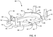
- FIG. 1 and FIG. 4 illustrate a further feature of the example connector 10.
- a pilot 80 is shown that is comprised of an annular crown piece.
- the pilot 80 includes an indicator piece 90 which may comprise a flat face 91 and a wedge-shaped latching member 92.
- the latching member 92 includes a chamfered surface that extends outward from the flat face 91 at a top portion thereof.
- the pilot 80 has a front inclined wall 88 that has an inner diameter and an outer diameter at a mating end 93 that is a greater diameter than an inner diameter at an engaging end 94.
- a similar wall 89 is located on a rear end of the pilot 80. Consequently, the inside and an outside surface of walls 88 and 89 taper inwardly along a direction of insertion.
- Pilot 80 further includes first and second L-shaped guide members 82 and 83 extending outward from rear outer wall 89.
- the pilot 80 further includes side members 95 and 98 that complete the side portions of pilot 80 between walls 88 and 89.
- Wall 88 terminates at a further member 97 on each side of the pilot 80.
- wall 89 terminates at a member 96 on each side of pilot 80.
- Leg 62 of wire retainer 60 is located between members 96 and 97 and side member 96.
- leg 63 of wire retainer 60 is located between members 96 and 97 and side member 98.
- Members 96 and 97 also aid in the installation of the endform 14 over wire retainer legs 62 and 64 and which will be more fully explained later.
- the pilot 80 is mounted into the modular head 40 and becomes a part of the receptacle 16 upon mating of socket 22 and the modular head 40.
- the pilot is installed in the modular head 40 with indicator piece 90 accepted into a first channel 55 formed on one end of modular head 40.
- each guide leg 82 and 83 is arranged to be accepted into an associated second and third channel 56 and 58 respectively, formed on another end of modular head 40 opposite from channel 55. Locations of the first 55, second 56 and third 58 channels can best be seen at FIG. 1 and FIG. 3 .
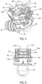
- FIG. 5 illustrates in an isometric view the pilot 80 installed in modular head 40 in a mounting position.
- the mounting position being the position of the pilot 80 before insertion of the endform 14 into modular head 40 of receptacle 16.
- the indicator piece 90 is installed into channel 55 with latch 92 accepted and retained in a first opening 100.
- pilot legs 82 and 83 are installed in their associated second and third channels 56 and 58.
- Channels 56 and 58 include openings along the back wall of each channel 56 and 58 allowing end portions 84 and 85 to extend outward of the channel openings.
- the top surfaces 110 and 120 of legs 82, 83 rest against a bottom surface of a first rib member 130.
- Rib member 130 extends from a rear portion of modular head 40.
- a friction fit is exerted between the chamfered surfaces of end portions 84 and 85 against a second rib member 135 located below and oriented parallel with first rib member 130.
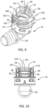
- the pilot 80 is slidable from the mounting position shown in FIG. 7 to a final position shown in FIG. 8 . Insertion of the endform 14 of the tube 12 into the modular head 40 of the receptacle 16 results in the endform 14 engaging the pilot 80 to transition the pilot 80 from the mounting position to the final position.
- the inner diameter of the pilot 80 at the engaging end 94 may be larger than the outer diameter d o of the endform 14 to allow a terminal end 102 of the endform to pass through the inner diameter of the pilot 80 without moving the pilot upon insertion.
- the terminal end 102 of the endform 14 extends into the socket 22 and is arranged to be squeezed by the O-ring 76 when the endform reaches the final position.
- the endform 14 has an annular ramp 99 adjacent to the groove 13 that tapers inwardly in the direction of insertion D i to match the inner taper of the inclined walls 88 and 89.
- the inclined walls 88 and 89 have an inner taper that receives the annular ramp 99 of the endform 14 after the endform has moved sufficiently past the pilot 80 in the direction of insertion D i .
- the ramp 99 engages an inner surface of the inclined walls 88 and 89 of the pilot 80 during insertion and slides the pilot 80 in the direction of insertion D i toward the final position.
- the inclined wall 88 and 89 of the pilot 80 buttressed by the ramp 99 engages members 97 helping to move legs 62, 64 of retention clip 60 away from ramp 96, spreading legs 62 and 64 away from annular ramp 99.
- the spreading of legs 62, 64 of the retention clip 60 allows passage of the pilot 80 into the final position of FIG. 8 .
- ramp 99 of endform 14 moves pilot 80 downward, however, legs 62 and 64 of retention clip 60 remains in their original mounting position location.
- legs 62 and 64 to retract to a relaxed condition and be retained within annular groove 13 of endform 14, retaining the endform 14 in the receptacle 16.
- the terminal end 102 is squeezed by the O-ring 76 making a fluid tight seal.
- FIG. 9 illustrates an isometric view of pilot 80 in the final position within receptacle 16 without the endform 14 installed to better illustrate the final position of the pilot 80 within receptacle 16.
- the indicator piece 90 in the mounting position, is located in channel 55 concealed in the channel behind aperture 103 above a rib member 105, as is illustrated in FIG.5 .
- tab 53, of endform 14 engages indicator piece 90 to disengage latch 92 from aperture 100.
- the chamfered surface of latch 92 travels downward along channels 55 until it is accepted by and is captured in a second retaining aperture 103.
- indicator piece 90 is moved to a position below rib member 105.
- second and third legs 82 and 83 chamfered surfaces 84 and 85 are also disengaged from rib member 130 and are urged downward and inward by rib member 135 along the openings at the rear of channels 56 and 58.
- FIG. 11 illustrates another example pilot 180.
- the pilot 180 is comprised of an annular crown piece and includes an indicator piece 190 which may be comprised of a flat face and a wedge-shaped latching member 192 extending from the flat face.
- the latching member 192 includes a chamfered surface that extends outward from the flat face at a top portion thereof.
- the indicator piece 190 further includes integrated guide members 201 and 202 located on either side of the latching member 192.
- a bracket 203 attaches indicator piece 190 to a front surface of inclined wall 188.
- Front inclined wall 188 has an inner diameter and an outer diameter that is a greater diameter than an inner diameter at an engaging end 194.
- a similar wall 189 is located on an opposite end of the pilot 180.
- Pilot 180 further includes first and second L-shaped guide members 182 and 183 extending outward from a rear surface of outer wall 189.
- the upper portions of legs 182 and 183 include end portions 184 and 185 that include chamfered surfaces that are oriented outward of the guide legs 182 and 183 vertical orientation.
- the pilot 180 further includes side members 195 and 198 that complete the side portions of pilot 180 between walls 188 and 189.
- Wall 189 further includes members 196 located on each side of pilot 180 adjacent members 195 and 198.
- wall 188 includes members 197 on each side of the pilot 180 adjacent members 195 and 198.
- Wall 189 may further include a notch 204 formed on a rear portion of wall 189 between legs 182 and 183.
- the notch 204 is arranged to accept tab 52 of endform 14 when the endform is installed into receptacle 16 in the mounting position.
- Notch 204 also aids in applying the downward force D 1 imparted by tab 52 to the pilot 180 when transitioning from the mounting position to the final position as explained earlier at FIGs 7 and 8 .
- FIG. 12 another example modular head 140 is illustrated configured to accept pilot 180.
- the pilot 180 is installed in the modular head 140 with indicator piece 190 installed into a first channel 155 with guide members 201 and 202 accepted in front of walls 157 and 159. Walls 157 and 159 are spaced apart from each other forming a cavity 160 therebetween.
- the pilot 180 indicator piece 190 is installed in first channel 155 with guide members 201 and 203 located to the front of walls 157 and 159 respectively, with bracket 203 installed in cavity 160.
- each guide leg 182 and 183 is arranged to be accepted into an associated second and third channel 156 and 158 respectively, formed on another end of modular head 140 opposite from channel 155.
- FIG. 13 illustrates an isometric view, of the pilot 180 installed in modular head 140 in a mounting position.
- the mounting position being the position of the pilot 180 before insertion of the endform 14 into modular head 140 of receptacle 16.
- the indicator piece 190 is installed into channel 55 with latch 192 accepted and retained by a first recess 200.
- the indicator piece 190 is located in the channel 155 in front of members 157 and 158 and bracket 203 is housed in cavity 160.
- indicator 190 and particularly the front face of the indicator is located within channel 155 above rib member 105.
- legs 182 and 183 of pilot 180 are installed in associated second and third channels 156 and 158.
- Channels 156 and 158 include openings along the back wall of each channel 156 and 158 allowing end portions 184 and 185 to extend outward of the channel openings when transitioning from the mounting position to the final position.
- the top portions of legs 182, 183 rest in recesses 215 and 225 formed on a top surface of modular head 140.
- a friction fit is exerted between the chamfered surfaces of end portions 184 and 185 against a second rib member 130, as illustrated and explained in FIG. 6 that retains the pilot 180 in the mounting position.
- the pilot 180 is slidable from the mounting position in a similar manner as shown and explained in FIG. 7 and FIG. 8 . Insertion of the endform 14 of the tube 12 into the modular head 140 of the receptacle 16 results in the endform 14 engaging the pilot 180, just as was done for pilot 80, to transition from the mounting position to the final position.
- the indicator piece 190 in the mounting position, is located in channel 155 and concealed by a front wall of the channel 155 above a rib member 105.
- tab 53 of endform 14 engages bracket 203 of indicator piece 190 to move latch 92 from recess 200.
- the chamfered surface of latch 92 travels downward along channels 155 until it is accepted by and is captured in a retaining aperture 103.
- transition guide members 201 and 202 of indicator piece 190 slide downward guided by channel walls 157 and 159 of channel 155 along with bracket 203 within the cavity 160.
- indicator piece 190 exits channel 155 and is moved to a position below rib member 105.
- the front face of indicator piece 190 may include a scan code.
- the scan code may be readable by a scanning device to indicate to a controller that the pilot is in the final position and the tube 12 and connector 10 are securely coupled.
- second and third legs 182 and 183 chamfered surfaces 184 and 185 are also disengaged from recesses 215 and 225 and are urged downward along the openings at the rear of channels 156 and 158.
Landscapes
- Engineering & Computer Science (AREA)
- General Engineering & Computer Science (AREA)
- Mechanical Engineering (AREA)
- Quick-Acting Or Multi-Walled Pipe Joints (AREA)
Claims (10)
- Raccord comprenant un réceptacle (16) incluant un pilote (80, 180) dans une position de montage et un collier de retenue (60), ledit pilote incluant :une pièce indicatrice (90, 190) pouvant coulisser depuis ladite position de montage jusqu'à une position finale ; des premier et second éléments de guidage (82, 83, 182, 183) situés dans des deuxième et troisième gorges (56, 58, 156, 158) sur ledit réceptacle (16), chacun desdits premier et second éléments de guidage (82, 83, 182, 183) pouvant coulisser dans sa gorge respective depuis ladite position de montage jusqu'à ladite position finale ;ledit collier de retenue (60) ayant des segments (62, 64) qui sont poussés dans une condition d'écart durant une transition entre ladite position de montage et ladite position finale ; etdans ladite position finale, ledit pilote (80, 180) est au-delà desdits segments (62, 64) dudit collier de retenue (60), dans lequel lesdits segments (62, 64) dudit collier de retenue (60) se rétractent jusqu'à une condition détendue et ladite pièce indicatrice (90, 190) est visiblement située sur ledit réceptacle (16) et lesdits premier et second éléments de guidage (82, 83, 182, 183) verrouillent ledit pilote (80, 180) sur ledit réceptacle (16).
- Raccord selon la revendication 1, dans lequel ledit collier de retenue (60) entoure une paroi extérieure (68) dudit réceptacle (16) et lesdits segments (62, 64) dudit collier de retenue s'étendent à travers des fentes dans un intérieur dudit réceptacle (16).
- Raccord selon la revendication 1, dans lequel ledit pilote (80, 180) a des ouvertures sur chaque côté dudit pilote et chaque ouverture reçoit un segment (62, 64) dudit collier de retenue (60) pour être accessible audit pilote (80, 180) dans ladite position de montage.
- Raccord selon la revendication 3, dans lequel ledit pilote (80) a des parois inclinées (88, 89, 188, 189) adjacentes auxdites ouvertures, lesdites parois inclinées incluant des éléments (96, 97, 196, 197) agencés pour pousser lesdits segments (62, 64) dudit collier de retenue (60) à l'opposé desdites parois (88, 89, 188, 189) alors que ledit pilote (80, 180) est en train de coulisser en transition jusqu'à ladite position finale.
- Raccord selon la revendication 1, dans lequel ladite pièce indicatrice (90, 190) est située dans une première gorge (55, 155) dans ledit réceptacle (16) et n'est pas visible alors que ledit pilote est dans ladite position de montage.
- Raccord selon la revendication 5, dans lequel chacun desdits premier et second éléments de guidage (82, 83, 182, 183) incluent un élément de verrouillage, chaque élément de verrouillage étant agencé pour être poussé dans une ouverture dans ladite position finale verrouillant ledit pilote (80, 180) sur ledit réceptacle (16).
- Raccord selon la revendication 6, dans lequel ladite pièce indicatrice (90, 190) inclut un élément de verrouillage (92, 192) et ladite troisième gorge (55, 155) inclut une ouverture (103), ledit élément de verrouillage de pièce indicatrice (92, 192) entrant en prise avec ladite ouverture (103) lorsque ledit pilote est dans ladite position finale.
- Raccord selon la revendication 7, dans lequel ladite pièce indicatrice (90, 190) inclut un code de balayage qui, lorsqu'il est lisible, indique que le pilote (80, 180) est dans ladite position finale.
- Raccord selon la revendication 7, dans lequel ladite pièce indicatrice (90, 190) et lesdits premier et second guide segments (82, 83, 182, 183) sont fixés audit pilote (80, 180) et sont agencés pour guider ledit pilote dans sa transition depuis ladite position de montage jusqu'à ladite position finale.
- Ensemble d'un raccord selon une revendication précédente et d'un tube (12), configuré pour que le tube (12) soit inséré dans le réceptacle (16) du raccord et le pilote (80, 180) soit dans la position finale.
Applications Claiming Priority (1)
| Application Number | Priority Date | Filing Date | Title |
|---|---|---|---|
| US17/110,618 US11578828B2 (en) | 2020-12-03 | 2020-12-03 | Connector having a guided pilot |
Publications (2)
| Publication Number | Publication Date |
|---|---|
| EP4008946A1 EP4008946A1 (fr) | 2022-06-08 |
| EP4008946B1 true EP4008946B1 (fr) | 2024-04-10 |
Family
ID=78821084
Family Applications (1)
| Application Number | Title | Priority Date | Filing Date |
|---|---|---|---|
| EP21211874.9A Active EP4008946B1 (fr) | 2020-12-03 | 2021-12-02 | Connecteur doté d'un pilote guidé |
Country Status (3)
| Country | Link |
|---|---|
| US (1) | US11578828B2 (fr) |
| EP (1) | EP4008946B1 (fr) |
| CN (1) | CN114593294A (fr) |
Families Citing this family (1)
| Publication number | Priority date | Publication date | Assignee | Title |
|---|---|---|---|---|
| DE102020006979A1 (de) * | 2020-11-13 | 2022-05-19 | A. Kayser Automotive Systems Gmbh | Fluidkupplung, insbesondere für Kraftstoffleitungen in Kraftfahrzeugen, Kombination aus der Fluidkupplung mit einem entsprechenden Gegenstück und Verfahren zum Herstellen einer Verbindung von zwei Fluidleitungen |
Family Cites Families (12)
| Publication number | Priority date | Publication date | Assignee | Title |
|---|---|---|---|---|
| JP4234467B2 (ja) * | 2002-06-04 | 2009-03-04 | 株式会社パイオラックス | チェック機能内蔵コネクタ |
| US10337656B2 (en) | 2015-10-27 | 2019-07-02 | Ford Global Technologies, Llc | Quick connect with visual indicator |
| WO2018079530A1 (fr) * | 2016-10-28 | 2018-05-03 | 株式会社パイオラックス | Raccord rapide |
| EP3715691A3 (fr) | 2016-12-01 | 2020-10-28 | Illinois Tool Works, Inc. | Connecteur rapide avec indication de verrouillage positif |
| BR112020001997A2 (pt) | 2017-08-14 | 2020-08-18 | Oetiker Ny, Inc. | conexão rápida com aba indicadora |
| US11698156B2 (en) * | 2017-12-21 | 2023-07-11 | Illinois Tool Works Inc. | Systems and methods for a connector assembly |
| KR101966161B1 (ko) | 2018-12-12 | 2019-04-23 | 유신정밀공업 주식회사 | 호스 연결용 퀵 커넥터 어셈블리 |
| EP3736481B1 (fr) * | 2019-05-07 | 2022-01-19 | A. Raymond et Cie | Ensemble connecteur rapide avec languette de vérification |
| KR102187676B1 (ko) * | 2019-06-28 | 2020-12-08 | 주식회사 화승알앤에이 | 퀵 커넥터 어셈블리 |
| US11796099B2 (en) * | 2019-08-22 | 2023-10-24 | Cooper-Standard Automotive Inc. | Connector having a pilot with an indicator |
| DE102020108073A1 (de) * | 2020-03-24 | 2021-09-30 | Voss Automotive Gmbh | Steckverbinder mit Vormontagesicherung |
| DE202020103903U1 (de) | 2020-07-06 | 2020-07-13 | TI Automotive (Fuldabrück) GmbH | Verbinder zum Verbinden zweier fluidführender Elemente |
-
2020
- 2020-12-03 US US17/110,618 patent/US11578828B2/en active Active
-
2021
- 2021-12-02 EP EP21211874.9A patent/EP4008946B1/fr active Active
- 2021-12-03 CN CN202111465135.1A patent/CN114593294A/zh active Pending
Also Published As
| Publication number | Publication date |
|---|---|
| US20220178481A1 (en) | 2022-06-09 |
| EP4008946A1 (fr) | 2022-06-08 |
| CN114593294A (zh) | 2022-06-07 |
| US11578828B2 (en) | 2023-02-14 |
Similar Documents
| Publication | Publication Date | Title |
|---|---|---|
| CN110094590B (zh) | 双闩快速连接器 | |
| EP1909016B1 (fr) | Raccord rapide de connecteur | |
| EP2213929B1 (fr) | Raccord rapide | |
| US10816121B2 (en) | Quick connect coupling with verifier | |
| US11796100B2 (en) | Connector having a mating head | |
| US20050218650A1 (en) | Secondary latch/verifier for a quick connector | |
| CN211853130U (zh) | 快速连接器 | |
| US11598463B2 (en) | Quick connector with verification | |
| US6757950B2 (en) | Rotatable quick connector stuffer pin | |
| JP3436370B2 (ja) | クイックコネクタ | |
| US20120146326A1 (en) | Duct connector | |
| EP4137732A1 (fr) | Connecteur rapide avec dispositif de vérification | |
| KR20210143128A (ko) | 커넥터 | |
| EP4008946B1 (fr) | Connecteur doté d'un pilote guidé | |
| EP1719944B2 (fr) | Raccord rapide | |
| US20240159340A1 (en) | Connector with guiding components | |
| US11821558B2 (en) | Fluid connector with dry break | |
| US20230184360A1 (en) | Quick connector with verification | |
| US20230096609A1 (en) | Quick connector | |
| CN118049551A (zh) | 带导向部件的连接器 | |
| US20060061096A1 (en) | Fluid quick connector with slidable retainer | |
| KR200497939Y1 (ko) | 검증기 기구를 갖는 퀵 커넥터 | |
| EP2976563B1 (fr) | Raccord de tuyau et système pour raccorder des tuyaux | |
| CN114593297A (zh) | 快速连接器 |
Legal Events
| Date | Code | Title | Description |
|---|---|---|---|
| PUAI | Public reference made under article 153(3) epc to a published international application that has entered the european phase |
Free format text: ORIGINAL CODE: 0009012 |
|
| STAA | Information on the status of an ep patent application or granted ep patent |
Free format text: STATUS: THE APPLICATION HAS BEEN PUBLISHED |
|
| AK | Designated contracting states |
Kind code of ref document: A1 Designated state(s): AL AT BE BG CH CY CZ DE DK EE ES FI FR GB GR HR HU IE IS IT LI LT LU LV MC MK MT NL NO PL PT RO RS SE SI SK SM TR |
|
| STAA | Information on the status of an ep patent application or granted ep patent |
Free format text: STATUS: REQUEST FOR EXAMINATION WAS MADE |
|
| 17P | Request for examination filed |
Effective date: 20221117 |
|
| RBV | Designated contracting states (corrected) |
Designated state(s): AL AT BE BG CH CY CZ DE DK EE ES FI FR GB GR HR HU IE IS IT LI LT LU LV MC MK MT NL NO PL PT RO RS SE SI SK SM TR |
|
| GRAP | Despatch of communication of intention to grant a patent |
Free format text: ORIGINAL CODE: EPIDOSNIGR1 |
|
| STAA | Information on the status of an ep patent application or granted ep patent |
Free format text: STATUS: GRANT OF PATENT IS INTENDED |
|
| RIC1 | Information provided on ipc code assigned before grant |
Ipc: F16L 37/088 20060101AFI20231213BHEP |
|
| INTG | Intention to grant announced |
Effective date: 20240105 |
|
| GRAS | Grant fee paid |
Free format text: ORIGINAL CODE: EPIDOSNIGR3 |
|
| GRAA | (expected) grant |
Free format text: ORIGINAL CODE: 0009210 |
|
| STAA | Information on the status of an ep patent application or granted ep patent |
Free format text: STATUS: THE PATENT HAS BEEN GRANTED |
|
| AK | Designated contracting states |
Kind code of ref document: B1 Designated state(s): AL AT BE BG CH CY CZ DE DK EE ES FI FR GB GR HR HU IE IS IT LI LT LU LV MC MK MT NL NO PL PT RO RS SE SI SK SM TR |
|
| P01 | Opt-out of the competence of the unified patent court (upc) registered |
Effective date: 20240229 |
|
| REG | Reference to a national code |
Ref country code: GB Ref legal event code: FG4D |
|
| REG | Reference to a national code |
Ref country code: CH Ref legal event code: EP |
|
| REG | Reference to a national code |
Ref country code: DE Ref legal event code: R096 Ref document number: 602021011588 Country of ref document: DE |