EP4008898A1 - Generator-gearbox-arrangement of a wind turbine with brake - Google Patents
Generator-gearbox-arrangement of a wind turbine with brake Download PDFInfo
- Publication number
- EP4008898A1 EP4008898A1 EP20211250.4A EP20211250A EP4008898A1 EP 4008898 A1 EP4008898 A1 EP 4008898A1 EP 20211250 A EP20211250 A EP 20211250A EP 4008898 A1 EP4008898 A1 EP 4008898A1
- Authority
- EP
- European Patent Office
- Prior art keywords
- generator
- rotor
- wind turbine
- functional component
- gear
- Prior art date
- Legal status (The legal status is an assumption and is not a legal conclusion. Google has not performed a legal analysis and makes no representation as to the accuracy of the status listed.)
- Withdrawn
Links
- 230000005540 biological transmission Effects 0.000 claims description 36
- 230000000295 complement effect Effects 0.000 claims description 7
- 230000000712 assembly Effects 0.000 claims description 6
- 238000000429 assembly Methods 0.000 claims description 6
- 238000001816 cooling Methods 0.000 description 18
- 230000000694 effects Effects 0.000 description 7
- 238000004804 winding Methods 0.000 description 4
- 238000009434 installation Methods 0.000 description 3
- 239000013598 vector Substances 0.000 description 3
- 230000001050 lubricating effect Effects 0.000 description 2
- 238000010248 power generation Methods 0.000 description 2
- 230000001360 synchronised effect Effects 0.000 description 2
- 230000007704 transition Effects 0.000 description 2
- 230000004308 accommodation Effects 0.000 description 1
- 239000000654 additive Substances 0.000 description 1
- 230000000996 additive effect Effects 0.000 description 1
- 230000004323 axial length Effects 0.000 description 1
- 238000010276 construction Methods 0.000 description 1
- 239000000110 cooling liquid Substances 0.000 description 1
- 230000003247 decreasing effect Effects 0.000 description 1
- 239000000428 dust Substances 0.000 description 1
- 230000004907 flux Effects 0.000 description 1
- 230000006698 induction Effects 0.000 description 1
- 239000007788 liquid Substances 0.000 description 1
- 239000000314 lubricant Substances 0.000 description 1
- 238000005461 lubrication Methods 0.000 description 1
- 238000012423 maintenance Methods 0.000 description 1
- 238000004519 manufacturing process Methods 0.000 description 1
- 238000012544 monitoring process Methods 0.000 description 1
- 239000002245 particle Substances 0.000 description 1
- 238000007789 sealing Methods 0.000 description 1
- 239000011343 solid material Substances 0.000 description 1
- 239000013589 supplement Substances 0.000 description 1
Images


Classifications
-
- F—MECHANICAL ENGINEERING; LIGHTING; HEATING; WEAPONS; BLASTING
- F03—MACHINES OR ENGINES FOR LIQUIDS; WIND, SPRING, OR WEIGHT MOTORS; PRODUCING MECHANICAL POWER OR A REACTIVE PROPULSIVE THRUST, NOT OTHERWISE PROVIDED FOR
- F03D—WIND MOTORS
- F03D15/00—Transmission of mechanical power
-
- F—MECHANICAL ENGINEERING; LIGHTING; HEATING; WEAPONS; BLASTING
- F03—MACHINES OR ENGINES FOR LIQUIDS; WIND, SPRING, OR WEIGHT MOTORS; PRODUCING MECHANICAL POWER OR A REACTIVE PROPULSIVE THRUST, NOT OTHERWISE PROVIDED FOR
- F03D—WIND MOTORS
- F03D7/00—Controlling wind motors
- F03D7/02—Controlling wind motors the wind motors having rotation axis substantially parallel to the air flow entering the rotor
- F03D7/0244—Controlling wind motors the wind motors having rotation axis substantially parallel to the air flow entering the rotor for braking
- F03D7/0248—Controlling wind motors the wind motors having rotation axis substantially parallel to the air flow entering the rotor for braking by mechanical means acting on the power train
-
- F—MECHANICAL ENGINEERING; LIGHTING; HEATING; WEAPONS; BLASTING
- F03—MACHINES OR ENGINES FOR LIQUIDS; WIND, SPRING, OR WEIGHT MOTORS; PRODUCING MECHANICAL POWER OR A REACTIVE PROPULSIVE THRUST, NOT OTHERWISE PROVIDED FOR
- F03D—WIND MOTORS
- F03D15/00—Transmission of mechanical power
- F03D15/10—Transmission of mechanical power using gearing not limited to rotary motion, e.g. with oscillating or reciprocating members
-
- F—MECHANICAL ENGINEERING; LIGHTING; HEATING; WEAPONS; BLASTING
- F03—MACHINES OR ENGINES FOR LIQUIDS; WIND, SPRING, OR WEIGHT MOTORS; PRODUCING MECHANICAL POWER OR A REACTIVE PROPULSIVE THRUST, NOT OTHERWISE PROVIDED FOR
- F03D—WIND MOTORS
- F03D9/00—Adaptations of wind motors for special use; Combinations of wind motors with apparatus driven thereby; Wind motors specially adapted for installation in particular locations
- F03D9/20—Wind motors characterised by the driven apparatus
- F03D9/25—Wind motors characterised by the driven apparatus the apparatus being an electrical generator
-
- H—ELECTRICITY
- H02—GENERATION; CONVERSION OR DISTRIBUTION OF ELECTRIC POWER
- H02K—DYNAMO-ELECTRIC MACHINES
- H02K1/00—Details of the magnetic circuit
- H02K1/06—Details of the magnetic circuit characterised by the shape, form or construction
- H02K1/12—Stationary parts of the magnetic circuit
- H02K1/20—Stationary parts of the magnetic circuit with channels or ducts for flow of cooling medium
-
- H—ELECTRICITY
- H02—GENERATION; CONVERSION OR DISTRIBUTION OF ELECTRIC POWER
- H02K—DYNAMO-ELECTRIC MACHINES
- H02K1/00—Details of the magnetic circuit
- H02K1/06—Details of the magnetic circuit characterised by the shape, form or construction
- H02K1/22—Rotating parts of the magnetic circuit
- H02K1/32—Rotating parts of the magnetic circuit with channels or ducts for flow of cooling medium
-
- H—ELECTRICITY
- H02—GENERATION; CONVERSION OR DISTRIBUTION OF ELECTRIC POWER
- H02K—DYNAMO-ELECTRIC MACHINES
- H02K21/00—Synchronous motors having permanent magnets; Synchronous generators having permanent magnets
- H02K21/12—Synchronous motors having permanent magnets; Synchronous generators having permanent magnets with stationary armatures and rotating magnets
- H02K21/14—Synchronous motors having permanent magnets; Synchronous generators having permanent magnets with stationary armatures and rotating magnets with magnets rotating within the armatures
- H02K21/16—Synchronous motors having permanent magnets; Synchronous generators having permanent magnets with stationary armatures and rotating magnets with magnets rotating within the armatures having annular armature cores with salient poles
-
- H—ELECTRICITY
- H02—GENERATION; CONVERSION OR DISTRIBUTION OF ELECTRIC POWER
- H02K—DYNAMO-ELECTRIC MACHINES
- H02K49/00—Dynamo-electric clutches; Dynamo-electric brakes
- H02K49/02—Dynamo-electric clutches; Dynamo-electric brakes of the asynchronous induction type
- H02K49/04—Dynamo-electric clutches; Dynamo-electric brakes of the asynchronous induction type of the eddy-current hysteresis type
- H02K49/046—Dynamo-electric clutches; Dynamo-electric brakes of the asynchronous induction type of the eddy-current hysteresis type with an axial airgap
-
- H—ELECTRICITY
- H02—GENERATION; CONVERSION OR DISTRIBUTION OF ELECTRIC POWER
- H02K—DYNAMO-ELECTRIC MACHINES
- H02K7/00—Arrangements for handling mechanical energy structurally associated with dynamo-electric machines, e.g. structural association with mechanical driving motors or auxiliary dynamo-electric machines
- H02K7/10—Structural association with clutches, brakes, gears, pulleys or mechanical starters
- H02K7/102—Structural association with clutches, brakes, gears, pulleys or mechanical starters with friction brakes
- H02K7/1021—Magnetically influenced friction brakes
- H02K7/1023—Magnetically influenced friction brakes using electromagnets
-
- H—ELECTRICITY
- H02—GENERATION; CONVERSION OR DISTRIBUTION OF ELECTRIC POWER
- H02K—DYNAMO-ELECTRIC MACHINES
- H02K7/00—Arrangements for handling mechanical energy structurally associated with dynamo-electric machines, e.g. structural association with mechanical driving motors or auxiliary dynamo-electric machines
- H02K7/10—Structural association with clutches, brakes, gears, pulleys or mechanical starters
- H02K7/116—Structural association with clutches, brakes, gears, pulleys or mechanical starters with gears
-
- H—ELECTRICITY
- H02—GENERATION; CONVERSION OR DISTRIBUTION OF ELECTRIC POWER
- H02K—DYNAMO-ELECTRIC MACHINES
- H02K7/00—Arrangements for handling mechanical energy structurally associated with dynamo-electric machines, e.g. structural association with mechanical driving motors or auxiliary dynamo-electric machines
- H02K7/18—Structural association of electric generators with mechanical driving motors, e.g. with turbines
- H02K7/1807—Rotary generators
- H02K7/1823—Rotary generators structurally associated with turbines or similar engines
- H02K7/183—Rotary generators structurally associated with turbines or similar engines wherein the turbine is a wind turbine
- H02K7/1838—Generators mounted in a nacelle or similar structure of a horizontal axis wind turbine
-
- H—ELECTRICITY
- H02—GENERATION; CONVERSION OR DISTRIBUTION OF ELECTRIC POWER
- H02K—DYNAMO-ELECTRIC MACHINES
- H02K9/00—Arrangements for cooling or ventilating
- H02K9/19—Arrangements for cooling or ventilating for machines with closed casing and closed-circuit cooling using a liquid cooling medium, e.g. oil
- H02K9/197—Arrangements for cooling or ventilating for machines with closed casing and closed-circuit cooling using a liquid cooling medium, e.g. oil in which the rotor or stator space is fluid-tight, e.g. to provide for different cooling media for rotor and stator
-
- F—MECHANICAL ENGINEERING; LIGHTING; HEATING; WEAPONS; BLASTING
- F05—INDEXING SCHEMES RELATING TO ENGINES OR PUMPS IN VARIOUS SUBCLASSES OF CLASSES F01-F04
- F05B—INDEXING SCHEME RELATING TO WIND, SPRING, WEIGHT, INERTIA OR LIKE MOTORS, TO MACHINES OR ENGINES FOR LIQUIDS COVERED BY SUBCLASSES F03B, F03D AND F03G
- F05B2260/00—Function
- F05B2260/40—Transmission of power
- F05B2260/403—Transmission of power through the shape of the drive components
- F05B2260/4031—Transmission of power through the shape of the drive components as in toothed gearing
-
- F—MECHANICAL ENGINEERING; LIGHTING; HEATING; WEAPONS; BLASTING
- F05—INDEXING SCHEMES RELATING TO ENGINES OR PUMPS IN VARIOUS SUBCLASSES OF CLASSES F01-F04
- F05B—INDEXING SCHEME RELATING TO WIND, SPRING, WEIGHT, INERTIA OR LIKE MOTORS, TO MACHINES OR ENGINES FOR LIQUIDS COVERED BY SUBCLASSES F03B, F03D AND F03G
- F05B2260/00—Function
- F05B2260/90—Braking
- F05B2260/902—Braking using frictional mechanical forces
-
- F—MECHANICAL ENGINEERING; LIGHTING; HEATING; WEAPONS; BLASTING
- F05—INDEXING SCHEMES RELATING TO ENGINES OR PUMPS IN VARIOUS SUBCLASSES OF CLASSES F01-F04
- F05B—INDEXING SCHEME RELATING TO WIND, SPRING, WEIGHT, INERTIA OR LIKE MOTORS, TO MACHINES OR ENGINES FOR LIQUIDS COVERED BY SUBCLASSES F03B, F03D AND F03G
- F05B2260/00—Function
- F05B2260/90—Braking
- F05B2260/903—Braking using electrical or magnetic forces
-
- Y—GENERAL TAGGING OF NEW TECHNOLOGICAL DEVELOPMENTS; GENERAL TAGGING OF CROSS-SECTIONAL TECHNOLOGIES SPANNING OVER SEVERAL SECTIONS OF THE IPC; TECHNICAL SUBJECTS COVERED BY FORMER USPC CROSS-REFERENCE ART COLLECTIONS [XRACs] AND DIGESTS
- Y02—TECHNOLOGIES OR APPLICATIONS FOR MITIGATION OR ADAPTATION AGAINST CLIMATE CHANGE
- Y02E—REDUCTION OF GREENHOUSE GAS [GHG] EMISSIONS, RELATED TO ENERGY GENERATION, TRANSMISSION OR DISTRIBUTION
- Y02E10/00—Energy generation through renewable energy sources
- Y02E10/70—Wind energy
- Y02E10/72—Wind turbines with rotation axis in wind direction
Definitions
- the invention relates to a generator-gear assembly and a wind turbine with a generator-gear assembly.
- the drive train has, inter alia, a mechanical braking system which is arranged on the side facing away from the generator, according to the U.S. 8,376,708 B2 .
- the object of the invention is to create a compact, powerful generator-gear assembly, in particular for a wind power plant.
- the axial overall length of the generator-gearbox arrangement should be reduced and compacted.
- the drive train of the wind turbine should also have a comparatively high level of efficiency.
- the object according to the invention is also achieved by a wind turbine with a generator-gear assembly according to the invention, wherein actuation of a magnetic rail brake assembly is embedded in a control structure of the wind turbine.
- the inventive arrangement of the magnetic rail brake assembly of a generator-gear unit, in particular a wind turbine, at least in sections in the interior of a rotor of the generator, the drive train of the wind turbine can be shortened axially.
- a nacelle of the wind turbine can thus be made shorter or the installation space that has now been gained in comparison can be used for other purposes.
- a rotary dynamoelectric machine is provided as the generator, preferably an asynchronous machine or synchronous machine.
- Two or three-stage planetary gears are preferably provided as gears.
- the functional component is stationary, i.e. it does not move with the rotor or components of the transmission during operation of the wind turbine.
- the functional component in particular the radially outer area, has extensions for the transmission and the generator.
- the radially middle section of the functional component has one or more extensions that are suitable for receiving or for fastening at least parts of a magnetic rail brake arrangement.
- the radially inner area of the functional component has accommodation options, e.g. a socket as a seat for a bearing.
- the functional component can only be a cover, an end shield with and without a socket for accommodating a bearing.
- the functional component can also be bearing components and/or cooling components, as well as flange extensions from the gearbox and/or generator have on the radially outer area of the functional component.
- the functional component thus has a generator flange extension and a transmission flange extension.
- These flange extensions are suitable for accommodating at least parts of the generator or parts of the transmission or their housing.
- the generator flange extension and the transmission flange extension are aligned in axially different directions.
- the functional component is preferably designed in one piece. As a result, bolted transition points in the flow of forces and moments between the individual components mentioned above, such as the generator flange extension and the transmission flange extension, among other things, can be avoided.
- the functional component is designed as a cast part or is machined from solid material.
- At least parts or sections of the functional component are machined, i.e. milled, ground, etc. It is also possible to supplement at least some components, such as generator flange extension, transmission flange extension, socket and/or other extensions, at least in sections by means of additive manufacturing.
- This also allows the creation of additional shapes/ribs/recesses that serve to stiffen the functional component, create cooling ducts or lubricating ducts within the functional component or at least one of its components.
- extensions, sockets, etc. can also be welded on or fastened in a detachable manner, for example by means of a screw connection.
- a magnetic rail brake arrangement has slip shoes with built-in electromagnets.
- the contact shoe When current flows through the electromagnet (working current principle), the contact shoe is pulled or pressed against the rotor, in particular the inside of the hollow cylinder.
- the axial section of the hollow cylinder has braking surfaces, in particular braking surfaces shaped like rails. Friction occurs between the moving braking surfaces and the contact pad(s) pressed on it, which converts the kinetic energy of the movement or rotation of the rotor into heat until the kinetic energy of the drive train of the wind turbine is "consumed” or the magnetic rail brake arrangement is deactivated becomes.
- an additional eddy current induction occurs, in particular in a braking surface shaped like a rail, which generates a force acting against the rotation.
- the rotor has a rotor support structure, on the radial outer circumference of which is arranged a laminated rotor core with permanent magnets, a squirrel-cage rotor or a winding system.
- This laminated core is firmly connected to a hollow cylinder, for example shrunk on.
- the hollow cylinder is connected to a rotor hub with connecting elements, in particular a spoke structure.
- the spoke structure transmits both drive and braking torques to and from the transmission output shaft.
- the spoke structure of the connecting elements reduces the weight of the rotor carrying structure.
- the hollow cylinder or at least axial sections of the hollow cylinder also have braking surfaces on its inner circumference. A braking effect by the magnetic rail brake arrangement is achieved when the contact shoes of the magnetic rail brake arrangement press against the braking surface.
- the functional component in particular the central part, has at least one extension.
- This extension which protrudes into the generator space, runs circumferentially or is designed as a plurality of extensions running circumferentially in sections, to which at least components of the magnetic rail brake arrangement are attached.
- a magnetic rail brake arrangement which can function as a holding brake or service brake of the wind turbine.
- the counterpart of the sliding shoes is a part of the rotor support structure, in particular a turned hollow cylinder provided accordingly or a hollow cylinder provided with a rail pointing radially inward.
- the hollow cylinder serves at the same time as a stiffening element for the rotor support structure and thus for the rotor of the generator.
- the electrical actuation energy of the magnetic rail brake arrangement is provided, for example, by a battery and is conducted in particular via the functional component, for example the generator flange extension and/or the transmission flange extension.
- the actuation of the contact shoes of the magnetic rail brake arrangement takes place, for example, either by a higher-level control structure of the wind turbine or manually. This describes the working current principle.
- the magnetic track brake arrangement has not only one contact shoe, but several contact shoes are arranged on the extension(s) of the radially central part. which can be operated together or alternately.
- the grinding shoes and their complementary braking surfaces can be arranged axially offset within the inner surface of the hollow cylinder. This can reduce the torsional effect due to braking and distribute brake wear across multiple brake assemblies.
- the rotor support structure is spoke-shaped, maintenance work, e.g. replacing brake components, can be carried out easily. This can be achieved, for example, when the system is at a standstill by means of an axial reach through between the spokes of the rotor support structure.
- the arrangement according to the invention of the magnetic rail brake arrangement on the functional components and the compact generator-gear unit according to the invention result in a reduction in the overall axial length.
- the generator-gear arrangement of a wind turbine with a common functional component of this generator-gear unit is now extremely compact, especially axially.
- At least this generator can be cooled by air or a cooling liquid.
- a stator of the generator is oil-cooled, while the rotor is air-cooled.
- the stator is separated from the rotor by a can in the air gap of the dynamoelectric machine. Oil cooling is realized by means of recesses or channels in the laminated core of the stator and/or in the generator flange extension.
- the functional component has recesses or channels and means for sealing the can, e.g. components of a labyrinth seal.
- the gear is in particular a two- or three-stage planetary gear which extends on the side of the functional component facing away from the generator side. Oil cooling can also be provided there, for which recesses or channels are provided in the transmission flange extension.
- the middle part of the functional component viewed radially connects the generator flange extension and the transmission flange extension. Furthermore, this middle part creates a mechanical connection to a socket, which is suitable as a bearing seat to mount a transmission output shaft, which is connected to the rotor in a rotationally fixed and torque-transmitting manner.
- a double-row bearing in an X arrangement or tapered roller bearings etc. are provided as bearings.
- lubricating channels are provided in the functional component, in particular in the central part and/or in the socket.
- the transmission output shaft is mechanically connected in a torque-transmitting manner to a rotor hub of the rotor support structure, for example via a detachable clamping device or an electrically insulating flange connection.
- components e.g. brake surface or brake rail as a stiffening element, functional component as a common cast housing with flange for generator and gearbox, which serves as a frictional connection for braking forces and moments, etc.
- components e.g. brake surface or brake rail as a stiffening element, functional component as a common cast housing with flange for generator and gearbox, which serves as a frictional connection for braking forces and moments, etc.
- a wind power plant with such a generator-gear unit according to the invention leads to an extremely compact and powerful wind power plant due to the multiple use of the parts or components.
- a wind power plant with a comparatively high degree of efficiency is provided by oil cooling of the generator and/or transmission and air cooling, at least of the rotor.
- axial In relation to a surface, for example a cross-sectional surface, the terms "axial”, “radial”, “tangential”, etc. describe the orientation of the normal vector of the surface, i.e. the vector which is perpendicular to the surface concerned.
- adjacent in connection with components, for example with coils or stator teeth, is intended to express that in the case of “adjacent components” there is in particular no other such component between these two components, but at most an empty space or possibly a different type of component.
- coaxial components for example coaxial components such as rotor and stator, is understood here to mean components which have the same normal vectors, ie for which the planes defined by the coaxial components are parallel to one another. Furthermore, the expression should include that the center points of coaxial components lie on the same axis of rotation or symmetry. These centers can, however, possibly lie at different axial positions on this axis and the said planes can therefore have a distance >0 from one another. The expression does not necessarily require that coaxial components have the same radius.
- complementary means in connection with two components, which are “complementary” to each other, that their outer shapes are designed such that one component can preferably be arranged completely in the component complementary to it, so that the inner surface of the touch one component and the outer surface of the other component ideally without gaps or over the entire surface. Consequently, in the case of two mutually complementary objects, the external shape of one object is determined by the external shape of the other object.
- FIG 1 shows the upper part of a wind turbine 1, which can be installed onshore or offshore.
- the wind rotor shaft 4 is rotated about the wind rotor axis 5 via a wind rotor 3 .
- a generator 7 is driven via a transmission 6 .
- the generator 7 is electrically coupled to a higher-level electrical network via a converter, not shown in detail.
- a drive train 2 is thus composed of the wind rotor 3 , the wind rotor shaft 4 , the gearbox 6 and the generator 7 .
- the generator 7 and the gear 6 are arranged in a nacelle 8 of the wind turbine 1 .
- a nacelle 8 of the wind turbine 1 among other things, converters of the generator 7, monitoring and control systems of the wind turbine 1 are arranged.
- at least components, for example heat exchangers of the most varied cooling systems of the wind turbine components, such as generator 7 , gearbox 6 etc. are provided in the nacelle 8 .
- nacelle 8 there are torque supports, not shown in detail, of the generator/gearbox arrangement 26 which absorb drive and braking torques.
- Transmission 6 and generator 7 can also be separated from one another by a shaft section.
- the generator 7 then receives a functional component 9 and the transmission 6 only has a frontal closure.
- a magnetic rail brake arrangement 14 is arranged at least partially radially inside the generator 7 or inside a rotor 15 of the generator 7. This is made possible by a functional component 9 having one or more axially extending extensions 41 in the direction of the rotor 15, which will be discussed in more detail later.
- FIG 2 shows a basic partial longitudinal section of the generator 7 with its generator flange extension 11, the functional component 9 and a transmission flange extension 12.
- the transmission flange extension 12 accommodates at least components of a transmission 6, in particular a two- or three-stage planetary gear, such as a stationary ring gear.
- a transmission output shaft 34 protrudes axially from the transmission 6. This shaft rotates about an axis 35, which either runs in axial alignment with the wind rotor axis 5 or is aligned axially parallel to it, ie is arranged coaxially.
- the transmission output shaft 34 - designed hollow here - is rotatably connected to the rotor 15 of the generator 7 via a rotor hub 36 and torque-transmitting.
- the transmission output shaft 34 is mounted in a bearing arrangement 13 which is positioned in a socket 33 of the functional component 9 .
- Lubricant channels not shown in detail, for the bearing arrangement 13 can be provided inside the socket 33 and/or the functional component 9 .
- Torque in the power generation mode is transmitted via the shaft-hub connection between the transmission output shaft 34 and the rotor hub 36 .
- the shaft-hub connection can basically be designed as a positive or non-positive connection. Because of the stresses that are to be expected, such as large and/or alternating stresses, clamping sets or interference fits are preferably used.
- the rotor 15 has a rotor support structure 16 which includes the rotor hub 36 , a hollow cylinder 17 and stiffening elements or connecting elements such as spokes 37 .
- the braking surface 43 of the hollow cylinder 17 can be identified as a surface inside the hollow cylinder 17 . It is also possible for a rail arrangement pointing radially inward to be provided as a braking surface 43 on the inside of the hollow cylinder 17 .
- the functional component 9 on the side facing the transmission 6 can also be designed as an end shield of the generator 7 .
- At least some components of the magnetic rail brake assembly 14 are arranged in the interior of the rotor 15, although not necessarily radially inward of the laminated core 18 of the rotor 15.
- the magnetic rail brake arrangement 14 is preferably arranged on one side of the rotor 15, in particular on the side facing the functional component 9.
- the braking surface 43 is formed primarily in an axial extension of the hollow cylinder 17 in the direction of the functional component 9 , viewed axially outside of the laminated core 18 of the rotor 15 .
- a more axially central arrangement of the braking surface 43 within the hollow cylinder 17, ie radially "below" the laminated core 18 of the rotor 15, can reduce the torsional effect on the rotor support structure 16 during braking.
- the rotor support structure 16 is preferably designed in the form of a shell, viewed spatially, in order to provide installation space for a connecting piece 33 , a bearing arrangement 13 and/or a brake arrangement 14 .
- the opening of the "shell” points to functional component 9.
- the laminated core 18 of the rotor 15 which is bundled by pressure washers 19 , is arranged circumferentially on the rotor support structure 16 .
- the rotor laminated core 18 has permanent magnets 20, which are located in substantially axially extending recesses. These permanent magnets 20 can also be arranged on the surface of the laminated core 18 .
- the permanent magnets 20 can also be arranged in a V-shape in the laminated core 18, taking into account efficient magnetic flux guidance.
- the part of the hollow cylinder 17 facing the functional component 9 is designed as a braking surface 43 at least in sections in this embodiment.
- the grinding shoes 39 are positioned on an extension 41 of the functional component 9 .
- the extension 41 is preferably provided as a ring, depending on the design of the rotor carrying structure 16, on the radially central part of the functional component 9.
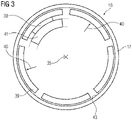
- Several extensions 41 running on the same radius can also be provided there, as is also the case, for example, in 3 is indicated by dashed lines.
- either one or more magnetic rail brake assemblies 14 can be located in this area. This can serve to increase the braking force and/or to provide redundancy for the magnetic rail brake arrangement 14 .
- the magnetic rail brake arrangements 14 are integrated into the superordinate control concept of the wind turbine 1 .
- the magnetic rail brake arrangements 14 or, if there are several contact shoes 39, at least some contact shoes 39 can thus fulfill holding functions and also carry out service braking or emergency braking, which lead to the generator 7 and thus ultimately the wind turbine 1 coming to a standstill.
- Air cooling 28 can now easily be implemented via the NDE side 42 of the rotor 15 .
- air is sucked in in the outer region of the rotor 15 and guided through the cooling channels 31 axially through the laminated core 18 and/or the air gap 25 to the side of the rotor 15 facing the functional component 9 .
- the heated air is then discharged axially out of the rotor 15 on the NDE side 42 via the magnetic rail brake arrangement 14 and the space between the spokes 38 .
- the air outlet is therefore radially further inwards than the air inlet.
- the air flow of the air cooling 28 is generated either by an external fan and/or by appropriate design of the spokes 37.
- the spokes 37 are designed in such a way that either a suction or pressure effect is generated when the rotor 15 rotates.
- the stator 22 of the generator 7 has a laminated core in which a winding system 30 is arranged, which forms end windings 23 on the end faces of the stator 22 .
- the stator 22 is sealed by a can 24 at least on the side of the air gap 25 . Liquid cooling of the stator 22, in particular oil cooling 27, is thus possible.
- the functional component has on the side facing the functional component 9 9 means for positioning and / or a can seal 26 on.
- Cooling channels 32 of the stator 22 and/or also distribution channels are provided in or on the laminated core of the stator 22 and/or the slots of the stator 22 in the region of a winding system and/or on the side of the generator flange extension 11 facing the stator 22 . These can also run inside the generator flange extension 11 .
- the magnetic rail brake arrangement 14 is integrated into the superordinate control concept of the wind turbine 1 .
- the brake assemblies 14 can thus perform holding functions and service braking, but also emergency braking. In the case of a plurality of magnetic track brake assemblies 14 acting independently of one another, this can serve to increase the braking force and/or to provide redundancy for the magnetic track brake assembly 14 .
- Additional sensors 44 in or on the magnetic rail brake assembly 14 are connected to the higher-level control device 29 and can monitor both the braking force and wear and the number of braking operations, etc.
- the electrical actuation energy of the magnetic rail brake arrangement 14 is provided, for example, by a battery 38 which is arranged in the gondola 8, in particular in the vicinity of the generator-gear unit 26.
- the described structure of the generator-gear unit according to the invention with the functional component 9 according to the invention ensures a compact design, particularly in the axial direction.
- the generator 7 is overhung, so that no end shield is to be provided on the NDE side 42.
- Only one cover 21 can be provided, which has corresponding air outlet and air inlet openings. This cover 21 is preferably made of GRP.
- the actuating energy of the respective magnetic track brake assemblies 14 is provided, for example, by a battery 38, which is advantageously arranged in the vicinity of the functional component 9, for example the generator flange extension 11 and/or the transmission flange extension 12.
- This magnetic rail brake arrangement 14 is controlled and activated or deactivated either by a superordinate control structure 29 or manually.
- the braking surface 43 is shown on the inside of the hollow cylinder 17.
- the braking surfaces 43 can also be designed as rails, which point radially inwards from the inside of the hollow cylinder 17 .
- Contact shoes 39 which in the illustrated case are still at a distance from the braking surface 43, press outwards in direction 40 when actuated and thus generate the desired braking effect of the rotor 15 and thus of the transmission 6 and ultimately of the wind turbine 1 through friction on the braking surface 43.
- Grinding shoes 39 and braking surfaces 43 or rails are complementary to one another in order to achieve the highest possible braking force.
- actuators 30 are provided on the extension(s) 41, for example, which, when actuated accordingly, bring about a radial movement of the grinding shoes 39 in direction 40 onto the braking surface 43.
- the magnetic rail brake arrangement 14 can have one or more contact shoes 39--in the present case five contact shoes 39--which can be controlled jointly or individually.
- the interior of the rotor can also be closed off comparatively easily by a cover 21 .
- stator 22 and the transmission 6 have oil cooling. Separate cooling circuits but also a common cooling circuit are conceivable.
- the rotor 15 of the generator 7 is cooled by air.
- laminated cores of the stator 22 and/or rotor 15 can be stacked axially throughout. However, laminated cores can be implemented both in the stator 22 and/or in the rotor 15, which are composed of a plurality of partial laminated cores that are spaced apart axially in order to create additional radial cooling gaps.
- a rotary dynamoelectric machine preferably an asynchronous machine or a synchronous machine, is provided as the generator 7 . Numbers of pole pairs from two to thirty are conceivable.
- Gear ratios between the wind rotor shaft 4 and the rotor 15 of the generator are aimed at, depending on the design, from 20 to 200.
- the transmission 6 and the generator 7 are arranged in particular axially separately from one another are. It is important that at least components of the magnetic rail brake arrangement 14 are arranged at least partially within the rotor 15 and/or the stator 22 when viewed axially.
- the braking torques achieved are greater the greater the distance between the hollow cylinder 17 and thus the braking surface 43 from the transmission output shaft 34 .
- a brake arrangement in particular a magnetic rail brake arrangement 14, axially within the generator 7--can also be implemented in particular with directly driven internal-rotor generators of a wind turbine 1.
Abstract
Die Erfindung betrifft eine Generator-Getriebe-Anordnung (26) einer Windkraftanlage (1) mit einem Funktionsbauteil (9)- wobei der Generator (7) einen Stator (22) und einen Rotor (15) aufweist,- wobei das Funktionsbauteil (9), an einer Stirnseite des Generators (7) angeordnet ist,- wobei das Funktionsbauteil (9), insbesondere der radial mittlere Abschnitt zumindest einen Fortsatz (41) aufweist, der zum Rotor (15) weist, insbesondere in den Innenraum des Rotors (15) weist,- wobei an dem Fortsatz (41) zumindest Komponenten zumindest einer Magnetschienen-Bremsanordnung (14) befestigt sind.The invention relates to a generator-gear assembly (26) of a wind turbine (1) with a functional component (9) - the generator (7) having a stator (22) and a rotor (15), - the functional component (9) , is arranged on an end face of the generator (7), - the functional component (9), in particular the radially central section, having at least one extension (41) which points towards the rotor (15), in particular into the interior of the rotor (15) has, - at least components of at least one magnetic rail brake arrangement (14) being fastened to the extension (41).
Description
Die Erfindung betrifft eine Generator-Getriebe-Anordnung und eine Windkraftanlage mit einer Generator-Getriebe-Anordnung.The invention relates to a generator-gear assembly and a wind turbine with a generator-gear assembly.
Viele Windkraftanlagen weisen einen Antriebsstrang mit Getriebe und Generator auf. Der Antriebsstrang weist dabei unter anderem ein mechanisches Bremssystem auf, das auf der dem Generator abgewandten Seite angeordnet ist, gemäß der
Derartige Anordnungen beanspruchen einen vergleichsweise großen axialen Bauraum.Such arrangements require a comparatively large amount of axial space.
Ausgehend davon liegt der Erfindung die Aufgabe zugrunde eine kompakte, leistungsfähige Generator-Getriebe-Anordnung, insbesondere einer Windkraftanlage zu schaffen. Dabei soll insbesondere die axiale Baulänge der Generator-Getriebe-Anordnung reduziert und kompaktiert werden. Der Antriebsstrang der Windkraftanlage soll außerdem einen vergleichsweise hohen Wirkungsgrad aufweisen.Proceeding from this, the object of the invention is to create a compact, powerful generator-gear assembly, in particular for a wind power plant. In particular, the axial overall length of the generator-gearbox arrangement should be reduced and compacted. The drive train of the wind turbine should also have a comparatively high level of efficiency.
Die Lösung der erfindungsgemäßen Aufgabe gelingt durch eine Generator-Getriebe-Anordnung einer Windkraftanlage mit einem Funktionsbauteil
- wobei der Generator einen Stator und einen Rotor aufweist,
- wobei das Funktionsbauteil, an einer Stirnseite des Generators angeordnet ist,
- wobei das Funktionsbauteil, insbesondere der radial mittlere Abschnitt zumindest einen Fortsatz aufweist, der zum Rotor weist, insbesondere in den Innenraum des Rotors weist,
- wobei an dem Fortsatz zumindest Komponenten zumindest einer Magnetschienen-Bremsanordnung befestigt sind.
- the generator having a stator and a rotor,
- wherein the functional component is arranged on a front side of the generator,
- wherein the functional component, in particular the radially central section, has at least one extension which points towards the rotor, in particular into the interior of the rotor,
- wherein at least components of at least one magnetic rail brake assembly are attached to the extension.
Die Lösung der erfindungsgemäßen Aufgabe gelingt auch durch eine Windkraftanlage mit einer erfindungsgemäßen Generator-Getriebe-Anordnung, wobei die Betätigung einer Magnetschienen-Bremsanordnung in eine Regelstruktur der Windkraftanlage eingebettet ist.The object according to the invention is also achieved by a wind turbine with a generator-gear assembly according to the invention, wherein actuation of a magnetic rail brake assembly is embedded in a control structure of the wind turbine.
Durch die erfindungsgemäße Anordnung der Magnetschienen-Bremsanordnung einer Generator-Getriebe-Einheit, insbesondere einer Windkraftanlage, zumindest abschnittsweise im Innenraum eines Rotors des Generators kann der Antriebsstrang der Windkraftanlage axial verkürzt ausgeführt werden. Damit kann eine Gondel der Windkraftanlage kürzer ausgeführt werden oder der nunmehr vergleichsweise gewonnene Bauraum anderweitig genutzt werden.The inventive arrangement of the magnetic rail brake assembly of a generator-gear unit, in particular a wind turbine, at least in sections in the interior of a rotor of the generator, the drive train of the wind turbine can be shortened axially. A nacelle of the wind turbine can thus be made shorter or the installation space that has now been gained in comparison can be used for other purposes.
Als Generator ist dabei eine rotatorische dynamoelektrische Maschine vorgesehen, vorzugsweise eine Asynchronmaschine oder Synchronmaschine. Als Getriebe sind dabei vorzugsweise zwei- oder dreistufige Planetenradgetriebe vorgesehen.A rotary dynamoelectric machine is provided as the generator, preferably an asynchronous machine or synchronous machine. Two or three-stage planetary gears are preferably provided as gears.
Das Funktionsbauteil ist stationär, bewegt sich also im Betrieb der Windkraftanlage nicht mit dem Rotor oder Komponenten des Getriebes mit.The functional component is stationary, i.e. it does not move with the rotor or components of the transmission during operation of the wind turbine.
Das Funktionsbauteil, insbesondere der radial äußere Bereich weist Fortsätze für das Getriebe und den Generator auf.The functional component, in particular the radially outer area, has extensions for the transmission and the generator.
Der radial mittlere Abschnitt des Funktionsbauteil weist einen oder mehrere Fortsätze auf, die zur Aufnahme bzw. zum Befestigen von zumindest Teilen einer Magnetschienen-Bremsanordnung geeignet sind.The radially middle section of the functional component has one or more extensions that are suitable for receiving or for fastening at least parts of a magnetic rail brake arrangement.
Der radial innere Bereich des Funktionsbauteils weist Aufnahmemöglichkeiten z.B. einen Stutzen als Sitz für ein Lager auf.The radially inner area of the functional component has accommodation options, e.g. a socket as a seat for a bearing.
Das Funktionsbauteil kann nur eine Abdeckung, ein Lagerschild mit und ohne Stutzen zur Aufnahme eines Lagers sein. Ebenso kann das Funktionsbauteil Lagerkomponenten und/oder Kühlkomponenten, als auch Flanschfortsätze von Getriebe und oder Generator am radial äußeren Bereich des Funktionsbauteils aufweisen.The functional component can only be a cover, an end shield with and without a socket for accommodating a bearing. The functional component can also be bearing components and/or cooling components, as well as flange extensions from the gearbox and/or generator have on the radially outer area of the functional component.
Das Funktionsbauteil weist somit einen Generatorflanschfortsatz und einen Getriebeflanschfortsatz auf. Diese Flanschfortsätze sind für die Aufnahme zumindest von Teilen des Generators bzw. von Teilen des Getriebes oder deren Gehäuse geeignet.The functional component thus has a generator flange extension and a transmission flange extension. These flange extensions are suitable for accommodating at least parts of the generator or parts of the transmission or their housing.
Der Generatorflanschfortsatz und der Getriebeflanschfortsatz sind in axial unterschiedliche Richtungen ausgerichtet.The generator flange extension and the transmission flange extension are aligned in axially different directions.
Vorzugsweise ist das Funktionsbauteil einstückig ausgeführt. Dadurch können geschraubte Übergangsstellen im Kraft- und Momentenfluss auch zwischen den einzelnen oben erwähnten Komponenten, unter anderem wie Generatorflanschfortsatz und Getriebeflanschfortsatz vermieden werden.The functional component is preferably designed in one piece. As a result, bolted transition points in the flow of forces and moments between the individual components mentioned above, such as the generator flange extension and the transmission flange extension, among other things, can be avoided.
Dazu ist das Funktionsbauteil als Gussteil ausgeführt oder aus Vollmaterial spanabhebend hergestellt.For this purpose, the functional component is designed as a cast part or is machined from solid material.
In einer weiteren Ausführungsform sind zumindest Teile bzw. Abschnitte des Funktionsbauteils bearbeitet, also gefräst, geschliffen etc. Ebenso ist es möglich, zumindest einige Komponenten, wie Generatorflanschfortsatz, Getriebeflanschfortsatz, Stutzen und/oder andere Fortsätze mittels Additive Manufactoring zumindest abschnittsweise stoffschlüssig zu ergänzen.In a further embodiment, at least parts or sections of the functional component are machined, i.e. milled, ground, etc. It is also possible to supplement at least some components, such as generator flange extension, transmission flange extension, socket and/or other extensions, at least in sections by means of additive manufacturing.
Dies gestattet auch die Schaffung zusätzlicher Formgebungen/ Rippen/Ausnehmungen, die einer Versteifung des Funktionsbauteils, Schaffung von Kühlkanälen oder Schmierkanälen innerhalb des Funktionsbauteils oder zumindest einer seiner Komponenten dienen.This also allows the creation of additional shapes/ribs/recesses that serve to stiffen the functional component, create cooling ducts or lubricating ducts within the functional component or at least one of its components.
Ebenso können die oben aufgeführten Komponenten des Funktionsbauteils, wie Fortsätze, Stutzen etc. auch angeschweißt oder z.B. mittels Schraubverbindung lösbar befestigt sein.Likewise, the components of the functional component listed above, such as extensions, sockets, etc., can also be welded on or fastened in a detachable manner, for example by means of a screw connection.
Eine erfindungsgemäße Magnetschienen-Bremsanordnung weist Schleifschuhe mit eingebauten Elektromagneten auf. Bei Stromfluss durch den Elektromagneten (Arbeitsstromprinzip) wird der Schleifschuh an den Rotor, insbesondere die Innenseite des Hohlzylinders gezogen bzw. gedrückt. Der axiale Abschnitt des Hohlzylinders weist Bremsflächen, insbesondere schienenartig ausgeformte Bremsflächen auf. Zwischen den sich bewegenden Bremsflächen und dem oder den darauf gepressten Schleifschuh bzw. den Schleifschuhen entsteht Reibung, die die kinetische Energie der Bewegung bzw. Rotation des Rotors in Wärme umwandelt bis die Bewegungsenergie des Antriebsstranges der Windkraftanlage "verbraucht" ist oder die Magnetschienen-Bremsanordnung deaktiviert wird.A magnetic rail brake arrangement according to the invention has slip shoes with built-in electromagnets. When current flows through the electromagnet (working current principle), the contact shoe is pulled or pressed against the rotor, in particular the inside of the hollow cylinder. The axial section of the hollow cylinder has braking surfaces, in particular braking surfaces shaped like rails. Friction occurs between the moving braking surfaces and the contact pad(s) pressed on it, which converts the kinetic energy of the movement or rotation of the rotor into heat until the kinetic energy of the drive train of the wind turbine is "consumed" or the magnetic rail brake arrangement is deactivated becomes.
Außerdem tritt eine zusätzliche Wirbelstrominduktion, insbesondere in einer schienenartig ausgeformten Bremsfläche auf, die eine entgegen der Rotation wirkende Kraft erzeugt.In addition, an additional eddy current induction occurs, in particular in a braking surface shaped like a rail, which generates a force acting against the rotation.
Da die Reibungskräfte mit sinkender Rotationsgeschwindigkeit zunehmen und die Wirbelstromkräfte abnehmen tritt eine nahezu lineare Bremswirkung der Magnetschienen-Bremsanordnung ein.Since the frictional forces increase with decreasing rotational speed and the eddy current forces decrease, an almost linear braking effect of the magnetic rail brake arrangement occurs.
Der Rotor weist eine Rotortragstruktur auf, an deren radialem Außenumfang ein Rotorblechpaket mit Permanentmagneten, einem Kurzschlusskäfigläufer oder einem Wicklungssystem angeordnet ist. Dieses Blechpaket ist mit einem Hohlzylinder fest verbunden, beispielsweise aufgeschrumpft. Der Hohlzylinder ist mit Verbindungelementen, insbesondere einer Speichenstruktur mit einer Rotornabe verbunden. Die Speichenstruktur überträgt Antriebs- aber auch Bremsmomente von und auf die Getriebeabtriebswelle. Durch die Speichenstruktur der Verbindungselemente wird das Gewicht der Rotortragestruktur reduziert. Der Hohlzylinder oder zumindest axiale Abschnitte des Hohlzylinders weisen außerdem an dessen Innenumfang Bremsflächen auf. Eine Bremswirkung durch die Magnetschienen-Bremsanordnung wird dabei erzielt, wenn die Schleifschuhe der Magnetschienen-Bremsanordnung gegen die Bremsfläche drücken.The rotor has a rotor support structure, on the radial outer circumference of which is arranged a laminated rotor core with permanent magnets, a squirrel-cage rotor or a winding system. This laminated core is firmly connected to a hollow cylinder, for example shrunk on. The hollow cylinder is connected to a rotor hub with connecting elements, in particular a spoke structure. The spoke structure transmits both drive and braking torques to and from the transmission output shaft. The spoke structure of the connecting elements reduces the weight of the rotor carrying structure. The hollow cylinder or at least axial sections of the hollow cylinder also have braking surfaces on its inner circumference. A braking effect by the magnetic rail brake arrangement is achieved when the contact shoes of the magnetic rail brake arrangement press against the braking surface.
Das Funktionsbauteil, insbesondere das Mittenteil, weist zumindest einen Fortsatz auf. Dieser Fortsatz, der in den Generatorraum ragt, ist umfänglich verlaufend ausgeführt oder als mehrere abschnittsweise umfänglich verlaufende Fortsätze ausgeführt, an denen zumindest Komponenten der Magnetschienen-Bremsanordnung angebracht sind.The functional component, in particular the central part, has at least one extension. This extension, which protrudes into the generator space, runs circumferentially or is designed as a plurality of extensions running circumferentially in sections, to which at least components of the magnetic rail brake arrangement are attached.
Im Generatorraum, im Bereich des Funktionsbauteils ist nunmehr eine Magnetschienen-Bremsenanordnung vorgesehen, die als Haltebremse oder Betriebsbremse der Windkraftanlage fungieren kann.In the generator room, in the area of the functional component, a magnetic rail brake arrangement is now provided, which can function as a holding brake or service brake of the wind turbine.
Bei der Magnetschienen-Bremsanordnung ist der Gegenpart der Schleifschuhe ein Teil der Rotortragestruktur, insbesondere ein dementsprechend bereitgestellter, ausgedrehter Hohlzylinder oder einer mit einer radial nach innen weisenden Schiene versehender Hohlzylinder. Der Hohlzylinder dient dabei gleichzeitig als Versteifungselement der Rotortragstruktur und damit des Rotors des Generators.In the case of the magnetic rail brake arrangement, the counterpart of the sliding shoes is a part of the rotor support structure, in particular a turned hollow cylinder provided accordingly or a hollow cylinder provided with a rail pointing radially inward. The hollow cylinder serves at the same time as a stiffening element for the rotor support structure and thus for the rotor of the generator.
Die elektrische Betätigungsenergie der Magnetschienen-Bremsanordnung, wird z.B. von einer Batterie bereitgestellt und dabei insbesondere über das Funktionsbauteil z.B. den Generatorflanschfortsatz und/oder den Getriebeflanschfortsatz geführt. Die Betätigung der Schleifschuhe der Magnetschienen-Bremsanordnung erfolgt beispielsweise entweder durch eine übergeordnete Regelstruktur der Windkraftanlage oder manuell. Dies beschreibt das Arbeitsstromprinzip.The electrical actuation energy of the magnetic rail brake arrangement is provided, for example, by a battery and is conducted in particular via the functional component, for example the generator flange extension and/or the transmission flange extension. The actuation of the contact shoes of the magnetic rail brake arrangement takes place, for example, either by a higher-level control structure of the wind turbine or manually. This describes the working current principle.
Bei dem Ruhestromprinzip, bei dem beispielsweise ein Elektromagnet gegen eine Feder arbeitet, um den Schleifschuh abzuheben, wird bei Ausfall der Hilfsenergie, z.B. durch einen Drahtbruch, eine Bremsung eingeleitet. Dies ist als "failsafe" für sicherheitsbedingte Notbremsungen wichtig.With the closed-circuit principle, in which, for example, an electromagnet works against a spring to lift the contact pad, braking is initiated if the auxiliary power fails, e.g. due to a wire break. This is important as a "failsafe" for safety-related emergency braking.
Die Magnetschienen-Bremsenanordnung weist nicht nur einen Schleifschuh auf, sondern es sind an dem oder den Fortsätzen des radial mittleren Teils mehrere Schleifschuhe angeordnet, die zusammen oder alternierend betätigbar sind. Die Schleifschuhe und deren komplementären Bremsflächen können innerhalb der Innenfläche des Hohlzylinders axial versetzt angeordnet sein. Dies kann die Torsionswirkung aufgrund der Bremsung reduzieren und den Bremsabrieb auf mehrere Bremsanordnungen verteilen.The magnetic track brake arrangement has not only one contact shoe, but several contact shoes are arranged on the extension(s) of the radially central part. which can be operated together or alternately. The grinding shoes and their complementary braking surfaces can be arranged axially offset within the inner surface of the hollow cylinder. This can reduce the torsional effect due to braking and distribute brake wear across multiple brake assemblies.
Dadurch, dass die Rotortragstruktur speichenförmig ausgeführt ist, sind Wartungsarbeiten, z.B. Tausch von Bremsenkomponenten, einfach durchführbar. Dies gelingt z.B. im Stillstand der Anlage durch einen axialen Durchgriff zwischen den Speichen der Rotortragestruktur.Because the rotor support structure is spoke-shaped, maintenance work, e.g. replacing brake components, can be carried out easily. This can be achieved, for example, when the system is at a standstill by means of an axial reach through between the spokes of the rotor support structure.
Durch die erfindungsgemäße Anordnung der Magnetschienen-Bremsanordnung an den Funktionsbauteilen und der damit erfindungsgemäßen kompakten Generator-Getriebe-Einheit ergibt sich eine Reduzierung der axialen Baulänge.The arrangement according to the invention of the magnetic rail brake arrangement on the functional components and the compact generator-gear unit according to the invention result in a reduction in the overall axial length.
Aufgrund der fliegenden Lagerung des Generators, kann auf ein NDE-seitiges Lagerschild verzichtet werden.Due to the cantilever mounting of the generator, there is no need for an end shield on the NDE side.
Es ist somit auch keine Abdeckung der rotierenden Magnetschienen-Bremsenanordnung notwendig, da diese innerhalb des, nicht ohne weiteres, zugänglichen Innenraumes des Rotors angeordnet ist.It is therefore also not necessary to cover the rotating magnetic track brake arrangement, since this is arranged inside the interior of the rotor, which is not readily accessible.
Aufgrund der Bremsanordnung an dem Funktionsbauteil ist ein kurzer, direkter Kraft-/Momentenfluss von der Bremsanordnung, insbesondere Schleifschuh und Bremsfläche, über den Rotor zum Getriebe gewährleistet. Dies kann insbesondere durch die Einstückigkeit des Funktionsbauteils unterstützt werden, indem keine geschraubten Übergangsstellen im Kraft- bzw. Momentenfluss vorhanden sind. Damit können auch die Notwendigkeiten von reibschlüssigen Verbindungen entfallen oder zumindest minimiert werden.Because of the braking arrangement on the functional component, a short, direct flow of force/torque from the braking arrangement, in particular the contact shoe and braking surface, via the rotor to the transmission is ensured. This can be supported in particular by the one-piece nature of the functional component, in that there are no screwed transition points in the flow of forces or moments. This also eliminates the need for frictional connections or at least minimizes them.
Die Generator-Getriebe-Anordnung einer Windkraftanlage mit einem gemeinsamen Funktionsbauteil dieser Generator-Getriebe-Einheit ist nunmehr, insbesondere axial, äußerst kompakt ausgeführt.The generator-gear arrangement of a wind turbine with a common functional component of this generator-gear unit is now extremely compact, especially axially.
Die Kühlung zumindest dieses Generators kann durch Luft oder eine Kühlflüssigkeit erfolgen. In einer Ausführungsform ist ein Stator des Generators mit einer Ölkühlung versehen, während der Rotor eine Luftkühlung aufweist. Der Stator ist dabei durch ein Spaltrohr im Luftspalt der dynamoelektrischen Maschine vom Rotor abgeschottet. Mittels Ausnehmungen bzw. Kanälen im Blechpaket des Stators und/oder im Generatorflanschfortsatz ist eine Ölkühlung realisiert.At least this generator can be cooled by air or a cooling liquid. In one embodiment, a stator of the generator is oil-cooled, while the rotor is air-cooled. The stator is separated from the rotor by a can in the air gap of the dynamoelectric machine. Oil cooling is realized by means of recesses or channels in the laminated core of the stator and/or in the generator flange extension.
Das Funktionsbauteil weist in diesem Fall also Ausnehmungen bzw. Kanäle und Mittel zur Abdichtung des Spaltrohrs auf, z.B. Komponenten einer Labyrinthdichtung.In this case, the functional component has recesses or channels and means for sealing the can, e.g. components of a labyrinth seal.
Das Getriebe ist insbesondere ein zwei- oder dreistufiges Planetenradgetriebe, das sich auf der der Generatorseite abgewandten Seite des Funktionsbauteils erstreckt. Auch dort kann eine Ölkühlung vorgesehen sein, zu dem im Getriebeflanschfortsatz Ausnehmungen bzw. Kanäle vorgesehen sind.The gear is in particular a two- or three-stage planetary gear which extends on the side of the functional component facing away from the generator side. Oil cooling can also be provided there, for which recesses or channels are provided in the transmission flange extension.
Das radial betrachtet mittlere Teil des Funktionsbauteils verbindet den Generatorflanschfortsatz und den Getriebeflanschfortsatz. Des Weiteren stellt dieses mittlere Teil eine mechanische Verbindung zu einem Stutzen her, der als Lagersitz geeignet ist, um eine Getriebeabtriebswelle, die mit dem Rotor drehfest und drehmomentenübertragend verbunden ist, zu lagern.The middle part of the functional component viewed radially connects the generator flange extension and the transmission flange extension. Furthermore, this middle part creates a mechanical connection to a socket, which is suitable as a bearing seat to mount a transmission output shaft, which is connected to the rotor in a rotationally fixed and torque-transmitting manner.
Als Lager sind dabei beispielsweise ein doppelreihiges Lager in X-Anordnung oder Kegelrollenlager etc. vorgesehen.A double-row bearing in an X arrangement or tapered roller bearings etc. are provided as bearings.
Um eine Schmierung der Lageranordnung zu gewährleisten, sind im Funktionsbauteil, insbesondere im mittleren Teil und/oder im Stutzen, Schmierkanäle vorgesehen.In order to ensure lubrication of the bearing arrangement, lubricating channels are provided in the functional component, in particular in the central part and/or in the socket.
Die Getriebeabtriebswelle ist mechanisch beispielsweise über eine lösbare Spannvorrichtung oder eine elektrisch isolierende Flanschverbindung mit einer Rotornabe der Rotortragstruktur drehmomentenübertragend verbunden.The transmission output shaft is mechanically connected in a torque-transmitting manner to a rotor hub of the rotor support structure, for example via a detachable clamping device or an electrically insulating flange connection.
Durch diesen einfachen kompakten Aufbau ergibt sich auch eine einfache Montage bzw. eine einfache Schnittstelle für ein Turner-Getriebe, das für eine Rotorblattmontage der Windkraftanlage erforderlich ist.This simple, compact construction also results in simple assembly or a simple interface for a Turner gear, which is required for assembling the rotor blades of the wind turbine.
Durch die Mehrfachnutzung von Bauteilen, (z.B. Bremsfläche bzw. Bremsschiene als Versteifungselement, Funktionsbauteil unter anderem als gemeinsames Gussgehäuse mit Flansch für Generator und Getriebe, der als Kraftschluss für Bremskräfte und Momente dient etc.) wird eine kompakte Generator-Getriebe-Einheit einer Windkraftanlage geschaffen.The multiple use of components (e.g. brake surface or brake rail as a stiffening element, functional component as a common cast housing with flange for generator and gearbox, which serves as a frictional connection for braking forces and moments, etc.) creates a compact generator-gear unit of a wind turbine .
Eine Windkraftanlage mit einer derartigen erfindungsgemäßen Generator-Getriebe-Einheit, führt aufgrund der Mehrfachnutzung der Bauteile bzw. Komponenten zu einer äußerst kompakten und leistungsfähigen Windkraftanlage.A wind power plant with such a generator-gear unit according to the invention leads to an extremely compact and powerful wind power plant due to the multiple use of the parts or components.
Durch eine Ölkühlung von Generator und/oder Getriebe und einer Luftkühlung, zumindest des Rotors, wird eine Windkraftanlage mit vergleichsweise hohem Wirkungsgrad bereitgestellt.A wind power plant with a comparatively high degree of efficiency is provided by oil cooling of the generator and/or transmission and air cooling, at least of the rotor.
Die Erfindung sowie weitere Ausgestaltungen der Erfindung werden in den folgenden Ausführungsbeispielen prinzipiell dargestellt; darin zeigen:
- FIG 1
- eine prinzipiell dargestellte Windkraftanlage,
- FIG 2
- ein Funktionsteil, mit einem Generator,
- FIG 3
- ein prinzipieller Querschnitt der Magnetschienen-Bremsanordnung.
- FIG 1
- a wind turbine shown in principle,
- FIG 2
- a functional part, with a generator,
- 3
- a basic cross-section of the magnetic rail brake assembly.
Es sei angemerkt, dass sich Begriffe wie "axial", "radial", "tangential" etc. auf die in der jeweiligen Figur bzw. im jeweils beschriebenen Beispiel zum Einsatz kommende Achse beziehen. Mit anderen Worten beziehen sich die Richtungen axial, radial, tangential stets auf eine Drehachse des Rotors und damit auf die entsprechende Symmetrieachse des Stators. Dabei beschreibt "axial" eine Richtung parallel zur Achse, "radial" beschreibt eine Richtung orthogonal zur Achse, auf diese zu oder auch von ihr weg, und "tangential" ist eine Richtung, die in konstantem radialen Abstand zur Achse 35 und bei konstanter Axialposition kreisförmig um die Achse 35 herum gerichtet ist. Der Ausdruck "in Umfangsrichtung" ist mit "tangential" gleichzusetzen.It should be noted that terms such as "axial", "radial", "tangential" etc. refer to the axis used in the respective figure or in the example described in each case. In other words, the directions axial, radial, tangential always relate to an axis of rotation of the rotor and thus to the corresponding axis of symmetry of the stator. "Axial" describes a direction parallel to the axis, "radial" describes a direction orthogonal to the axis, towards or away from it, and "tangential" is a direction at a constant radial distance from the
In Bezug auf eine Fläche, beispielsweise eine Querschnittsfläche, beschreiben die Begriffe "axial", "radial", "tangential" etc. die Orientierung des Normalenvektors der Fläche, d.h. desjenigen Vektors, der senkrecht auf der betroffenen Fläche steht.In relation to a surface, for example a cross-sectional surface, the terms "axial", "radial", "tangential", etc. describe the orientation of the normal vector of the surface, i.e. the vector which is perpendicular to the surface concerned.
Der Begriff "benachbart" soll im Zusammenhang mit Bauteilen, beispielsweise mit Spulen oder Statorzähnen, ausdrücken, dass sich im Falle von "benachbarten Bauteilen" zwischen diesen beiden Bauteilen insbesondere kein weiteres derartiges Bauteil befindet, sondern höchstens ein leerer Zwischenraum oder gegebenenfalls ein andersartiges Bauteil.The term "adjacent" in connection with components, for example with coils or stator teeth, is intended to express that in the case of "adjacent components" there is in particular no other such component between these two components, but at most an empty space or possibly a different type of component.
Unter dem Ausdruck "koaxiale Bauteile", beispielsweise koaxiale Komponenten wie Rotor und Stator, werden hier Bauteile verstanden, die gleiche Normalenvektoren aufweisen, für die also die von den koaxialen Bauteilen definierten Ebenen parallel zueinander sind. Des Weiteren soll der Ausdruck beinhalten, dass die Mittelpunkte koaxialer Bauteile auf der gleichen Rotations- bzw. Symmetrieachse liegen. Diese Mittelpunkte können jedoch auf dieser Achse gegebenenfalls an verschiedenen axialen Positionen liegen und die genannten Ebenen also einen Abstand >0 voneinander haben. Der Ausdruck verlangt nicht zwangsläufig, dass koaxiale Bauteile den gleichen Radius haben.The expression "coaxial components", for example coaxial components such as rotor and stator, is understood here to mean components which have the same normal vectors, ie for which the planes defined by the coaxial components are parallel to one another. Furthermore, the expression should include that the center points of coaxial components lie on the same axis of rotation or symmetry. These centers can, however, possibly lie at different axial positions on this axis and the said planes can therefore have a distance >0 from one another. The expression does not necessarily require that coaxial components have the same radius.
Der Begriff "komplementär" meint im Zusammenhang mit zwei Komponenten, welche "komplementär" zueinander sind, dass ihre äußeren Formen derart ausgestaltet sind, dass die eine Komponente vorzugsweise vollständig in der zu ihr komplementären Komponente angeordnet werden kann, so dass sich die innere Oberfläche der einen Komponente und die äußere Oberfläche der anderen Komponente idealerweise lückenlos bzw. vollflächig berühren. Konsequenterweise ist also im Falle von zwei zueinander komplementären Gegenständen die äußere Form des einen Gegenstandes durch die äußere Form des anderen Gegenstandes festgelegt.The term "complementary" means in connection with two components, which are "complementary" to each other, that their outer shapes are designed such that one component can preferably be arranged completely in the component complementary to it, so that the inner surface of the touch one component and the outer surface of the other component ideally without gaps or over the entire surface. Consequently, in the case of two mutually complementary objects, the external shape of one object is determined by the external shape of the other object.
Der Übersichtlichkeit wegen werden in den Figuren teilweise in den Fällen, in denen Bauteile mehrfach vorhanden sind, häufig nicht sämtliche dargestellten Bauteile mit Bezugszeichen versehen.For the sake of clarity, in some cases in the figures in which components are present more than once, not all of the components shown are provided with reference symbols.
Die
Der Generator 7 und das Getriebe 6 sind in einer Gondel 8 der Windkraftanlage 1 angeordnet. In der Gondel 8 sind unter anderem auch Umrichter des Generators 7, Überwachungs- und Regelsysteme der Windkraftanlage 1 angeordnet. Des Weiteren sind in der Gondel 8 zumindest Komponenten, z.B. Wärmetauscher unterschiedlichster Kühlsysteme der Windkraftanlagenkomponenten, wie Generator 7, Getriebe 6 etc. vorgesehen.The
Des Weiteren sind in der Gondel 8 nicht näher dargestellte Drehmomentstützen der Generator-Getriebe-Anordnung 26 vorhanden, die Antriebs- und Bremsmomente aufnehmen.Furthermore, in the
Getriebe 6 und Generator 7 können auch durch einen Wellenabschnitt voneinander getrennt sein. Dabei erhält dann der Generator 7 ein Funktionsbauteil 9 und das Getriebe 6 lediglich einen stirnseitigen Abschluss. Um dennoch eine axiale Kompaktheit zu erreichen ist u.a. entscheidend, dass eine Magnetschienen-Bremsanordnung 14 zumindest zum Teil radial innerhalb des Generators 7 bzw. innerhalb eines Rotors 15 des Generators 7 angeordnet ist. Dies wird ermöglicht, indem ein Funktionsbauteil 9 einen oder mehrere axial erstreckende Fortsätze 41 Richtung Rotor 15 aufweist, auf die später näher eingegangen wird.
Der Getriebeflanschfortsatz 12 nimmt zumindest Komponenten eines Getriebes 6, insbesondere eines zwei- oder dreistufigen Planetenradgetriebes auf, wie z.B. ein ortsfestes Hohlrad.The
Aus dem Getriebe 6 ragt axial eine Getriebeabtriebswelle 34. Diese rotiert um eine Achse 35, die entweder in axialer Flucht der Windrotorachse 5 verläuft oder zu dieser achsparallel ausgerichtet ist, also koaxial angeordnet ist.A
Die Getriebeabtriebswelle 34 - hier hohl ausgeführt - ist mit dem Rotor 15 des Generators 7 über eine Rotornabe 36 drehfest und drehmomentenübertragend verbunden.The transmission output shaft 34 - designed hollow here - is rotatably connected to the
Die Getriebeabtriebswelle 34 ist in einer Lageranordnung 13 gelagert, die in einem Stutzen 33 des Funktionsbauteils 9 positioniert ist. Nicht näher dargestellte Schmiermittelkanäle für die Lageranordnung 13 können dabei innerhalb des Stutzens 33 und/oder des Funktionsbauteils 9 vorgesehen sein.The
Das Drehmoment im Energieerzeugungsmodus, aber auch ein Bremsmoment wird über die Welle-Nabe-Verbindung zwischen der Getriebeabtriebswelle 34 und der Rotornabe 36 übertragen.Torque in the power generation mode, but also braking torque, is transmitted via the shaft-hub connection between the
Die Welle-Nabe-Verbindung kann dabei grundsätzlich als form- oder kraftschlüssige Verbindungen ausgeführt sein. Aufgrund der anstehenden Beanspruchungen, wie große und/oder wechselseitige Beanspruchungen, werden vorzugsweise Spannsätze oder Pressverbände eingesetzt.The shaft-hub connection can basically be designed as a positive or non-positive connection. Because of the stresses that are to be expected, such as large and/or alternating stresses, clamping sets or interference fits are preferably used.
Der Rotor 15 weist eine Rotortragstruktur 16 auf, die die Rotornabe 36, einen Hohlzylinder 17 und Versteifungselemente bzw. Verbindungselemente, wie z.B. Speichen 37 beinhaltet. Der zumindest eine Bremsfläche 43 aufweisende Hohlzylinder 17 wirkt zusätzlich versteifend auf die Rotortragstruktur 16.The
Die Bremsfläche 43 des Hohlzylinders 17 kann als Fläche innerhalb des Hohlzylinders 17 ausgewiesen sein. Ebenso ist es möglich, dass auf der Innenseite des Hohlzylinders 17 eine radial nach innen weisende Schienenanordnung als Bremsfläche 43 vorgesehen ist.The
Das Funktionsbauteil 9 auf der dem Getriebe 6 zugewandten Seite, kann auch als Lagerschild des Generators 7 ausgebildet sein.The
Zumindest einige Komponenten der Magnetschienen-Bremsanordnung 14 sind im Innenraum des Rotors 15 angeordnet, wenn auch nicht unbedingt radial innerhalb des Blechpakets 18 des Rotors 15.At least some components of the magnetic
Die Magnetschienen-Bremsanordnung 14 ist vorzugsweise auf einer Seite des Rotors 15, insbesondere der dem Funktionsbauteil 9 zugewandten Seite angeordnet. Dabei ist in dieser Darstellung die Bremsfläche 43 vor allem in einer axialen Verlängerung des Hohlzylinders 17 Richtung Funktionsbauteil 9, axial betrachtet außerhalb des Blechpakets 18 des Rotors 15 ausgebildet.The magnetic
Eine mehr axial mittige Anordnung der Bremsfläche 43 innerhalb des Hohlzylinders 17, also radial "unterhalb" des Blechpakets 18 des Rotors 15 kann die Torsionswirkung auf die Rotortragstruktur 16 während des Bremsens reduzieren.A more axially central arrangement of the
Vorzugsweise ist die Rotortragstruktur 16, räumlich betrachtet, schalenförmig ausgeführt, um einem Stutzen 33, einer Lageranordnung 13 und/oder einer Bremsenanordnung 14 Bauraum zu bieten. Die Öffnung der "Schale" weist dabei zum Funktionsbauteil 9.The
Umfänglich auf der Rotortragstruktur 16 angeordnet ist das Blechpaket 18 des Rotors 15, das durch Druckscheiben 19 paketiert ist. Das Rotorblechpaket 18 weist Permanentmagnete 20 auf, die sich in im Wesentlichen axial verlaufenden Ausnehmungen befinden. Diese Permanentmagnete 20 können auch an der Oberfläche des Blechpakets 18 angeordnet sein.The
Ebenso können die Permanentmagnete 20 unter Berücksichtigung einer effizienten Magnetflussführung auch V-förmig im Blechpaket 18 angeordnet sein.Likewise, the
Der dem Funktionsbauteil 9 zugewandte Teil des Hohlzylinders 17 ist in dieser Ausführung zumindest abschnittsweise als Bremsfläche 43 ausgeführt.The part of the
Die Schleifschuhe 39 sind an einem Fortsatz 41 des Funktionsbauteils 9 positioniert. Der Fortsatz 41 ist vorzugsweise als Ring, je nach Ausführung der Rotortragestruktur 16 am radial mittleren Teil des Funktionsbauteil 9 vorgesehen. Es können dort auch mehrere auf gleichem Radius verlaufende Fortsätze 41 vorgesehen sein, wie dies beispielsweise auch in
Die Magnetschienen-Bremsanordnungen 14 sind in das übergeordnete Regelkonzept der Windkraftanlage 1 eingebunden. Damit können die Magnetschienen-Bremsanordnungen 14 oder falls mehrere Schleifschuhe 39 vorhanden sind, zumindest einige Schleifschuhe 39 Haltefunktionen erfüllen, als auch Betriebsbremsungen oder Notfallbremsungen durchführen, die zum Stillstand des Generators 7 und damit letztlich der Windkraftanlage 1 führen.The magnetic
Über die NDE-Seite 42 des Rotors 15 kann nunmehr einfach eine Luftkühlung 28 realisiert werden. Dabei wird beispielsweise Luft im äußeren Bereich des Rotors 15 angesaugt und durch die Kühlkanäle 31 axial durch das Blechpaket 18 und/oder den Luftspalt 25 auf die dem Funktionsbauteil 9 zugewandten Seite des Rotors 15 geführt. Über die Magnetschienen-Bremsanordnung 14 und den Speichenzwischenraum 38 wird die erwärmte Luft dann axial wieder aus dem Rotor 15 auf der NDE-Seite 42 abgegeben. Der Luftaustritt ist also radial weiter innen als der Lufteinlass.Air cooling 28 can now easily be implemented via the
Der Luftstrom könnte aber auch umgedreht werden. Dies hätte jedoch den Nachteil, dass der Bremsabrieb der Magnetschienen-Bremsenanordnung 14 in den Bereich des Luftspalts 25 gelangt.The air flow could also be reversed. However, this would have the disadvantage that the brake dust from the magnetic
Der Luftstrom der Luftkühlung 28 wird entweder durch einen Fremdlüfter und/oder durch entsprechende Gestaltung der Speichen 37 generiert. Die Speichen 37 sind, um eine Luftkühlung 28 des Rotors 15 zu realisieren, derart gestaltet, dass entweder eine Sog- oder Druckwirkung bei Drehung des Rotors 15 generiert wird.The air flow of the air cooling 28 is generated either by an external fan and/or by appropriate design of the
Der Stator 22 des Generators 7 weist ein Blechpaket auf, in dem ein Wicklungssystem 30 angeordnet ist, das an den Stirnseiten des Stators 22 Wickelköpfe 23 ausbildet. Der Stator 22 ist zumindest auf der Seite des Luftspaltes 25 durch ein Spaltrohr 24 abgedichtet. Damit ist eine Flüssigkeitskühlung des Stators 22, insbesondere eine Ölkühlung 27 möglich. Auf der dem Funktionsbauteil 9 zugewandten Seite weist das Funktionsbauteil 9 Mittel zur Positionierung und/oder einer Spaltrohrdichtung 26 auf. Im bzw. am Blechpaket des Stators 22 und/oder den Nuten des Stators 22 im Bereich eines Wicklungssystems und/oder an der dem Stator 22 zugewandten Seite des Generatorflanschfortsatzes 11 sind Kühlkanäle 32 des Stators 22 und/oder auch Verteilungskanäle vorgesehen. Diese können auch innerhalb des Generatorflanschfortsatzes 11 verlaufen.The
Die Magnetschienen-Bremsanordnung 14 ist in das übergeordnete Regelkonzept der Windkraftanlage 1 eingebunden. Damit können die Bremsanordnungen 14 Haltefunktionen und Betriebsbremsungen, aber auch Notfallbremsungen durchführen. Bei mehreren unabhängig voneinander agierenden Magnetschienen-Bremsanordnungen 14 kann dies der Bremskraftsteigerung und/oder der Redundanz der Magnetschienen-Bremsanordnung 14 dienen.The magnetic
Zusätzliche Sensoren 44 in bzw. an der Magnetschienen-Bremsanordnung 14, sind mit der übergeordneten Regeleinrichtung 29 verbunden und können sowohl die Bremskraft, als auch Abnutzung, und die Anzahl der Bremsvorgänge etc. überwachen.
Die elektrische Betätigungsenergie der Magnetschienen-Bremsanordnung 14, wird z.B. von einer Batterie 38 bereitgestellt, die in der Gondel 8, insbesondere in der Nähe der Generator-Getriebe-Einheit 26 angeordnet ist.The electrical actuation energy of the magnetic
Grundsätzlich ist durch den beschriebenen Aufbau der erfindungsgemäßen Generator-Getriebe-Einheit mit dem erfindungsgemäßen Funktionsbauteils 9 eine kompakte Ausführung gewährleistet, insbesondere in axialer Richtung. Der Generator 7 ist fliegend gelagert, so dass auf der NDE-Seite 42 kein Lagerschild vorzusehen ist. Es kann lediglich eine Abdeckung 21 vorgesehen werden, die dementsprechende Luft-Aus- und Luft-Einlassöffnungen aufweist. Diese Abdeckung 21 ist vorzugsweise aus GFK.In principle, the described structure of the generator-gear unit according to the invention with the
Die Betätigungsenergie der jeweiligen Magnetschienen-Bremsanordnungen 14 wird z.B. von einer Batterie 38 bereitgestellt, die vorteilhafterweise in der Nähe des Funktionsbauteils 9, z.B. den Generatorflanschfortsatz 11 und/oder den Getriebeflanschfortsatz 12 angeordnet ist. Diese Magnetschienen-Bremsanordnung 14 wird entweder durch eine übergeordnete Regelstruktur 29 oder manuell angesteuert und aktiviert bzw. deaktiviert.The actuating energy of the respective magnetic
Schleifschuhe 39 und Bremsflächen 43 bzw. Schienen sind komplementär zueinander, um eine möglichst hohe Bremskraft zu erzielen.Grinding
An dem oder den Fortsätzen 41 sind dazu beispielsweise Aktoren 30 vorgesehen, die bei dementsprechender Ansteuerung eine radiale Bewegung der Schleifschuhe 39 in Richtung 40 auf die Bremsfläche 43 bewirken.For this purpose, actuators 30 are provided on the extension(s) 41, for example, which, when actuated accordingly, bring about a radial movement of the grinding
Die Magnetschienen-Bremsanordnung 14 kann dabei einen oder mehrere Schleifschuhe 39 - im vorliegende Fall fünf Schleifschuhe 39 - aufweisen, die gemeinsam oder einzeln ansteuerbar sind.The magnetic
Diese zum Teil rotierende Komponenten der Magnetschienen-Bremsanordnung 14 müssen aufgrund ihres schwer zugänglichen Einbauortes nicht zusätzlich abgedeckt werden. Jedoch kann eine Abdeckung sinnvoll sein, um den Schmutzpartikel vom Innenraum des Rotors 15 fernzuhalten.These partly rotating components of the magnetic
Der Rotorinnenraum lässt sich auch vergleichsweise einfach durch eine Abdeckung 21 abschotten.The interior of the rotor can also be closed off comparatively easily by a
In einer Ausführung weist der Stator 22 und das Getriebe 6 eine Ölkühlung auf. Dabei sind getrennte Kühlkreisläufe aber auch ein gemeinsamer Kühlkreislauf denkbar. Der Rotor 15 des Generators 7 wird dabei mittels Luft gekühlt.In one embodiment, the
Dabei können die Blechpakete von Stator 22 und/oder Rotor 15 axial durchgängig gestapelt sein. Es sind aber sowohl beim Stator 22 und/oder auch beim Rotor 15 Blechpakete umsetzbar, die sich axial aus mehreren voneinander beabstandeten Teilblechpaketen zusammensetzen, um zusätzliche radiale Kühlspalte zu schaffen.The laminated cores of the
Als Generator 7 ist dabei eine rotatorische dynamoelektrische Maschine vorgesehen, vorzugsweise eine Asynchronmaschine oder Synchronmaschine. Dabei sind Polpaarzahlen von zwei bis dreißig vorstellbar.A rotary dynamoelectric machine, preferably an asynchronous machine or a synchronous machine, is provided as the
Dabei werden Übersetzungsverhältnisse zwischen Windrotorwelle 4 und Rotor 15 des Generators je nach Ausführung von 20 bis 200 angestrebt.Gear ratios between the wind rotor shaft 4 and the
Um einen kompakten Antriebsstrang, also Generator-Getriebe-Anordnung 26 der Windkraftanlage 1 zu erhalten, können die bisher beschriebenen und gezeigten Merkmale der Erfindung auch in anderen beliebigen Kombinationen zusammengeführt werden. Beispielsweise müssen Getriebe 6 und Generator 7 nicht zwangsläufig über das beschriebene Funktionsbauteil 9 mechanisch zusammenhängen bzw. zusammenwirken, wie in
Vielmehr ist alternativ auch denkbar, dass das Getriebe 6 und der Generator 7 insbesondere axial voneinander getrennt angeordnet sind. Wichtig ist, dass zumindest Komponenten der Magnetschienen-Bremsanordnung 14 axial betrachtet zumindest teilweise innerhalb des Rotors 15 und/oder des Stators 22 angeordnet sind.Rather, it is alternatively also conceivable that the
Die erzielten Bremsmomente sind umso größer je größer der Abstand des Hohlzylinders 17 und damit der Bremsfläche 43 von der Getriebeabtriebswelle 34 ist.The braking torques achieved are greater the greater the distance between the
Die Grundidee - eine Bremsenanordnung, insbesondere Magnetschienen-Bremsanordnung 14 axial innerhalb des Generators 7 anzuordnen - lässt sich insbesondere auch bei direktangetriebenen Innenläufergeneratoren einer Windkraftanlage 1 realisieren.The basic idea--arranging a brake arrangement, in particular a magnetic
Claims (15)
Priority Applications (5)
| Application Number | Priority Date | Filing Date | Title |
|---|---|---|---|
| EP20211250.4A EP4008898A1 (en) | 2020-12-02 | 2020-12-02 | Generator-gearbox-arrangement of a wind turbine with brake |
| US18/036,317 US11891981B2 (en) | 2020-12-02 | 2021-11-26 | Generator/gearbox arrangement for a wind power installation with a brake |
| EP21820539.1A EP4256199A1 (en) | 2020-12-02 | 2021-11-26 | Generator/gearbox arrangement for a wind power installation with a brake |
| PCT/EP2021/083149 WO2022117452A1 (en) | 2020-12-02 | 2021-11-26 | Generator/gearbox arrangement for a wind power installation with a brake |
| CN202180081334.4A CN116648557A (en) | 2020-12-02 | 2021-11-26 | Generator/gearbox arrangement for a wind power plant with a brake |
Applications Claiming Priority (1)
| Application Number | Priority Date | Filing Date | Title |
|---|---|---|---|
| EP20211250.4A EP4008898A1 (en) | 2020-12-02 | 2020-12-02 | Generator-gearbox-arrangement of a wind turbine with brake |
Publications (1)
| Publication Number | Publication Date |
|---|---|
| EP4008898A1 true EP4008898A1 (en) | 2022-06-08 |
Family
ID=73694849
Family Applications (2)
| Application Number | Title | Priority Date | Filing Date |
|---|---|---|---|
| EP20211250.4A Withdrawn EP4008898A1 (en) | 2020-12-02 | 2020-12-02 | Generator-gearbox-arrangement of a wind turbine with brake |
| EP21820539.1A Pending EP4256199A1 (en) | 2020-12-02 | 2021-11-26 | Generator/gearbox arrangement for a wind power installation with a brake |
Family Applications After (1)
| Application Number | Title | Priority Date | Filing Date |
|---|---|---|---|
| EP21820539.1A Pending EP4256199A1 (en) | 2020-12-02 | 2021-11-26 | Generator/gearbox arrangement for a wind power installation with a brake |
Country Status (4)
| Country | Link |
|---|---|
| US (1) | US11891981B2 (en) |
| EP (2) | EP4008898A1 (en) |
| CN (1) | CN116648557A (en) |
| WO (1) | WO2022117452A1 (en) |
Citations (3)
| Publication number | Priority date | Publication date | Assignee | Title |
|---|---|---|---|---|
| US8376708B2 (en) | 2009-06-30 | 2013-02-19 | General Electric Company | Drivetrain system for a wind turbine generator and method of assembling the same |
| FR3016252A1 (en) * | 2014-01-07 | 2015-07-10 | Dcns | DEVICE FOR TRANSFORMING MECHANICAL ENERGY INTO ELECTRIC ENERGY, IN PARTICULAR FOR A WINDMILL |
| DE102018100951A1 (en) * | 2018-01-17 | 2019-07-18 | Wobben Properties Gmbh | Locking and braking module for a wind turbine as well as generator and wind turbine with selbigem |
Family Cites Families (7)
| Publication number | Priority date | Publication date | Assignee | Title |
|---|---|---|---|---|
| US519674A (en) * | 1894-05-08 | heilmann | ||
| US895618A (en) * | 1906-11-20 | 1908-08-11 | Leonard K Clark | Power-transmitting device. |
| US3723795A (en) * | 1971-07-12 | 1973-03-27 | M Baermann | Eddy-current and hysteresis brake for track-bound vehicles |
| US4738148A (en) * | 1984-12-12 | 1988-04-19 | Peter Norton | Starter drive |
| US7948100B2 (en) * | 2007-12-19 | 2011-05-24 | General Electric Company | Braking and positioning system for a wind turbine rotor |
| US20140110947A1 (en) * | 2012-10-24 | 2014-04-24 | Vestas Wind Systems A/S | Wind turbine generator having an eddy current brake, wind turbine having such a generator, and associated methods |
| US10054204B2 (en) * | 2017-01-09 | 2018-08-21 | Richard Harper | Variable output planetary gear set with electromagnetic braking |
-
2020
- 2020-12-02 EP EP20211250.4A patent/EP4008898A1/en not_active Withdrawn
-
2021
- 2021-11-26 WO PCT/EP2021/083149 patent/WO2022117452A1/en active Application Filing
- 2021-11-26 CN CN202180081334.4A patent/CN116648557A/en active Pending
- 2021-11-26 EP EP21820539.1A patent/EP4256199A1/en active Pending
- 2021-11-26 US US18/036,317 patent/US11891981B2/en active Active
Patent Citations (3)
| Publication number | Priority date | Publication date | Assignee | Title |
|---|---|---|---|---|
| US8376708B2 (en) | 2009-06-30 | 2013-02-19 | General Electric Company | Drivetrain system for a wind turbine generator and method of assembling the same |
| FR3016252A1 (en) * | 2014-01-07 | 2015-07-10 | Dcns | DEVICE FOR TRANSFORMING MECHANICAL ENERGY INTO ELECTRIC ENERGY, IN PARTICULAR FOR A WINDMILL |
| DE102018100951A1 (en) * | 2018-01-17 | 2019-07-18 | Wobben Properties Gmbh | Locking and braking module for a wind turbine as well as generator and wind turbine with selbigem |
Also Published As
| Publication number | Publication date |
|---|---|
| CN116648557A (en) | 2023-08-25 |
| US20230392579A1 (en) | 2023-12-07 |
| WO2022117452A1 (en) | 2022-06-09 |
| EP4256199A1 (en) | 2023-10-11 |
| US11891981B2 (en) | 2024-02-06 |
Similar Documents
| Publication | Publication Date | Title |
|---|---|---|
| EP2573386B1 (en) | Drive system for a wind turbine | |
| EP2295147B1 (en) | Mill drive system | |
| EP2419630B1 (en) | Wind energy plant and drive device for adjusting a rotor blade | |
| EP2380666B1 (en) | Mill drive system | |
| EP2413483A1 (en) | Electric drive device for an aircraft | |
| DE102014224476A1 (en) | Electric drive unit, hybrid drive device and vehicle | |
| EP2853021A2 (en) | Optimized synchronous generator of a gearless wind power plant | |
| EP3668662B1 (en) | Direct drive for rollers, rolls and winches in the steel/nonferrous industry | |
| EP3308449B1 (en) | Stator ring for an electric generator, and generator and wind turbine having said stator ring | |
| EP2226920B1 (en) | Co-generation unit with a combustion piston engine and an electric machine | |
| EP4008898A1 (en) | Generator-gearbox-arrangement of a wind turbine with brake | |
| DE102010020426A1 (en) | Electrical machine, in particular for a wind power plant | |
| DE10310777A1 (en) | Electrical machine for direct drive of cable winch disc for elevator has coaxial pairs of electrical winding layers and cooperating permanent magnet layers | |
| EP3889425A1 (en) | Generator gear unit of a wind power plant | |
| AT512853B1 (en) | Differential drive for an energy recovery plant | |
| WO2019141650A1 (en) | Latching and braking module for a wind turbine and generator, and wind turbine comprising same | |
| EP3990793B1 (en) | Oil-evacuated electrical machine having rolling bearings, for a motor vehicle | |
| DE102011000420B4 (en) | Turbo-generator unit | |
| EP3084926B1 (en) | Rotor of a rotating electric machine | |
| CA3036124A1 (en) | Rotor arresting device for a wind turbine and method | |
| EP3107192B1 (en) | Vacuum pump | |
| EP4320716A1 (en) | Stator of an electric prime mover, and electric prime mover | |
| DE102012003975A1 (en) | Powertrain for fluid-electrical transducer in e.g. wind energy plant for off-shore applications, has fluid rotor rotatably coupled with bearing arrangement, and electric machine comprising stator held at support structure in fixed manner |
Legal Events
| Date | Code | Title | Description |
|---|---|---|---|
| PUAI | Public reference made under article 153(3) epc to a published international application that has entered the european phase |
Free format text: ORIGINAL CODE: 0009012 |
|
| STAA | Information on the status of an ep patent application or granted ep patent |
Free format text: STATUS: THE APPLICATION HAS BEEN PUBLISHED |
|
| AK | Designated contracting states |
Kind code of ref document: A1 Designated state(s): AL AT BE BG CH CY CZ DE DK EE ES FI FR GB GR HR HU IE IS IT LI LT LU LV MC MK MT NL NO PL PT RO RS SE SI SK SM TR |
|
| STAA | Information on the status of an ep patent application or granted ep patent |
Free format text: STATUS: THE APPLICATION IS DEEMED TO BE WITHDRAWN |
|
| 18D | Application deemed to be withdrawn |
Effective date: 20221209 |