EP4008841A1 - Movement identification device - Google Patents
Movement identification device Download PDFInfo
- Publication number
- EP4008841A1 EP4008841A1 EP19947653.2A EP19947653A EP4008841A1 EP 4008841 A1 EP4008841 A1 EP 4008841A1 EP 19947653 A EP19947653 A EP 19947653A EP 4008841 A1 EP4008841 A1 EP 4008841A1
- Authority
- EP
- European Patent Office
- Prior art keywords
- waveform
- motion
- attitude
- sensor
- hydraulic
- Prior art date
- Legal status (The legal status is an assumption and is not a legal conclusion. Google has not performed a legal analysis and makes no representation as to the accuracy of the status listed.)
- Pending
Links
Images


Classifications
-
- E—FIXED CONSTRUCTIONS
- E02—HYDRAULIC ENGINEERING; FOUNDATIONS; SOIL SHIFTING
- E02F—DREDGING; SOIL-SHIFTING
- E02F9/00—Component parts of dredgers or soil-shifting machines, not restricted to one of the kinds covered by groups E02F3/00 - E02F7/00
- E02F9/26—Indicating devices
- E02F9/267—Diagnosing or detecting failure of vehicles
-
- E—FIXED CONSTRUCTIONS
- E02—HYDRAULIC ENGINEERING; FOUNDATIONS; SOIL SHIFTING
- E02F—DREDGING; SOIL-SHIFTING
- E02F9/00—Component parts of dredgers or soil-shifting machines, not restricted to one of the kinds covered by groups E02F3/00 - E02F7/00
- E02F9/26—Indicating devices
- E02F9/264—Sensors and their calibration for indicating the position of the work tool
-
- E—FIXED CONSTRUCTIONS
- E02—HYDRAULIC ENGINEERING; FOUNDATIONS; SOIL SHIFTING
- E02F—DREDGING; SOIL-SHIFTING
- E02F3/00—Dredgers; Soil-shifting machines
- E02F3/04—Dredgers; Soil-shifting machines mechanically-driven
- E02F3/28—Dredgers; Soil-shifting machines mechanically-driven with digging tools mounted on a dipper- or bucket-arm, i.e. there is either one arm or a pair of arms, e.g. dippers, buckets
- E02F3/36—Component parts
- E02F3/42—Drives for dippers, buckets, dipper-arms or bucket-arms
- E02F3/43—Control of dipper or bucket position; Control of sequence of drive operations
- E02F3/435—Control of dipper or bucket position; Control of sequence of drive operations for dipper-arms, backhoes or the like
-
- E—FIXED CONSTRUCTIONS
- E02—HYDRAULIC ENGINEERING; FOUNDATIONS; SOIL SHIFTING
- E02F—DREDGING; SOIL-SHIFTING
- E02F9/00—Component parts of dredgers or soil-shifting machines, not restricted to one of the kinds covered by groups E02F3/00 - E02F7/00
- E02F9/20—Drives; Control devices
- E02F9/22—Hydraulic or pneumatic drives
- E02F9/2278—Hydraulic circuits
- E02F9/2285—Pilot-operated systems
-
- E—FIXED CONSTRUCTIONS
- E02—HYDRAULIC ENGINEERING; FOUNDATIONS; SOIL SHIFTING
- E02F—DREDGING; SOIL-SHIFTING
- E02F9/00—Component parts of dredgers or soil-shifting machines, not restricted to one of the kinds covered by groups E02F3/00 - E02F7/00
- E02F9/20—Drives; Control devices
- E02F9/22—Hydraulic or pneumatic drives
- E02F9/2278—Hydraulic circuits
- E02F9/2296—Systems with a variable displacement pump
Definitions
- the present disclosure relates to movement identification devices for construction machines.
- an excavator support device includes a display screen that displays an image and a processor that controls the display screen to display an image thereon (see this document, claim 1, paragraph 0005, for example).
- the processor acquires the time history of the evaluation value about the cumulative damage degree that is accumulated in the excavator part to be evaluated.
- the processor compares the evaluation value of cumulative damage degree with a threshold for determination, which increases with operating time.
- the threshold is for determining whether or not the excavator to be evaluated is in a mismatch condition. If the evaluation value exceeds the threshold, the processor then notifies that the excavator to be evaluated is in a mismatch state.
- a management device that receives operation information from the excavator can estimate what the excavator is doing, such as ground excavation, excavation at high place, rock excavation, loading, ground leveling, slope leveling, and dismantling, based on the time history of the attachment's attitude (see paragraph 0023 of the document).
- Patent Literature 1 JP 2016-003462 A
- the management device estimates the work content of the excavator based on the time history of the attitude of the attachment. Therefore, the management device might erroneously estimate a work content based on the time history of the attachment attitude similar to the work content of the excavator, even when the excavator is not actually performing that work.
- the present disclosure provides a movement identification device capable of identifying a specific motion of a construction machine based on the output of a sensor attached to the construction machine with higher accuracy than the conventional technology.
- An aspect of the present disclosure is a movement identification device that includes: a waveform generation unit configured to generate a force waveform based on a signal of a force sensor that detects a force acting on a construction machine and an attitude waveform based on a signal of an attitude sensor that detects an attitude of the construction machine; a waveform storage unit that stores a reference waveform, which is a combination of the force waveform and the attitude waveform corresponding to a specific motion of the construction machine; and a motion identification unit configured to compare a motion waveform, which is a combination of the force waveform and the attitude waveform corresponding to an arbitrary motion of the construction machine, with the reference waveform to identify the specific motion contained in the arbitrary motion.
- a movement identification device capable of identifying the type of motion of a construction machine based on the output of a sensor attached to the construction machine with higher accuracy than the conventional technology.
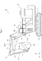
- Fig. 1 is a side view of a hydraulic excavator equipped with a movement identification device 100 according to Embodiment 1 of the present disclosure.
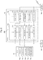
- Fig. 2 is a block diagram of the movement identification device 100 mounted on the hydraulic excavator 10 of Fig. 1 .
- Fig. 3 is a block diagram showing an example of the configuration of a hydraulic drive system 17 in the hydraulic excavator 10 of Fig. 1 .
- the movement identification device 100 of the present embodiment has the following structure as its main features.
- the movement identification device 100 includes a waveform generation unit 111, a waveform storage unit 121, and a motion identification unit 112.
- the waveform generation unit 111 generates a force waveform based on the signal of a force sensor that detects the force acting on the construction machine and an attitude waveform based on the signal of an attitude sensor that detects the attitude of the construction machine.
- the waveform storage unit 121 stores reference waveforms Wr1, Wr2, and Wr3 (see Fig. 5 ), which are combinations of force waveforms and attitude waveforms corresponding to specific motions of the construction machine.
- the motion identification unit 112 compares a motion waveform Wm (see Fig.
- the construction machine in which the specific motion is identified by the movement identification device 100 is not particularly limited.
- the construction machine is a hydraulic excavator 10, for example.
- the hydraulic excavator 10 is a supersized hydraulic excavator used in mines.
- the hydraulic excavator 10 shown in Fig. 1 is a backhoe.
- the construction machine in which the specific motion is identified by the movement identification device 100 can be a loader. The following firstly describes an example of the configuration of the hydraulic excavator 10 that is one example of the construction machine, and then describes the configuration of each unit of the movement identification device 100 of the present embodiment in details.
- the hydraulic excavator 10 includes a lower traveling body 11, an upper slewing body 12, a cab 13, a front working machine 14, and a controller 15.
- the hydraulic excavator 10 also includes a sensor 18, a transmitter 19A, and a monitor 19B shown in Fig. 2 , and an operating lever 13a and a hydraulic drive system 17 shown in Fig. 3 .
- the following may describe each part of the hydraulic excavator 10 with reference to a three-dimensional orthogonal coordinate system having X-axis parallel to the front-rear direction of the hydraulic excavator 10, Y axis parallel to the width direction of the hydraulic excavator 10, and Z axis parallel to the height direction of the hydraulic excavator 10.
- the lower traveling body 11 has a traveling device 11a with a pair of crawlers in the width direction (Y direction) of the hydraulic excavator 10.
- the lower traveling body 11 driven by the hydraulic drive system 17 causes traveling of the hydraulic excavator 10.
- the upper slewing body 12 is mounted on the lower traveling body 11 to be able to swivel.
- the upper slewing body 12 is driven by a hydraulic motor or an electric motor, which are not shown, and swivels relative to the lower traveling body 11 around a rotary shaft parallel to the height direction (Z direction) of the hydraulic excavator 10.
- the upper slewing body 12 houses various devices such as an engine (not shown), a hydraulic pump, and a plurality of valves, described later.
- the cab 13 is a cabin of the hydraulic excavator 10, in which a driver's seat for an operator who manipulates the hydraulic excavator 10 is housed. In one example, the cab 13 is placed above the front portion of the upper slewing body 12 to be adjacent to the front working machine 14.
- the front working machine 14 is provided on the front side of the upper slewing body 12 and driven by the hydraulic drive system 17 and performs works such as digging.
- the front working machine 14 has a boom 14a, an arm 14b, and a bucket 14c.
- the boom 14a has a proximal end that connects to the upper slewing body 12 via a rotary shaft parallel to the width direction (Y direction) of the hydraulic excavator 10.
- the boom 14a is driven by an actuator and rotates in a predetermined angular range around the rotary shaft mounted to the upper slewing body 12.
- a hydraulic cylinder 1 is used as the actuator to drive the boom 14a.
- the hydraulic cylinder 1 is a hydraulic actuator driven by hydraulic oil supplied.
- the hydraulic cylinder 1 has a cylinder tube 1a, a piston 1b, and a rod 1c.
- the hydraulic cylinder 1 is a single-rod hydraulic cylinder having the rod 1c protruding to one side of the cylinder tube 1a.
- the hydraulic cylinder 1 that drives the boom 14a may be referred to as a boom cylinder 1A, for example.
- one end of the cylinder tube 1a is connected to an intermediate portion of the boom 14a via a rotary shaft parallel to the width direction (Y direction) of the hydraulic excavator 10.
- the piston 1b is housed in the cylinder tube 1a and slides in the axial direction of the rod 1c along the inner peripheral face of the cylinder tube 1a.
- One end of the rod 1c is connected to the piston 1b inside the cylinder tube 1a.
- the other end of the rod 1c extends externally from the inside of the cylinder tube 1A and is connected to the upper slewing body 12 via a rotary shaft parallel to the width direction (Y direction) of the hydraulic excavator 10.
- the arm 14b has a proximal end that connects to the distal end of the boom 14a via a rotary shaft parallel to the width direction (Y direction) of the hydraulic excavator 10.
- the arm 14b is driven by an actuator and rotates in a predetermined angular range around the rotary shaft mounted to the boom 14a.
- a hydraulic cylinder 1 is used as the actuator to drive the arm 14b.
- the hydraulic cylinder 1 driving the arm 14b may be referred to as an arm cylinder 1B, for example.
- one end of the cylinder tube 1a is connected to an intermediate portion of the boom 14a via a rotary shaft parallel to the width direction (Y direction) of the hydraulic excavator 10.
- the other end of the rod 1c which is on the other side of the end connecting to the piston 1b, is connected to the proximal end of the arm 14b via a rotary shaft parallel to the width direction (Y direction) of the hydraulic excavator 10.
- the rod 1c of the arm cylinder 1B is connected to the proximal end side of the arm 14b more than the distal end of the boom 14a.
- the bucket 14c has a proximal end that connects to the distal end of the arm 14b via a rotary shaft parallel to the width direction (Y direction) of the hydraulic excavator 10.
- the bucket 14c is driven by an actuator and rotates in a predetermined angular range around the rotary shaft mounted to the arm 14b.
- a hydraulic cylinder 1 similar to the boom cylinder 1A is used as the actuator to drive the bucket 14c.
- the hydraulic cylinder 1 that drives the bucket 14c may be referred to as a bucket cylinder 1C, for example.
- one end of the cylinder tube 1a is connected to the proximal end of the arm 14b, for example, via a rotary shaft parallel to the width direction (Y direction) of the hydraulic excavator 10.
- the other end of the rod 1c which is on the other side of the end connecting to the piston 1b, is connected to the proximal end of the bucket 14c via a link, for example.
- the link is connected to the rod 1c via a rotary shaft parallel to the width direction (Y direction) of the hydraulic excavator 10.
- the controller 15 is housed in the upper slewing body 12, and controls the hydraulic drive system 17 based on the pilot pressure in accordance with the operation with the operating lever 13a in the cab 13 and a signal from the sensor 18 mounted to the hydraulic excavator 10.
- the controller 15 is a computer unit including a calculation unit 15a such as a central processing unit, a memory 15b such as RAM and ROM, programs stored in the memory 15b, and an input/output unit for inputting/outputting signals.
- the controller 15 is constituting the movement identification device 100 of the present embodiment. The details of the movement identification device 100 are described later. In one example, the movement identification device 100 may be provided separately from the controller 15 that controls the hydraulic drive system 17. In one example, the movement identification device 100 is connected to the sensor 18, the transmitter 19A, and the monitor 19B via a network such as a control area network (CAN).
- CAN control area network
- the hydraulic drive system 17 includes a hydraulic cylinder 1, a hydraulic pump 2, a pilot pump 3, a bottom-pressure sensor 4a, an operating-pressure sensor 4b, a hydraulic oil tank 5, and an engine 6.
- the hydraulic drive system 17 also includes a directional control valve V1, a variable throttle V2, and a variable throttle control valve V3.
- the hydraulic excavator 10 is equipped with three hydraulic cylinders 1: a boom cylinder 1A, an arm cylinder 1B and a bucket cylinder 1C. These cylinders 1 have a similar configuration. Therefore Fig. 3 shows one of the hydraulic cylinders 1, and omits the other two hydraulic cylinders 1.
- the hydraulic cylinder 1 has the cylinder tube 1a, the piston 1b, and the rod 1c.
- the interior of the cylinder tube 1a is divided by the piston 1b into a bottom-side oil chamber 1e located close to the proximal end of the cylinder tube 1a and a rod-side oil chamber If located close to the distal end of the cylinder tube 1a.
- the piston 1b of the hydraulic cylinder 1 moves to the distal end of the cylinder tube 1a. Then the hydraulic oil is discharged from the rod-side oil chamber If, so that the rod 1c extends. In response to supplying of hydraulic oil into the rod-side oil chamber If, the piston 1b of the hydraulic cylinder 1 moves to the proximal end of the cylinder tube 1a. Then the hydraulic oil is discharged from the bottom-side oil chamber 1e, so that the rod 1c contracts.
- extension of the rod 1c of the boom cylinder 1A rotates the boom 14a around the rotary shaft at the proximal end of the boom 14a, and moves the distal end of the boom 14a upward in the height direction (Z direction) of the hydraulic excavator 10.
- Contraction of the rod 1c of the boom cylinder 1A rotates the boom 14a around the rotary shaft at the proximal end of the boom 14a, and moves the distal end of the boom 14a downward in the height direction (Z direction) of the hydraulic excavator 10.
- Extension of the rod 1c of the arm cylinder 1B rotates the arm 14b around the rotary shaft at the proximal end of the arm 14b, and moves the distal end of the arm 14b downward in the height direction (Z direction) of the hydraulic excavator 10.
- Contraction of the rod 1c of the arm cylinder 1B rotates the arm 14b around the rotary shaft at the proximal end of the arm 14b, and moves the distal end of the arm 14b upward in the height direction (Z direction) of the hydraulic excavator 10.
- Extension of the rod 1c of the bucket cylinder 1C rotates the bucket 14c around the rotary shaft at the proximal end of the bucket 14c, and moves the distal end of the bucket 14c upward in the height direction (Z direction) of the hydraulic excavator 10.
- Contraction of the rod 1c of the bucket cylinder 1C rotates the arm 14b around the rotary shaft at the proximal end of the bucket 14c, and moves the distal end of the bucket 14c downward in the height direction (Z direction) of the hydraulic excavator 10.
- the hydraulic pump 2 is a variable capacity hydraulic pump of the swash plate type, radial piston type or bent axis type.
- the hydraulic pump 2 is rotatably driven by the engine 6.
- the hydraulic pump 2 has a variable capacity portion 2a including a swash plate, a bent axis, or the like, and a variable volume mechanism 2b that drives the variable capacity portion 2a.
- the variable volume mechanism 2b drives the variable capacity portion 2a based on the instruction of the controller 15. This changes the tilt angle of the variable capacity portion 2a to increase or decrease the pump capacity of the hydraulic pump 2.
- the hydraulic pump 2 discharges pressure oil into the discharge pipeline.
- the discharge pipeline branches into a center bypass pipeline and a branch pipeline at a position upstream of the directional control valve VI.
- the pilot pump 3 is a fixed capacity hydraulic pump.
- the pilot pump 3 is also rotatably driven by the engine 6.
- the pilot pump 3 discharges pilot pressure oil into the pilot pipeline.
- the pilot pipeline branches into the throttle pilot pipeline for supplying pilot pressure oil to the variable throttle control valve V3 at a position upstream of the operating lever 13a.
- the directional control valve VI switches the pressure oil supplied from the hydraulic pump 2 to the hydraulic cylinder 1 to control the supply and discharge of the pressure oil at the hydraulic cylinder 1.
- the directional control valve VI includes a hydraulic pilot type directional control valve with 6 ports and 3 positions.
- the directional control valve VI is connected to the hydraulic pump 2 via the discharge pipeline, and is connected to the hydraulic oil tank 5 via the center bypass pipeline and the return pipeline.
- the directional control valve VI is also connected to the bottom-side oil chamber 1e of the hydraulic cylinder 1 via the bottom-side pipeline and to the rod-side oil chamber If of the hydraulic cylinder 1 via the rod-side pipeline.
- the variable throttle V2 is located downstream of the directional control valve VI in the middle of the center bypass pipeline.
- the variable throttle V2 variably throttles the flow area of the center bypass pipeline at a position downstream of the directional control valve VI.
- the variable throttle V2 is controlled by the pilot pressure oil supplied from the variable throttle control valve V3.
- the variable throttle V2 has a smaller flow channel area with a larger pilot pressure from the variable throttle control valve V3, and has a larger flow channel area with a smaller pilot pressure.
- the pilot pressure of the variable throttle control valve V3 is variably controlled by the controller 15.
- the bottom pressure sensor 4a detects the pressure of the pressure oil in the bottom-side oil chamber 1e of the hydraulic cylinder 1. In one example, the bottom pressure sensor 4a detects the pressure of the bottom-side oil chamber 1e or the bottom-side pipeline.
- the bottom pressure sensor 4a is connected to the controller 15 via a signal line, and outputs a detection signal corresponding to the detected pressure of the bottom-side oil chamber 1e to the controller 15.
- the operating pressure sensor 4b detects the displacement of the operating lever 13a.
- the operating pressure sensor 4b is placed in the lowering-side pilot pipeline.
- the operating pressure sensor 4b detects the hydraulic pressure in the lowering-side pilot pipeline, that is, the pilot pressure for lowering the boom.
- the operating pressure sensor 4b is connected to the controller 15 via a signal line and detects the pilot pressure of the boom lowering corresponding to the manipulation amount of boom lowering.
- the operating pressure sensor 4b outputs a detection signal corresponding to the pilot pressure of the boom lowering to the controller 15.
- the sensor 18 is attached to a part of the hydraulic excavator 10, and detects physical quantities and outputs them to the controller 15.
- the sensor 18 includes a force sensor that detects a force acting on the hydraulic excavator 10, which is a construction machine, and an attitude sensor that detects the attitude of the hydraulic excavator 10, for example.
- the sensor 18 includes a hydraulic sensor 18b as the force sensor, and an angle sensor 18a, an angular rate sensor 18c, an acceleration sensor 18d, an inclination angle sensor 18e, and a not-shown stroke sensor as the attitude sensors.
- the stroke sensor detects the strokes of the boom cylinder 1A, the arm cylinder 1B, and the bucket cylinder 1C.
- the hydraulic sensor 18b detects the hydraulic pressure in the hydraulic cylinder 1 of the hydraulic excavator 10, i.e., the pressure of the hydraulic oil in the bottom-side oil chamber 1e. Specifically, the hydraulic sensor 18b detects the pressure of the hydraulic oil in the bottom-side oil chamber 1e of each of the boom cylinder 1A, the arm cylinder 1B, and the bucket cylinder 1C.
- the hydraulic sensor 18b may be the bottom pressure sensor 4a described above, for example.
- the hydraulic sensor 18b detects the pressure of the hydraulic oil of the hydraulic motor.
- the angle sensor 18a detects the rotating angle of various parts of the construction machine. Specifically, the angle sensor 18a detects the rotating angle of the upper slewing body 12 of the hydraulic excavator 10 and of various parts of the front working machine 14, for example. More specifically, this angle sensor 18a is placed at each of the rotary shaft of the upper slewing body 12, the rotary shaft at the proximal end of the boom 14a, the rotary shaft at the proximal end of the arm 14b, and the rotary shaft at the proximal end of the bucket 14c.
- the angle sensor 18a detects the rotation angle of the upper slewing body 12 relative to the lower traveling body 11, the rotation angle of the boom 14a relative to the upper slewing body 12, the rotation angle of the arm 14b relative to the boom 14a, and the rotation angle of the bucket 14c relative to the arm 14b.
- the angular rate sensor 18c is attached to each of the upper slewing body 12, the boom 14a, the arm 14b, and the bucket 14c, and detects the angular rates of the upper slewing body 12, the boom 14a, the arm 14b and the bucket 14c.
- the acceleration sensor 18d is attached to each of the upper slewing body 12, the boom 14a, the arm 14b, and the bucket 14c, and detects the accelerations of the upper slewing body 12, the boom 14a, the arm 14b and the bucket 14c.
- the inclination angle sensor 18e is attached to each of the upper slewing body 12, the boom 14a, the arm 14b, and the bucket 14c, and detects the inclination angles of the upper slewing body 12, the boom 14a, the arm 14b and the bucket 14c.
- the transmitter 19A is connected to the controller 15, and transmits information on the motion of the hydraulic excavator 10 and a fatigue index value output from the controller 15 to the outside.
- the transmitter 19A may transmit identification information on the hydraulic excavator 10.
- the hydraulic excavator 10 may be equipped with a positioning device such as a global navigation satellite system (GNSS). In this case, the transmitter 19A may transmit the position information on the hydraulic excavator 10.
- GNSS global navigation satellite system
- the monitor 19B is a display device such as a liquid crystal display device or an organic EL display device placed in the cab 13.
- the monitor 19B may include an input device, such as a touch panel.
- the monitor 19B displays information on the motion of the hydraulic excavator 10 and a fatigue index value output from the controller 15.
- the directional control valve VI of the hydraulic excavator 10 moves by the pressure oil from the pilot pump 3, and the pressure oil of the hydraulic pump 2 is guided to the bottom-side oil chamber 1e or the rod-side oil chamber If of the hydraulic cylinder 1.
- the hydraulic excavator 10 expands or contracts the rods 1c of the boom cylinder 1A, the arm cylinder 1B, and the bucket cylinder 1C according to the displacement of the operating lever 13a as described above to operate each part of the boom 14a, the arm 14b, and the bucket 14c.
- the controller 15 controls the hydraulic motor or the electric motor between the lower traveling body 11 and the upper slewing body 12 in accordance with the operation signal from the operating lever 13a.
- the hydraulic excavator 10 swivels the upper slewing body 12 relative to the lower traveling body 11 in accordance with the displacement of the operating lever 13a.
- the movement identification device 100 of the present embodiment includes a motion storage unit 122 in addition to the waveform generation unit 111, the motion identification unit 112, and the waveform storage unit 121 as stated above.
- the movement identification device 100 of the present embodiment also includes a stress calculation unit 113, a damage degree calculation unit 114, and an index value calculation unit 115.
- the movement identification device 100 of the present embodiment also includes a calculation expression storage unit 123, a S-N curve storage unit 124, and an index value storage unit 125.
- the movement identification device 100 of the present embodiment may be configured with the controller 15 mounted on the hydraulic excavator 10.
- the controller 15 does not necessarily have to be mounted on the construction machine, and may be provided outside the construction machine.
- the controller 15 may include an information terminal that can receive information of the sensor 18 via a transmitter 19A from the hydraulic excavator 10, for example.
- the waveform generation unit 111 generates a force waveform based on the signal of a force sensor that detects the force acting on the construction machine and an attitude waveform based on the signal of an attitude sensor that detects the attitude of the construction machine.
- the waveform generation unit 111 generates a force waveform, which is the time-series data of pressure, based on the signal of the hydraulic sensor 18b that detects the pressure acting on the hydraulic oil inside the hydraulic cylinder 1 of the hydraulic excavator 10, for example.
- the waveform generation unit 111 also generates an attitude waveform, which is the time-series data of the rotating angles of various part of the hydraulic excavator 10, based on the signal of the angle sensor 18a that detects the rotating angle of each part, for example.
- the waveform generation unit 111 may generate a force waveform and an attitude waveform based on the signal of a sensor other than the angle sensor 18a and the hydraulic sensor 18b included in the sensor 18.
- the waveform generation unit 111 may also perform appropriate pre-processing on the generated force waveform and attitude waveform, such as noise removal and gain adjustment.
- Fig. 5 shows one example of the reference waveforms Wr1, Wr2, and Wr3 stored in the waveform storage unit 121.
- the three waveforms with different line types are waveform data based on signals from different sensors, including at least one force sensor and at least one attitude sensor.
- Fig. 5 shows one reference waveform Wr1, Wr2, or Wr3 for each motion of the hydraulic excavator 10. Note that, in reality, the reference waveform of each motion of the hydraulic excavator 10 includes a plurality of reference waveforms corresponding to various joints and various components of the hydraulic excavator 10, for example.
- the waveform storage unit 121 stores reference waveforms Wr1, Wr2, and Wr3, which are combinations of force waveforms and attitude waveforms corresponding to specific motions of the construction machine.
- the waveform storage unit 121 stores a plurality of reference waveforms Wr1, Wr2, and Wr3 corresponding to a plurality of different specific motions.
- the waveform storage unit 121 stores the reference waveforms Wr1, Wr2, and Wr3, including the reference waveform Wr1 corresponding to the downward excavation of the hydraulic excavator 10, the reference waveform Wr2 corresponding to the upward excavation, and the reference waveform Wr3 corresponding to the leveling.
- the reference waveform Wr1 of the downward excavation is the reference waveform of the motion in which the hydraulic excavator 10 excavates below the cab 13, for example.
- the reference waveform Wr2 of the upward excavation is the reference waveform of the motion in which the hydraulic excavator 10 excavates above the cab 13, for example.
- the reference waveform Wr3 of the leveling is the reference waveform of the motion in which the hydraulic excavator 10 levels earth and crushed stone to be flat, for example.
- the motions corresponding to the reference waveforms stored in the waveform storage unit 121 are not particularly limited, and the waveform storage unit 121 can store any number of reference waveforms corresponding to arbitrary motions.
- Fig. 6 shows one example of the identification result of specific motions by the motion identification unit 112.
- the combination of the waveforms of sensor signal A shown by the solid line, the sensor signal B shown by the broken line, and the sensor signal C shown by the dashed-dotted line is the motion waveform Wm of the hydraulic excavator 10.
- the motion waveform Wm is a combination of at least one force waveform and at least one attitude waveform, corresponding to an arbitrary motion of the hydraulic excavator 10.
- the motion identification unit 112 compares a motion waveform Wm, which is a combination of a force waveform and an attitude waveform corresponding to an arbitrary motion of a construction machine, with reference waveforms Wr1, Wr2, and Wr3 stored in the waveform storage unit 121 to identify a specific motion in the arbitrary motion. Specifically, the motion identification unit 112 compares the motion waveform Wm corresponding to an arbitrary motion of the hydraulic excavator 10 with the reference waveforms Wr1, Wr2, and Wr3 of the specific motions shown by the circled numbers 1 to 3 in Fig. 5 , to identify a specific motion included in the arbitrary motion.
- a motion waveform Wm which is a combination of a force waveform and an attitude waveform corresponding to an arbitrary motion of a construction machine
- the motion identification unit 112 performs pattern matching of a part of the motion waveform Wm and the reference waveforms Wr1, Wr2, and Wr3 sequentially to identify the specific motions included in the motion waveform Wm, i.e., the motions of the circled numbers 1 to 3 shown in Fig. 5 .
- the motion identification unit 112 identifies two times of the downward excavation indicated by the circled number 1, one time of the upward excavation indicated by the circled number 2, and one time of the leveling indicated by the circled number 3, from the motion waveform Wm of the hydraulic excavator 10 for a predetermined period.
- the motion identification unit 112 outputs specific motions identified from the motion waveform Wm, including downward excavation, upward excavation, and leveling, to the monitor 19B and the motion storage unit 122.
- the motion identification unit 112 obtains the operating time of the hydraulic excavator 10 and the number of specific motions identified during that operating time based on the motion waveform Wm, and outputs them to the monitor 19B and the motion storage unit 122.
- the motion identification unit 122 obtains the number of the specific motions per unit time based on the motion waveform Wm, and outputs it to the monitor 19B and the motion storage unit 122.
- the motion storage unit 122 stores specific motions of the hydraulic excavator 10 output from the motion identification unit 112. In one example, the motion storage unit 122 stores the operating time of the hydraulic excavator 10 and the number of specific motions identified during that operating time output from the motion identification unit 112. In one example, the motion storage unit 122 stores the number of specific motions per unit time output from the motion identification unit 112.
- the stress calculation unit 113 calculates stress acting on a plurality of portions of the construction machine based on the outputs of the force sensor that detects a force acting on the construction machine and an attitude sensor that detects the attitude of the construction machine. Specifically, in one example, the stress calculation section 113 calculates the stress acting on a plurality of portions of each of the boom 14a, the arm 14b, and the bucket 14c of the hydraulic excavator 10 based on the outputs of the sensors 18 attached to the boom 14a, the arm 14b, and the bucket 14c. Although not particularly limited, tens to hundreds of portions may be set for each component.
- the stress calculation unit 113 calculates the stress acting on a plurality of portions of each component constituting the hydraulic excavator 10 using a stress calculation expression stored in advance in the calculation expression storage unit 123, for example.
- the stress calculation expression represents the relationship between the outputs of the sensor 18 and the stress acting on a plurality of portions of the components of the hydraulic excavator 10.
- the stress calculation expression is obtained in advance for each portion of the components of the hydraulic excavator 10 using a multiple regression equation or a regression equation using machine learning, and is stored in the calculation expression storage unit 123.
- ⁇ 1 , ⁇ 2 , ... denote stresses acting on a plurality of portions of the components of the hydraulic excavator 10.
- s 1 , s 2 , ... denote the outputs of the sensors 18, M, N and A are constants based on the characteristics of these portions, and t denotes the time.
- the stress calculation equations may be obtained in advance, whereby the stress acting on each of many portions of the components of the hydraulic excavator 10 and the time-history stress waveforms can be easily obtained by simple calculations based on the output of the sensor 18.
- the damage degree calculation unit 114 calculates the cumulative damage degree at each portion based on the stress acting on the portion calculated by the stress calculation unit 113. Specifically, the damage degree calculation unit 114 calculates the cumulative damage degree D at each portion of the components based on the time-history stress waveform acting on the portion of the components of the hydraulic excavator 10 and the S-N curve of the stress amplitude and the number of repetitions that is stored in advance in the S-N curve storage unit 124.
- the cumulative damage degree can be calculated by the Miner's law shown in expression (4) below or the modified Miner's law, following the frequency analysis of the time-history stress waveform by the range-pair counting, the peak valley method, or the rainflow counting.
- the index value calculation unit 115 calculates a fatigue index value, which is a weighted value of the cumulative damage degree calculated by the damage degree calculation unit 114, for each portion of the components of the hydraulic excavator 10.
- the fatigue index value is obtained by assigning the weighting according to the usage environment, material properties, and other factors for each component and each portion of the hydraulic excavators 10 to the cumulative damage degree calculated for each portion of the components of the hydraulic excavator 10.
- the fatigue index value indicates the degree of fatigue and is represented by an integer increasing from 1, for example.
- i 1 , i 2 , ... denote fatigue index values of each portion of the components
- a denotes an arbitrary coefficient
- w a1 , w a2 , ... and w b1 , w b2 , ... and b 1 , b 2 , ... denote numerical values for weighting specific to each portion of the components of the hydraulic excavator 10.
- d 1 , d 2 , ... denote the cumulative damage degree of each portion of the components.
- i 1 i 2 ⁇ a w a 1 0 ⁇ 0 w a 2 ⁇ ⁇ ⁇ ⁇ w b 1 0 ⁇ 0 w b 2 ⁇ ⁇ ⁇ ⁇ ⁇ d 1 d 2 ⁇ + b 1 b 2 ⁇
- weightings w a1 , w a2 , ..., w b1 , w b2 , ... and b 1 , b 2 , ... according to the operating environment, material properties, and other conditions for each hydraulic excavator 10, each component, and each portion are stored in the memory 15b, together with the calculation expression such as expression (5).
- a user or a seller of the hydraulic excavator 10 can freely change these weightings by inputting information to the input device of the monitor 19B or the input device of an information terminal (not shown) according to the individual request or environment.
- the index value calculation unit 115 uses the calculation expression as shown in expression (5), for example, to calculate the fatigue index values i 1 , i 2 , ... from the cumulative damage degree d 1 , d 2 , ... calculated by the damage degree calculation unit 114.
- the movement identification device 100 of the present embodiment may further include a comparison unit that compares a degree of fatigue based on time series data of the fatigue index value.
- the comparison unit may be part of the index value calculation unit 115.
- the index value calculation unit 115 may also function as the comparison unit that compares a degree of fatigue based on time series data of the fatigue index value.
- the index value calculation unit 115 functioning as the comparison unit outputs the comparison result of the degree of fatigue to the monitor 19B and the index value storage unit 125, for example.
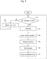
- FIG. 4 is a flowchart showing an example of the processing by the movement identification device 100 of Fig. 2 .
- the movement identification device 100 starts generating a force waveform and an attitude waveform by the waveform generation unit 111 and calculating the fatigue index value by the stress calculation unit 113.
- the waveform generation unit 111 and the stress calculation unit 113 perform determination process P1 as to whether or not the data acquired from the sensor 18 includes not-calculated data. Specifically, in the determination process P1, the waveform generation unit 111 and the stress calculation unit 113 search for the data acquired from the sensor 18. If there is new data that has not been processed in the past (YES), these units perform process P2 to read the data. In the determination process P1, if there is no new data that has not been processed in the past (NO), the waveform generation unit 111 and the stress calculation unit 113 perform process P3 that waits for a certain period of time, and then return to the determination process P1.
- the waveform generation unit 111 After reading data in the process P2, the waveform generation unit 111 performs process P4 to read reference waveforms Wr1, Wr2, and Wr3 as shown in Fig. 5 from the waveform storage unit 121.
- the stress calculation unit 113 performs the process of selecting one evaluation point that has not undergone calculation from the plurality of evaluation points corresponding to the plurality of portions of the components of the hydraulic excavator 10. For this process, all the evaluation points have individual numbers assigned, and the stress calculation unit 113 selects the not-calculated evaluation points in ascending order one by one starting from the evaluation point with the smallest number.
- the waveform generation unit 111 After the end of the process P4, the waveform generation unit 111 generates a force waveform and an attitude waveform based on the data read in the process P2, and performs process P5 to generate a motion waveform Wm corresponding to an arbitrary motion of the hydraulic excavator 10.
- the stress calculation unit 113 uses the above-described calculation expressions (1) to (3) and the data read at the process P2, for example, to perform process that calculates a time-series stress waveform at the selected evaluation point, that is, a time-history stress waveform.
- the motion identification unit 112 compares the motion waveform Wm generated in the process P5 with the reference waveforms Wr1, Wr2, and Wr3 read in the process P4. Then, as shown in Figs. 5 and 6 , the motion identification unit 112 performs process P6 to identify a specific motion of the hydraulic excavator 10 from the motion waveform Wm corresponding to the arbitrary motion of the hydraulic excavator 10. Examples of the specific motion include downward excavation of the circled number 1, upward excavation of the circled number 2, and leveling of the circled number 3.
- the damage degree calculation unit 114 performs the process that calculates the cumulative damage degree at the selected evaluation point based on the time-history stress waveform calculated by the stress calculation unit 113 as described above.
- the index value calculation unit 115 then performs the process that calculates the fatigue index value of the selected evaluation point using the cumulative damage degree calculated by the damage degree calculation unit 114 as described above.
- the motion identification unit 112 performs process P7 that outputs the specific motion identified from the motion waveform Wm to the monitor 19B and the motion storage unit 122.
- the motion identification unit 112 outputs the specific motion as well as the operating time of the hydraulic excavator 10, the number of the specific motions identified during that operating time, and the number of the specific motions per unit time to the monitor 19B and the motion storage unit 122.
- the determination process P1 to the process P7 can be repeated from turning-on of the start switch of the hydraulic excavator 10 to turning-off of the switch. Tables 1 and 2 below show an example of the information displayed on the monitor 19B.
- the monitor 19B can display information of machines A to D as shown below.
- the information on each machine may be transmitted to an external management device, for example, by the transmitter 19B, and the operator can confirm the status of a plurality of hydraulic excavators as shown in Tables 1 and 2 below.
- the movement identification device of the present embodiment identifies a specific motion from an arbitrary motion of the hydraulic excavator 10 to clarify the unbalanced state in motion of each hydraulic excavator 10.
- the device can issue an alarm, for example, to recommend inspection of the machine.
- the index value calculation unit 115 determines whether or not the fatigue index value has been calculated for all the evaluation points. If the result of the determination shows that the calculation of all the evaluation points has not been completed, the index value calculation unit 115 returns to the process that selects one of the not-calculated evaluation points. If the result of the determination shows that the calculation of all the evaluation points is completed, the index value calculation unit 115 determines whether the fatigue index value exceeds a threshold of each evaluation point stored in the memory 15b, for example.
- the index value calculation unit 115 may compare the fatigue index value of each of the evaluation points with the threshold of the evaluation point, or may compare the fatigue index value of each of a plurality of evaluation points selected in advance with the threshold of the selected evaluation point. If the result of the determination shows that the fatigue index value exceeds the threshold at any evaluation point, then the index value calculation unit 115 may send an alarm recommending inspection of the portion corresponding to the evaluation point to the information terminal via the transmitter 19A or may display it on the monitor 19B, for example.
- the index value calculation unit 115 performs the process of outputting the fatigue index values of all the evaluation points to the monitor 19B and the memory 15b, and the procedure returns to the determination process P1.
- the determination process P1 to the process of outputting the fatigue index values can be repeated from turning-on of the start switch of the hydraulic excavator 10 to turning-off of the switch.
- the movement identification device 100 of the present embodiment includes the waveform generation unit 111, the waveform storage unit 121, and the motion identification unit 112.
- the waveform generation unit 111 generates a force waveform based on the signal of a force sensor that detects the force acting on the construction machine and an attitude waveform based on the signal of an attitude sensor that detects the attitude of the construction machine.
- the waveform storage unit 121 stores reference waveforms Wr1, Wr2, and Wr3, which are combinations of force waveforms and attitude waveforms corresponding to specific motions of the construction machine.
- the motion identification unit 112 compares a motion waveform Wm, which is a combination of a force waveform and an attitude waveform corresponding to an arbitrary motion of a construction machine, with reference waveforms Wr1, Wr2, and Wr3 stored in the waveform storage unit 121 to identify a specific motion in the arbitrary motion of the hydraulic excavator 10.
- Wm a motion waveform
- Wr1, Wr2, and Wr3 stored in the waveform storage unit 121 to identify a specific motion in the arbitrary motion of the hydraulic excavator 10.
- the present embodiment provides the movement identification device 100 capable of identifying a specific motion of the hydraulic excavator 10, such as downward excavation, upward excavation, and leveling, based on the outputs of the angle sensor 18a and the hydraulic sensor 18b of the hydraulic excavator 10 from an arbitrary motion of the hydraulic excavator 10 with higher accuracy than conventional technology.
- the conventional excavator support device as described above is configured so that the management device estimates the work content of the excavator based on the time history of the attitude of the attachment. Therefore, the management device might erroneously estimate the work content based on the time history of the attachment attitude similar to the work content of the excavator, even when the excavator is not actually performing that work.
- the movement identification device 100 of the present embodiment is configured so that the waveform generation unit 111 generates a force waveform based on the signal of the hydraulic sensor 18b that detects the hydraulic pressure acting on the hydraulic cylinder 1 of the hydraulic excavator 10 and an attitude waveform based on the signal of the angle sensor 18a that detects the rotation angle of each part of the hydraulic excavator 10.
- the waveform storage unit 121 stores reference waveforms Wr1, Wr2, and Wr3, which are combinations of force waveforms and attitude waveforms corresponding to specific motions of the hydraulic excavator 10.
- the motion identification unit 112 compares a motion waveform Wm, which is a combination of a force waveform and an attitude waveform corresponding to an arbitrary motion of the hydraulic excavator 10, with the reference waveforms Wr1, Wr2, and Wr3 stored in the waveform storage unit 121 to identify a specific motion in the arbitrary motion of the hydraulic excavator 10.
- the force waveform based on the signal of the hydraulic sensor 18b included in the motion waveform Wm of the hydraulic excavator 10 will be different from the force waveform included in the reference waveforms Wr1, Wr2, and Wr3.
- the attitude waveform based on the signal of the angle sensor 18a included in the motion waveform Wm may be similar to or the same as the attitude waveform included in the reference waveforms Wr1, Wr2, and Wr3.
- the present embodiment prevents erroneous identification of a specific motion.
- the movement identification device 100 of the present embodiment is capable of identifying a type of a motion of the hydraulic excavator 10 based on the outputs of the sensor 18 attached to the hydraulic excavator 10 with higher accuracy than conventional technology.
- the movement identification device 100 of the present embodiment is configured so that the waveform storage unit 121 stores a plurality of different reference waveforms Wr1, Wr2, and Wr3 corresponding to a plurality of different specific motions.
- This configuration allows the movement identification device to identify a plurality of specific motions corresponding to the plurality of reference waveforms Wr1, Wr2, and Wr3 from an arbitrary motion of the hydraulic excavator 10.
- Simply storing a reference waveform corresponding to a new specific motion in the waveform storage unit 121 allows the movement identification device to easily identify the new specific motion from an arbitrary motion of the hydraulic excavator 10.
- the force sensor that detects a force acting on the construction machine is the hydraulic sensor 18b that measures the hydraulic pressure in the hydraulic cylinder 1 of the construction machine.
- the bottom pressure sensor 4a conventionally provided in the hydraulic drive system 17 of the hydraulic excavator 10 can be used as the hydraulic sensor 18b, for example.
- the present embodiment does not require the installment of a sensor such as a strain gauge just for measuring the force.
- the movement identification device 100 therefore can be easily used for a construction machine, such as the hydraulic excavator 10. Further, the stress acting on each part of the hydraulic excavator 10 can be calculated more accurately based on the output of the hydraulic sensor 18b.
- the attitude sensor that detects the attitude of the construction machine is the angle sensor 18a that detects the rotation angle of each part of the construction machine.
- the attitude sensor that detects the attitude of the hydraulic excavator 10 in the movement identification device 100 of the present embodiment is the angle sensor 18a that detects the relative rotation angles between the lower traveling body 11 and the upper slewing body 12, the upper slewing body 12 and the boom 14a, the boom 14a and the arm 14b, and the arm 14b and the bucket 14c.
- the angle sensor 18a conventionally provided in the hydraulic excavator 10 can be used as the attitude sensor, for example.
- the movement identification device 100 therefore can be easily used for a construction machine, such as the hydraulic excavator 10. Further, the stress acting on each part of the hydraulic excavator 10 can be calculated more accurately based on the output of the angle sensor 18a.
- the attitude sensor that detects the attitude of the construction machine includes the acceleration sensor 18d. This configuration enables measurement of the attitude of the construction machine more correctly and identification of the type of a motion of the construction machine more accurately.
- the movement identification device 100 of the present embodiment includes the stress calculation unit 113, the damage degree calculation unit 114, and the index value calculation unit 115.
- the stress calculation unit 113 calculates stress acting on a plurality of portions of the construction machine based on the outputs of the force sensor and the attitude sensor.
- the damage degree calculation unit 114 calculates the cumulative damage degree of each portion of the construction machine based on the stress calculated by the stress calculation unit 113.
- the index value calculation unit 115 calculates a fatigue index value, which is a weighted value of the cumulative damage degree, for each portion.
- This configuration enables the movement identification device 100 to manage the fatigue of each portion of the construction machine more accurately than the conventional systems, according to the conditions specific to each construction machine, each component of the construction machine, and each of a plurality of portions of the components, for example.
- the cumulative damage degree directly used in the conventional excavator support device is based on the linear cumulative damage rule, which is an empirical rule, and assumes that the object will undergo fatigue fracture when the cumulative damage degree reaches 1.
- the cumulative damage degree is a value that inherently includes fluctuations, and in reality, an object may undergo fatigue failure before the cumulative damage degree reaches 1, or the object may not undergo fatigue failure even if the cumulative damage degree exceeds 1.
- the conventional excavator support device which uses the cumulative damage degree as it as, may fail to appropriately set the inspection timing for each excavator part.
- the movement identification device 100 of the present embodiment is configured so that the index value calculation unit 115 calculates a fatigue index value, which is a weighted value of the cumulative damage degree, for each portion.
- a fatigue index value which is a weighted value of the cumulative damage degree
- the weightings may be assigned to the cumulative damage degree so that, among the components of the hydraulic excavator 10, a component having a high risk of damage or a specific portion of such a component has a higher fatigue index value than the fatigue index values of other components or other portions, for example. Therefore, using the fatigue index values calculated by the index value calculation unit 115 enables the fatigue management of the components and specific portions having a high risk of damage more accurately and safely.
- Figs. 7A to 7C show an example of the images G displayed on the monitor 19B of the movement identification device 100 shown in Fig. 2 .
- the movement identification device 100 of the present embodiment may display the fatigue index values calculated by the index value calculation unit 115 on the monitor 19B.
- Fig. 7A shows an example of the image G displayed on the monitor 19B, associating each of a plurality of portions of the arm 14b of the hydraulic excavator 10 with their corresponding fatigue index values.
- This image G ten arbitrary points from point a to point j are selected from the plurality of portions of the arm 14b.
- the fatigue index values are indexes and are represented by an integer increasing from 1, for example.
- the fatigue index values are displayed as five-level "index" from level Lv.1 to level Lv.5 for each of the portions of points a to j of the arm 14b. In the five levels, level Lv.1 has the smallest fatigue index value, and level Lv.5 has the largest fatigue index value.
- the image G shows the image of the arm 14b, lead lines drawn from the portions of points a to j of the arm 14b, and circles having letters inside to indicate the portions that are displayed at the tip ends of the lead lines.
- these circles are displayed with a diameter and a color corresponding to the level of the index.
- the circle has a large diameter for a portion having high index level and fatigue index value, and has a small diameter for a portion having low index level and fatigue index value.
- the circle and the cell in the table are colored dark for a portion having high index level and fatigue index value, and are colored light for a portion having low index level and fatigue index value. This provides a visual indication of the fatigue index values for various portions of the components of the hydraulic excavator 10.
- Fig. 7B shows an example of the image G displayed on the monitor 19B, associating each of a plurality of portions of the structure constituting the upper slewing body 12 of the hydraulic excavator 10 with their corresponding fatigue index values.
- Fig. 7C shows an example of the image G displayed on the monitor 19B, associating each of a plurality of portions of the structure constituting the lower traveling body 11 of the hydraulic excavator 10 with their corresponding fatigue index values.
- these examples also provide a visual indication of the fatigue index values for various portions of the components of the hydraulic excavator 10.
- the movement identification device 100 of the present embodiment enables setting of the weighting of the cumulative damage degree by the stress calculation unit 113 so that the fatigue index value is larger at a site where access is difficult, such as a mine in a remote area, than at a site where access is easy. This makes it possible to request inspections of the construction machine operated at sites where access is difficult at an earlier time than at sites that are easily accessible, thereby enabling highly accurate fatigue management of construction machines according to the site environment.
- the movement identification device 100 of the present embodiment also enables setting of the weighting of the cumulative damage degree by the stress calculation unit 113 so that the fatigue index value is larger for the components of the construction machine that take a longer time to be replaced or repaired or the portions that are more difficult in maintenance than for other components and portions. This enables highly accurate fatigue management of construction machines according to the characteristics of the components of the construction machine and the ease of maintenance of each portion.
- the sensor 18 includes a force sensor that detects a force acting on the construction machine, and an attitude sensor that detects the attitude of the construction machine.
- a force sensor that detects a force acting on the construction machine
- an attitude sensor that detects the attitude of the construction machine.
- Conventionally such force sensor and attitude sensor have been installed in the construction machine for purposes of understanding the operating conditions of the construction machine and avoiding accidents that are different from the purpose of calculating stresses acting on various portions of the construction machine.
- the present embodiment therefore does not require the installment of a sensor such as a strain gauge in the construction machine just for calculating the stress.
- the movement identification device 100 of the present embodiment includes the index value calculation unit 115 that functions as the comparison unit that compares a degree of fatigue based on time series data of the fatigue index value.
- the present embodiment enables comparison of the degree of fatigue of a specific portion of a construction machine with the threshold for more accurate management of the degree of fatigue of the specific portion of the construction machine. This also enables a comparison of the degree of fatigue among multiple construction machines.
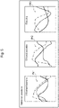
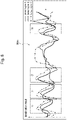
- Fig. 8 is a graph showing an example of time-series data of the fatigue index values of a plurality of construction machines. Specifically, Fig. 8 shows time-series data of the fatigue index values at a specific potion of the booms 14a of the four hydraulic excavators 10 of A to D among the plurality of hydraulic excavators 10.
- the index value calculation unit 115 as the comparison unit compares the degree of fatigue of the hydraulic excavators 10 based on the time-series data of the fatigue index values of the four hydraulic excavators A to D. This comparison shows that the fatigue degree of machine B is the highest and that of machine C is the lowest.
- the movement identification device 100 of the present embodiment clarifies the correlation between a specific motion and a fatigue index value, for example. This makes it possible to create an appropriate work plan according to the fatigue degree of each hydraulic excavator 10 by placing a hydraulic excavator 10 with a high fatigue degree to the work with a low load and placing a hydraulic excavator 10 with a low fatigue degree to the work with a high load, for example.
- the present embodiment provides the movement identification device 100 capable of identifying the type of a motion of a construction machine based on the output of a sensor attached to the construction machine with higher accuracy than the conventional technology.
- the present embodiment provides the movement identification device 100 that uses fatigue index values and so is capable of managing fatigue of each portion of a construction machine more accurately than conventional technology.
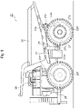
- Fig. 9 is a side view of a dump truck 20 equipped with a movement identification device 100 according to Embodiment 2 of the present disclosure.
- the movement identification device 100 of the present embodiment is different from the movement identification device 100 of Embodiment 1 as described above in that the construction machine to be managed is the dump truck 20. Since the movement identification device 100 of the present embodiment is similar to the movement identification device 100 of Embodiment 1 in other respects, the same numerals indicate like parts, and their descriptions are omitted. The following firstly describes an example of the configuration of the dump truck 20, and then describes the action of the movement identification device 100 of the present embodiment.
- a dump truck 20 shown in Fig. 9 is a large transport vehicle that transports objects to be transported, such as quarried stones from a mine.
- the dump truck 20 has a body frame 21, left and right front wheels 22F, left and right rear wheels 22R, left and right front-wheel side suspensions 23F, left and right rear-wheel side suspensions 23R, a body 24, left and right hoist cylinders 25, a cab 26, a traveling drive system 27, and a housing 28.
- the body frame 21 is a frame-like structure that supports the front wheels 22F, the rear wheels 22R, the front-wheel side suspensions 23F, the rear-wheel side suspensions 23R, the body 24, the hoist cylinders 25, the cab 26, the traveling drive system 27, and the housing 28.
- the left and right front wheels 22F are steering wheels rotatably supported at the front portion of the body frame 21.
- the left and right rear wheels 22R are drive wheels rotatably supported at the rear portion of the body frame 21.
- the left and right front-wheel side suspensions 23F are mounted at the front of the body frame 21 and elastically support the left and right front wheels 22F.
- the left and right rear-wheel side suspensions 23R are mounted at the rear of the body frame 21 and elastically support the left and right rear wheels 22R.
- the upper ends of the left and right rear-wheel side suspensions 23R are attached to the left and right brackets 21b provided to the rear of the body frame 21.
- the lower ends of the left and right rear-wheel side suspensions 23R are attached to an axel housing 27a of the travelling drive system 27.
- the cylinders of the front-wheel side suspensions 23F and the rear-wheel side suspensions 23R of the dump truck 20 each include a hydraulic sensor similar to the hydraulic sensor 18b of the hydraulic excavator 10.
- the hydraulic sensors of the dump truck 20 are force sensors that detect forces acting on the front-wheel side suspensions 23F and the rear-wheel side suspensions 23R.
- the body 24 is a large container that is tiltably mounted on the body frame 21 and has a length of more than 10 meters in the front-rear direction of the dump truck 20, for example.
- the body 24 carries a large amount of mined crushed stone, for example.
- the rear portion of the body 24 at the bottom is connected to the left and right brackets 21b of the body frame 21 via connecting pins 21p, and the front portion at the bottom is connected to the upper end of the hoist cylinders 25.
- the left and right hoist cylinders 25 each have a lower end that is rotatably connected to the body frame 21 and an upper end that is rotatably connected to the body 24.
- the hoist cylinders 8 are hydraulic cylinders. This configuration allows the body 24 to, in response to the expansion of the hoist cylinders 25, rotate around the connecting pins 21p, so as to tilt to the discharge position where the front portion is located above and the rear portion is located below. When the hoist cylinders 25 contracts from this state, the body 24 rotates in the reverse direction around the connecting pins 21p and returns to the loading position shown in Fig. 9 .
- the traveling drive system 27 is connected to the left and right rear wheels 22R and rotationally drives them.
- the traveling drive system 27 has an axle housing 27a and a bracket 27b.
- the axle housing 27a has a cylindrical shape extending to the left and right, accommodating a traveling motor, a speed reducer, and the like, which are not shown in the drawing.
- the bracket 27b projects forward from the axle housing 27a. The front end of the bracket 27b is rotatably attached to a mount 21m of the body frame 21.
- the housing 28 defines a machine room at the front of the body frame 21.
- the housing 28 accommodates an engine, a hydraulic pump, and the like, which are not shown in the drawing.
- the cab 26 is placed on a flat floor located at the top of the housing 28.
- the cab 26 has a box shape, and defines the driver's cabin in which the operator boards. Although not shown, a seat on which the operator sits, a steering wheel, an operation pedal, and the like are installed in the cab 26.
- the dump truck 20 includes a controller similar to the controller 15 for the hydraulic excavator 10 shown in Fig. 2 .
- the controller of the dump truck 20 includes a waveform generation unit 111, a motion identification unit 112, and a waveform storage unit 121.
- the dump truck 20 also includes an attitude sensor for detecting the attitude of the dump truck 20.
- the attitude sensor includes an acceleration sensor.
- the dump truck 20 includes a transmitter 19A and a monitor 19B shown in Fig. 2 .
- Fig. 10 shows one example of the reference waveforms Wr1', Wr2', and Wr3' stored in the waveform storage unit 121 of the movement identification device 100 of Fig. 2 .
- the reference waveform Wr1' of the motion of getting over a step is the reference waveform of the motion in which the front wheels 22F and the rear wheels 22R of the dump truck 20 ride on a step and getting over the step, for example.
- the reference waveform Wr2' of the slewing motion indicated by the circled number 2 in Fig. 10 , is the reference waveform of the motion in which the dump truck 20 turns in response to turning of the front wheels 22F as the steering wheels, for example.
- the reference waveform Wr3' of the braking motion is the reference waveform of the motion in which the dump truck 20 decelerates, for example.
- the motions corresponding to the reference waveforms stored in the waveform storage unit 121 are not particularly limited, and the waveform storage unit 121 can store reference waveforms corresponding to arbitrary motions.
- Fig. 11 shows one example of the identification of specific motions by the motion identification unit 112 of the movement identification device 100 of Fig. 2 .
- the combination of the waveforms of sensor signal A shown by the solid line, the sensor signal B shown by the broken line, and the sensor signal C shown by the dashed-dotted line is the motion waveform Wm' of the dump truck 20.
- the motion waveform Wm' is a combination of at least one force waveform and at least one attitude waveform, corresponding to an arbitrary motion of the dump truck 20.
- the motion identification unit 112 identifies the specific motions included in the motion waveform Wm', i.e., the motions of the circled numbers 1 to 3 shown in Fig. 10 .
- the motion identification unit 112 identifies two times of the step getting over motion indicated by the circled number 1, one time of the slewing motion indicated by the circled number 2, and one time of the braking motion indicated by the circled number 3, from the motion waveform Wm' of the dump truck 20 for a predetermined period.
- the movement identification device 100 of the present embodiment identifies a type of a motion of the dump truck 20 also with higher accuracy than conventional technology.
- the movement identification device 100 of the present embodiment includes the waveform generation unit 111, the motion identification unit 112, and the waveform storage unit 121 as described above.
- the movement identification device 100 is configured so that the waveform generation unit 11 generates a force waveform based on the signal of the hydraulic sensor 18b that detects the hydraulic pressure acting on the front-wheel side suspensions 23F and the rear-wheel side suspensions 23R of the dump truck 20, and an attitude waveform based on the signal of the attitude sensor that detects the attitude of the dump truck 20.
- the motion identification unit 112 stores reference waveforms Wr1', Wr2', and Wr3', which are combinations of force waveforms and attitude waveforms corresponding to specific motions of the dump truck 20.
- the stress calculation unit 113 compares a motion waveform Wm', which is a combination of a force waveform and an attitude waveform corresponding to an arbitrary motion of the dump truck 20, with the reference waveforms Wr1', Wr2', and Wr3' stored in the waveform storage unit 120 to identify a specific motion in the arbitrary motion of the dump truck 20.
- the force waveform based on the signal of the hydraulic sensor 18b included in the motion waveform Wm' of the dump truck 20 will be different from the force waveform included in the reference waveforms Wr1', Wr2', and Wr3'.
- the attitude waveform based on the signal of the acceleration sensor, for example, included in the motion waveform Wm' may be similar to or the same as the attitude waveform included in the reference waveforms Wr1', Wr2', and Wr3'.
- the present embodiment prevents erroneous identification of a specific motion.
- the movement identification device 100 of the present embodiment is capable of identifying a type of a motion of the dump truck 20 based on the outputs of the sensor 18 attached to the dump truck 20 with higher accuracy than conventional technology.
- the movement identification device 100 includes the stress calculation unit 113, the damage degree calculation unit 114, and the index value calculation unit 115. Similarly to the hydraulic excavator 10 as stated above, the movement identification device 100 of the present embodiment enables fatigue management of each portion of the dump truck 20 more accurately than the conventional systems, according to the conditions specific to each dump truck 20, each component of the dump truck 20, and each of a plurality of portions of the components, for example.
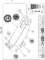
- Fig. 12 shows an example of a monitor image of the movement identification device 100 of the present embodiment.
- Fig. 12 shows an example of the image G displayed on the monitor 19B, associating each of a plurality of portions of the body frame 21 of the dump truck 20 with their corresponding fatigue index values.
- the movement identification device 100 of the present embodiment also provides a visual indication of the fatigue index values for various portions of the components of the dump truck 20.
Abstract
Description
- The present disclosure relates to movement identification devices for construction machines.
- Conventionally inventions about an excavator support device have been known, which assists in detecting incompatibility (mismatching) of a combination for the work content and the work environment and the excavator in operation (see
Patent Literature 1 below). This conventional invention aims to provide an excavator support device capable of accurately determining whether or not an excavator in operation is suitable for the current work content and work environment. - According to one aspect of this conventional invention, an excavator support device includes a display screen that displays an image and a processor that controls the display screen to display an image thereon (see this document,
claim 1, paragraph 0005, for example). The processor acquires the time history of the evaluation value about the cumulative damage degree that is accumulated in the excavator part to be evaluated. The processor compares the evaluation value of cumulative damage degree with a threshold for determination, which increases with operating time. The threshold is for determining whether or not the excavator to be evaluated is in a mismatch condition. If the evaluation value exceeds the threshold, the processor then notifies that the excavator to be evaluated is in a mismatch state. - For this conventional excavator support device, a management device that receives operation information from the excavator can estimate what the excavator is doing, such as ground excavation, excavation at high place, rock excavation, loading, ground leveling, slope leveling, and dismantling, based on the time history of the attachment's attitude (see paragraph 0023 of the document).
- Patent Literature 1:
JP 2016-003462 A - In the conventional excavator support device as described above, the management device estimates the work content of the excavator based on the time history of the attitude of the attachment. Therefore, the management device might erroneously estimate a work content based on the time history of the attachment attitude similar to the work content of the excavator, even when the excavator is not actually performing that work.
- The present disclosure provides a movement identification device capable of identifying a specific motion of a construction machine based on the output of a sensor attached to the construction machine with higher accuracy than the conventional technology.
- An aspect of the present disclosure is a movement identification device that includes: a waveform generation unit configured to generate a force waveform based on a signal of a force sensor that detects a force acting on a construction machine and an attitude waveform based on a signal of an attitude sensor that detects an attitude of the construction machine; a waveform storage unit that stores a reference waveform, which is a combination of the force waveform and the attitude waveform corresponding to a specific motion of the construction machine; and a motion identification unit configured to compare a motion waveform, which is a combination of the force waveform and the attitude waveform corresponding to an arbitrary motion of the construction machine, with the reference waveform to identify the specific motion contained in the arbitrary motion.
- According to the above-described aspect of the present disclosure, it is possible to provide a movement identification device capable of identifying the type of motion of a construction machine based on the output of a sensor attached to the construction machine with higher accuracy than the conventional technology.
-
-
Fig. 1 is a side view of a hydraulic excavator equipped with a movement identification device according toEmbodiment 1 of the present disclosure. -
Fig. 2 is a block diagram of the movement identification device mounted on the hydraulic excavator ofFig. 1 . -
Fig. 3 is a block diagram showing the configuration of a hydraulic drive system of the hydraulic excavator shown inFig. 1 . -
Fig. 4 is a flowchart showing an example of the processing by the movement identification device ofFig. 2 . -
Fig. 5 shows one example of reference waveforms stored in a waveform storage unit of the movement identification device ofFig. 2 . -
Fig. 6 shows one example of the identification of specific motions by the motion identification unit of the movement identification device ofFig. 2 . -
Fig. 7A shows an example of the image displayed on the monitor in the fatigue management system shown inFig. 1 . -
Fig. 7B shows an example of the image displayed on the monitor in the fatigue management system shown inFig. 1 . -
Fig. 7C shows an example of the image displayed on the monitor in the fatigue management system shown inFig. 1 . -
Fig. 8 is a graph showing an example of time-series data of the fatigue index values of a plurality of construction machines. -
Fig. 9 is a side view of a dump truck equipped with a movement identification device according toEmbodiment 2 of the present disclosure. -
Fig. 10 shows one example of reference waveforms stored in a waveform storage unit of the movement identification device ofFig. 2 . -
Fig. 11 shows one example of the identification of specific motions by the motion identification unit of the movement identification device ofFig. 2 . -
Fig. 12 shows an example of the image displayed on the monitor in the fatigue management system shown inFig. 1 . - The following describes an embodiment of a movement identification device according to the present disclosure, with reference to the drawings.
-
Fig. 1 is a side view of a hydraulic excavator equipped with amovement identification device 100 according toEmbodiment 1 of the present disclosure.Fig. 2 is a block diagram of themovement identification device 100 mounted on thehydraulic excavator 10 ofFig. 1 .Fig. 3 is a block diagram showing an example of the configuration of ahydraulic drive system 17 in thehydraulic excavator 10 ofFig. 1 . - As will be described later in detail, the
movement identification device 100 of the present embodiment has the following structure as its main features. Themovement identification device 100 includes awaveform generation unit 111, awaveform storage unit 121, and amotion identification unit 112. Thewaveform generation unit 111 generates a force waveform based on the signal of a force sensor that detects the force acting on the construction machine and an attitude waveform based on the signal of an attitude sensor that detects the attitude of the construction machine. Thewaveform storage unit 121 stores reference waveforms Wr1, Wr2, and Wr3 (seeFig. 5 ), which are combinations of force waveforms and attitude waveforms corresponding to specific motions of the construction machine. Themotion identification unit 112 compares a motion waveform Wm (seeFig. 6 ), which is a combination of a force waveform and an attitude waveform corresponding to an arbitrary motion of a construction machine, with reference waveforms Wr1, Wr2, and Wr3 stored in thewaveform storage unit 121 to identify a specific motion in the arbitrary motion of the construction machine. - The construction machine in which the specific motion is identified by the
movement identification device 100 is not particularly limited. However, the construction machine is ahydraulic excavator 10, for example. For instance, thehydraulic excavator 10 is a supersized hydraulic excavator used in mines. Thehydraulic excavator 10 shown inFig. 1 is a backhoe. However, it is needless to say that the construction machine in which the specific motion is identified by themovement identification device 100 can be a loader. The following firstly describes an example of the configuration of thehydraulic excavator 10 that is one example of the construction machine, and then describes the configuration of each unit of themovement identification device 100 of the present embodiment in details. - In one example, as shown in
Fig. 1 , thehydraulic excavator 10 includes alower traveling body 11, anupper slewing body 12, acab 13, afront working machine 14, and acontroller 15. Thehydraulic excavator 10 also includes asensor 18, atransmitter 19A, and amonitor 19B shown inFig. 2 , and anoperating lever 13a and ahydraulic drive system 17 shown inFig. 3 . The following may describe each part of thehydraulic excavator 10 with reference to a three-dimensional orthogonal coordinate system having X-axis parallel to the front-rear direction of thehydraulic excavator 10, Y axis parallel to the width direction of thehydraulic excavator 10, and Z axis parallel to the height direction of thehydraulic excavator 10. - In one example, the
lower traveling body 11 has atraveling device 11a with a pair of crawlers in the width direction (Y direction) of thehydraulic excavator 10. In one example, thelower traveling body 11 driven by thehydraulic drive system 17 causes traveling of thehydraulic excavator 10. - The
upper slewing body 12 is mounted on the lower travelingbody 11 to be able to swivel. In one example, theupper slewing body 12 is driven by a hydraulic motor or an electric motor, which are not shown, and swivels relative to the lower travelingbody 11 around a rotary shaft parallel to the height direction (Z direction) of thehydraulic excavator 10. In one example, theupper slewing body 12 houses various devices such as an engine (not shown), a hydraulic pump, and a plurality of valves, described later. - In one example, the
cab 13 is a cabin of thehydraulic excavator 10, in which a driver's seat for an operator who manipulates thehydraulic excavator 10 is housed. In one example, thecab 13 is placed above the front portion of theupper slewing body 12 to be adjacent to thefront working machine 14. - In one example, the
front working machine 14 is provided on the front side of theupper slewing body 12 and driven by thehydraulic drive system 17 and performs works such as digging. In one example, thefront working machine 14 has aboom 14a, anarm 14b, and abucket 14c. - In one example, the
boom 14a has a proximal end that connects to theupper slewing body 12 via a rotary shaft parallel to the width direction (Y direction) of thehydraulic excavator 10. In one example, theboom 14a is driven by an actuator and rotates in a predetermined angular range around the rotary shaft mounted to theupper slewing body 12. In one example, ahydraulic cylinder 1 is used as the actuator to drive theboom 14a. Thehydraulic cylinder 1 is a hydraulic actuator driven by hydraulic oil supplied. - In one example, the
hydraulic cylinder 1 has acylinder tube 1a, apiston 1b, and arod 1c. In one example, thehydraulic cylinder 1 is a single-rod hydraulic cylinder having therod 1c protruding to one side of thecylinder tube 1a. Thehydraulic cylinder 1 that drives theboom 14a may be referred to as aboom cylinder 1A, for example. - In the
boom cylinder 1A, one end of thecylinder tube 1a is connected to an intermediate portion of theboom 14a via a rotary shaft parallel to the width direction (Y direction) of thehydraulic excavator 10. Thepiston 1b is housed in thecylinder tube 1a and slides in the axial direction of therod 1c along the inner peripheral face of thecylinder tube 1a. One end of therod 1c is connected to thepiston 1b inside thecylinder tube 1a. In theboom cylinder 1A, the other end of therod 1c extends externally from the inside of thecylinder tube 1A and is connected to theupper slewing body 12 via a rotary shaft parallel to the width direction (Y direction) of thehydraulic excavator 10. - In one example, the
arm 14b has a proximal end that connects to the distal end of theboom 14a via a rotary shaft parallel to the width direction (Y direction) of thehydraulic excavator 10. In one example, thearm 14b is driven by an actuator and rotates in a predetermined angular range around the rotary shaft mounted to theboom 14a. In one example, similarly to theboom cylinder 1A, ahydraulic cylinder 1 is used as the actuator to drive thearm 14b. Thehydraulic cylinder 1 driving thearm 14b may be referred to as anarm cylinder 1B, for example. - In the
arm cylinder 1B, one end of thecylinder tube 1a is connected to an intermediate portion of theboom 14a via a rotary shaft parallel to the width direction (Y direction) of thehydraulic excavator 10. In thearm cylinder 1B, the other end of therod 1c, which is on the other side of the end connecting to thepiston 1b, is connected to the proximal end of thearm 14b via a rotary shaft parallel to the width direction (Y direction) of thehydraulic excavator 10. In one example, therod 1c of thearm cylinder 1B is connected to the proximal end side of thearm 14b more than the distal end of theboom 14a. - In one example, the
bucket 14c has a proximal end that connects to the distal end of thearm 14b via a rotary shaft parallel to the width direction (Y direction) of thehydraulic excavator 10. In one example, thebucket 14c is driven by an actuator and rotates in a predetermined angular range around the rotary shaft mounted to thearm 14b. In one example, ahydraulic cylinder 1 similar to theboom cylinder 1A is used as the actuator to drive thebucket 14c. Thehydraulic cylinder 1 that drives thebucket 14c may be referred to as abucket cylinder 1C, for example. - In the
bucket cylinder 1C, one end of thecylinder tube 1a is connected to the proximal end of thearm 14b, for example, via a rotary shaft parallel to the width direction (Y direction) of thehydraulic excavator 10. In thebucket cylinder 1C, the other end of therod 1c, which is on the other side of the end connecting to thepiston 1b, is connected to the proximal end of thebucket 14c via a link, for example. In one example, the link is connected to therod 1c via a rotary shaft parallel to the width direction (Y direction) of thehydraulic excavator 10. - In one example, the
controller 15 is housed in theupper slewing body 12, and controls thehydraulic drive system 17 based on the pilot pressure in accordance with the operation with the operatinglever 13a in thecab 13 and a signal from thesensor 18 mounted to thehydraulic excavator 10. In one example, thecontroller 15 is a computer unit including acalculation unit 15a such as a central processing unit, amemory 15b such as RAM and ROM, programs stored in thememory 15b, and an input/output unit for inputting/outputting signals. - In one example, the
controller 15 is constituting themovement identification device 100 of the present embodiment. The details of themovement identification device 100 are described later. In one example, themovement identification device 100 may be provided separately from thecontroller 15 that controls thehydraulic drive system 17. In one example, themovement identification device 100 is connected to thesensor 18, thetransmitter 19A, and themonitor 19B via a network such as a control area network (CAN). - In one example, the
hydraulic drive system 17 includes ahydraulic cylinder 1, ahydraulic pump 2, apilot pump 3, a bottom-pressure sensor 4a, an operating-pressure sensor 4b, ahydraulic oil tank 5, and an engine 6. Thehydraulic drive system 17 also includes a directional control valve V1, a variable throttle V2, and a variable throttle control valve V3. In one example, thehydraulic excavator 10 is equipped with three hydraulic cylinders 1: aboom cylinder 1A, anarm cylinder 1B and abucket cylinder 1C. Thesecylinders 1 have a similar configuration. ThereforeFig. 3 shows one of thehydraulic cylinders 1, and omits the other twohydraulic cylinders 1. - As described above, the
hydraulic cylinder 1 has thecylinder tube 1a, thepiston 1b, and therod 1c. The interior of thecylinder tube 1a is divided by thepiston 1b into a bottom-side oil chamber 1e located close to the proximal end of thecylinder tube 1a and a rod-side oil chamber If located close to the distal end of thecylinder tube 1a. - In response to supplying of hydraulic oil into the bottom-
side oil chamber 1e, thepiston 1b of thehydraulic cylinder 1 moves to the distal end of thecylinder tube 1a. Then the hydraulic oil is discharged from the rod-side oil chamber If, so that therod 1c extends. In response to supplying of hydraulic oil into the rod-side oil chamber If, thepiston 1b of thehydraulic cylinder 1 moves to the proximal end of thecylinder tube 1a. Then the hydraulic oil is discharged from the bottom-side oil chamber 1e, so that therod 1c contracts. - Specifically, extension of the
rod 1c of theboom cylinder 1A rotates theboom 14a around the rotary shaft at the proximal end of theboom 14a, and moves the distal end of theboom 14a upward in the height direction (Z direction) of thehydraulic excavator 10. Contraction of therod 1c of theboom cylinder 1A rotates theboom 14a around the rotary shaft at the proximal end of theboom 14a, and moves the distal end of theboom 14a downward in the height direction (Z direction) of thehydraulic excavator 10. - Extension of the
rod 1c of thearm cylinder 1B rotates thearm 14b around the rotary shaft at the proximal end of thearm 14b, and moves the distal end of thearm 14b downward in the height direction (Z direction) of thehydraulic excavator 10. Contraction of therod 1c of thearm cylinder 1B rotates thearm 14b around the rotary shaft at the proximal end of thearm 14b, and moves the distal end of thearm 14b upward in the height direction (Z direction) of thehydraulic excavator 10. - Extension of the
rod 1c of thebucket cylinder 1C rotates thebucket 14c around the rotary shaft at the proximal end of thebucket 14c, and moves the distal end of thebucket 14c upward in the height direction (Z direction) of thehydraulic excavator 10. Contraction of therod 1c of thebucket cylinder 1C rotates thearm 14b around the rotary shaft at the proximal end of thebucket 14c, and moves the distal end of thebucket 14c downward in the height direction (Z direction) of thehydraulic excavator 10. - In one example, the
hydraulic pump 2 is a variable capacity hydraulic pump of the swash plate type, radial piston type or bent axis type. Thehydraulic pump 2 is rotatably driven by the engine 6. In one example, thehydraulic pump 2 has avariable capacity portion 2a including a swash plate, a bent axis, or the like, and avariable volume mechanism 2b that drives thevariable capacity portion 2a. Thevariable volume mechanism 2b drives thevariable capacity portion 2a based on the instruction of thecontroller 15. This changes the tilt angle of thevariable capacity portion 2a to increase or decrease the pump capacity of thehydraulic pump 2. Thehydraulic pump 2 discharges pressure oil into the discharge pipeline. The discharge pipeline branches into a center bypass pipeline and a branch pipeline at a position upstream of the directional control valve VI. - In one example, the
pilot pump 3 is a fixed capacity hydraulic pump. Thepilot pump 3 is also rotatably driven by the engine 6. Thepilot pump 3, together with thehydraulic oil tank 5, constitutes a pilot pressure-oil source. Thepilot pump 3 discharges pilot pressure oil into the pilot pipeline. The pilot pipeline branches into the throttle pilot pipeline for supplying pilot pressure oil to the variable throttle control valve V3 at a position upstream of the operatinglever 13a. - The directional control valve VI switches the pressure oil supplied from the
hydraulic pump 2 to thehydraulic cylinder 1 to control the supply and discharge of the pressure oil at thehydraulic cylinder 1. The directional control valve VI includes a hydraulic pilot type directional control valve with 6 ports and 3 positions. The directional control valve VI is connected to thehydraulic pump 2 via the discharge pipeline, and is connected to thehydraulic oil tank 5 via the center bypass pipeline and the return pipeline. The directional control valve VI is also connected to the bottom-side oil chamber 1e of thehydraulic cylinder 1 via the bottom-side pipeline and to the rod-side oil chamber If of thehydraulic cylinder 1 via the rod-side pipeline. - The variable throttle V2 is located downstream of the directional control valve VI in the middle of the center bypass pipeline. The variable throttle V2 variably throttles the flow area of the center bypass pipeline at a position downstream of the directional control valve VI. The variable throttle V2 is controlled by the pilot pressure oil supplied from the variable throttle control valve V3. The variable throttle V2 has a smaller flow channel area with a larger pilot pressure from the variable throttle control valve V3, and has a larger flow channel area with a smaller pilot pressure. The pilot pressure of the variable throttle control valve V3 is variably controlled by the
controller 15. - The
bottom pressure sensor 4a detects the pressure of the pressure oil in the bottom-side oil chamber 1e of thehydraulic cylinder 1. In one example, thebottom pressure sensor 4a detects the pressure of the bottom-side oil chamber 1e or the bottom-side pipeline. Thebottom pressure sensor 4a is connected to thecontroller 15 via a signal line, and outputs a detection signal corresponding to the detected pressure of the bottom-side oil chamber 1e to thecontroller 15. - The operating
pressure sensor 4b detects the displacement of the operatinglever 13a. In one example, the operatingpressure sensor 4b is placed in the lowering-side pilot pipeline. The operatingpressure sensor 4b detects the hydraulic pressure in the lowering-side pilot pipeline, that is, the pilot pressure for lowering the boom. The operatingpressure sensor 4b is connected to thecontroller 15 via a signal line and detects the pilot pressure of the boom lowering corresponding to the manipulation amount of boom lowering. The operatingpressure sensor 4b outputs a detection signal corresponding to the pilot pressure of the boom lowering to thecontroller 15. - The
sensor 18 is attached to a part of thehydraulic excavator 10, and detects physical quantities and outputs them to thecontroller 15. Specifically, thesensor 18 includes a force sensor that detects a force acting on thehydraulic excavator 10, which is a construction machine, and an attitude sensor that detects the attitude of thehydraulic excavator 10, for example. In the example shown inFig. 2 , thesensor 18 includes ahydraulic sensor 18b as the force sensor, and anangle sensor 18a, anangular rate sensor 18c, anacceleration sensor 18d, aninclination angle sensor 18e, and a not-shown stroke sensor as the attitude sensors. The stroke sensor detects the strokes of theboom cylinder 1A, thearm cylinder 1B, and thebucket cylinder 1C. - In one example, the
hydraulic sensor 18b detects the hydraulic pressure in thehydraulic cylinder 1 of thehydraulic excavator 10, i.e., the pressure of the hydraulic oil in the bottom-side oil chamber 1e. Specifically, thehydraulic sensor 18b detects the pressure of the hydraulic oil in the bottom-side oil chamber 1e of each of theboom cylinder 1A, thearm cylinder 1B, and thebucket cylinder 1C. Thehydraulic sensor 18b may be thebottom pressure sensor 4a described above, for example. When the lower travelingbody 11 and theupper slewing body 12 are driven by a hydraulic motor, thehydraulic sensor 18b detects the pressure of the hydraulic oil of the hydraulic motor. - In one example, the
angle sensor 18a detects the rotating angle of various parts of the construction machine. Specifically, theangle sensor 18a detects the rotating angle of theupper slewing body 12 of thehydraulic excavator 10 and of various parts of the front workingmachine 14, for example. More specifically, thisangle sensor 18a is placed at each of the rotary shaft of theupper slewing body 12, the rotary shaft at the proximal end of theboom 14a, the rotary shaft at the proximal end of thearm 14b, and the rotary shaft at the proximal end of thebucket 14c. In one example, theangle sensor 18a detects the rotation angle of theupper slewing body 12 relative to the lower travelingbody 11, the rotation angle of theboom 14a relative to theupper slewing body 12, the rotation angle of thearm 14b relative to theboom 14a, and the rotation angle of thebucket 14c relative to thearm 14b. - In one example, the
angular rate sensor 18c is attached to each of theupper slewing body 12, theboom 14a, thearm 14b, and thebucket 14c, and detects the angular rates of theupper slewing body 12, theboom 14a, thearm 14b and thebucket 14c. In one example, theacceleration sensor 18d is attached to each of theupper slewing body 12, theboom 14a, thearm 14b, and thebucket 14c, and detects the accelerations of theupper slewing body 12, theboom 14a, thearm 14b and thebucket 14c. In one example, theinclination angle sensor 18e is attached to each of theupper slewing body 12, theboom 14a, thearm 14b, and thebucket 14c, and detects the inclination angles of theupper slewing body 12, theboom 14a, thearm 14b and thebucket 14c. - In one example, the
transmitter 19A is connected to thecontroller 15, and transmits information on the motion of thehydraulic excavator 10 and a fatigue index value output from thecontroller 15 to the outside. Thetransmitter 19A may transmit identification information on thehydraulic excavator 10. Thehydraulic excavator 10 may be equipped with a positioning device such as a global navigation satellite system (GNSS). In this case, thetransmitter 19A may transmit the position information on thehydraulic excavator 10. - In one example, the
monitor 19B is a display device such as a liquid crystal display device or an organic EL display device placed in thecab 13. In one example, themonitor 19B may include an input device, such as a touch panel. In one example, themonitor 19B displays information on the motion of thehydraulic excavator 10 and a fatigue index value output from thecontroller 15. - With this configuration, in response to the operation by the operator with the operating
lever 13a, the directional control valve VI of thehydraulic excavator 10 moves by the pressure oil from thepilot pump 3, and the pressure oil of thehydraulic pump 2 is guided to the bottom-side oil chamber 1e or the rod-side oil chamber If of thehydraulic cylinder 1. As a result, thehydraulic excavator 10 expands or contracts therods 1c of theboom cylinder 1A, thearm cylinder 1B, and thebucket cylinder 1C according to the displacement of the operatinglever 13a as described above to operate each part of theboom 14a, thearm 14b, and thebucket 14c. - The
controller 15 controls the hydraulic motor or the electric motor between the lower travelingbody 11 and theupper slewing body 12 in accordance with the operation signal from the operatinglever 13a. As a result, thehydraulic excavator 10 swivels theupper slewing body 12 relative to the lower travelingbody 11 in accordance with the displacement of the operatinglever 13a. - Next, the following describes the structure of various units of the
movement identification device 100 of the present embodiment in details. In one example, themovement identification device 100 of the present embodiment includes amotion storage unit 122 in addition to thewaveform generation unit 111, themotion identification unit 112, and thewaveform storage unit 121 as stated above. In one example, themovement identification device 100 of the present embodiment also includes astress calculation unit 113, a damagedegree calculation unit 114, and an indexvalue calculation unit 115. In one example, themovement identification device 100 of the present embodiment also includes a calculationexpression storage unit 123, a S-Ncurve storage unit 124, and an indexvalue storage unit 125. - As shown in
Figs. 1 and2 , themovement identification device 100 of the present embodiment may be configured with thecontroller 15 mounted on thehydraulic excavator 10. Thecontroller 15 does not necessarily have to be mounted on the construction machine, and may be provided outside the construction machine. Specifically, thecontroller 15 may include an information terminal that can receive information of thesensor 18 via atransmitter 19A from thehydraulic excavator 10, for example. - As described above, the
waveform generation unit 111 generates a force waveform based on the signal of a force sensor that detects the force acting on the construction machine and an attitude waveform based on the signal of an attitude sensor that detects the attitude of the construction machine. Specifically, thewaveform generation unit 111 generates a force waveform, which is the time-series data of pressure, based on the signal of thehydraulic sensor 18b that detects the pressure acting on the hydraulic oil inside thehydraulic cylinder 1 of thehydraulic excavator 10, for example. Thewaveform generation unit 111 also generates an attitude waveform, which is the time-series data of the rotating angles of various part of thehydraulic excavator 10, based on the signal of theangle sensor 18a that detects the rotating angle of each part, for example. - The
waveform generation unit 111 may generate a force waveform and an attitude waveform based on the signal of a sensor other than theangle sensor 18a and thehydraulic sensor 18b included in thesensor 18. Thewaveform generation unit 111 may also perform appropriate pre-processing on the generated force waveform and attitude waveform, such as noise removal and gain adjustment. -
Fig. 5 shows one example of the reference waveforms Wr1, Wr2, and Wr3 stored in thewaveform storage unit 121. InFig. 5 , the three waveforms with different line types (solid, dashed, and dashed-dotted) are waveform data based on signals from different sensors, including at least one force sensor and at least one attitude sensor.Fig. 5 shows one reference waveform Wr1, Wr2, or Wr3 for each motion of thehydraulic excavator 10. Note that, in reality, the reference waveform of each motion of thehydraulic excavator 10 includes a plurality of reference waveforms corresponding to various joints and various components of thehydraulic excavator 10, for example. - As described above, the
waveform storage unit 121 stores reference waveforms Wr1, Wr2, and Wr3, which are combinations of force waveforms and attitude waveforms corresponding to specific motions of the construction machine. In one example, thewaveform storage unit 121 stores a plurality of reference waveforms Wr1, Wr2, and Wr3 corresponding to a plurality of different specific motions. Specifically, thewaveform storage unit 121 stores the reference waveforms Wr1, Wr2, and Wr3, including the reference waveform Wr1 corresponding to the downward excavation of thehydraulic excavator 10, the reference waveform Wr2 corresponding to the upward excavation, and the reference waveform Wr3 corresponding to the leveling. - The reference waveform Wr1 of the downward excavation, indicated by the circled
number 1 inFig. 5 , is the reference waveform of the motion in which thehydraulic excavator 10 excavates below thecab 13, for example. The reference waveform Wr2 of the upward excavation, indicated by the circlednumber 2 inFig. 5 , is the reference waveform of the motion in which thehydraulic excavator 10 excavates above thecab 13, for example. The reference waveform Wr3 of the leveling, indicated by the circlednumber 3 inFig. 5 , is the reference waveform of the motion in which thehydraulic excavator 10 levels earth and crushed stone to be flat, for example. The motions corresponding to the reference waveforms stored in thewaveform storage unit 121 are not particularly limited, and thewaveform storage unit 121 can store any number of reference waveforms corresponding to arbitrary motions. -
Fig. 6 shows one example of the identification result of specific motions by themotion identification unit 112. InFig. 6 , the combination of the waveforms of sensor signal A shown by the solid line, the sensor signal B shown by the broken line, and the sensor signal C shown by the dashed-dotted line is the motion waveform Wm of thehydraulic excavator 10. The motion waveform Wm is a combination of at least one force waveform and at least one attitude waveform, corresponding to an arbitrary motion of thehydraulic excavator 10. - As described above, the
motion identification unit 112 compares a motion waveform Wm, which is a combination of a force waveform and an attitude waveform corresponding to an arbitrary motion of a construction machine, with reference waveforms Wr1, Wr2, and Wr3 stored in thewaveform storage unit 121 to identify a specific motion in the arbitrary motion. Specifically, themotion identification unit 112 compares the motion waveform Wm corresponding to an arbitrary motion of thehydraulic excavator 10 with the reference waveforms Wr1, Wr2, and Wr3 of the specific motions shown by the circlednumbers 1 to 3 inFig. 5 , to identify a specific motion included in the arbitrary motion. - In one example, the
motion identification unit 112 performs pattern matching of a part of the motion waveform Wm and the reference waveforms Wr1, Wr2, and Wr3 sequentially to identify the specific motions included in the motion waveform Wm, i.e., the motions of the circlednumbers 1 to 3 shown inFig. 5 . In the example shown inFig. 6 , themotion identification unit 112 identifies two times of the downward excavation indicated by the circlednumber 1, one time of the upward excavation indicated by the circlednumber 2, and one time of the leveling indicated by the circlednumber 3, from the motion waveform Wm of thehydraulic excavator 10 for a predetermined period. - In one example, the
motion identification unit 112 outputs specific motions identified from the motion waveform Wm, including downward excavation, upward excavation, and leveling, to themonitor 19B and themotion storage unit 122. In one example, themotion identification unit 112 obtains the operating time of thehydraulic excavator 10 and the number of specific motions identified during that operating time based on the motion waveform Wm, and outputs them to themonitor 19B and themotion storage unit 122. In one example, themotion identification unit 122 obtains the number of the specific motions per unit time based on the motion waveform Wm, and outputs it to themonitor 19B and themotion storage unit 122. - In one example, the
motion storage unit 122 stores specific motions of thehydraulic excavator 10 output from themotion identification unit 112. In one example, themotion storage unit 122 stores the operating time of thehydraulic excavator 10 and the number of specific motions identified during that operating time output from themotion identification unit 112. In one example, themotion storage unit 122 stores the number of specific motions per unit time output from themotion identification unit 112. - The
stress calculation unit 113 calculates stress acting on a plurality of portions of the construction machine based on the outputs of the force sensor that detects a force acting on the construction machine and an attitude sensor that detects the attitude of the construction machine. Specifically, in one example, thestress calculation section 113 calculates the stress acting on a plurality of portions of each of theboom 14a, thearm 14b, and thebucket 14c of thehydraulic excavator 10 based on the outputs of thesensors 18 attached to theboom 14a, thearm 14b, and thebucket 14c. Although not particularly limited, tens to hundreds of portions may be set for each component. - An example of the stress calculation method by the
stress calculation unit 113 is as follows. As shown inFig. 2 , thestress calculation unit 113 calculates the stress acting on a plurality of portions of each component constituting thehydraulic excavator 10 using a stress calculation expression stored in advance in the calculationexpression storage unit 123, for example. The stress calculation expression, for example, represents the relationship between the outputs of thesensor 18 and the stress acting on a plurality of portions of the components of thehydraulic excavator 10. The stress calculation expression is obtained in advance for each portion of the components of thehydraulic excavator 10 using a multiple regression equation or a regression equation using machine learning, and is stored in the calculationexpression storage unit 123. - An example of the stress calculation equations is shown in the following expressions (1) to (3). In expressions (1) to (3), σ1, σ2, ... denote stresses acting on a plurality of portions of the components of the
hydraulic excavator 10. In expressions (1) to (3), s1, s2, ... denote the outputs of thesensors 18, M, N and A are constants based on the characteristics of these portions, and t denotes the time. Thus, the stress calculation equations may be obtained in advance, whereby the stress acting on each of many portions of the components of thehydraulic excavator 10 and the time-history stress waveforms can be easily obtained by simple calculations based on the output of thesensor 18. - [Mathematical 1]

- [Mathematical 2]

- [Mathematical 3]

- The damage
degree calculation unit 114 calculates the cumulative damage degree at each portion based on the stress acting on the portion calculated by thestress calculation unit 113. Specifically, the damagedegree calculation unit 114 calculates the cumulative damage degree D at each portion of the components based on the time-history stress waveform acting on the portion of the components of thehydraulic excavator 10 and the S-N curve of the stress amplitude and the number of repetitions that is stored in advance in the S-Ncurve storage unit 124. In one example, the cumulative damage degree can be calculated by the Miner's law shown in expression (4) below or the modified Miner's law, following the frequency analysis of the time-history stress waveform by the range-pair counting, the peak valley method, or the rainflow counting. - [Mathematical 4]

- The index
value calculation unit 115 calculates a fatigue index value, which is a weighted value of the cumulative damage degree calculated by the damagedegree calculation unit 114, for each portion of the components of thehydraulic excavator 10. In one example, the fatigue index value is obtained by assigning the weighting according to the usage environment, material properties, and other factors for each component and each portion of thehydraulic excavators 10 to the cumulative damage degree calculated for each portion of the components of thehydraulic excavator 10. The fatigue index value indicates the degree of fatigue and is represented by an integer increasing from 1, for example. - An example of the calculation equation for fatigue index value is shown in the following expression (5). In expression (5), i1, i2, ... denote fatigue index values of each portion of the components, a denotes an arbitrary coefficient, and wa1, wa2, ... and wb1, wb2, ... and b1, b2, ... denote numerical values for weighting specific to each portion of the components of the
hydraulic excavator 10. Further, d1, d2, ... denote the cumulative damage degree of each portion of the components. - [Mathematical 5]

- The weightings wa1, wa2, ..., wb1, wb2, ... and b1, b2, ... according to the operating environment, material properties, and other conditions for each
hydraulic excavator 10, each component, and each portion are stored in thememory 15b, together with the calculation expression such as expression (5). In one example, a user or a seller of thehydraulic excavator 10 can freely change these weightings by inputting information to the input device of themonitor 19B or the input device of an information terminal (not shown) according to the individual request or environment. In one example, the indexvalue calculation unit 115 uses the calculation expression as shown in expression (5), for example, to calculate the fatigue index values i1, i2, ... from the cumulative damage degree d1, d2, ... calculated by the damagedegree calculation unit 114. - The
movement identification device 100 of the present embodiment may further include a comparison unit that compares a degree of fatigue based on time series data of the fatigue index value. In one example, the comparison unit may be part of the indexvalue calculation unit 115. In other words, the indexvalue calculation unit 115 may also function as the comparison unit that compares a degree of fatigue based on time series data of the fatigue index value. The indexvalue calculation unit 115 functioning as the comparison unit outputs the comparison result of the degree of fatigue to themonitor 19B and the indexvalue storage unit 125, for example. - Referring to
Figs. 4 to 8 , the following describes the action of themovement identification device 100 of the present embodiment.Fig. 4 is a flowchart showing an example of the processing by themovement identification device 100 ofFig. 2 . - In one example, in response to activation of the
hydraulic excavator 10 by the operator, themovement identification device 100 starts generating a force waveform and an attitude waveform by thewaveform generation unit 111 and calculating the fatigue index value by thestress calculation unit 113. First, thewaveform generation unit 111 and thestress calculation unit 113 perform determination process P1 as to whether or not the data acquired from thesensor 18 includes not-calculated data. Specifically, in the determination process P1, thewaveform generation unit 111 and thestress calculation unit 113 search for the data acquired from thesensor 18. If there is new data that has not been processed in the past (YES), these units perform process P2 to read the data. In the determination process P1, if there is no new data that has not been processed in the past (NO), thewaveform generation unit 111 and thestress calculation unit 113 perform process P3 that waits for a certain period of time, and then return to the determination process P1. - After reading data in the process P2, the
waveform generation unit 111 performs process P4 to read reference waveforms Wr1, Wr2, and Wr3 as shown inFig. 5 from thewaveform storage unit 121. Following the process P2 of reading the data, thestress calculation unit 113 performs the process of selecting one evaluation point that has not undergone calculation from the plurality of evaluation points corresponding to the plurality of portions of the components of thehydraulic excavator 10. For this process, all the evaluation points have individual numbers assigned, and thestress calculation unit 113 selects the not-calculated evaluation points in ascending order one by one starting from the evaluation point with the smallest number. - After the end of the process P4, the
waveform generation unit 111 generates a force waveform and an attitude waveform based on the data read in the process P2, and performs process P5 to generate a motion waveform Wm corresponding to an arbitrary motion of thehydraulic excavator 10. Thestress calculation unit 113 uses the above-described calculation expressions (1) to (3) and the data read at the process P2, for example, to perform process that calculates a time-series stress waveform at the selected evaluation point, that is, a time-history stress waveform. - After that, the
motion identification unit 112 compares the motion waveform Wm generated in the process P5 with the reference waveforms Wr1, Wr2, and Wr3 read in the process P4. Then, as shown inFigs. 5 and6 , themotion identification unit 112 performs process P6 to identify a specific motion of thehydraulic excavator 10 from the motion waveform Wm corresponding to the arbitrary motion of thehydraulic excavator 10. Examples of the specific motion include downward excavation of the circlednumber 1, upward excavation of the circlednumber 2, and leveling of the circlednumber 3. - The damage
degree calculation unit 114 performs the process that calculates the cumulative damage degree at the selected evaluation point based on the time-history stress waveform calculated by thestress calculation unit 113 as described above. The indexvalue calculation unit 115 then performs the process that calculates the fatigue index value of the selected evaluation point using the cumulative damage degree calculated by the damagedegree calculation unit 114 as described above. - After the end of the process P6, in one example, the
motion identification unit 112 performs process P7 that outputs the specific motion identified from the motion waveform Wm to themonitor 19B and themotion storage unit 122. In one example, in process P7, themotion identification unit 112 outputs the specific motion as well as the operating time of thehydraulic excavator 10, the number of the specific motions identified during that operating time, and the number of the specific motions per unit time to themonitor 19B and themotion storage unit 122. In one example, the determination process P1 to the process P7 can be repeated from turning-on of the start switch of thehydraulic excavator 10 to turning-off of the switch. Tables 1 and 2 below show an example of the information displayed on themonitor 19B. When the machine itself is machine A, only the information on machine A is displayed on itsown monitor 19B. When the machine can obtain information on other machines, the monitor can display information of machines A to D as shown below. The information on each machine may be transmitted to an external management device, for example, by thetransmitter 19B, and the operator can confirm the status of a plurality of hydraulic excavators as shown in Tables 1 and 2 below.[Table 1] LIFE INFORMATION MACHINE A MACHINE B MACHINE C MACHINE D OPERATING TIME[HR] 15,890 1,439 8,593 17,582 DOWNWARD EXCAVATION [TIMES] 762,720 30,219 154,674 316,476 UPWARD EXCAVATION [TIMES] 31,780 2,878 42,965 492,296 LEVELING [TIMES] 15,890 0 51,558 228,566 [Table 2] MOTIONS MACHINE A MACHINE B MACHINE C MACHINE D DOWNWARD EXCAVATION [TIMES/HR] 48 21 18 18 UPWARD EXCAVATION [TIMES/HR] 2 2 5 28 LEVELING [TIMES/HR] 1 0 6 13 - In this way, the movement identification device of the present embodiment identifies a specific motion from an arbitrary motion of the
hydraulic excavator 10 to clarify the unbalanced state in motion of eachhydraulic excavator 10. In addition, if the number of specific tasks exceeds a specific number or the number of specific motions per short period of time exceeds a threshold, the device can issue an alarm, for example, to recommend inspection of the machine. - The index
value calculation unit 115 determines whether or not the fatigue index value has been calculated for all the evaluation points. If the result of the determination shows that the calculation of all the evaluation points has not been completed, the indexvalue calculation unit 115 returns to the process that selects one of the not-calculated evaluation points. If the result of the determination shows that the calculation of all the evaluation points is completed, the indexvalue calculation unit 115 determines whether the fatigue index value exceeds a threshold of each evaluation point stored in thememory 15b, for example. - In this determination, the index
value calculation unit 115 may compare the fatigue index value of each of the evaluation points with the threshold of the evaluation point, or may compare the fatigue index value of each of a plurality of evaluation points selected in advance with the threshold of the selected evaluation point. If the result of the determination shows that the fatigue index value exceeds the threshold at any evaluation point, then the indexvalue calculation unit 115 may send an alarm recommending inspection of the portion corresponding to the evaluation point to the information terminal via thetransmitter 19A or may display it on themonitor 19B, for example. - After that, the index
value calculation unit 115 performs the process of outputting the fatigue index values of all the evaluation points to themonitor 19B and thememory 15b, and the procedure returns to the determination process P1. In one example, the determination process P1 to the process of outputting the fatigue index values can be repeated from turning-on of the start switch of thehydraulic excavator 10 to turning-off of the switch. - As described above, the
movement identification device 100 of the present embodiment includes thewaveform generation unit 111, thewaveform storage unit 121, and themotion identification unit 112. Thewaveform generation unit 111 generates a force waveform based on the signal of a force sensor that detects the force acting on the construction machine and an attitude waveform based on the signal of an attitude sensor that detects the attitude of the construction machine. Thewaveform storage unit 121 stores reference waveforms Wr1, Wr2, and Wr3, which are combinations of force waveforms and attitude waveforms corresponding to specific motions of the construction machine. Themotion identification unit 112 compares a motion waveform Wm, which is a combination of a force waveform and an attitude waveform corresponding to an arbitrary motion of a construction machine, with reference waveforms Wr1, Wr2, and Wr3 stored in thewaveform storage unit 121 to identify a specific motion in the arbitrary motion of thehydraulic excavator 10. - This configuration enables identification of the type of a motion of the construction machine based on the output of the
sensor 18 attached to the construction machine with higher accuracy than the conventional technology. Thus, the present embodiment provides themovement identification device 100 capable of identifying a specific motion of thehydraulic excavator 10, such as downward excavation, upward excavation, and leveling, based on the outputs of theangle sensor 18a and thehydraulic sensor 18b of thehydraulic excavator 10 from an arbitrary motion of thehydraulic excavator 10 with higher accuracy than conventional technology. - Specifically, the conventional excavator support device as described above is configured so that the management device estimates the work content of the excavator based on the time history of the attitude of the attachment. Therefore, the management device might erroneously estimate the work content based on the time history of the attachment attitude similar to the work content of the excavator, even when the excavator is not actually performing that work.
- In contrast, the
movement identification device 100 of the present embodiment is configured so that thewaveform generation unit 111 generates a force waveform based on the signal of thehydraulic sensor 18b that detects the hydraulic pressure acting on thehydraulic cylinder 1 of thehydraulic excavator 10 and an attitude waveform based on the signal of theangle sensor 18a that detects the rotation angle of each part of thehydraulic excavator 10. Thewaveform storage unit 121 stores reference waveforms Wr1, Wr2, and Wr3, which are combinations of force waveforms and attitude waveforms corresponding to specific motions of thehydraulic excavator 10. Themotion identification unit 112 compares a motion waveform Wm, which is a combination of a force waveform and an attitude waveform corresponding to an arbitrary motion of thehydraulic excavator 10, with the reference waveforms Wr1, Wr2, and Wr3 stored in thewaveform storage unit 121 to identify a specific motion in the arbitrary motion of thehydraulic excavator 10. - With this configuration, when the
hydraulic excavator 10 is not performing a specific motion, the force waveform based on the signal of thehydraulic sensor 18b included in the motion waveform Wm of thehydraulic excavator 10 will be different from the force waveform included in the reference waveforms Wr1, Wr2, and Wr3. When thehydraulic excavator 10 is not performing a specific motion, the attitude waveform based on the signal of theangle sensor 18a included in the motion waveform Wm may be similar to or the same as the attitude waveform included in the reference waveforms Wr1, Wr2, and Wr3. Even in this case, the present embodiment prevents erroneous identification of a specific motion. Thus, themovement identification device 100 of the present embodiment is capable of identifying a type of a motion of thehydraulic excavator 10 based on the outputs of thesensor 18 attached to thehydraulic excavator 10 with higher accuracy than conventional technology. - The
movement identification device 100 of the present embodiment is configured so that thewaveform storage unit 121 stores a plurality of different reference waveforms Wr1, Wr2, and Wr3 corresponding to a plurality of different specific motions. This configuration allows the movement identification device to identify a plurality of specific motions corresponding to the plurality of reference waveforms Wr1, Wr2, and Wr3 from an arbitrary motion of thehydraulic excavator 10. Simply storing a reference waveform corresponding to a new specific motion in thewaveform storage unit 121 allows the movement identification device to easily identify the new specific motion from an arbitrary motion of thehydraulic excavator 10. - In the
movement identification device 100 of the present embodiment, the force sensor that detects a force acting on the construction machine is thehydraulic sensor 18b that measures the hydraulic pressure in thehydraulic cylinder 1 of the construction machine. With this configuration, thebottom pressure sensor 4a conventionally provided in thehydraulic drive system 17 of thehydraulic excavator 10 can be used as thehydraulic sensor 18b, for example. In this way, the present embodiment does not require the installment of a sensor such as a strain gauge just for measuring the force. Themovement identification device 100 therefore can be easily used for a construction machine, such as thehydraulic excavator 10. Further, the stress acting on each part of thehydraulic excavator 10 can be calculated more accurately based on the output of thehydraulic sensor 18b. - In the
movement identification device 100 of the present embodiment, the attitude sensor that detects the attitude of the construction machine is theangle sensor 18a that detects the rotation angle of each part of the construction machine. Specifically, the attitude sensor that detects the attitude of thehydraulic excavator 10 in themovement identification device 100 of the present embodiment is theangle sensor 18a that detects the relative rotation angles between the lower travelingbody 11 and theupper slewing body 12, theupper slewing body 12 and theboom 14a, theboom 14a and thearm 14b, and thearm 14b and thebucket 14c. - With this configuration, the
angle sensor 18a conventionally provided in thehydraulic excavator 10 can be used as the attitude sensor, for example. Themovement identification device 100 therefore can be easily used for a construction machine, such as thehydraulic excavator 10. Further, the stress acting on each part of thehydraulic excavator 10 can be calculated more accurately based on the output of theangle sensor 18a. - In the
movement identification device 100 of the present embodiment, the attitude sensor that detects the attitude of the construction machine includes theacceleration sensor 18d. This configuration enables measurement of the attitude of the construction machine more correctly and identification of the type of a motion of the construction machine more accurately. - The
movement identification device 100 of the present embodiment includes thestress calculation unit 113, the damagedegree calculation unit 114, and the indexvalue calculation unit 115. Thestress calculation unit 113 calculates stress acting on a plurality of portions of the construction machine based on the outputs of the force sensor and the attitude sensor. The damagedegree calculation unit 114 calculates the cumulative damage degree of each portion of the construction machine based on the stress calculated by thestress calculation unit 113. The indexvalue calculation unit 115 calculates a fatigue index value, which is a weighted value of the cumulative damage degree, for each portion. - This configuration enables the
movement identification device 100 to manage the fatigue of each portion of the construction machine more accurately than the conventional systems, according to the conditions specific to each construction machine, each component of the construction machine, and each of a plurality of portions of the components, for example. - Specifically, the cumulative damage degree directly used in the conventional excavator support device is based on the linear cumulative damage rule, which is an empirical rule, and assumes that the object will undergo fatigue fracture when the cumulative damage degree reaches 1. The cumulative damage degree, however, is a value that inherently includes fluctuations, and in reality, an object may undergo fatigue failure before the cumulative damage degree reaches 1, or the object may not undergo fatigue failure even if the cumulative damage degree exceeds 1. The conventional excavator support device, which uses the cumulative damage degree as it as, may fail to appropriately set the inspection timing for each excavator part.
- In contrast, the
movement identification device 100 of the present embodiment is configured so that the indexvalue calculation unit 115 calculates a fatigue index value, which is a weighted value of the cumulative damage degree, for each portion. This configuration enables the management of fatigue at eachhydraulic excavator 10 and at theupper slewing body 12, theboom 14a, thearm 14b, thebucket 14c, and a plurality of portions of these components of thehydraulic excavator 10 according to their specific conditions. - Specifically, the weightings may be assigned to the cumulative damage degree so that, among the components of the
hydraulic excavator 10, a component having a high risk of damage or a specific portion of such a component has a higher fatigue index value than the fatigue index values of other components or other portions, for example. Therefore, using the fatigue index values calculated by the indexvalue calculation unit 115 enables the fatigue management of the components and specific portions having a high risk of damage more accurately and safely. -
Figs. 7A to 7C show an example of the images G displayed on themonitor 19B of themovement identification device 100 shown inFig. 2 . Themovement identification device 100 of the present embodiment may display the fatigue index values calculated by the indexvalue calculation unit 115 on themonitor 19B. -
Fig. 7A shows an example of the image G displayed on themonitor 19B, associating each of a plurality of portions of thearm 14b of thehydraulic excavator 10 with their corresponding fatigue index values. In this image G, ten arbitrary points from point a to point j are selected from the plurality of portions of thearm 14b. The fatigue index values are indexes and are represented by an integer increasing from 1, for example. In one example, the fatigue index values are displayed as five-level "index" from level Lv.1 to level Lv.5 for each of the portions of points a to j of thearm 14b. In the five levels, level Lv.1 has the smallest fatigue index value, and level Lv.5 has the largest fatigue index value. - In the example shown in
Fig. 7A , the image G shows the image of thearm 14b, lead lines drawn from the portions of points a to j of thearm 14b, and circles having letters inside to indicate the portions that are displayed at the tip ends of the lead lines. In one example, these circles are displayed with a diameter and a color corresponding to the level of the index. Specifically, for instance, the circle has a large diameter for a portion having high index level and fatigue index value, and has a small diameter for a portion having low index level and fatigue index value. For instance, the circle and the cell in the table are colored dark for a portion having high index level and fatigue index value, and are colored light for a portion having low index level and fatigue index value. This provides a visual indication of the fatigue index values for various portions of the components of thehydraulic excavator 10. -
Fig. 7B shows an example of the image G displayed on themonitor 19B, associating each of a plurality of portions of the structure constituting theupper slewing body 12 of thehydraulic excavator 10 with their corresponding fatigue index values.Fig. 7C shows an example of the image G displayed on themonitor 19B, associating each of a plurality of portions of the structure constituting the lower travelingbody 11 of thehydraulic excavator 10 with their corresponding fatigue index values. Similarly to the example ofFig. 7A , these examples also provide a visual indication of the fatigue index values for various portions of the components of thehydraulic excavator 10. - The
movement identification device 100 of the present embodiment enables setting of the weighting of the cumulative damage degree by thestress calculation unit 113 so that the fatigue index value is larger at a site where access is difficult, such as a mine in a remote area, than at a site where access is easy. This makes it possible to request inspections of the construction machine operated at sites where access is difficult at an earlier time than at sites that are easily accessible, thereby enabling highly accurate fatigue management of construction machines according to the site environment. - The
movement identification device 100 of the present embodiment also enables setting of the weighting of the cumulative damage degree by thestress calculation unit 113 so that the fatigue index value is larger for the components of the construction machine that take a longer time to be replaced or repaired or the portions that are more difficult in maintenance than for other components and portions. This enables highly accurate fatigue management of construction machines according to the characteristics of the components of the construction machine and the ease of maintenance of each portion. - In the
movement identification device 100 of the present embodiment, thesensor 18 includes a force sensor that detects a force acting on the construction machine, and an attitude sensor that detects the attitude of the construction machine. Conventionally such force sensor and attitude sensor have been installed in the construction machine for purposes of understanding the operating conditions of the construction machine and avoiding accidents that are different from the purpose of calculating stresses acting on various portions of the construction machine. The present embodiment therefore does not require the installment of a sensor such as a strain gauge in the construction machine just for calculating the stress. - The
movement identification device 100 of the present embodiment includes the indexvalue calculation unit 115 that functions as the comparison unit that compares a degree of fatigue based on time series data of the fatigue index value. With this configuration, the present embodiment enables comparison of the degree of fatigue of a specific portion of a construction machine with the threshold for more accurate management of the degree of fatigue of the specific portion of the construction machine. This also enables a comparison of the degree of fatigue among multiple construction machines. -
Fig. 8 is a graph showing an example of time-series data of the fatigue index values of a plurality of construction machines. Specifically,Fig. 8 shows time-series data of the fatigue index values at a specific potion of thebooms 14a of the fourhydraulic excavators 10 of A to D among the plurality ofhydraulic excavators 10. In the example ofFig. 8 , the indexvalue calculation unit 115 as the comparison unit compares the degree of fatigue of thehydraulic excavators 10 based on the time-series data of the fatigue index values of the four hydraulic excavators A to D. This comparison shows that the fatigue degree of machine B is the highest and that of machine C is the lowest. - The
movement identification device 100 of the present embodiment clarifies the correlation between a specific motion and a fatigue index value, for example. This makes it possible to create an appropriate work plan according to the fatigue degree of eachhydraulic excavator 10 by placing ahydraulic excavator 10 with a high fatigue degree to the work with a low load and placing ahydraulic excavator 10 with a low fatigue degree to the work with a high load, for example. - As described above, the present embodiment provides the
movement identification device 100 capable of identifying the type of a motion of a construction machine based on the output of a sensor attached to the construction machine with higher accuracy than the conventional technology. The present embodiment provides themovement identification device 100 that uses fatigue index values and so is capable of managing fatigue of each portion of a construction machine more accurately than conventional technology. - Next referring to
Fig. 9 to Fig. 12 together withFig. 2 , the following describes a movement identification device according toEmbodiment 2 of the present disclosure.Fig. 9 is a side view of adump truck 20 equipped with amovement identification device 100 according toEmbodiment 2 of the present disclosure. - The
movement identification device 100 of the present embodiment is different from themovement identification device 100 ofEmbodiment 1 as described above in that the construction machine to be managed is thedump truck 20. Since themovement identification device 100 of the present embodiment is similar to themovement identification device 100 ofEmbodiment 1 in other respects, the same numerals indicate like parts, and their descriptions are omitted. The following firstly describes an example of the configuration of thedump truck 20, and then describes the action of themovement identification device 100 of the present embodiment. - In one example, a
dump truck 20 shown inFig. 9 is a large transport vehicle that transports objects to be transported, such as quarried stones from a mine. In one example, thedump truck 20 has abody frame 21, left and rightfront wheels 22F, left and rightrear wheels 22R, left and right front-wheel side suspensions 23F, left and right rear-wheel side suspensions 23R, abody 24, left and right hoistcylinders 25, acab 26, a travelingdrive system 27, and ahousing 28. - In one example, the
body frame 21 is a frame-like structure that supports thefront wheels 22F, therear wheels 22R, the front-wheel side suspensions 23F, the rear-wheel side suspensions 23R, thebody 24, the hoistcylinders 25, thecab 26, the travelingdrive system 27, and thehousing 28. - The left and right
front wheels 22F are steering wheels rotatably supported at the front portion of thebody frame 21. The left and rightrear wheels 22R are drive wheels rotatably supported at the rear portion of thebody frame 21. The left and right front-wheel side suspensions 23F are mounted at the front of thebody frame 21 and elastically support the left and rightfront wheels 22F. - The left and right rear-
wheel side suspensions 23R are mounted at the rear of thebody frame 21 and elastically support the left and rightrear wheels 22R. The upper ends of the left and right rear-wheel side suspensions 23R are attached to the left andright brackets 21b provided to the rear of thebody frame 21. The lower ends of the left and right rear-wheel side suspensions 23R are attached to anaxel housing 27a of the travellingdrive system 27. - The cylinders of the front-
wheel side suspensions 23F and the rear-wheel side suspensions 23R of thedump truck 20 each include a hydraulic sensor similar to thehydraulic sensor 18b of thehydraulic excavator 10. In one example, the hydraulic sensors of thedump truck 20 are force sensors that detect forces acting on the front-wheel side suspensions 23F and the rear-wheel side suspensions 23R. - The
body 24 is a large container that is tiltably mounted on thebody frame 21 and has a length of more than 10 meters in the front-rear direction of thedump truck 20, for example. Thebody 24 carries a large amount of mined crushed stone, for example. In one example, the rear portion of thebody 24 at the bottom is connected to the left andright brackets 21b of thebody frame 21 via connectingpins 21p, and the front portion at the bottom is connected to the upper end of the hoistcylinders 25. - The left and right hoist
cylinders 25 each have a lower end that is rotatably connected to thebody frame 21 and an upper end that is rotatably connected to thebody 24. In one example, the hoist cylinders 8 are hydraulic cylinders. This configuration allows thebody 24 to, in response to the expansion of the hoistcylinders 25, rotate around the connectingpins 21p, so as to tilt to the discharge position where the front portion is located above and the rear portion is located below. When the hoistcylinders 25 contracts from this state, thebody 24 rotates in the reverse direction around the connectingpins 21p and returns to the loading position shown inFig. 9 . - The traveling
drive system 27 is connected to the left and rightrear wheels 22R and rotationally drives them. In one example, the travelingdrive system 27 has anaxle housing 27a and abracket 27b. In one example, theaxle housing 27a has a cylindrical shape extending to the left and right, accommodating a traveling motor, a speed reducer, and the like, which are not shown in the drawing. In one example, thebracket 27b projects forward from theaxle housing 27a. The front end of thebracket 27b is rotatably attached to amount 21m of thebody frame 21. - The
housing 28 defines a machine room at the front of thebody frame 21. Thehousing 28 accommodates an engine, a hydraulic pump, and the like, which are not shown in the drawing. Thecab 26 is placed on a flat floor located at the top of thehousing 28. Thecab 26 has a box shape, and defines the driver's cabin in which the operator boards. Although not shown, a seat on which the operator sits, a steering wheel, an operation pedal, and the like are installed in thecab 26. - In one example, the
dump truck 20 includes a controller similar to thecontroller 15 for thehydraulic excavator 10 shown inFig. 2 . In one example, the controller of thedump truck 20 includes awaveform generation unit 111, amotion identification unit 112, and awaveform storage unit 121. Thedump truck 20 also includes an attitude sensor for detecting the attitude of thedump truck 20. In one example, the attitude sensor includes an acceleration sensor. In one example, thedump truck 20 includes atransmitter 19A and amonitor 19B shown inFig. 2 . -
Fig. 10 shows one example of the reference waveforms Wr1', Wr2', and Wr3' stored in thewaveform storage unit 121 of themovement identification device 100 ofFig. 2 . The reference waveform Wr1' of the motion of getting over a step, indicated by the circlednumber 1 inFig. 10 , is the reference waveform of the motion in which thefront wheels 22F and therear wheels 22R of thedump truck 20 ride on a step and getting over the step, for example. The reference waveform Wr2' of the slewing motion, indicated by the circlednumber 2 inFig. 10 , is the reference waveform of the motion in which thedump truck 20 turns in response to turning of thefront wheels 22F as the steering wheels, for example. The reference waveform Wr3' of the braking motion, indicated by the circlednumber 3 inFig. 10 , is the reference waveform of the motion in which thedump truck 20 decelerates, for example. The motions corresponding to the reference waveforms stored in thewaveform storage unit 121 are not particularly limited, and thewaveform storage unit 121 can store reference waveforms corresponding to arbitrary motions. -
Fig. 11 shows one example of the identification of specific motions by themotion identification unit 112 of themovement identification device 100 ofFig. 2 . InFig. 11 , the combination of the waveforms of sensor signal A shown by the solid line, the sensor signal B shown by the broken line, and the sensor signal C shown by the dashed-dotted line is the motion waveform Wm' of thedump truck 20. The motion waveform Wm' is a combination of at least one force waveform and at least one attitude waveform, corresponding to an arbitrary motion of thedump truck 20. - Similarly to
Embodiment 1, themotion identification unit 112 identifies the specific motions included in the motion waveform Wm', i.e., the motions of the circlednumbers 1 to 3 shown inFig. 10 . In the example shown inFig. 11 , themotion identification unit 112 identifies two times of the step getting over motion indicated by the circlednumber 1, one time of the slewing motion indicated by the circlednumber 2, and one time of the braking motion indicated by the circlednumber 3, from the motion waveform Wm' of thedump truck 20 for a predetermined period. - Next the following describes the action of the
movement identification device 100 of the present embodiment. Similarly to thehydraulic excavator 10 as described above, themovement identification device 100 of the present embodiment identifies a type of a motion of thedump truck 20 also with higher accuracy than conventional technology. - Specifically, the
movement identification device 100 of the present embodiment includes thewaveform generation unit 111, themotion identification unit 112, and thewaveform storage unit 121 as described above. Themovement identification device 100 is configured so that thewaveform generation unit 11 generates a force waveform based on the signal of thehydraulic sensor 18b that detects the hydraulic pressure acting on the front-wheel side suspensions 23F and the rear-wheel side suspensions 23R of thedump truck 20, and an attitude waveform based on the signal of the attitude sensor that detects the attitude of thedump truck 20. Themotion identification unit 112 stores reference waveforms Wr1', Wr2', and Wr3', which are combinations of force waveforms and attitude waveforms corresponding to specific motions of thedump truck 20. Further, thestress calculation unit 113 compares a motion waveform Wm', which is a combination of a force waveform and an attitude waveform corresponding to an arbitrary motion of thedump truck 20, with the reference waveforms Wr1', Wr2', and Wr3' stored in the waveform storage unit 120 to identify a specific motion in the arbitrary motion of thedump truck 20. - With this configuration, when the
dump truck 20 is not performing a specific motion, the force waveform based on the signal of thehydraulic sensor 18b included in the motion waveform Wm' of thedump truck 20 will be different from the force waveform included in the reference waveforms Wr1', Wr2', and Wr3'. When thedump truck 20 is not performing a specific motion, the attitude waveform based on the signal of the acceleration sensor, for example, included in the motion waveform Wm' may be similar to or the same as the attitude waveform included in the reference waveforms Wr1', Wr2', and Wr3'. Even in this case, the present embodiment prevents erroneous identification of a specific motion. Thus, themovement identification device 100 of the present embodiment is capable of identifying a type of a motion of thedump truck 20 based on the outputs of thesensor 18 attached to thedump truck 20 with higher accuracy than conventional technology. - The
movement identification device 100 includes thestress calculation unit 113, the damagedegree calculation unit 114, and the indexvalue calculation unit 115. Similarly to thehydraulic excavator 10 as stated above, themovement identification device 100 of the present embodiment enables fatigue management of each portion of thedump truck 20 more accurately than the conventional systems, according to the conditions specific to eachdump truck 20, each component of thedump truck 20, and each of a plurality of portions of the components, for example. -
Fig. 12 shows an example of a monitor image of themovement identification device 100 of the present embodiment.Fig. 12 shows an example of the image G displayed on themonitor 19B, associating each of a plurality of portions of thebody frame 21 of thedump truck 20 with their corresponding fatigue index values. Similarly to the example ofFigs. 7A to 7C , themovement identification device 100 of the present embodiment also provides a visual indication of the fatigue index values for various portions of the components of thedump truck 20. - That is a detailed description of the embodiments of the movement identification device of the present disclosure, with reference to the drawings. The specific configuration of the present disclosure is not limited to the above-stated embodiments, and the design may be modified variously without departing from the spirits of the present disclosure. The present disclosure also covers such modified embodiments.
-
- 1
- Hydraulic cylinder
- 10
- Hydraulic excavator (construction machine)
- 18a
- Angle sensor (attitude sensor)
- 18b
- Hydraulic sensor (force sensor)
- 18c
- Angular rate sensor (attitude sensor)
- 18d
- Acceleration sensor (attitude sensor)
- 18e
- Inclination angle sensor (attitude sensor)
- 20
- Dump truck (construction machine)
- 100
- Movement identification device
- 111
- Waveform generation unit
- 112
- Motion identification unit
- 113
- Stress calculation unit
- 114
- Damage degree calculation unit
- 115
- Index value calculation unit (comparison unit)
- 121
- Waveform storage unit
- Wm
- Motion waveform
- Wm'
- Motion waveform
- Wr1
- Reference waveform
- Wr1'
- Reference waveform
- Wr2
- Reference waveform
- Wr2'
- Reference waveform
- Wr3
- Reference waveform
- Wr3'
- Reference waveform
Claims (4)
- A movement identification device comprising: a waveform generation unit configured to generate a force waveform based on a signal of a force sensor that detects a force acting on a construction machine and an attitude waveform based on a signal of an attitude sensor that detects an attitude of the construction machine;a waveform storage unit that stores a reference waveform, which is a combination of the force waveform and the attitude waveform corresponding to a specific motion of the construction machine; anda motion identification unit configured to compare a motion waveform, which is a combination of the force waveform and the attitude waveform corresponding to an arbitrary motion of the construction machine, with the reference waveform to identify the specific motion contained in the arbitrary motion.
- The movement identification device according to claim 1, wherein the waveform storage unit stores a plurality of different reference waveforms as the reference waveform corresponding to a plurality of different specific motions as the specific motion.
- The movement identification device according to claim 1, further comprising: a stress calculation unit configured to calculate stress acting on a plurality of portions of the construction machine based on an output of the force sensor and the attitude sensor;a damage degree calculation unit configured to calculate a cumulative damage degree of each of the portions based on the stress; andan index value calculation unit configured to calculate a fatigue index value, which is a weighted value of the cumulative damage degree, for each portion.
- The movement identification device according to claim 3, further comprising a comparison unit configured to compare a degree of fatigue based on time series data of the fatigue index value.
Applications Claiming Priority (1)
| Application Number | Priority Date | Filing Date | Title |
|---|---|---|---|
| PCT/JP2019/038471 WO2021064777A1 (en) | 2019-09-30 | 2019-09-30 | Movement identification device |
Publications (2)
| Publication Number | Publication Date |
|---|---|
| EP4008841A1 true EP4008841A1 (en) | 2022-06-08 |
| EP4008841A4 EP4008841A4 (en) | 2023-05-03 |
Family
ID=75337742
Family Applications (1)
| Application Number | Title | Priority Date | Filing Date |
|---|---|---|---|
| EP19947653.2A Pending EP4008841A4 (en) | 2019-09-30 | 2019-09-30 | Movement identification device |
Country Status (6)
| Country | Link |
|---|---|
| US (1) | US20220396933A1 (en) |
| EP (1) | EP4008841A4 (en) |
| JP (1) | JP7234398B2 (en) |
| CN (1) | CN114174603B (en) |
| AU (1) | AU2019469119B2 (en) |
| WO (1) | WO2021064777A1 (en) |
Families Citing this family (3)
| Publication number | Priority date | Publication date | Assignee | Title |
|---|---|---|---|---|
| JP7206985B2 (en) * | 2019-02-08 | 2023-01-18 | コベルコ建機株式会社 | Damage estimation device and machine learning device |
| JP2024001949A (en) * | 2022-06-23 | 2024-01-11 | 日立建機株式会社 | Mechanical performance diagnosis device, and construction machine diagnosis system |
| JP7377391B1 (en) | 2023-04-28 | 2023-11-09 | 株式会社Earthbrain | Estimation device, estimation method and program |
Family Cites Families (13)
| Publication number | Priority date | Publication date | Assignee | Title |
|---|---|---|---|---|
| JP3533130B2 (en) * | 1999-12-24 | 2004-05-31 | 新キャタピラー三菱株式会社 | Load pressure processing method and apparatus |
| JP4820907B2 (en) | 2004-02-10 | 2011-11-24 | 株式会社小松製作所 | Construction machine work machine control device and construction machine work machine control method |
| CN100584542C (en) * | 2005-06-03 | 2010-01-27 | 株式会社小松制作所 | Work machine |
| JP4049386B2 (en) * | 2006-08-25 | 2008-02-20 | 株式会社小松製作所 | Control device for hydraulic drive machine |
| CN102877500B (en) * | 2012-09-29 | 2014-10-29 | 浙江大学 | Automatic identification method for operating cycle stages of excavator |
| JP6333598B2 (en) | 2014-03-27 | 2018-05-30 | 住友重機械工業株式会社 | Excavator support device and excavator |
| JP6320185B2 (en) | 2014-06-16 | 2018-05-09 | 住友重機械工業株式会社 | Excavator support device |
| JP6291394B2 (en) * | 2014-10-02 | 2018-03-14 | 日立建機株式会社 | Hydraulic drive system for work machines |
| US10246855B2 (en) * | 2016-10-10 | 2019-04-02 | Wacker Neuson Production Americas Llc | Material handling machine with bucket shake control system and method |
| WO2018180555A1 (en) * | 2017-03-31 | 2018-10-04 | 住友重機械工業株式会社 | Shovel |
| JP6942532B2 (en) * | 2017-06-21 | 2021-09-29 | 住友重機械工業株式会社 | Excavator |
| KR102638727B1 (en) * | 2018-03-22 | 2024-02-19 | 스미도모쥬기가이고교 가부시키가이샤 | shovel |
| JP6675809B2 (en) * | 2018-04-25 | 2020-04-08 | 住友重機械工業株式会社 | Excavator support device |
-
2019
- 2019-09-30 US US17/640,047 patent/US20220396933A1/en active Pending
- 2019-09-30 WO PCT/JP2019/038471 patent/WO2021064777A1/en active Search and Examination
- 2019-09-30 JP JP2021550741A patent/JP7234398B2/en active Active
- 2019-09-30 AU AU2019469119A patent/AU2019469119B2/en active Active
- 2019-09-30 CN CN201980098812.5A patent/CN114174603B/en active Active
- 2019-09-30 EP EP19947653.2A patent/EP4008841A4/en active Pending
Also Published As
| Publication number | Publication date |
|---|---|
| EP4008841A4 (en) | 2023-05-03 |
| WO2021064777A1 (en) | 2021-04-08 |
| WO2021064777A9 (en) | 2021-06-10 |
| AU2019469119A1 (en) | 2022-03-24 |
| CN114174603A (en) | 2022-03-11 |
| JPWO2021064777A1 (en) | 2021-04-08 |
| CN114174603B (en) | 2023-06-13 |
| US20220396933A1 (en) | 2022-12-15 |
| JP7234398B2 (en) | 2023-03-07 |
| AU2019469119B2 (en) | 2023-12-21 |
Similar Documents
| Publication | Publication Date | Title |
|---|---|---|
| US11814818B2 (en) | Fatigue management system | |
| EP4008841A1 (en) | Movement identification device | |
| CN107407074B (en) | Display system and engineering machinery | |
| WO2017047826A4 (en) | Display system for work machine and work machine | |
| US10036141B2 (en) | Control system for work vehicle, control method and work vehicle | |
| AU2017378140B2 (en) | System and method for monitoring payload distribution and machine including same | |
| JP6841784B2 (en) | Work machine | |
| CN109511267A (en) | The control method of Work machine and Work machine | |
| JP2019105160A (en) | Display system for work machine, and work machine | |
| JP2024028566A (en) | excavator management system | |
| JP7461879B2 (en) | Construction machine display method and construction machine support device | |
| JP2021014783A (en) | Display system for work machine, and work machine | |
| CN113423897B (en) | Damage estimation device and machine learning device | |
| WO2022209214A1 (en) | Computing device and computation method | |
| KR20240042101A (en) | Systems, methods, and working machines for working machines |
Legal Events
| Date | Code | Title | Description |
|---|---|---|---|
| STAA | Information on the status of an ep patent application or granted ep patent |
Free format text: STATUS: THE INTERNATIONAL PUBLICATION HAS BEEN MADE |
|
| PUAI | Public reference made under article 153(3) epc to a published international application that has entered the european phase |
Free format text: ORIGINAL CODE: 0009012 |
|
| STAA | Information on the status of an ep patent application or granted ep patent |
Free format text: STATUS: REQUEST FOR EXAMINATION WAS MADE |
|
| 17P | Request for examination filed |
Effective date: 20220303 |
|
| AK | Designated contracting states |
Kind code of ref document: A1 Designated state(s): AL AT BE BG CH CY CZ DE DK EE ES FI FR GB GR HR HU IE IS IT LI LT LU LV MC MK MT NL NO PL PT RO RS SE SI SK SM TR |
|
| DAV | Request for validation of the european patent (deleted) | ||
| DAX | Request for extension of the european patent (deleted) | ||
| A4 | Supplementary search report drawn up and despatched |
Effective date: 20230405 |
|
| RIC1 | Information provided on ipc code assigned before grant |
Ipc: E02F 9/22 20060101ALI20230330BHEP Ipc: E02F 3/43 20060101ALI20230330BHEP Ipc: E02F 9/26 20060101ALI20230330BHEP Ipc: B60P 1/04 20060101ALI20230330BHEP Ipc: E02F 9/20 20060101AFI20230330BHEP |