EP4008803A1 - Method of and apparatus for oxidative post-processing of a nitrided or nitrocarburized article - Google Patents
Method of and apparatus for oxidative post-processing of a nitrided or nitrocarburized article Download PDFInfo
- Publication number
- EP4008803A1 EP4008803A1 EP21020605.8A EP21020605A EP4008803A1 EP 4008803 A1 EP4008803 A1 EP 4008803A1 EP 21020605 A EP21020605 A EP 21020605A EP 4008803 A1 EP4008803 A1 EP 4008803A1
- Authority
- EP
- European Patent Office
- Prior art keywords
- furnace
- fluid mixture
- water
- article
- nitrocarburized
- Prior art date
- Legal status (The legal status is an assumption and is not a legal conclusion. Google has not performed a legal analysis and makes no representation as to the accuracy of the status listed.)
- Pending
Links
- 238000000034 method Methods 0.000 title claims abstract description 37
- 230000001590 oxidative effect Effects 0.000 title claims abstract description 13
- 238000012805 post-processing Methods 0.000 title claims abstract description 6
- XLYOFNOQVPJJNP-UHFFFAOYSA-N water Substances O XLYOFNOQVPJJNP-UHFFFAOYSA-N 0.000 claims abstract description 58
- 239000000203 mixture Substances 0.000 claims abstract description 49
- 239000012530 fluid Substances 0.000 claims abstract description 37
- CURLTUGMZLYLDI-UHFFFAOYSA-N Carbon dioxide Chemical compound O=C=O CURLTUGMZLYLDI-UHFFFAOYSA-N 0.000 claims abstract description 26
- IJGRMHOSHXDMSA-UHFFFAOYSA-N Atomic nitrogen Chemical compound N#N IJGRMHOSHXDMSA-UHFFFAOYSA-N 0.000 claims abstract description 23
- 229910002092 carbon dioxide Inorganic materials 0.000 claims abstract description 13
- 239000001569 carbon dioxide Substances 0.000 claims abstract description 13
- 238000010438 heat treatment Methods 0.000 claims abstract description 13
- 229910052757 nitrogen Inorganic materials 0.000 claims abstract description 11
- 239000007789 gas Substances 0.000 claims description 30
- 239000007788 liquid Substances 0.000 claims description 3
- XEEYBQQBJWHFJM-UHFFFAOYSA-N Iron Chemical compound [Fe] XEEYBQQBJWHFJM-UHFFFAOYSA-N 0.000 description 4
- 238000010586 diagram Methods 0.000 description 4
- 230000001105 regulatory effect Effects 0.000 description 4
- 229910000831 Steel Inorganic materials 0.000 description 3
- 230000000694 effects Effects 0.000 description 3
- 238000005259 measurement Methods 0.000 description 3
- 239000007800 oxidant agent Substances 0.000 description 3
- 239000010959 steel Substances 0.000 description 3
- 230000001276 controlling effect Effects 0.000 description 2
- 238000001816 cooling Methods 0.000 description 2
- 238000005260 corrosion Methods 0.000 description 2
- 230000007797 corrosion Effects 0.000 description 2
- 230000001419 dependent effect Effects 0.000 description 2
- 229910052742 iron Inorganic materials 0.000 description 2
- 239000000463 material Substances 0.000 description 2
- 229910052751 metal Inorganic materials 0.000 description 2
- 239000002184 metal Substances 0.000 description 2
- 238000005121 nitriding Methods 0.000 description 2
- 230000003647 oxidation Effects 0.000 description 2
- 238000007254 oxidation reaction Methods 0.000 description 2
- RTAQQCXQSZGOHL-UHFFFAOYSA-N Titanium Chemical compound [Ti] RTAQQCXQSZGOHL-UHFFFAOYSA-N 0.000 description 1
- 239000011449 brick Substances 0.000 description 1
- -1 bundle or similar Substances 0.000 description 1
- 239000000919 ceramic Substances 0.000 description 1
- 230000003750 conditioning effect Effects 0.000 description 1
- 238000004320 controlled atmosphere Methods 0.000 description 1
- 238000013461 design Methods 0.000 description 1
- 238000007865 diluting Methods 0.000 description 1
- 239000006185 dispersion Substances 0.000 description 1
- 238000001035 drying Methods 0.000 description 1
- 230000007613 environmental effect Effects 0.000 description 1
- 239000000835 fiber Substances 0.000 description 1
- 239000012467 final product Substances 0.000 description 1
- 238000012423 maintenance Methods 0.000 description 1
- 238000004519 manufacturing process Methods 0.000 description 1
- 239000003595 mist Substances 0.000 description 1
- 150000004767 nitrides Chemical class 0.000 description 1
- JCXJVPUVTGWSNB-UHFFFAOYSA-N nitrogen dioxide Inorganic materials O=[N]=O JCXJVPUVTGWSNB-UHFFFAOYSA-N 0.000 description 1
- 229920000642 polymer Polymers 0.000 description 1
- 238000002360 preparation method Methods 0.000 description 1
- 238000012545 processing Methods 0.000 description 1
- 238000010791 quenching Methods 0.000 description 1
- 230000000171 quenching effect Effects 0.000 description 1
- 238000002310 reflectometry Methods 0.000 description 1
- 238000000926 separation method Methods 0.000 description 1
- 229910001220 stainless steel Inorganic materials 0.000 description 1
- 239000010935 stainless steel Substances 0.000 description 1
- 238000003860 storage Methods 0.000 description 1
- 239000010409 thin film Substances 0.000 description 1
- 239000010936 titanium Substances 0.000 description 1
- 229910052719 titanium Inorganic materials 0.000 description 1
- 238000011144 upstream manufacturing Methods 0.000 description 1
- 239000006200 vaporizer Substances 0.000 description 1
- 230000000007 visual effect Effects 0.000 description 1
Images

Classifications
-
- F—MECHANICAL ENGINEERING; LIGHTING; HEATING; WEAPONS; BLASTING
- F27—FURNACES; KILNS; OVENS; RETORTS
- F27B—FURNACES, KILNS, OVENS OR RETORTS IN GENERAL; OPEN SINTERING OR LIKE APPARATUS
- F27B7/00—Rotary-drum furnaces, i.e. horizontal or slightly inclined
- F27B7/14—Rotary-drum furnaces, i.e. horizontal or slightly inclined with means for agitating or moving the charge
- F27B7/16—Rotary-drum furnaces, i.e. horizontal or slightly inclined with means for agitating or moving the charge the means being fixed relatively to the drum, e.g. composite means
-
- C—CHEMISTRY; METALLURGY
- C23—COATING METALLIC MATERIAL; COATING MATERIAL WITH METALLIC MATERIAL; CHEMICAL SURFACE TREATMENT; DIFFUSION TREATMENT OF METALLIC MATERIAL; COATING BY VACUUM EVAPORATION, BY SPUTTERING, BY ION IMPLANTATION OR BY CHEMICAL VAPOUR DEPOSITION, IN GENERAL; INHIBITING CORROSION OF METALLIC MATERIAL OR INCRUSTATION IN GENERAL
- C23C—COATING METALLIC MATERIAL; COATING MATERIAL WITH METALLIC MATERIAL; SURFACE TREATMENT OF METALLIC MATERIAL BY DIFFUSION INTO THE SURFACE, BY CHEMICAL CONVERSION OR SUBSTITUTION; COATING BY VACUUM EVAPORATION, BY SPUTTERING, BY ION IMPLANTATION OR BY CHEMICAL VAPOUR DEPOSITION, IN GENERAL
- C23C8/00—Solid state diffusion of only non-metal elements into metallic material surfaces; Chemical surface treatment of metallic material by reaction of the surface with a reactive gas, leaving reaction products of surface material in the coating, e.g. conversion coatings, passivation of metals
- C23C8/02—Pretreatment of the material to be coated
-
- C—CHEMISTRY; METALLURGY
- C23—COATING METALLIC MATERIAL; COATING MATERIAL WITH METALLIC MATERIAL; CHEMICAL SURFACE TREATMENT; DIFFUSION TREATMENT OF METALLIC MATERIAL; COATING BY VACUUM EVAPORATION, BY SPUTTERING, BY ION IMPLANTATION OR BY CHEMICAL VAPOUR DEPOSITION, IN GENERAL; INHIBITING CORROSION OF METALLIC MATERIAL OR INCRUSTATION IN GENERAL
- C23C—COATING METALLIC MATERIAL; COATING MATERIAL WITH METALLIC MATERIAL; SURFACE TREATMENT OF METALLIC MATERIAL BY DIFFUSION INTO THE SURFACE, BY CHEMICAL CONVERSION OR SUBSTITUTION; COATING BY VACUUM EVAPORATION, BY SPUTTERING, BY ION IMPLANTATION OR BY CHEMICAL VAPOUR DEPOSITION, IN GENERAL
- C23C8/00—Solid state diffusion of only non-metal elements into metallic material surfaces; Chemical surface treatment of metallic material by reaction of the surface with a reactive gas, leaving reaction products of surface material in the coating, e.g. conversion coatings, passivation of metals
- C23C8/06—Solid state diffusion of only non-metal elements into metallic material surfaces; Chemical surface treatment of metallic material by reaction of the surface with a reactive gas, leaving reaction products of surface material in the coating, e.g. conversion coatings, passivation of metals using gases
- C23C8/08—Solid state diffusion of only non-metal elements into metallic material surfaces; Chemical surface treatment of metallic material by reaction of the surface with a reactive gas, leaving reaction products of surface material in the coating, e.g. conversion coatings, passivation of metals using gases only one element being applied
- C23C8/10—Oxidising
-
- C—CHEMISTRY; METALLURGY
- C23—COATING METALLIC MATERIAL; COATING MATERIAL WITH METALLIC MATERIAL; CHEMICAL SURFACE TREATMENT; DIFFUSION TREATMENT OF METALLIC MATERIAL; COATING BY VACUUM EVAPORATION, BY SPUTTERING, BY ION IMPLANTATION OR BY CHEMICAL VAPOUR DEPOSITION, IN GENERAL; INHIBITING CORROSION OF METALLIC MATERIAL OR INCRUSTATION IN GENERAL
- C23C—COATING METALLIC MATERIAL; COATING MATERIAL WITH METALLIC MATERIAL; SURFACE TREATMENT OF METALLIC MATERIAL BY DIFFUSION INTO THE SURFACE, BY CHEMICAL CONVERSION OR SUBSTITUTION; COATING BY VACUUM EVAPORATION, BY SPUTTERING, BY ION IMPLANTATION OR BY CHEMICAL VAPOUR DEPOSITION, IN GENERAL
- C23C8/00—Solid state diffusion of only non-metal elements into metallic material surfaces; Chemical surface treatment of metallic material by reaction of the surface with a reactive gas, leaving reaction products of surface material in the coating, e.g. conversion coatings, passivation of metals
- C23C8/06—Solid state diffusion of only non-metal elements into metallic material surfaces; Chemical surface treatment of metallic material by reaction of the surface with a reactive gas, leaving reaction products of surface material in the coating, e.g. conversion coatings, passivation of metals using gases
- C23C8/08—Solid state diffusion of only non-metal elements into metallic material surfaces; Chemical surface treatment of metallic material by reaction of the surface with a reactive gas, leaving reaction products of surface material in the coating, e.g. conversion coatings, passivation of metals using gases only one element being applied
- C23C8/10—Oxidising
- C23C8/16—Oxidising using oxygen-containing compounds, e.g. water, carbon dioxide
-
- C—CHEMISTRY; METALLURGY
- C23—COATING METALLIC MATERIAL; COATING MATERIAL WITH METALLIC MATERIAL; CHEMICAL SURFACE TREATMENT; DIFFUSION TREATMENT OF METALLIC MATERIAL; COATING BY VACUUM EVAPORATION, BY SPUTTERING, BY ION IMPLANTATION OR BY CHEMICAL VAPOUR DEPOSITION, IN GENERAL; INHIBITING CORROSION OF METALLIC MATERIAL OR INCRUSTATION IN GENERAL
- C23C—COATING METALLIC MATERIAL; COATING MATERIAL WITH METALLIC MATERIAL; SURFACE TREATMENT OF METALLIC MATERIAL BY DIFFUSION INTO THE SURFACE, BY CHEMICAL CONVERSION OR SUBSTITUTION; COATING BY VACUUM EVAPORATION, BY SPUTTERING, BY ION IMPLANTATION OR BY CHEMICAL VAPOUR DEPOSITION, IN GENERAL
- C23C8/00—Solid state diffusion of only non-metal elements into metallic material surfaces; Chemical surface treatment of metallic material by reaction of the surface with a reactive gas, leaving reaction products of surface material in the coating, e.g. conversion coatings, passivation of metals
- C23C8/06—Solid state diffusion of only non-metal elements into metallic material surfaces; Chemical surface treatment of metallic material by reaction of the surface with a reactive gas, leaving reaction products of surface material in the coating, e.g. conversion coatings, passivation of metals using gases
- C23C8/08—Solid state diffusion of only non-metal elements into metallic material surfaces; Chemical surface treatment of metallic material by reaction of the surface with a reactive gas, leaving reaction products of surface material in the coating, e.g. conversion coatings, passivation of metals using gases only one element being applied
- C23C8/10—Oxidising
- C23C8/16—Oxidising using oxygen-containing compounds, e.g. water, carbon dioxide
- C23C8/18—Oxidising of ferrous surfaces
-
- C—CHEMISTRY; METALLURGY
- C23—COATING METALLIC MATERIAL; COATING MATERIAL WITH METALLIC MATERIAL; CHEMICAL SURFACE TREATMENT; DIFFUSION TREATMENT OF METALLIC MATERIAL; COATING BY VACUUM EVAPORATION, BY SPUTTERING, BY ION IMPLANTATION OR BY CHEMICAL VAPOUR DEPOSITION, IN GENERAL; INHIBITING CORROSION OF METALLIC MATERIAL OR INCRUSTATION IN GENERAL
- C23C—COATING METALLIC MATERIAL; COATING MATERIAL WITH METALLIC MATERIAL; SURFACE TREATMENT OF METALLIC MATERIAL BY DIFFUSION INTO THE SURFACE, BY CHEMICAL CONVERSION OR SUBSTITUTION; COATING BY VACUUM EVAPORATION, BY SPUTTERING, BY ION IMPLANTATION OR BY CHEMICAL VAPOUR DEPOSITION, IN GENERAL
- C23C8/00—Solid state diffusion of only non-metal elements into metallic material surfaces; Chemical surface treatment of metallic material by reaction of the surface with a reactive gas, leaving reaction products of surface material in the coating, e.g. conversion coatings, passivation of metals
- C23C8/06—Solid state diffusion of only non-metal elements into metallic material surfaces; Chemical surface treatment of metallic material by reaction of the surface with a reactive gas, leaving reaction products of surface material in the coating, e.g. conversion coatings, passivation of metals using gases
- C23C8/08—Solid state diffusion of only non-metal elements into metallic material surfaces; Chemical surface treatment of metallic material by reaction of the surface with a reactive gas, leaving reaction products of surface material in the coating, e.g. conversion coatings, passivation of metals using gases only one element being applied
- C23C8/24—Nitriding
-
- C—CHEMISTRY; METALLURGY
- C23—COATING METALLIC MATERIAL; COATING MATERIAL WITH METALLIC MATERIAL; CHEMICAL SURFACE TREATMENT; DIFFUSION TREATMENT OF METALLIC MATERIAL; COATING BY VACUUM EVAPORATION, BY SPUTTERING, BY ION IMPLANTATION OR BY CHEMICAL VAPOUR DEPOSITION, IN GENERAL; INHIBITING CORROSION OF METALLIC MATERIAL OR INCRUSTATION IN GENERAL
- C23C—COATING METALLIC MATERIAL; COATING MATERIAL WITH METALLIC MATERIAL; SURFACE TREATMENT OF METALLIC MATERIAL BY DIFFUSION INTO THE SURFACE, BY CHEMICAL CONVERSION OR SUBSTITUTION; COATING BY VACUUM EVAPORATION, BY SPUTTERING, BY ION IMPLANTATION OR BY CHEMICAL VAPOUR DEPOSITION, IN GENERAL
- C23C8/00—Solid state diffusion of only non-metal elements into metallic material surfaces; Chemical surface treatment of metallic material by reaction of the surface with a reactive gas, leaving reaction products of surface material in the coating, e.g. conversion coatings, passivation of metals
- C23C8/06—Solid state diffusion of only non-metal elements into metallic material surfaces; Chemical surface treatment of metallic material by reaction of the surface with a reactive gas, leaving reaction products of surface material in the coating, e.g. conversion coatings, passivation of metals using gases
- C23C8/08—Solid state diffusion of only non-metal elements into metallic material surfaces; Chemical surface treatment of metallic material by reaction of the surface with a reactive gas, leaving reaction products of surface material in the coating, e.g. conversion coatings, passivation of metals using gases only one element being applied
- C23C8/24—Nitriding
- C23C8/26—Nitriding of ferrous surfaces
-
- C—CHEMISTRY; METALLURGY
- C23—COATING METALLIC MATERIAL; COATING MATERIAL WITH METALLIC MATERIAL; CHEMICAL SURFACE TREATMENT; DIFFUSION TREATMENT OF METALLIC MATERIAL; COATING BY VACUUM EVAPORATION, BY SPUTTERING, BY ION IMPLANTATION OR BY CHEMICAL VAPOUR DEPOSITION, IN GENERAL; INHIBITING CORROSION OF METALLIC MATERIAL OR INCRUSTATION IN GENERAL
- C23C—COATING METALLIC MATERIAL; COATING MATERIAL WITH METALLIC MATERIAL; SURFACE TREATMENT OF METALLIC MATERIAL BY DIFFUSION INTO THE SURFACE, BY CHEMICAL CONVERSION OR SUBSTITUTION; COATING BY VACUUM EVAPORATION, BY SPUTTERING, BY ION IMPLANTATION OR BY CHEMICAL VAPOUR DEPOSITION, IN GENERAL
- C23C8/00—Solid state diffusion of only non-metal elements into metallic material surfaces; Chemical surface treatment of metallic material by reaction of the surface with a reactive gas, leaving reaction products of surface material in the coating, e.g. conversion coatings, passivation of metals
- C23C8/06—Solid state diffusion of only non-metal elements into metallic material surfaces; Chemical surface treatment of metallic material by reaction of the surface with a reactive gas, leaving reaction products of surface material in the coating, e.g. conversion coatings, passivation of metals using gases
- C23C8/28—Solid state diffusion of only non-metal elements into metallic material surfaces; Chemical surface treatment of metallic material by reaction of the surface with a reactive gas, leaving reaction products of surface material in the coating, e.g. conversion coatings, passivation of metals using gases more than one element being applied in one step
- C23C8/30—Carbo-nitriding
-
- C—CHEMISTRY; METALLURGY
- C23—COATING METALLIC MATERIAL; COATING MATERIAL WITH METALLIC MATERIAL; CHEMICAL SURFACE TREATMENT; DIFFUSION TREATMENT OF METALLIC MATERIAL; COATING BY VACUUM EVAPORATION, BY SPUTTERING, BY ION IMPLANTATION OR BY CHEMICAL VAPOUR DEPOSITION, IN GENERAL; INHIBITING CORROSION OF METALLIC MATERIAL OR INCRUSTATION IN GENERAL
- C23C—COATING METALLIC MATERIAL; COATING MATERIAL WITH METALLIC MATERIAL; SURFACE TREATMENT OF METALLIC MATERIAL BY DIFFUSION INTO THE SURFACE, BY CHEMICAL CONVERSION OR SUBSTITUTION; COATING BY VACUUM EVAPORATION, BY SPUTTERING, BY ION IMPLANTATION OR BY CHEMICAL VAPOUR DEPOSITION, IN GENERAL
- C23C8/00—Solid state diffusion of only non-metal elements into metallic material surfaces; Chemical surface treatment of metallic material by reaction of the surface with a reactive gas, leaving reaction products of surface material in the coating, e.g. conversion coatings, passivation of metals
- C23C8/06—Solid state diffusion of only non-metal elements into metallic material surfaces; Chemical surface treatment of metallic material by reaction of the surface with a reactive gas, leaving reaction products of surface material in the coating, e.g. conversion coatings, passivation of metals using gases
- C23C8/28—Solid state diffusion of only non-metal elements into metallic material surfaces; Chemical surface treatment of metallic material by reaction of the surface with a reactive gas, leaving reaction products of surface material in the coating, e.g. conversion coatings, passivation of metals using gases more than one element being applied in one step
- C23C8/30—Carbo-nitriding
- C23C8/32—Carbo-nitriding of ferrous surfaces
-
- C—CHEMISTRY; METALLURGY
- C23—COATING METALLIC MATERIAL; COATING MATERIAL WITH METALLIC MATERIAL; CHEMICAL SURFACE TREATMENT; DIFFUSION TREATMENT OF METALLIC MATERIAL; COATING BY VACUUM EVAPORATION, BY SPUTTERING, BY ION IMPLANTATION OR BY CHEMICAL VAPOUR DEPOSITION, IN GENERAL; INHIBITING CORROSION OF METALLIC MATERIAL OR INCRUSTATION IN GENERAL
- C23C—COATING METALLIC MATERIAL; COATING MATERIAL WITH METALLIC MATERIAL; SURFACE TREATMENT OF METALLIC MATERIAL BY DIFFUSION INTO THE SURFACE, BY CHEMICAL CONVERSION OR SUBSTITUTION; COATING BY VACUUM EVAPORATION, BY SPUTTERING, BY ION IMPLANTATION OR BY CHEMICAL VAPOUR DEPOSITION, IN GENERAL
- C23C8/00—Solid state diffusion of only non-metal elements into metallic material surfaces; Chemical surface treatment of metallic material by reaction of the surface with a reactive gas, leaving reaction products of surface material in the coating, e.g. conversion coatings, passivation of metals
- C23C8/80—After-treatment
-
- F—MECHANICAL ENGINEERING; LIGHTING; HEATING; WEAPONS; BLASTING
- F27—FURNACES; KILNS; OVENS; RETORTS
- F27B—FURNACES, KILNS, OVENS OR RETORTS IN GENERAL; OPEN SINTERING OR LIKE APPARATUS
- F27B5/00—Muffle furnaces; Retort furnaces; Other furnaces in which the charge is held completely isolated
- F27B5/06—Details, accessories or equipment specially adapted for furnaces of these types
- F27B5/16—Arrangements of air or gas supply devices
-
- F—MECHANICAL ENGINEERING; LIGHTING; HEATING; WEAPONS; BLASTING
- F27—FURNACES; KILNS; OVENS; RETORTS
- F27D—DETAILS OR ACCESSORIES OF FURNACES, KILNS, OVENS OR RETORTS, IN SO FAR AS THEY ARE OF KINDS OCCURRING IN MORE THAN ONE KIND OF FURNACE
- F27D7/00—Forming, maintaining or circulating atmospheres in heating chambers
- F27D7/02—Supplying steam, vapour, gases or liquids
-
- F—MECHANICAL ENGINEERING; LIGHTING; HEATING; WEAPONS; BLASTING
- F27—FURNACES; KILNS; OVENS; RETORTS
- F27D—DETAILS OR ACCESSORIES OF FURNACES, KILNS, OVENS OR RETORTS, IN SO FAR AS THEY ARE OF KINDS OCCURRING IN MORE THAN ONE KIND OF FURNACE
- F27D7/00—Forming, maintaining or circulating atmospheres in heating chambers
- F27D7/06—Forming or maintaining special atmospheres or vacuum within heating chambers
Definitions
- the present invention relates to a method of oxidative post-processing of a nitrided or nitrocarburized article (or workpiece or another object) and to an apparatus for carrying out such a method
- Nitrocarburizing and nitriding of steel or other iron based metal objects produces a hard and smooth surface on the treated objects.
- Post-treatment oxidation of the surface can further enhance corrosion resistance and the visual appearance of the object's surface.
- the present invention proposes a method of oxidative post-processing of a nitrided or nitrocarburized article and an apparatus for carrying out the same with the features of the independent claims.
- Advantageous embodiments are subject-matter of the dependent claims and the description herein below.
- the invention makes use of water vapor as an oxidant and uses otherwise gases which are generally present at heat treatment facilities as further oxidizing agents and/or dilutants for the water vapor.
- the oxidative post-treatment can be carried out in a controlled manner with high precision with less expected furnace wear and maintenance resulting in improved furnace lifetime.
- a method according to the invention comprises providing the article in a furnace, preparing a fluid mixture containing at least water and one or more of carbon dioxide and nitrogen, controlling the water content of the fluid mixture, providing the fluid mixture to the furnace, and heating the furnace, preferably to a temperature level in the range of 400 °C to 600 °C. Under these process conditions, water vapor as well as carbon dioxide serve as oxidizing agents with respect to the nitrided or nitrocarburized surface, respectively.
- the diluting effect of the admixed gas minimizes the negative effects a moist furnace could have on subsequent processes and abolishes or at least reduces the need for drying steps between subsequent processes.
- nitrocaburizing and nitriding are processes used to harden iron based metal objects.
- Typical examples of objects or articles, to which such processes are applied include, without limitation, gun or rifle barrels and slides, bearings, drills, spindles, gears, dies, hydraulic pistons and other parts which during use generally come into dynamic contact with other similarly hard surfaces and are therefore prone to friction induced wear.
- US 2007/0251605 A1 proposes a process for producing highly corrosion-resistant articles made of steel by subjecting the surface of a nitride steel article to an oxidizing heat treatment.
- the heat treatment atmosphere contains for example air and steam at a volume ratio of 50:50.
- such an oxidizing process is hard to control since the air has an undefined water content.
- the invention proposes to control the water content and in particular the dew point of the fluid mixture before it is introduced into the furnace.
- the dew point depends on the moisture content of the gases which are blended to produce the fluid mixture and it is independent of the temperature contrary to the relative humidity which is temperature dependent.
- the fluid mixture is prepared such that a dew point of the mixture under a pressure in the range of 1 - 50 Pa gauge (above atmospheric pressure) that is present in the furnace during heating is in the range of 0 °C to 50 °C, preferably in the range of 10 °C to 30 °C. Under such conditions, the furnace is left dry enough directly after the treatment of the articles, which results in faster conditioning and shorter overall production cycle duration.
- preparing the fluid mixture comprises flowing/ducting a gas containing one or more of carbon dioxide and nitrogen through a vessel containing liquid water at a temperature level in the range of 20 to 100°C, preferably between 20 and 50 °C.
- Gas flow rates and water temperatures are adjusted and preferably controlled with respect to the respective furnace and process in question.
- This is a very cost-effective and highly controllable method of providing vapor in predefined quantities.
- control parameters like mass flow rate of the gas, dispersion of the gas within the water vessel and water temperature can be easily controlled and have a significant effect on the resulting composition and dew point of the fluid mixture.
- the furnace is preferably kept in a heated state for a period of time chosen such that a thickness of an oxide layer afforded by the method on the article reaches or exceeds 1 ⁇ m but does not exceed 3 ⁇ m.
- Heat treatment duration is a major factor influencing the quality of the final product, thereby enabling precise control by adjusting this duration.
- the invention proposes an apparatus for carrying out all the steps discussed in relation to the proposed method.
- the apparatus therefore, profits from the same advantages as the method.
- Such an apparatus comprises a furnace configured to accommodate at least one nitrided or nitrocarburized article and to be heated to a temperature level preferably in the range of 400 to 600 °C, a fluid mixture providing device, configured to provide a fluid mixture containing at least water and one or more of carbon dioxide and nitrogen to the furnace and means for determining the water content or dew point of the fluid mixture before it is provided to the furnace.
- the apparatus preferably comprises means connecting the fluid mixture providing device to the furnace to transport the fluid mixture into the furnace while the furnace is heated.
- the apparatus further comprises means for carrying out a method as set out above.
- such means can comprise a water vessel equipped with piping to introduce a gas stream below the surface of water within the vessel in order to enrich introduced gas in water content.
- the water vessel may also be provided with a heating device to controllably heat water contained within the vessel to a desired temperature.
- the apparatus comprises a device to measure water content within the fluid mixture.
- such devices may include one or more of a dew point measuring device, a partial water vapor pressure measuring device, a hygrometer, or another suitable instrument.
- the furnace may be provided with any suitable type of heater, including but not limited to a burner, an electric heater based on resistive heating, a heat exchanger or combinations thereof.
- an inner wall of the furnace comprises a moisture resistant material, such as (non-porous) ceramics, stainless steel, titanium or similarly suitable materials.
- Brick and/or fiber insulated furnaces are optional but generally less suited where moist processes are combined with drier processes. For such cases the invention offers a small but controllable process window.
- FIG. 1 an advantageous embodiment of an apparatus according to the invention is illustrated in the form of a simplified block diagram and collectively referred to with 100.
- the apparatus 100 in the depicted example, comprises a water vessel 110, which is provided with water via a pump 114.
- a gas stream comprising carbon dioxide and/or nitrogen is introduced into the water vessel 110, particularly making use of the gas pressure originating from a source of supply 112 (e.g. tank with vaporizer, bundle or similar, gas regulators for keeping the pressure stable).
- the introduction is effected on a geodetic level which is sub-surface with respect to the water in the vessel 110, such that the introduced gas forms bubbles within the water in the vessel 110 in order to increase a contact surface area between the gas and the water to enhance water uptake into the gas.
- One or more pipes 10 connect the water vessel 110 to a furnace 120 of the apparatus 100.
- a sensor 116 is arranged in fluid contact with the one or more pipes 10 and monitors a composition of a gas water mixture running through the pipe(s) 10.
- the sensor 116 may, for example, comprise a dew point measuring device, such that the water content in the mixture running through pipe(s) 10 is determined.
- the furnace 120 comprises a heater and is configured to accommodate at least one article 125 to be treated.
- One or more exhaust pipes 20 lead from the furnace to an external atmosphere.
- the exhaust pipe(s) 20 may be equipped with pilot flames, filters, condensers, washers or other after-treatment devices, e.g. to comply with environmental protection regulations, and/or heat exchangers in order to recuperate excessive heat at least partially from exhaust gases leaving the furnace 120.
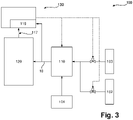
- the apparatus 100 as illustrated in Figure 3 comprises a water supply unit 101, a nitrogen supply unit 102 and a carbon dioxide supply unit 103. In some embodiments, only one of nitrogen 102 and carbon dioxide 103 supply units may be present.
- the supply units 102, 103 for supplying gas(es) may be provided in the form of conventional gas cylinders, storage tanks or devices for producing such gas(es), e.g. air separation units, gas generators or other suitable devices.
- the media from supply units 101, 102 and 103 are transported to the water vessel 110, which may be controlled regarding temperature by a control unit 130, which, in this embodiment, also includes the sensor 116 for determining the water content of the fluid mixture 10 before its introduction into the furnace 120.
- the water content or dew point of the atmosphere inside the furnace may also be determined (117).
- the procedure for preparing the fluid mixture according to this embodiment has already been described in detail in connection with Figure 1 .
- the media from supply units 101, 102 and 103 are directly supplied to the furnace 120 and injected thereto.
- the water content of the atmosphere in the furnace 120 may be controlled by adjusting regulating valves in a flow path between the individual supply units 101, 102, 103 and the furnace 120.
- These regulating valves may, for example, be controlled by the control unit 130, particularly electronically, pneumatically, hydraulically or in any other suitable manner, including a combination of the mentioned possibilities.
- the media from supply units 101, 102 and 103 are united or mixed upstream of the furnace 120 to prepare the fluid mixture which is then introduced into the furnace 120.
- Sensor 116 is used to determine the water content of the fluid mixture 10.
- an additional sensor 117 may be arranged inside the furnace 120 or downstream thereof, in order to analyze the actual composition of the atmosphere within the furnace 120 and/or to verify the result of the dew point measurement of sensor 116.
- a desired water content of the furnace atmosphere for oxidative post treatment may be in the range of 2.5% to 10% by volume in a cold state, i.e. in wet conditions.
- the water content may dramatically increase regarding volume, since at elevated temperatures, all the water contained within the atmosphere in furnace 120 is in gaseous or vapor state.
- the water content is therefore expressed as dew point of the furnace atmosphere lying preferably in the range of 10 °C to 30 °C.
- the dew point can either be determined by simultaneous measurement of relative humidity and temperature, capacity thin-film polymer sensor or directly, for example, using a reflectivity of a periodically cooled mirror. The determined dew point may be used to adjust the water content in the furnace atmosphere to a desired specification, as described above.
- FIG. 2 an advantageous embodiment of a method according to the invention is illustrated in a schematic flow diagram and generally referred to as 200.
- references regarding components of an apparatus refer to the apparatus 100 described above in connection with figures 1 and 3 .
- a first step 210 of the method 200 an article 125 to be oxidatively post-treated is placed in the furnace 120.
- the furnace may then be heated to a desired treatment temperature level in a heating step 220.
- the furnace 120 is used not only for the oxidative post-treatment, but also for the previously performed nitridization or nitrocarburization treatment of the article 125.
- steps 210 and 220 may be omitted, as the article 125 may already be in the furnace 120 and the furnace may already have the desired temperature or a higher (or lower) temperature, so that, for example, only cooling down, or heating up, to the desired temperature may be required, instead of the described steps 210, 220.
- a fluid mixture comprising water and a gas, particularly nitrogen and/or carbon dioxide, is provided.
- the composition of such a mixture may be regulated by adjusting a gas flow rate and/or a temperature of water within the vessel 110. Therefore, e.g. a pressure of the gas may be set or adjusted to a desired value by controlling the gas regulator or compressor 112. It may also be advantageous to provide for a control mechanism for bubble size and/or amount, for example by providing several sets of perforated gas pipes inside the vessel 110, such that each set of pipes may be individually fed with the gas.
- Step 230 may therefore include measuring the momentary composition and adjusting the mentioned influencing parameters like, for example, pressure and/or temperature and/or bubble size and number.
- the so prepared fluid mixture in which water may be present in vapor and/or liquid form, particularly in the form of mist droplets, is then transported to the furnace 120 via pipe(s) 10.
- a step 240 the furnace 120 is kept at the desired processing temperature level for a predefined period of time, which may be chosen according to a required layer thickness of an oxide layer produced by the method 200.
- a temperature program may be followed, i.e. one or more predefined temperature ramps may be provided and the temperature of the furnace 120 may be adjusted to follow the one or more temperature ramps.
- a step 250 may follow for cooling down or quenching the article 125 and removing it from the controlled atmosphere within the furnace 120.
- the method 200 may then return to step 210 to go through a subsequent treatment cycle for one or more other articles 125.
- steps described above are not necessarily performed in the order mentioned or in the form of distinct steps altogether. Some of these steps may, by way of example, be performed in a different, e.g. reversed, order or simultaneously. Some steps may be performed combined as an integrated step or even be omitted without departing from the scope of the present invention.
- the stepwise description of the method 200 was chosen for readability and illustration purposes only and is in no way to be understood in a limiting manner.
Landscapes
- Chemical & Material Sciences (AREA)
- Engineering & Computer Science (AREA)
- Mechanical Engineering (AREA)
- Chemical Kinetics & Catalysis (AREA)
- Materials Engineering (AREA)
- Metallurgy (AREA)
- Organic Chemistry (AREA)
- General Engineering & Computer Science (AREA)
- Solid-Phase Diffusion Into Metallic Material Surfaces (AREA)
Abstract
Description
- The present invention relates to a method of oxidative post-processing of a nitrided or nitrocarburized article (or workpiece or another object) and to an apparatus for carrying out such a method
- Nitrocarburizing and nitriding of steel or other iron based metal objects produces a hard and smooth surface on the treated objects. Post-treatment oxidation of the surface can further enhance corrosion resistance and the visual appearance of the object's surface.
- The present invention proposes a method of oxidative post-processing of a nitrided or nitrocarburized article and an apparatus for carrying out the same with the features of the independent claims. Advantageous embodiments are subject-matter of the dependent claims and the description herein below.
- The invention makes use of water vapor as an oxidant and uses otherwise gases which are generally present at heat treatment facilities as further oxidizing agents and/or dilutants for the water vapor. Thereby, the oxidative post-treatment can be carried out in a controlled manner with high precision with less expected furnace wear and maintenance resulting in improved furnace lifetime.
- A method according to the invention comprises providing the article in a furnace, preparing a fluid mixture containing at least water and one or more of carbon dioxide and nitrogen, controlling the water content of the fluid mixture, providing the fluid mixture to the furnace, and heating the furnace, preferably to a temperature level in the range of 400 °C to 600 °C. Under these process conditions, water vapor as well as carbon dioxide serve as oxidizing agents with respect to the nitrided or nitrocarburized surface, respectively.
- The diluting effect of the admixed gas minimizes the negative effects a moist furnace could have on subsequent processes and abolishes or at least reduces the need for drying steps between subsequent processes.
- As mentioned, nitrocaburizing and nitriding are processes used to harden iron based metal objects. Typical examples of objects or articles, to which such processes are applied, include, without limitation, gun or rifle barrels and slides, bearings, drills, spindles, gears, dies, hydraulic pistons and other parts which during use generally come into dynamic contact with other similarly hard surfaces and are therefore prone to friction induced wear.
-
US 2007/0251605 A1 proposes a process for producing highly corrosion-resistant articles made of steel by subjecting the surface of a nitride steel article to an oxidizing heat treatment. The heat treatment atmosphere contains for example air and steam at a volume ratio of 50:50. However, such an oxidizing process is hard to control since the air has an undefined water content. - Therefore, the invention proposes to control the water content and in particular the dew point of the fluid mixture before it is introduced into the furnace. The dew point depends on the moisture content of the gases which are blended to produce the fluid mixture and it is independent of the temperature contrary to the relative humidity which is temperature dependent.
- By the inventive control of the water content or dew point prior to introducing the fluid mixture into the furnace it is possible to achieve well-defined oxidizing conditions in the furnace. The degree of oxidation is a result of the moisture inside the furnace which is controlled by means of the dew point measurement and of the furnace temperature.
- Advantageously, the fluid mixture is prepared such that a dew point of the mixture under a pressure in the range of 1 - 50 Pa gauge (above atmospheric pressure) that is present in the furnace during heating is in the range of 0 °C to 50 °C, preferably in the range of 10 °C to 30 °C. Under such conditions, the furnace is left dry enough directly after the treatment of the articles, which results in faster conditioning and shorter overall production cycle duration.
- Preferably, preparing the fluid mixture comprises flowing/ducting a gas containing one or more of carbon dioxide and nitrogen through a vessel containing liquid water at a temperature level in the range of 20 to 100°C, preferably between 20 and 50 °C. Gas flow rates and water temperatures are adjusted and preferably controlled with respect to the respective furnace and process in question. This is a very cost-effective and highly controllable method of providing vapor in predefined quantities. Particularly, control parameters like mass flow rate of the gas, dispersion of the gas within the water vessel and water temperature can be easily controlled and have a significant effect on the resulting composition and dew point of the fluid mixture.
- The furnace is preferably kept in a heated state for a period of time chosen such that a thickness of an oxide layer afforded by the method on the article reaches or exceeds 1 µm but does not exceed 3 µm. Heat treatment duration is a major factor influencing the quality of the final product, thereby enabling precise control by adjusting this duration.
- In another aspect, the invention proposes an apparatus for carrying out all the steps discussed in relation to the proposed method. The apparatus, therefore, profits from the same advantages as the method.
- Such an apparatus comprises a furnace configured to accommodate at least one nitrided or nitrocarburized article and to be heated to a temperature level preferably in the range of 400 to 600 °C, a fluid mixture providing device, configured to provide a fluid mixture containing at least water and one or more of carbon dioxide and nitrogen to the furnace and means for determining the water content or dew point of the fluid mixture before it is provided to the furnace. The apparatus preferably comprises means connecting the fluid mixture providing device to the furnace to transport the fluid mixture into the furnace while the furnace is heated.
- Preferably, the apparatus further comprises means for carrying out a method as set out above. For example, such means can comprise a water vessel equipped with piping to introduce a gas stream below the surface of water within the vessel in order to enrich introduced gas in water content. The water vessel may also be provided with a heating device to controllably heat water contained within the vessel to a desired temperature. Further, the apparatus comprises a device to measure water content within the fluid mixture. For example such devices may include one or more of a dew point measuring device, a partial water vapor pressure measuring device, a hygrometer, or another suitable instrument.
- The furnace may be provided with any suitable type of heater, including but not limited to a burner, an electric heater based on resistive heating, a heat exchanger or combinations thereof. Preferably, an inner wall of the furnace comprises a moisture resistant material, such as (non-porous) ceramics, stainless steel, titanium or similarly suitable materials. Brick and/or fiber insulated furnaces are optional but generally less suited where moist processes are combined with drier processes. For such cases the invention offers a small but controllable process window.
- Further advantages and embodiments of the invention will be discussed in connection with the appended drawings and the description thereof.
- It is to be understood that the features mentioned and discussed herein are not only useable in the combinations explicitly mentioned, but can also be used in different combinations thereof or alone, without departing from the scope of the present invention as defined in the appended claims.
- The invention is described in further detail herein below with reference to an exemplary embodiment that is illustrated schematically in the drawings.
-
-
Figure 1 shows an advantageous embodiment of an apparatus according to the invention in the form of a simplified block diagram. -
Figure 2 shows an advantageous embodiment of a method according to the invention in a schematic flow diagram. -
Figure 3 schematically shows alternative advantageous embodiments of an apparatus according to the invention. - In
Figure 1 , an advantageous embodiment of an apparatus according to the invention is illustrated in the form of a simplified block diagram and collectively referred to with 100. - The
apparatus 100, in the depicted example, comprises awater vessel 110, which is provided with water via apump 114. A gas stream comprising carbon dioxide and/or nitrogen is introduced into thewater vessel 110, particularly making use of the gas pressure originating from a source of supply 112 (e.g. tank with vaporizer, bundle or similar, gas regulators for keeping the pressure stable). The introduction is effected on a geodetic level which is sub-surface with respect to the water in thevessel 110, such that the introduced gas forms bubbles within the water in thevessel 110 in order to increase a contact surface area between the gas and the water to enhance water uptake into the gas. - One or
more pipes 10 connect thewater vessel 110 to afurnace 120 of theapparatus 100. Asensor 116 is arranged in fluid contact with the one ormore pipes 10 and monitors a composition of a gas water mixture running through the pipe(s) 10. Thesensor 116 may, for example, comprise a dew point measuring device, such that the water content in the mixture running through pipe(s) 10 is determined. - The
furnace 120 comprises a heater and is configured to accommodate at least onearticle 125 to be treated. One ormore exhaust pipes 20 lead from the furnace to an external atmosphere. The exhaust pipe(s) 20 may be equipped with pilot flames, filters, condensers, washers or other after-treatment devices, e.g. to comply with environmental protection regulations, and/or heat exchangers in order to recuperate excessive heat at least partially from exhaust gases leaving thefurnace 120. - In
Figure 3 , alternative embodiments of such anapparatus 100 are shown. Like reference signs are used for like components and not necessarily all of them are repeatedly discussed, for reasons of conciseness. Compared to theapparatus 100 as depicted inFigure 1 , here, two different alternatives for preparing the fluid mixture are illustrated. One alternative, corresponding to a preparation as described in relation toFigure 1 , is illustrated with solid lines for the connection of the different components. - The
apparatus 100 as illustrated inFigure 3 comprises awater supply unit 101, anitrogen supply unit 102 and a carbondioxide supply unit 103. In some embodiments, only one ofnitrogen 102 andcarbon dioxide 103 supply units may be present. Thesupply units supply units water vessel 110, which may be controlled regarding temperature by acontrol unit 130, which, in this embodiment, also includes thesensor 116 for determining the water content of thefluid mixture 10 before its introduction into thefurnace 120. In addition, the water content or dew point of the atmosphere inside the furnace may also be determined (117). The procedure for preparing the fluid mixture according to this embodiment has already been described in detail in connection withFigure 1 . - The media from
supply units furnace 120 and injected thereto. In such a case, the water content of the atmosphere in thefurnace 120 may be controlled by adjusting regulating valves in a flow path between theindividual supply units furnace 120. These regulating valves may, for example, be controlled by thecontrol unit 130, particularly electronically, pneumatically, hydraulically or in any other suitable manner, including a combination of the mentioned possibilities. The media fromsupply units furnace 120 to prepare the fluid mixture which is then introduced into thefurnace 120.Sensor 116 is used to determine the water content of thefluid mixture 10. Further, anadditional sensor 117 may be arranged inside thefurnace 120 or downstream thereof, in order to analyze the actual composition of the atmosphere within thefurnace 120 and/or to verify the result of the dew point measurement ofsensor 116. - Independent of the specific design of
apparatus 100, a desired water content of the furnace atmosphere for oxidative post treatment may be in the range of 2.5% to 10% by volume in a cold state, i.e. in wet conditions. During operation of the furnace, therefore, the water content may dramatically increase regarding volume, since at elevated temperatures, all the water contained within the atmosphere infurnace 120 is in gaseous or vapor state. For more precisely reproducible results, the water content is therefore expressed as dew point of the furnace atmosphere lying preferably in the range of 10 °C to 30 °C. The dew point can either be determined by simultaneous measurement of relative humidity and temperature, capacity thin-film polymer sensor or directly, for example, using a reflectivity of a periodically cooled mirror. The determined dew point may be used to adjust the water content in the furnace atmosphere to a desired specification, as described above. - In
Figure 2 , an advantageous embodiment of a method according to the invention is illustrated in a schematic flow diagram and generally referred to as 200. - References regarding components of an apparatus refer to the
apparatus 100 described above in connection withfigures 1 and3 . - In a
first step 210 of themethod 200, anarticle 125 to be oxidatively post-treated is placed in thefurnace 120. The furnace may then be heated to a desired treatment temperature level in aheating step 220. - It may be possible, in some embodiments, that the
furnace 120 is used not only for the oxidative post-treatment, but also for the previously performed nitridization or nitrocarburization treatment of thearticle 125. In such cases, one or both ofsteps article 125 may already be in thefurnace 120 and the furnace may already have the desired temperature or a higher (or lower) temperature, so that, for example, only cooling down, or heating up, to the desired temperature may be required, instead of the describedsteps - In a
step 230, a fluid mixture comprising water and a gas, particularly nitrogen and/or carbon dioxide, is provided. In the exemplary embodiment of anapparatus 100, depicted infigure 1 , the composition of such a mixture may be regulated by adjusting a gas flow rate and/or a temperature of water within thevessel 110. Therefore, e.g. a pressure of the gas may be set or adjusted to a desired value by controlling the gas regulator orcompressor 112. It may also be advantageous to provide for a control mechanism for bubble size and/or amount, for example by providing several sets of perforated gas pipes inside thevessel 110, such that each set of pipes may be individually fed with the gas. By feeding more sets of pipes, more and potentially smaller bubbles may be formed, whereas feeding gas to fewer (sets of) pipes may result in larger and/or fewer bubbles. The more bubbles are formed instep 230 and the smaller the formed bubbles are, the larger the relative amount of water that is taken up by the gas. A similar observation will hold for the water temperature: the higher the temperature, the higher the saturation pressure, leading to increasing relative amounts of water in the mixture with increasing water temperature within thevessel 110. - Preferably, the water amount is adjusted or regulated according to an actual composition of the mixture as determined by the
sensor 116. Step 230 may therefore include measuring the momentary composition and adjusting the mentioned influencing parameters like, for example, pressure and/or temperature and/or bubble size and number. - The so prepared fluid mixture, in which water may be present in vapor and/or liquid form, particularly in the form of mist droplets, is then transported to the
furnace 120 via pipe(s) 10. - In a
step 240, thefurnace 120 is kept at the desired processing temperature level for a predefined period of time, which may be chosen according to a required layer thickness of an oxide layer produced by themethod 200. In some embodiments, a temperature program may be followed, i.e. one or more predefined temperature ramps may be provided and the temperature of thefurnace 120 may be adjusted to follow the one or more temperature ramps. - A
step 250 may follow for cooling down or quenching thearticle 125 and removing it from the controlled atmosphere within thefurnace 120. - The
method 200 may then return to step 210 to go through a subsequent treatment cycle for one or moreother articles 125. - It should be noted, that the steps described above are not necessarily performed in the order mentioned or in the form of distinct steps altogether. Some of these steps may, by way of example, be performed in a different, e.g. reversed, order or simultaneously. Some steps may be performed combined as an integrated step or even be omitted without departing from the scope of the present invention. The stepwise description of the
method 200 was chosen for readability and illustration purposes only and is in no way to be understood in a limiting manner.
Claims (9)
- Method (200) of oxidative post-processing of a nitrided or nitrocarburized article (125), comprisingproviding (210) the article (125) in a furnace (120),preparing (230) a fluid mixture containing at least water and one or more of carbon dioxide and nitrogen,controlling the water content, and in particular the dew point, of the fluid mixture andproviding (230) the fluid mixture to the furnace (120), andheating (220, 240) the furnace (120) to a predetermined temperature.
- Method (200) according to claim 1, wherein the predetermined temperature is in the range of 400 °C to 600 °C, particularly 450 °C to 580 °C.
- Method (200) according to claim 1 or 2, wherein the fluid mixture is prepared such that a dew point of the mixture under a pressure that is present in the furnace (120) during heating (220, 240) is in the range of 0 °C to 50 °C, preferably in the range of 10 °C to 30 °C.
- Method (200) according to any one of claims 1 to 3, wherein preparing (230) the fluid mixture comprises flowing a gas containing one or more of carbon dioxide and nitrogen through a vessel (110) containing liquid water at a temperature level in the range of 20 to 100 °C, preferably between 20 and 50 °C.
- Method (200) according to any one of the preceding claims, wherein the furnace (120) is kept in a heated state (240) for a period of time chosen such that a thickness of an oxide layer on the article (125), afforded by the method (200), reaches or exceeds 1 µm, but does not exceed 3 µm.
- Apparatus (100) for oxidative post-processing of a nitrided or nitrocarburized article (125), comprising- a furnace (120) configured to accommodate at least one nitrided or nitrocarburized article (125) and to be heated to a predetermined temperature,- a fluid mixture providing device (110) configured to provide a fluid mixture containing at least water and one or more of carbon dioxide and nitrogen,- means for determining the water content of the fluid mixture and- means for providing the fluid mixture to the furnace (120).
- Apparatus (100) according to claim 6, further comprising means (10) connecting the fluid mixture providing device (110) to the furnace (120) to transport the fluid mixture into the furnace (120) while the furnace (120) is heated.
- Apparatus (100) according to any of claims 6 or 7, wherein the fluid mixture providing device comprises a water vessel and at least one of a carbon dioxide supply and a nitrogen supply connected to said water vessel.
- Apparatus (100) according to one of claims 6 to 8, further comprising means (112, 114, 116) configured to carry out a method (200) according to any of claims 1 through 5.
Applications Claiming Priority (1)
| Application Number | Priority Date | Filing Date | Title |
|---|---|---|---|
| EP20020584.7A EP4008802A1 (en) | 2020-12-02 | 2020-12-02 | Method of and apparatus for oxidative post-processing of a nitrided or nitrocarburized article |
Publications (1)
| Publication Number | Publication Date |
|---|---|
| EP4008803A1 true EP4008803A1 (en) | 2022-06-08 |
Family
ID=73726530
Family Applications (2)
| Application Number | Title | Priority Date | Filing Date |
|---|---|---|---|
| EP20020584.7A Withdrawn EP4008802A1 (en) | 2020-12-02 | 2020-12-02 | Method of and apparatus for oxidative post-processing of a nitrided or nitrocarburized article |
| EP21020605.8A Pending EP4008803A1 (en) | 2020-12-02 | 2021-12-01 | Method of and apparatus for oxidative post-processing of a nitrided or nitrocarburized article |
Family Applications Before (1)
| Application Number | Title | Priority Date | Filing Date |
|---|---|---|---|
| EP20020584.7A Withdrawn EP4008802A1 (en) | 2020-12-02 | 2020-12-02 | Method of and apparatus for oxidative post-processing of a nitrided or nitrocarburized article |
Country Status (1)
| Country | Link |
|---|---|
| EP (2) | EP4008802A1 (en) |
Citations (6)
| Publication number | Priority date | Publication date | Assignee | Title |
|---|---|---|---|---|
| US3655172A (en) * | 1970-04-14 | 1972-04-11 | Glenn R Ingels | Saturated fluid mixtures generator |
| EP0229325A2 (en) * | 1981-10-15 | 1987-07-22 | LUCAS INDUSTRIES public limited company | Method of manufacturing a corrosion resistant steel component |
| EP0299625A2 (en) * | 1987-07-17 | 1989-01-18 | LUCAS INDUSTRIES public limited company | Manufacture of corrosion resistant steel components |
| US4859251A (en) * | 1987-03-07 | 1989-08-22 | Kabushiki Kaisha Toshiba | Furnace for formation of black oxide film on the surface of thin metal sheet and method for formation of black oxide film on the surface of shadow mask material by use of said furnace |
| US20070251605A1 (en) | 2006-05-01 | 2007-11-01 | Young Hee Kim | Method for producing highly corrosion-resistant colored article made of steel |
| WO2014002120A1 (en) * | 2012-06-26 | 2014-01-03 | Cavina Fulvio Fabrizio | Process and plant for the anti-oxidising surface treatment of steel parts |
-
2020
- 2020-12-02 EP EP20020584.7A patent/EP4008802A1/en not_active Withdrawn
-
2021
- 2021-12-01 EP EP21020605.8A patent/EP4008803A1/en active Pending
Patent Citations (6)
| Publication number | Priority date | Publication date | Assignee | Title |
|---|---|---|---|---|
| US3655172A (en) * | 1970-04-14 | 1972-04-11 | Glenn R Ingels | Saturated fluid mixtures generator |
| EP0229325A2 (en) * | 1981-10-15 | 1987-07-22 | LUCAS INDUSTRIES public limited company | Method of manufacturing a corrosion resistant steel component |
| US4859251A (en) * | 1987-03-07 | 1989-08-22 | Kabushiki Kaisha Toshiba | Furnace for formation of black oxide film on the surface of thin metal sheet and method for formation of black oxide film on the surface of shadow mask material by use of said furnace |
| EP0299625A2 (en) * | 1987-07-17 | 1989-01-18 | LUCAS INDUSTRIES public limited company | Manufacture of corrosion resistant steel components |
| US20070251605A1 (en) | 2006-05-01 | 2007-11-01 | Young Hee Kim | Method for producing highly corrosion-resistant colored article made of steel |
| WO2014002120A1 (en) * | 2012-06-26 | 2014-01-03 | Cavina Fulvio Fabrizio | Process and plant for the anti-oxidising surface treatment of steel parts |
Also Published As
| Publication number | Publication date |
|---|---|
| EP4008802A1 (en) | 2022-06-08 |
Similar Documents
| Publication | Publication Date | Title |
|---|---|---|
| JP6020605B2 (en) | Method for producing galvannealed steel sheet | |
| US10752975B2 (en) | Method of producing galvannealed steel sheet | |
| US20080073002A1 (en) | Carburization treatment method and carburization treatment apparatus | |
| EP3276037B1 (en) | Method of manufacturing a hot-dip galvanized steel sheet | |
| EP2541177A2 (en) | Fluid delivery system for an atmospheric furnace used for treating one or more articles | |
| EP3369836B1 (en) | Method for manufacturing hot-dip galvanized steel sheet | |
| CN107723613B (en) | A kind of paper cutting blade wide cut steel band and its manufacturing method | |
| JP2016204744A (en) | Continuous molten metal plating method, and continuous molten metal plating facility | |
| CN109279575A (en) | Methanol low-temperature decomposing device | |
| EP4008802A1 (en) | Method of and apparatus for oxidative post-processing of a nitrided or nitrocarburized article | |
| TR201808830T4 (en) | Method for treating steels. | |
| EP0040094A1 (en) | Carburizing process utilizing atmospheres generated from nitrogen-ethanol based mixtures | |
| CN114761585B (en) | Heat treatment equipment | |
| DE69411022T2 (en) | METHOD AND DEVICE FOR THE CONTROLLED PRODUCTION AND SUPPLY OF A GAS ATMOSPHERE WITH AT LEAST TWO COMPONENTS AND USE IN EQUIPMENT FOR THERMAL OR CARBONATING TREATMENT | |
| DE69829543T2 (en) | Method for generating water vapor | |
| JP6269547B2 (en) | Continuous hot dip galvanizing apparatus and method for producing hot dip galvanized steel sheet | |
| CN104976929B (en) | One kind simulation compressed air source unit | |
| CN103834909A (en) | Heat treatment method of bearing steel | |
| DE102018118861A1 (en) | Provision of a synthetic exhaust gas flow | |
| CN121295091A (en) | A method to reduce uneven vacuum carburizing | |
| KR20250153260A (en) | Method for heating steel semi-finished products in a furnace and related furnaces | |
| JPS5896866A (en) | Controlling method for quantity of carburization in vaccum carburization treatment | |
| JPH0717942B2 (en) | Atmosphere control method in continuous annealing furnace | |
| JPH01263216A (en) | Device for supplying humidification in atmospheric gas | |
| JPS59222571A (en) | Method for gas-carburizing steel |
Legal Events
| Date | Code | Title | Description |
|---|---|---|---|
| PUAI | Public reference made under article 153(3) epc to a published international application that has entered the european phase |
Free format text: ORIGINAL CODE: 0009012 |
|
| STAA | Information on the status of an ep patent application or granted ep patent |
Free format text: STATUS: THE APPLICATION HAS BEEN PUBLISHED |
|
| AK | Designated contracting states |
Kind code of ref document: A1 Designated state(s): AL AT BE BG CH CY CZ DE DK EE ES FI FR GB GR HR HU IE IS IT LI LT LU LV MC MK MT NL NO PL PT RO RS SE SI SK SM TR |
|
| STAA | Information on the status of an ep patent application or granted ep patent |
Free format text: STATUS: REQUEST FOR EXAMINATION WAS MADE |
|
| 17P | Request for examination filed |
Effective date: 20221208 |
|
| RBV | Designated contracting states (corrected) |
Designated state(s): AL AT BE BG CH CY CZ DE DK EE ES FI FR GB GR HR HU IE IS IT LI LT LU LV MC MK MT NL NO PL PT RO RS SE SI SK SM TR |