EP4008522A1 - Electro-spinning/writing system and corresponding method - Google Patents
Electro-spinning/writing system and corresponding method Download PDFInfo
- Publication number
- EP4008522A1 EP4008522A1 EP20211278.5A EP20211278A EP4008522A1 EP 4008522 A1 EP4008522 A1 EP 4008522A1 EP 20211278 A EP20211278 A EP 20211278A EP 4008522 A1 EP4008522 A1 EP 4008522A1
- Authority
- EP
- European Patent Office
- Prior art keywords
- collector
- polymer material
- liquid
- head
- Prior art date
- Legal status (The legal status is an assumption and is not a legal conclusion. Google has not performed a legal analysis and makes no representation as to the accuracy of the status listed.)
- Withdrawn
Links
- 238000001523 electrospinning Methods 0.000 title claims abstract description 24
- 238000000034 method Methods 0.000 title claims description 34
- 239000002861 polymer material Substances 0.000 claims abstract description 187
- 239000007788 liquid Substances 0.000 claims abstract description 125
- 238000006073 displacement reaction Methods 0.000 claims abstract description 31
- 229920000642 polymer Polymers 0.000 claims description 61
- 230000008021 deposition Effects 0.000 claims description 59
- 230000000977 initiatory effect Effects 0.000 claims description 4
- 238000000151 deposition Methods 0.000 description 60
- 230000005684 electric field Effects 0.000 description 29
- 230000001965 increasing effect Effects 0.000 description 14
- 229920005594 polymer fiber Polymers 0.000 description 14
- -1 polypropylene Polymers 0.000 description 11
- 239000000463 material Substances 0.000 description 7
- 239000007787 solid Substances 0.000 description 7
- 230000001276 controlling effect Effects 0.000 description 6
- 230000000694 effects Effects 0.000 description 6
- LFQSCWFLJHTTHZ-UHFFFAOYSA-N Ethanol Chemical compound CCO LFQSCWFLJHTTHZ-UHFFFAOYSA-N 0.000 description 4
- 239000000835 fiber Substances 0.000 description 4
- 238000004519 manufacturing process Methods 0.000 description 4
- 239000002904 solvent Substances 0.000 description 4
- OKKJLVBELUTLKV-UHFFFAOYSA-N Methanol Chemical compound OC OKKJLVBELUTLKV-UHFFFAOYSA-N 0.000 description 3
- 239000008187 granular material Substances 0.000 description 3
- 230000010287 polarization Effects 0.000 description 3
- 238000007789 sealing Methods 0.000 description 3
- HEDRZPFGACZZDS-UHFFFAOYSA-N Chloroform Chemical compound ClC(Cl)Cl HEDRZPFGACZZDS-UHFFFAOYSA-N 0.000 description 2
- KFZMGEQAYNKOFK-UHFFFAOYSA-N Isopropanol Chemical compound CC(C)O KFZMGEQAYNKOFK-UHFFFAOYSA-N 0.000 description 2
- ISWSIDIOOBJBQZ-UHFFFAOYSA-N Phenol Chemical compound OC1=CC=CC=C1 ISWSIDIOOBJBQZ-UHFFFAOYSA-N 0.000 description 2
- 239000004734 Polyphenylene sulfide Substances 0.000 description 2
- 239000000654 additive Substances 0.000 description 2
- 230000000996 additive effect Effects 0.000 description 2
- 238000004590 computer program Methods 0.000 description 2
- 238000001816 cooling Methods 0.000 description 2
- 230000000249 desinfective effect Effects 0.000 description 2
- 238000009826 distribution Methods 0.000 description 2
- 238000007787 electrohydrodynamic spraying Methods 0.000 description 2
- 238000001704 evaporation Methods 0.000 description 2
- 239000012530 fluid Substances 0.000 description 2
- 238000007654 immersion Methods 0.000 description 2
- 239000007943 implant Substances 0.000 description 2
- 230000007246 mechanism Effects 0.000 description 2
- 239000000155 melt Substances 0.000 description 2
- 230000008018 melting Effects 0.000 description 2
- 238000002844 melting Methods 0.000 description 2
- 239000012466 permeate Substances 0.000 description 2
- 229920000747 poly(lactic acid) Polymers 0.000 description 2
- 239000004626 polylactic acid Substances 0.000 description 2
- 229920000069 polyphenylene sulfide Polymers 0.000 description 2
- 230000008569 process Effects 0.000 description 2
- 230000000717 retained effect Effects 0.000 description 2
- 238000004088 simulation Methods 0.000 description 2
- 238000009987 spinning Methods 0.000 description 2
- XLYOFNOQVPJJNP-UHFFFAOYSA-N water Substances O XLYOFNOQVPJJNP-UHFFFAOYSA-N 0.000 description 2
- WSQZNZLOZXSBHA-UHFFFAOYSA-N 3,8-dioxabicyclo[8.2.2]tetradeca-1(12),10,13-triene-2,9-dione Chemical compound O=C1OCCCCOC(=O)C2=CC=C1C=C2 WSQZNZLOZXSBHA-UHFFFAOYSA-N 0.000 description 1
- QZCLKYGREBVARF-UHFFFAOYSA-N Acetyl tributyl citrate Chemical compound CCCCOC(=O)CC(C(=O)OCCCC)(OC(C)=O)CC(=O)OCCCC QZCLKYGREBVARF-UHFFFAOYSA-N 0.000 description 1
- 239000004952 Polyamide Substances 0.000 description 1
- 239000004698 Polyethylene Substances 0.000 description 1
- 239000004743 Polypropylene Substances 0.000 description 1
- 239000004793 Polystyrene Substances 0.000 description 1
- 229920002472 Starch Polymers 0.000 description 1
- 238000005452 bending Methods 0.000 description 1
- 230000009286 beneficial effect Effects 0.000 description 1
- 239000005313 bioactive glass Substances 0.000 description 1
- 230000008859 change Effects 0.000 description 1
- 239000000470 constituent Substances 0.000 description 1
- 125000004122 cyclic group Chemical group 0.000 description 1
- 230000001419 dependent effect Effects 0.000 description 1
- 238000010292 electrical insulation Methods 0.000 description 1
- 230000008020 evaporation Effects 0.000 description 1
- 239000013538 functional additive Substances 0.000 description 1
- 238000010438 heat treatment Methods 0.000 description 1
- 229910052588 hydroxylapatite Inorganic materials 0.000 description 1
- 230000001939 inductive effect Effects 0.000 description 1
- 230000003993 interaction Effects 0.000 description 1
- 239000000203 mixture Substances 0.000 description 1
- QGLKJKCYBOYXKC-UHFFFAOYSA-N nonaoxidotritungsten Chemical compound O=[W]1(=O)O[W](=O)(=O)O[W](=O)(=O)O1 QGLKJKCYBOYXKC-UHFFFAOYSA-N 0.000 description 1
- 239000003921 oil Substances 0.000 description 1
- 230000003287 optical effect Effects 0.000 description 1
- 239000002245 particle Substances 0.000 description 1
- XYJRXVWERLGGKC-UHFFFAOYSA-D pentacalcium;hydroxide;triphosphate Chemical compound [OH-].[Ca+2].[Ca+2].[Ca+2].[Ca+2].[Ca+2].[O-]P([O-])([O-])=O.[O-]P([O-])([O-])=O.[O-]P([O-])([O-])=O XYJRXVWERLGGKC-UHFFFAOYSA-D 0.000 description 1
- 229920000070 poly-3-hydroxybutyrate Polymers 0.000 description 1
- 229920002647 polyamide Polymers 0.000 description 1
- 229920001610 polycaprolactone Polymers 0.000 description 1
- 229920002530 polyetherether ketone Polymers 0.000 description 1
- 229920000573 polyethylene Polymers 0.000 description 1
- 229920001223 polyethylene glycol Polymers 0.000 description 1
- 229920002959 polymer blend Polymers 0.000 description 1
- 229920001155 polypropylene Polymers 0.000 description 1
- 229920002223 polystyrene Polymers 0.000 description 1
- 230000001105 regulatory effect Effects 0.000 description 1
- 235000019698 starch Nutrition 0.000 description 1
- 239000008107 starch Substances 0.000 description 1
- 239000000126 substance Substances 0.000 description 1
- 239000010409 thin film Substances 0.000 description 1
- 229910001930 tungsten oxide Inorganic materials 0.000 description 1
- 229920002554 vinyl polymer Polymers 0.000 description 1
Images


Classifications
-
- B—PERFORMING OPERATIONS; TRANSPORTING
- B29—WORKING OF PLASTICS; WORKING OF SUBSTANCES IN A PLASTIC STATE IN GENERAL
- B29C—SHAPING OR JOINING OF PLASTICS; SHAPING OF MATERIAL IN A PLASTIC STATE, NOT OTHERWISE PROVIDED FOR; AFTER-TREATMENT OF THE SHAPED PRODUCTS, e.g. REPAIRING
- B29C64/00—Additive manufacturing, i.e. manufacturing of three-dimensional [3D] objects by additive deposition, additive agglomeration or additive layering, e.g. by 3D printing, stereolithography or selective laser sintering
- B29C64/10—Processes of additive manufacturing
- B29C64/106—Processes of additive manufacturing using only liquids or viscous materials, e.g. depositing a continuous bead of viscous material
- B29C64/118—Processes of additive manufacturing using only liquids or viscous materials, e.g. depositing a continuous bead of viscous material using filamentary material being melted, e.g. fused deposition modelling [FDM]
-
- B—PERFORMING OPERATIONS; TRANSPORTING
- B29—WORKING OF PLASTICS; WORKING OF SUBSTANCES IN A PLASTIC STATE IN GENERAL
- B29C—SHAPING OR JOINING OF PLASTICS; SHAPING OF MATERIAL IN A PLASTIC STATE, NOT OTHERWISE PROVIDED FOR; AFTER-TREATMENT OF THE SHAPED PRODUCTS, e.g. REPAIRING
- B29C64/00—Additive manufacturing, i.e. manufacturing of three-dimensional [3D] objects by additive deposition, additive agglomeration or additive layering, e.g. by 3D printing, stereolithography or selective laser sintering
- B29C64/20—Apparatus for additive manufacturing; Details thereof or accessories therefor
- B29C64/227—Driving means
- B29C64/232—Driving means for motion along the axis orthogonal to the plane of a layer
-
- B—PERFORMING OPERATIONS; TRANSPORTING
- B29—WORKING OF PLASTICS; WORKING OF SUBSTANCES IN A PLASTIC STATE IN GENERAL
- B29C—SHAPING OR JOINING OF PLASTICS; SHAPING OF MATERIAL IN A PLASTIC STATE, NOT OTHERWISE PROVIDED FOR; AFTER-TREATMENT OF THE SHAPED PRODUCTS, e.g. REPAIRING
- B29C64/00—Additive manufacturing, i.e. manufacturing of three-dimensional [3D] objects by additive deposition, additive agglomeration or additive layering, e.g. by 3D printing, stereolithography or selective laser sintering
- B29C64/20—Apparatus for additive manufacturing; Details thereof or accessories therefor
- B29C64/255—Enclosures for the building material, e.g. powder containers
-
- B—PERFORMING OPERATIONS; TRANSPORTING
- B29—WORKING OF PLASTICS; WORKING OF SUBSTANCES IN A PLASTIC STATE IN GENERAL
- B29C—SHAPING OR JOINING OF PLASTICS; SHAPING OF MATERIAL IN A PLASTIC STATE, NOT OTHERWISE PROVIDED FOR; AFTER-TREATMENT OF THE SHAPED PRODUCTS, e.g. REPAIRING
- B29C64/00—Additive manufacturing, i.e. manufacturing of three-dimensional [3D] objects by additive deposition, additive agglomeration or additive layering, e.g. by 3D printing, stereolithography or selective laser sintering
- B29C64/20—Apparatus for additive manufacturing; Details thereof or accessories therefor
- B29C64/295—Heating elements
-
- B—PERFORMING OPERATIONS; TRANSPORTING
- B33—ADDITIVE MANUFACTURING TECHNOLOGY
- B33Y—ADDITIVE MANUFACTURING, i.e. MANUFACTURING OF THREE-DIMENSIONAL [3-D] OBJECTS BY ADDITIVE DEPOSITION, ADDITIVE AGGLOMERATION OR ADDITIVE LAYERING, e.g. BY 3-D PRINTING, STEREOLITHOGRAPHY OR SELECTIVE LASER SINTERING
- B33Y10/00—Processes of additive manufacturing
-
- B—PERFORMING OPERATIONS; TRANSPORTING
- B33—ADDITIVE MANUFACTURING TECHNOLOGY
- B33Y—ADDITIVE MANUFACTURING, i.e. MANUFACTURING OF THREE-DIMENSIONAL [3-D] OBJECTS BY ADDITIVE DEPOSITION, ADDITIVE AGGLOMERATION OR ADDITIVE LAYERING, e.g. BY 3-D PRINTING, STEREOLITHOGRAPHY OR SELECTIVE LASER SINTERING
- B33Y30/00—Apparatus for additive manufacturing; Details thereof or accessories therefor
-
- D—TEXTILES; PAPER
- D01—NATURAL OR MAN-MADE THREADS OR FIBRES; SPINNING
- D01D—MECHANICAL METHODS OR APPARATUS IN THE MANUFACTURE OF ARTIFICIAL FILAMENTS, THREADS, FIBRES, BRISTLES OR RIBBONS
- D01D5/00—Formation of filaments, threads, or the like
- D01D5/0007—Electro-spinning
- D01D5/0015—Electro-spinning characterised by the initial state of the material
- D01D5/0023—Electro-spinning characterised by the initial state of the material the material being a polymer melt
-
- D—TEXTILES; PAPER
- D01—NATURAL OR MAN-MADE THREADS OR FIBRES; SPINNING
- D01D—MECHANICAL METHODS OR APPARATUS IN THE MANUFACTURE OF ARTIFICIAL FILAMENTS, THREADS, FIBRES, BRISTLES OR RIBBONS
- D01D5/00—Formation of filaments, threads, or the like
- D01D5/0007—Electro-spinning
- D01D5/0061—Electro-spinning characterised by the electro-spinning apparatus
- D01D5/0076—Electro-spinning characterised by the electro-spinning apparatus characterised by the collecting device, e.g. drum, wheel, endless belt, plate or grid
-
- B—PERFORMING OPERATIONS; TRANSPORTING
- B29—WORKING OF PLASTICS; WORKING OF SUBSTANCES IN A PLASTIC STATE IN GENERAL
- B29K—INDEXING SCHEME ASSOCIATED WITH SUBCLASSES B29B, B29C OR B29D, RELATING TO MOULDING MATERIALS OR TO MATERIALS FOR MOULDS, REINFORCEMENTS, FILLERS OR PREFORMED PARTS, e.g. INSERTS
- B29K2995/00—Properties of moulding materials, reinforcements, fillers, preformed parts or moulds
- B29K2995/0003—Properties of moulding materials, reinforcements, fillers, preformed parts or moulds having particular electrical or magnetic properties, e.g. piezoelectric
- B29K2995/0005—Conductive
Definitions
- the present invention is in the field of additive manufacturing. More precisely, the present invention relates to electro-spinning/writing of polymer structures with an extended build height.
- Additive manufacturing relies on the sequential deposition of a build material to gradually build a complete part from sequentially deposited material layers based on a virtual copy of the intended structure.
- a relative movement between a print-head and a build plate is driven to define the geometry of one material layer in a two-dimensional plane.
- a three-dimensional structure can be progressively constructed.
- Electro-spinning/writing is a technique wherein a flow of a polymer material from an emitter towards a collector is stabilized via an electric field.
- a polymer may be provided in molten form by a conductive nozzle and may be directed from the nozzle onto a conductive collector plate by a high-voltage electric field, in a technique called Melt-Electro(spinning)-Writing.
- the electric field may charge the polymer material and pull the polymer material into streams with a thickness that is smaller than the nozzle diameter while the charged polymer material is attracted by the collector.
- the polymer stream may bridge the gap between the emitter and the collector while cooling and/or evaporating solvent material, such that a solid or solidifying polymer material is deposited on the collector.
- the polymer material may be deposited at a pre-defined position on the collector, or may be spun into thin fibers deposited semi-randomly in a deposition region of the collector. Three-dimensional shapes of the polymer material may then be generated by sequentially depositing multiple layers of the polymer material.
- Wunner et al. disclose a Melt Electrospinning Writing (MEW) system with a spinneret and a collector plate facing each other, wherein an applied high-voltage drives the polymer melt from the spinneret onto the collector.
- MEW Melt Electrospinning Writing
- the collector is dynamically distanced from the spinneret, such that the distance between the topmost layer of the deposited polymer melt and the spinneret remains constant.
- the voltage can be regulated at the same time, such that the electrostatic forces onto the polymer melt remain constant.
- the object of the invention is to provide an improved system for the controlled electro-spinning/writing of larger structures with an extended build height.
- the invention relates to a system for electro-spinning/writing of a polymer material.
- the system comprises a print-head configured to eject the polymer material via a nozzle, a collector configured to receive the polymer material ejected from the nozzle, and a displacement assembly configured to adjust a distance between the print-head and the collector.
- the system further comprises a vat containing or configured to contain a liquid, wherein the vat is further configured to receive the collector, and wherein the displacement assembly is configured to retract the collector and at least a part of the polymer material received by the collector into the liquid in the vat in accordance with a height of the received polymer material.
- the liquid may at least partially offset/mitigate the effect of the deposited polymer structures on the electric field distribution between the nozzle and the collector.
- the liquid in the vat may reduce a spatial variation of the relative dielectric constant and/or may provide a substantially flat potential reference plane close to the plane of deposition, such that the impact of structures protruding along the build direction onto the polymer material ejected by the nozzle can be at least partially compensated.
- the liquid may also shield and/or accept charges in/from the deposited polymer material.
- the liquid may shield electric charges in the deposited polymer material and/or may drain electric charges from the deposited polymer material below the liquid surface.
- a more uniform electric field can be maintained between the nozzle and the uppermost layer of the deposited polymer material, and a deposition accuracy for polymer structures with structures protruding along the build height, e.g. perpendicular to the collector surface, may accordingly be increased as compared to the case where the structures are deposited in a uniform atmosphere, e.g. air, between the emitter and the collector.
- the system may therefore be advantageously employed for deterministic electro-writing of polymer structures, e.g. for the controlled manufacturing of implants or scaffolds for biomedical research applications with well-defined structural geometries.
- the liquid may shield and/or drain charges in/from the deposited polymer material, a maximum height for a manufactured polymer structure may be increased. Accordingly, the system may also be advantageously used in an electrospinning regime when depositing polymer material while applying an electric field between the nozzle and the collector.
- the polymer material may be provided to the print-head in solid or liquid form, such as a solidified polymer or a polymer mixture which can be melted in the print-head, or a polymer material which is dissolved in a solvent.
- the polymer material may comprise polypropylene, polyethylene, polyphenylene sulfide, polyamide, polylactic acid, polyphenylene sulfide, Poly(ether-ether ketone), poly(ethylene-co-vinyl)alcohol, Poly(l-lactic acid), starch, poly(3-hydroxybutyrate), Cyclic butylene terephthalate oligomer, acetyl tributyl citrate, Polystyrene, poly( ⁇ -caprolactone), Polylactide-poly(ethylene-glycol) Poly(vinylidene difluoride), Poly(hydroxymethyl-glycolide-co- ⁇ -caprolactone), Poly(l-lactide-co- ⁇ -caprolactone-co-acrylo
- system and associated method can be generally used for a deposition of polymer fibers with most polymers having sufficient molecular entanglements to not break up into droplets due to Raleigh instabilities during a transfer between the nozzle and the collector.
- system and disclosed techniques may also be advantageously employed for electro-spraying techniques, wherein a sequence of charged polymer droplets is directed from the print-head towards the collector.
- the system comprises a heater configured to melt polymer material to form a polymer melt to be ejected through the nozzle.
- a polymer melt can have a higher viscosity than a polymer solution and may solidify over a shorter collector distance, such as a distance smaller than 10 mm, in particular a distance smaller than 8 mm, such as about 4 mm, between the collector and the nozzle, which may increase a control over the deposition location of the polymer material. Further, polymer melts may retain fewer charges than polymer solutions which may result in increased deposition accuracy and/or a maximum deposition height of the polymer material deposited in multiple layers.
- the polymer material may be fed to the nozzle in the form of filaments or granulates and may be heated in the print-head to form the polymer melt.
- the polymer material may exit the print-head in at least partially liquid form and may be subjected to an electric field applied between a conductive nozzle and a conductive collector facing the print-head.
- the polymer material may be charged in the electric field at the nozzle and may be pulled towards the collector in the electric field.
- the polymer material forms a continuous fluid column extending between the nozzle and the collector, while the polymer stream may taper from the nozzle towards the collector, e.g. form a Taylor cone at the nozzle and taper towards the collector.
- the polymer material may then be jetted from the tip of the Taylor cone towards the collector to form polymer fibers on the collector.
- a voltage is applied between the collector and the print-head, wherein the voltage is suitable for controlling a flow of polymer material from the print-head towards the collector.
- the electric potential may be selected such that a stable fluid column is formed between the nozzle and the collector, wherein a flow of the polymer material may be substantially along the electrical field lines.
- the electric potential may be larger than 100 V, in particular larger than 1 kV, e.g. between 1 kV and 100 kV, to stabilize a stream of the polymer material ejected from the nozzle and/or to direct the polymer material from the nozzle towards the collector.
- system further comprises a voltage source configured to apply a selectable electric potential to the print-head and/or the collector.
- the voltage source may apply electric potentials of opposite polarities to the nozzle and the collector or may apply a selectable electric potential to one of the nozzle and the collector while the other one of the nozzle and the collector is (electrically) grounded.
- the collector is (electrically) grounded, and the nozzle is configured to be held at a selectable electric potential, wherein the selectable electric potential is suitable for controlling a flow of polymer material from the print-head towards the collector.
- an electric field at the nozzle induced by a charged collector may be partially compensated by a polarization of the liquid and may thus vary based on the immersion depth.
- the electric potential at the nozzle may simplify electrical insulation of the system as opposed to applying an electric potential to the at least partially immersed collector.
- the polymer material ejected from the nozzle may be deposited in the form of polymer fibers while the print-head and the collector perform a relative movement in a two-dimensional plane.
- the collector is held in the vat while the print-head moves in a two-dimensional plane to define the geometry of a two-dimensional layer of polymer fibers deposited onto the collector.
- the print-head may continuously deposit polymer fibers onto the collector to progressively deposit multiple layers of polymer fibers.
- the system may be configured to deposit polymer droplets, e.g. in an electro-spraying mode of the print-head.
- the displacement assembly can be configured to move the collector away from the nozzle in accordance with a height of the deposited polymer material.
- the displacement assembly is configured to retract the collector away from the nozzle based on an elapsed time of depositing polymer material on the collector, wherein the collector may be retracted stepwise or continuously.
- the displacement assembly may be configured to retract the collector away from the nozzle based on a deposition height.
- the deposition height may be estimated from an intended structure deposited by the print-head, or may be measured based on a height of a polymer structure received on the collector.
- the displacement assembly is configured to retract the collector away from the nozzle after a predetermined estimated layer height has been deposited by the print-head, such as after each layer or after a predetermined number of layers deposited by the print-head onto the collector.
- the movement of the displacement assembly may be controlled by a control system which may send control signals to an actuator of the displacement assembly.
- the control system may comprise a single control unit or may comprise a plurality of control units which may be functionally connected.
- the control units may comprise a microcontroller, an ASIC, a PLA (CPLA), an FPGA, or other control device, including control devices operating based on software, hardware, firmware, or a combination thereof.
- the control devices can include an integrated memory, or communicate with an external memory, or both, and may further comprise interfaces for connecting to sensors, devices, appliances, integrated logic circuits, other controllers, or the like, wherein the interfaces may be configured to receive or send signals, such as electrical signals, optical signals, wireless signals, acoustic signals, or the like.
- a virtual replica of the three-dimensional geometry of an intended polymer structure may be provided in a memory of the control system or an external computing system and may comprise or be translated into control instructions for the displacement assembly to drive a motion of the print-head and/or the collector.
- the control system may then drive the displacement assembly in accordance with the control instructions for manufacturing the intended polymer structure and/or based on received signals, e.g. sensor readings.
- the system comprises a control system configured to control the displacement assembly such as to retract the collector further into the vat while the height of the received polymer material increases, wherein a retraction distance of the collector into the vat is in particular proportional to the height of the received polymer material.
- the collector may rest at or close to a surface of the liquid in the vat at an initial stage of depositing the polymer material on the collector and may be retracted into the liquid in the vat during the deposition of the polymer material on the collector.
- the retraction distance corresponds to the deposition height of the polymer on the collector, which may be estimated based on the deposition history of the polymer material.
- the collector may be held at a constant (vertical) position during an initial deposition of the polymer material and may only be moved via the displacement assembly after a predetermined elapsed time and/or a predetermined height of the polymer material deposited on the collector. Further, the skilled person will appreciate that the movement of the collector may be driven in a stepwise manner, such that the retraction distance may only on average be proportional or correspond to the height of the received polymer material.
- control system is configured to control the displacement assembly to immerse the collector into the liquid when the deposition height exceeds a height threshold.
- the collector may initially rest above the surface of the liquid in the vat to form layers of polymer material on the surface of the collector, and may be retracted into the liquid, such that the collector surface facing the print-head is immersed into the liquid, when the estimated or measured deposition height exceeds the height threshold, e.g. 10 ⁇ m, 100 ⁇ m, 1 mm, or 2 mm.
- the collector rests above the surface of the liquid in the vat by the height threshold and is progressively retracted into the vat in accordance with the deposition height, such that the collector surface facing the print-head is immersed into the liquid, when the deposition height exceeds the height threshold.
- the displacement assembly for adjusting a relative position of the collector along the build height may be arranged in the vat or may be partially arranged outside the vat to drive a movement of the collector and to immerse the collector in the liquid in accordance with the deposition height.
- the collector comprises a collector plate facing the print-head and a movable support protruding through an opening in a bottom of the vat, wherein the displacement assembly is configured to move the movable support through the opening to adjust a relative position of the collector / collector plate with respect to the print-head.
- the opening may comprise a gasket to seal the bottom of the vat while the movable support is pulled through the opening.
- the movable support may be a cylindrical rod protruding through a circular opening in the bottom of the vat, wherein the circular opening may comprise a sealing gasket around its rim to prevent the liquid from escaping from the vat through the opening while the movable support is moved through the opening.
- the displacement assembly may then drive a motion of the collector plate by displacing the movable support with respect to the vat.
- the vat may be a tank with an open top for holding the liquid.
- the vat may hold the liquid at a predetermined filling level, such as a predetermined liquid volume or predetermined filling height.
- the collector and the vat may be configured, such that a rise of the filling height while immersing the collector in the liquid is smaller than 2 mm or smaller than 1 mm, such as to only negligibly affect a deposition of the polymer material.
- the vat comprises a level control unit, in particular an overflow, for maintaining a constant filling height of the vat holding the liquid while the collector is retracted into the vat.
- the constant filling height may substantially correspond to a target deposition distance between the print-head and the uppermost layer of the polymer material, such that the level control unit may prevent the liquid from reducing the target deposition distance while the liquid is displaced by the retracting collector.
- the uppermost layer of the polymer material may lie above the surface of the liquid, such that the distance between the liquid surface and the nozzle may generally be larger than the target deposition distance, e.g. by a critical deposition height, such as 1 mm or 2 mm.
- the filling height may be passively controlled with simple technical means.
- the overflow may also simplify filling the vat up to the predetermined filling level.
- the liquid rises up to the constant filling height while the collector retracts away from the nozzle, e.g. due to a displacement of the liquid by the collector.
- the liquid is a dielectric medium, wherein a dielectric constant of the dielectric medium is in particular smaller than 50, preferably smaller than 30.
- the polymer may have a dielectric constant which may be an order of magnitude larger than the dielectric constant of air and may accordingly bend the electric field lines in its vicinity.
- the path of the polymer material ejected from the nozzle may accordingly be distorted in the vicinity of polymer material received previously by the collector.
- the dielectric medium may equalize a dielectric constant below the surface of the dielectric medium.
- the dielectric medium can permeate the received polymer material on the collector for providing a substantially flat surface close to the uppermost polymer layers with a constant dielectric constant, such as to reduce an impact of the presence of the deposited polymer material onto subsequently received polymer materials.
- the dielectric medium may also shield charges of the deposited polymer material and thereby further increase a deposition accuracy of the system.
- the dielectric medium may have a dielectric constant which is larger than the dielectric constant of air or the polymer material and may be smaller than 50 to reduce an effect of the liquid onto the electric field strength experienced by the polymer material ejected from the nozzle.
- the liquid may be demineralized water, ethanol, isopropanol, methanol, phenol, chloroform, or oils.
- the liquid has disinfecting properties for disinfecting the polymer material received on the collector plate.
- the liquid is (electrically) conductive and the vat and/or the collector is (electrically) grounded to maintain a constant electric potential of the liquid.
- the conductive liquid may be at least dissipative to maintain a ground potential of the liquid.
- a resistivity of the liquid may be smaller than 10 9 ⁇ m or smaller than 10 8 ⁇ m.
- the dissipative properties of the liquid may drain or shield charges from/in the received polymer material on the collector and may also allow providing a constant electric potential at the surface of the liquid.
- the conductivity of the liquid is high, such as smaller than 10 6 ⁇ m or smaller than 10 5 ⁇ m, such that the liquid surface may act as a counter electrode for the electro-spinning/writing process.
- the liquid may have both dielectric and conductive properties.
- demineralized water can be dissipative to drain charges from the polymer while also acting as a dielectric medium to at least partially offset an increased dielectric constant of the received polymer material on the collector for the electro-spinning/writing process.
- the resistivity of the liquid is between 10 9 ⁇ m and 10 5 ⁇ m or between 10 8 ⁇ m and 10 6 ⁇ m.
- the invention relates to a method for electro-spinning/writing of a polymer material.
- the method comprises providing the polymer material at a print-head, applying a voltage between the print-head and a collector facing the print-head, and initiating a stream of the polymer material from the print-head towards the collector.
- the method further comprises retracting the collector away from the print-head into a liquid along with an increase of a deposition height of the polymer material on the collector.
- one of the collector and the print-head is (electrically) grounded while a selectable electric potential is applied to the other one of the collector and the print-head for controlling a flow of polymer material from the nozzle towards the collector.
- the method further comprises (electrically) grounding the collector, and applying a selectable electric potential to a nozzle of the print-head for controlling a flow of polymer material from the nozzle towards the collector.
- the method further comprises maintaining a constant filling height of a vat holding the liquid while the collector is retracted into the vat.
- the collector comprises a collector plate facing the print-head and a movable support protruding through an opening in a bottom of the vat, and wherein the method further comprises retracting the movable support through the opening to adjust a relative position of the collector / collector plate with respect to the print-head.
- the method comprises immersing the collector into the liquid when the deposition height exceeds a height threshold.
- the liquid is a dielectric medium, wherein a dielectric constant of the dielectric medium is in particular smaller than 50, preferably smaller than 30.
- the liquid is conductive and the vat and/or the collector is (electrically) grounded to maintain a constant electric potential of the liquid.
- the invention relates to a computer program or computer program product comprising machine readable instructions, which when executed on a control system implement a method according to the second aspect or drive a system according to the first aspect.
- Fig. 1 schematically illustrates an electro-spinning/writing system 10 according to an example.
- the electro-spinning/writing system 10 comprises a print-head 12 with a conductive nozzle 14 arranged above a conductive collector plate 16.
- a voltage can be applied between the print-head 12 and the collector plate 16 (as illustrated by exemplary charges +/at the print-head 12 and the conductive collector plate 16) via an electrode 17 and may induce an electric field (schematically illustrated by straight arrows "E") bridging the gap between the print-head 12 and the collector plate 16.
- a stream of polymer material 18 maybe ejected from the nozzle 14 towards the collector plate 16 to form a layer of received polymer material 20 on the collector plate 16.
- the print-head 12 and the collector plate 16 may be moved relative to each other in a transverse plane, such that the stream of polymer material 18 may be deposited as a polymer fiber on the collector plate 16, wherein the extension of the polymer fiber may substantially follow a direction of relative movement between the print-head 12 and the collector plate 16 in an electro-writing mode of the system 10.
- the fibers may be electrospun onto a predetermined deposition region, such that the orientation of the deposited polymer fibers may also be randomized in embodiments.
- the print-head 12 and/or the collector plate 16 may be coupled to a translation stage to drive a relative motion of the print-head 12 and the collector plate 16 in the transverse plane.
- the print-head 12 may be mounted to a carriage (not shown) to be translated with respect to the collector plate 16 in a transverse direction, e.g. along perpendicular X/Y axes extending substantially parallel to the surface of the collector plate 16.
- the polymer material 18 may be a dissolved polymer in a solvent or may be a polymer melt obtainable by heating a polymer base material 24, such as solid polymer granulates or polymer filaments, beyond its melting point.
- a polymer base material 24 such as solid polymer granulates or polymer filaments, beyond its melting point.
- polymer granulates may be heated in the print-head 12 and extruded through the nozzle 14, such as by pressuring the polymer melt with a piston 26, e.g. with pressurized air, for forcing the polymer melt through the nozzle aperture, as illustrated in Fig. 1 .
- the polymer base material 24 may be provided as a filament which is fed into the print-head 12 to be heated in the print-head 12 and extruded through the nozzle 14, e.g. while being pushed by the solid polymer filament (not shown).
- the at least partially liquid polymer material 18 may be charged in the nozzle 14 (as schematically illustrated by positive charges in the polymer stream) and may be pulled from the nozzle 14 towards the collector plate 16.
- the electric forces acting on the polymer material 18 may induce a tapering 22 of the polymer material 18 at the nozzle 14.
- the tapering 22 may form an approximated Taylor cone from which a jet of charged polymer material 18 may be ejected towards the collector plate 16.
- a stream of the polymer material 18 between the nozzle 14 and the collector plate 16 may feature a smaller diameter than the diameter of the nozzle 14 and may be deposited as a polymer fiber in the layer of polymer material 20.
- the polymer material 18 may be deposited as polymer fibers featuring a thickness of less than 100 ⁇ m, e.g. between 0.2 ⁇ m and 100 ⁇ m or between 5 ⁇ m and 50 ⁇ m, while the nozzle diameter may be between 0.1 mm and 0.4 mm.
- the polymer material 18 may solidify during the passage between the nozzle 14 and the collector 16 by cooling and/or evaporation of solvent constituents, such that a viscosity of the polymer material 18 may increase towards the collector plate 16. Solidifying or solid polymer fibers may then be deposited on the collector plate 16 or on previously received layers of polymer material 20.
- the system 10 may gradually deposit a plurality of layers of polymer material 20 on top of each other, wherein the geometry of each layer of polymer material 20 may differ to construct a three-dimensional shape from a plurality of essentially two-dimensional slices/layers.
- the polymer fibers may be deposited at predetermined locations or deposition regions, to generate a deterministic geometry of received polymer material 20 on the collector 16.
- a distance between the nozzle 14 and the collector 16 or the uppermost layer of received polymer material 20 may be between about 1.5 mm to about 10 mm, e.g. between about 2.5 mm and about 8 mm, to enable electro-writing with the polymer material 18.
- a distance between the print-head 12 and the collector 16 may be adjusted, such that a distance between the nozzle 14 and the uppermost layer of polymer material 20 remains substantially constant.
- a substantially constant distance between the collector plate 16 and the uppermost layer of polymer material 20 may avoid proximity effects of the nozzle 14 onto the deposited layers of polymer materials 20, such as melting of previously deposited fibers, attraction of polymer material 18, 20 towards the nozzle 14, or distortion of the Taylor cone.
- the voltage applied between the nozzle 14 and the collector plate 16 may be increased in accordance with the varying spacing between the collector plate 16 and the nozzle 14, such as to maintain a substantially constant electrical field at the nozzle 14 for inducing the tapering 22 and for controlling the flow of polymer material 18 from the nozzle 14 towards the collector plate 16.
- a voltage of about 5 kV may be applied between the nozzle 14 and the collector plate 16 at a distance between the nozzle 14 and the collector plate 16 of about 3 mm, such as to deposit a solidifying polymer fiber in a predetermined location onto the collector plate 16, and the voltage may be increased in accordance with an increasing distance between the collector plate 16 and the nozzle 14.
- the distance between the nozzle 14 and the collector plate 16 may be larger than a critical distance for an Ohmic flow regime (electro-writing regime) of the polymer material 18, such that the polymer material 18 may be electrospun onto the collector plate 16 and previously received polymer material 20 in a convective flow regime, such as to deposit electrospun fibers in a predetermined deposition region.
- Ohmic flow regime electro-writing regime
- three-dimensional shapes of the polymer material 18, 20 may be constructed by the consecutively deposited layers of polymer material 20.
- the layers of received polymer material 20 may locally influence the electric field distribution between the nozzle 14 and the collector plate 16 by their dielectric properties or by charges retained in the layers of received polymer material 20, such that a deposition accuracy may progressively reduce with increasing deposition height.
- charging effects of the polymer material 18, 20 may even prevent an ordered deposition of subsequent layers of received polymer material 20 above a certain critical deposition height.
- Fig. 2 schematically illustrates a method for electro-spinning/writing of a polymer material 18 according to an example.
- the method comprises providing the polymer material 18, 24 at a print-head 12 (S10), applying a voltage between the print-head 12 and a collector 16 facing the print-head 12 (S12), and initiating a stream of the polymer material 18 from the print-head 12 towards the collector 16 (S14).
- the method further comprises retracting the collector 16 away from the print-head 12 into a liquid along with an increase of a deposition height of the polymer material 20 on the collector 16 (S16).
- the influence of the layers of received polymer material 20 may be at least partially mitigated by immersing the collector 16 and at least a part of the polymer material 20 received by the collector 16 in a liquid.
- the liquid may offset electrostatic effects of the deposited layers of a dielectric polymer material 20 due to a polarization of the liquid in the electric field, and may shield electric charges retained in the polymer material.
- the liquid may drain electric charges from the polymer material, and may in some embodiments present a substantially flat ground potential reference at the liquid surface. Accordingly, the critical deposition height for layers of received polymer material 20 may be increased.
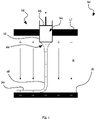
- Fig. 3 illustrates a system 10 for electro-spinning/writing of a polymer material 18, wherein the collector plate 16 can be retracted into a liquid 28 according to an example.
- the system 10 comprises a print-head 12 configured to eject the polymer material 18 via a nozzle 14, and a collector plate 16 configured for receiving the polymer material 18 ejected from the nozzle 14.
- the system 10 further comprises a vat 30 containing the liquid 28, wherein the collector plate 16 is received in the vat 30.
- the vat 30 may be an open tank with a cross-section of the vat 30 being larger than the collector plate 16 at least in a section of the vat 30, such as to receive the collector plate 16 and to enable movement of the collector plate 16 in the vat 30 over a (vertical) displacement distance to adjust a distance between the nozzle 14 and the collector plate 16.
- the vat 30 may feature a top opening to receive the polymer material 18 from the print-head 12 on the collector plate 16 as shown in Fig. 3 .
- the vat 30 may also be a substantially closed tank, and the print-head 12 may be received in a top accommodating space of the vat 30 above the collector plate 16 and/or the intended filling height of the vat 30.
- the print-head 12 may be mounted on a translation mechanism (not shown) to control a deposition of the nozzle 14 in a transverse direction with respect to the surface of the collector plate 16. By adjusting the transverse position of the nozzle 14 over time, a two-dimensional deposition pattern of the received polymer material 20 on the collector plate 16 can be controlled.
- the print-head 12 may be driven to gradually deposit multiple layers of received polymer material 20 to construct a three-dimensional polymer structure with a pre-determined shape.
- the collector plate 16 may be retracted away from the print-head 12 along the build direction to substantially maintain a constant distance between the nozzle 14 and the uppermost layer of received polymer material 20.
- the collector plate 16 can be mounted on a movable rod 32 protruding through an opening 34 in a bottom 36 of the vat 30 to be coupled to a displacement assembly (not shown).
- the displacement assembly can move the movable rod 32 through the opening 34 to change a relative position of the vat 30 and the collector plate 16.
- a distance between the print-head 12 and the collector plate 16 may be adjusted by driving a motion of the movable rod 32 via the displacement assembly, e.g. by driving an electric actuator, such as a stepper motor.
- a sealing gasket 38 may surround the movable rod 32 and may seal the bottom 36 of the vat 30 to prevent a leaking of the liquid 28 from the vat 30, while the collector plate 16 is displaced along the build direction.
- the collector plate 16 may rest in a starting position before initiating a deposition of an intended structure on the collector plate 16.
- the upper surface facing the print-head 12 may be positioned above a surface of the liquid 28, when the vat 30 is filled with the liquid 28 at a predetermined filling level, such as a predetermined filling volume.
- the vat 30 may comprise an overflow 40 at a sidewall of the vat 30, and the liquid 28 may be drained from the vat 30 through the overflow 40 above a pre-determined filling height associated with the vertical position of the overflow 40.
- the overflow 40 may define a maximum filling height for the liquid 28 in the vat 30.
- the polymer material 18 may be deposited onto the surface of the collector plate 16, e.g. until a stable jet of polymer material 18 from the nozzle 14 towards the collector plate 16 is attained.
- the system 10 may then proceed to consecutively deposit layers of received polymer material 20 corresponding to an intended shape of a part on a predetermined portion of the collector plate 16.
- the displacement mechanism may be driven to retract the collector plate 16 away from the nozzle 14, such that a distance between the nozzle 14 and collector plate 16 can be gradually increased, e.g. by retracting the collector plate 16 in accordance with a number of layers of received polymer material 20 in a stepwise manner.
- the retraction distance of the collector plate 16 may substantially correspond to a height of the layers of received polymer material 20 on the collector plate 16.
- the displacement assembly should in particular be configured to retract the collector plate 16 and at least a part of the polymer material 20 received by the collector plate 16 into the liquid 28 in the vat 30 in accordance with a height of the received polymer material 20.
- the upper surface of the collector plate 16 facing the print-head 12 may be retracted below the surface of the liquid 28, when the height of the layers of received polymer material 20 exceeds a height threshold.
- the upper surface of the collector plate 16 may rest above the liquid surface by the height threshold in the starting position and maybe immersed into the liquid 28 when the retraction distance exceeds the height threshold.
- the height threshold for immersing the collector plate 16 into the liquid 28 may be selected in accordance with a deposition height below which the deposition of the layers of received polymer material 20 is known to be stable, e.g. a deposition height below which a presence of received polymer material 20 on the collector plate 16 only negligibly distorts the intended geometry of the received polymer material 20, such as 1 mm, 2 mm or 4 mm.
- the height threshold may be empirically determined, e.g. for a utilized liquid 28 and/or a deposited polymer material 18 and/or for a structure of the print-head 12 and/or the collector 16.
- the height threshold is selected, such that the liquid 28 does not cover the surface of the collector plate 16 due to capillary and/or electrostatic forces in the starting position.
- the filling height of the liquid 28 in the vat 30 may rise while the collector plate 16 is retracted due to a displacement of the liquid 28 in the vat 30 by the retracted collector plate 16, such that the height threshold may be different from a distance between the upper surface of the collector plate 16 and the liquid surface.
- the filling height may rise up to a predetermined filling height, e.g. a predetermined filling height defined by an overflow 40.
- the vat 30 is dynamically filled with the liquid 28 before the deposition height of the received polymer material 20 exceeds the height threshold.
- Fig. 4 illustrates the system 10 of Fig. 3 , wherein the collector plate 16 has been retracted below the surface of the liquid 28 in the vat 30. Accordingly, the received polymer material 20 on the collector plate 16 is partially immersed into the liquid 28 while an upper surface of the received polymer material 20 facing the print-head 12 rests above the liquid surface.
- the liquid 28 may permeate the layers of received polymer material 20 and may cover the upper surface of the collector plate 16 facing the nozzle 14, such as to provide a substantially flat surface facing the print-head 12 close to an upper surface of the received polymer material 20.
- the liquid 28 may have a dielectric constant on the order of the dielectric constant of the received polymer material 20.
- the liquid 28 may then offset a spatially varying dielectric constant due to the presence of the received polymer material 20 and may thus at least partially offset a distortion of the flow of the polymer material 18 due to the presence of the received polymer material 20.
- the dielectric constant of the liquid 28 may also be greater or smaller than the dielectric constant of the received polymer material 20.
- the dielectric constant of the liquid 28 may be greater than the dielectric constant of the received polymer material 20 to further reduce an effect of the presence of the received polymer material 20, or may be smaller than the dielectric constant of the received polymer material 20 to limit a voltage between the nozzle 14 and the collector plate 16 or to limit an influence of the electric field onto the liquid 28.
- a jet of polymer material 18 ejected from the nozzle 14 is shown below the nozzle 14 to illustrate the intended deposition direction.
- Equipotential lines of the electric field are illustrated by solid lines while the magnitude and strength of the electric field is indicated by the size and orientation of black arrows throughout the graph.
- Fig. 5B illustrates the same polymer structure 42, but the polymer structure 42 is partially immersed into a liquid 28 having equal dielectric constant.
- the liquid 28 is polarized in the electric field in accordance with its dielectric properties, such that a bending of the electric field lines towards the polymer structure 42 is partially offset, while the electric field may be aligned substantially parallel to the upper surface of the polymer structure 42, also close to the edges of the polymer structure 42. Accordingly, the flow of the polymer material 18 can be expected to be substantially along the vertical direction, such that the deposition accuracy and/or a maximum deposition height for the polymer material 18 can be increased.
- the voltage between the print-head 12 and the collector plate 16 may be adjusted based on the distance between the collector plate 16 and the print-head 12 and/or based on an immersion depth of the collector plate 16 into the liquid 28.
- the liquid 28 may reduce the strength of the electric field between the collector plate 16 and the print-head in accordance with the dielectric constant of the liquid 28, and the voltage may be adjusted in view of the presence of the liquid 28 between the collector plate 16 and the print-head 12.
- the dielectric constant of the liquid 28 is smaller than 50 or 30 to limit a maximum voltage applied between the collector plate 16 and the print-head 12.
- the liquid 28 may also shield electric charges below the surface of the liquid 28 and may also drain electric charges from the received polymer material 20, e.g. when the liquid 28 has dissipative properties and is electrically coupled to ground, such as via the collector plate 16. Accordingly, subsequent layers of the received polymer material 20 may be deposited with a reduced influence of electrostatic distortions caused by the increasing height of the layers of the received polymer material 20.
- the collector plate 16 may also initially rest below the liquid surface.
- the polymer material 18 may be deposited onto the collector plate 16 while the collector plate 16 is covered by a thin film of the liquid 28, or may be deposited onto a vertically protruding structure previously attached on the collector plate 16, e.g. onto a previously deposited polymer structure 42, while the collector plate 16 is immersed in the liquid 28.
Landscapes
- Engineering & Computer Science (AREA)
- Chemical & Material Sciences (AREA)
- Materials Engineering (AREA)
- Manufacturing & Machinery (AREA)
- Mechanical Engineering (AREA)
- Physics & Mathematics (AREA)
- Optics & Photonics (AREA)
- Textile Engineering (AREA)
- Spinning Methods And Devices For Manufacturing Artificial Fibers (AREA)
Abstract
A system (10) for electro-spinning/writing of a polymer material (18), the system comprising a print-head (12) configured to eject the polymer material via a nozzle (14), a collector (16) configured to receive the polymer material ejected from the nozzle, a displacement assembly configured to adjust a distance between the print-head and the collector, and a vat (30) containing or configured to contain a liquid (28), wherein the vat is further configured to receive the collector, wherein the displacement assembly is configured to retract the collector and at least a part of the polymer material received by the collector into the liquid in the vat in accordance with a height of the received polymer material.
Description
- The present invention is in the field of additive manufacturing. More precisely, the present invention relates to electro-spinning/writing of polymer structures with an extended build height.
- Additive manufacturing relies on the sequential deposition of a build material to gradually build a complete part from sequentially deposited material layers based on a virtual copy of the intended structure. Usually, a relative movement between a print-head and a build plate is driven to define the geometry of one material layer in a two-dimensional plane. When subsequent layers are deposited on top of the previously deposited layers, a three-dimensional structure can be progressively constructed.
- Electro-spinning/writing is a technique wherein a flow of a polymer material from an emitter towards a collector is stabilized via an electric field. For example, a polymer may be provided in molten form by a conductive nozzle and may be directed from the nozzle onto a conductive collector plate by a high-voltage electric field, in a technique called Melt-Electro(spinning)-Writing. The electric field may charge the polymer material and pull the polymer material into streams with a thickness that is smaller than the nozzle diameter while the charged polymer material is attracted by the collector.
- The polymer stream may bridge the gap between the emitter and the collector while cooling and/or evaporating solvent material, such that a solid or solidifying polymer material is deposited on the collector. By controlling the voltage, the distance between the emitter and the collector, and the flow rate of the polymer material at the emitter, the polymer material may be deposited at a pre-defined position on the collector, or may be spun into thin fibers deposited semi-randomly in a deposition region of the collector. Three-dimensional shapes of the polymer material may then be generated by sequentially depositing multiple layers of the polymer material.
- Wunner et al. ("Melt Electrospinning Writing of Highly Ordered Large Volume Scaffold Architectures", Adv. Mater. 30 (2018) 1706570 ) disclose a Melt Electrospinning Writing (MEW) system with a spinneret and a collector plate facing each other, wherein an applied high-voltage drives the polymer melt from the spinneret onto the collector. To fabricate structures with build heights greater than 2-3 mm, the collector is dynamically distanced from the spinneret, such that the distance between the topmost layer of the deposited polymer melt and the spinneret remains constant. The voltage can be regulated at the same time, such that the electrostatic forces onto the polymer melt remain constant.
- However, the known techniques and systems are still challenged by larger build heights as the deposition accuracy particularly at larger deposition heights is often limited.
- In view of this state-of-the-art, the object of the invention is to provide an improved system for the controlled electro-spinning/writing of larger structures with an extended build height.
- This object is solved by a system for and method of electro-spinning/writing according to the independent claims. The dependent claims relate to preferred embodiments.
- According to a first aspect, the invention relates to a system for electro-spinning/writing of a polymer material. The system comprises a print-head configured to eject the polymer material via a nozzle, a collector configured to receive the polymer material ejected from the nozzle, and a displacement assembly configured to adjust a distance between the print-head and the collector. The system further comprises a vat containing or configured to contain a liquid, wherein the vat is further configured to receive the collector, and wherein the displacement assembly is configured to retract the collector and at least a part of the polymer material received by the collector into the liquid in the vat in accordance with a height of the received polymer material.
- The inventors found that the deposition accuracy and also the maximum deposition height of electro-writing/spinning may be limited due to electric interactions between the polymer jet and the deposited polymer structures. The liquid may at least partially offset/mitigate the effect of the deposited polymer structures on the electric field distribution between the nozzle and the collector. In particular, the inventors found that the presence of the deposited polymer material on the collector can bend electric field lines due to the spatially varying dielectric constant and may therefore distort the deposition pattern of subsequent polymer layers.
- The liquid in the vat may reduce a spatial variation of the relative dielectric constant and/or may provide a substantially flat potential reference plane close to the plane of deposition, such that the impact of structures protruding along the build direction onto the polymer material ejected by the nozzle can be at least partially compensated.
- The liquid may also shield and/or accept charges in/from the deposited polymer material. For example, the liquid may shield electric charges in the deposited polymer material and/or may drain electric charges from the deposited polymer material below the liquid surface.
- As a result, a more uniform electric field can be maintained between the nozzle and the uppermost layer of the deposited polymer material, and a deposition accuracy for polymer structures with structures protruding along the build height, e.g. perpendicular to the collector surface, may accordingly be increased as compared to the case where the structures are deposited in a uniform atmosphere, e.g. air, between the emitter and the collector. The system may therefore be advantageously employed for deterministic electro-writing of polymer structures, e.g. for the controlled manufacturing of implants or scaffolds for biomedical research applications with well-defined structural geometries. Further, since the liquid may shield and/or drain charges in/from the deposited polymer material, a maximum height for a manufactured polymer structure may be increased. Accordingly, the system may also be advantageously used in an electrospinning regime when depositing polymer material while applying an electric field between the nozzle and the collector.
- The polymer material may be provided to the print-head in solid or liquid form, such as a solidified polymer or a polymer mixture which can be melted in the print-head, or a polymer material which is dissolved in a solvent. For example, the polymer material may comprise polypropylene, polyethylene, polyphenylene sulfide, polyamide, polylactic acid, polyphenylene sulfide, Poly(ether-ether ketone), poly(ethylene-co-vinyl)alcohol, Poly(l-lactic acid), starch, poly(3-hydroxybutyrate), Cyclic butylene terephthalate oligomer, acetyl tributyl citrate, Polystyrene, poly(ε-caprolactone), Polylactide-poly(ethylene-glycol) Poly(vinylidene difluoride), Poly(hydroxymethyl-glycolide-co-ε-caprolactone), Poly(l-lactide-co-ε-caprolactone-co-acryloyl carbonate), Poly(urea-siloxane)s, or a mixture thereof, and may comprise functional additives, such as bioactive glass particles, reduced tungsten oxide, or hydroxyapatite, e.g. for the use in implants or artificial scaffolds for biomedical applications. However, the skilled person will appreciate that these substances are merely examples and the system and associated method can be generally used for a deposition of polymer fibers with most polymers having sufficient molecular entanglements to not break up into droplets due to Raleigh instabilities during a transfer between the nozzle and the collector. In addition, the system and disclosed techniques may also be advantageously employed for electro-spraying techniques, wherein a sequence of charged polymer droplets is directed from the print-head towards the collector.
- In preferred embodiments, the system comprises a heater configured to melt polymer material to form a polymer melt to be ejected through the nozzle.
- A polymer melt can have a higher viscosity than a polymer solution and may solidify over a shorter collector distance, such as a distance smaller than 10 mm, in particular a distance smaller than 8 mm, such as about 4 mm, between the collector and the nozzle, which may increase a control over the deposition location of the polymer material. Further, polymer melts may retain fewer charges than polymer solutions which may result in increased deposition accuracy and/or a maximum deposition height of the polymer material deposited in multiple layers. The polymer material may be fed to the nozzle in the form of filaments or granulates and may be heated in the print-head to form the polymer melt.
- The polymer material may exit the print-head in at least partially liquid form and may be subjected to an electric field applied between a conductive nozzle and a conductive collector facing the print-head. The polymer material may be charged in the electric field at the nozzle and may be pulled towards the collector in the electric field. In some embodiments, the polymer material forms a continuous fluid column extending between the nozzle and the collector, while the polymer stream may taper from the nozzle towards the collector, e.g. form a Taylor cone at the nozzle and taper towards the collector. The polymer material may then be jetted from the tip of the Taylor cone towards the collector to form polymer fibers on the collector.
- In preferred embodiments, a voltage is applied between the collector and the print-head, wherein the voltage is suitable for controlling a flow of polymer material from the print-head towards the collector.
- The electric potential may be selected such that a stable fluid column is formed between the nozzle and the collector, wherein a flow of the polymer material may be substantially along the electrical field lines. For example, the electric potential may be larger than 100 V, in particular larger than 1 kV, e.g. between 1 kV and 100 kV, to stabilize a stream of the polymer material ejected from the nozzle and/or to direct the polymer material from the nozzle towards the collector.
- In preferred embodiments, the system further comprises a voltage source configured to apply a selectable electric potential to the print-head and/or the collector.
- The voltage source may apply electric potentials of opposite polarities to the nozzle and the collector or may apply a selectable electric potential to one of the nozzle and the collector while the other one of the nozzle and the collector is (electrically) grounded.
- In preferred embodiments, the collector is (electrically) grounded, and the nozzle is configured to be held at a selectable electric potential, wherein the selectable electric potential is suitable for controlling a flow of polymer material from the print-head towards the collector.
- When the collector is immersed into the liquid in the vat, an electric field at the nozzle induced by a charged collector may be partially compensated by a polarization of the liquid and may thus vary based on the immersion depth. By applying the electric potential to the nozzle while the collector is (electrically) grounded, the electric field strength acting on the polymer material ejected from the nozzle may be directly controlled by the electric potential. Further, applying the electric potential at the nozzle may simplify electrical insulation of the system as opposed to applying an electric potential to the at least partially immersed collector.
- The polymer material ejected from the nozzle may be deposited in the form of polymer fibers while the print-head and the collector perform a relative movement in a two-dimensional plane. Preferably, the collector is held in the vat while the print-head moves in a two-dimensional plane to define the geometry of a two-dimensional layer of polymer fibers deposited onto the collector. The print-head may continuously deposit polymer fibers onto the collector to progressively deposit multiple layers of polymer fibers. However, in some embodiments, the system may be configured to deposit polymer droplets, e.g. in an electro-spraying mode of the print-head.
- The displacement assembly can be configured to move the collector away from the nozzle in accordance with a height of the deposited polymer material. In some embodiments, the displacement assembly is configured to retract the collector away from the nozzle based on an elapsed time of depositing polymer material on the collector, wherein the collector may be retracted stepwise or continuously. Further, the displacement assembly may be configured to retract the collector away from the nozzle based on a deposition height. The deposition height may be estimated from an intended structure deposited by the print-head, or may be measured based on a height of a polymer structure received on the collector. Preferably, the displacement assembly is configured to retract the collector away from the nozzle after a predetermined estimated layer height has been deposited by the print-head, such as after each layer or after a predetermined number of layers deposited by the print-head onto the collector.
- The movement of the displacement assembly may be controlled by a control system which may send control signals to an actuator of the displacement assembly. The control system may comprise a single control unit or may comprise a plurality of control units which may be functionally connected. The control units may comprise a microcontroller, an ASIC, a PLA (CPLA), an FPGA, or other control device, including control devices operating based on software, hardware, firmware, or a combination thereof. The control devices can include an integrated memory, or communicate with an external memory, or both, and may further comprise interfaces for connecting to sensors, devices, appliances, integrated logic circuits, other controllers, or the like, wherein the interfaces may be configured to receive or send signals, such as electrical signals, optical signals, wireless signals, acoustic signals, or the like.
- A virtual replica of the three-dimensional geometry of an intended polymer structure may be provided in a memory of the control system or an external computing system and may comprise or be translated into control instructions for the displacement assembly to drive a motion of the print-head and/or the collector. The control system may then drive the displacement assembly in accordance with the control instructions for manufacturing the intended polymer structure and/or based on received signals, e.g. sensor readings.
- In preferred embodiments, the system comprises a control system configured to control the displacement assembly such as to retract the collector further into the vat while the height of the received polymer material increases, wherein a retraction distance of the collector into the vat is in particular proportional to the height of the received polymer material.
- The collector may rest at or close to a surface of the liquid in the vat at an initial stage of depositing the polymer material on the collector and may be retracted into the liquid in the vat during the deposition of the polymer material on the collector. Preferably, the retraction distance corresponds to the deposition height of the polymer on the collector, which may be estimated based on the deposition history of the polymer material. The skilled person will appreciate that the collector may be held at a constant (vertical) position during an initial deposition of the polymer material and may only be moved via the displacement assembly after a predetermined elapsed time and/or a predetermined height of the polymer material deposited on the collector. Further, the skilled person will appreciate that the movement of the collector may be driven in a stepwise manner, such that the retraction distance may only on average be proportional or correspond to the height of the received polymer material.
- In preferred embodiments, the control system is configured to control the displacement assembly to immerse the collector into the liquid when the deposition height exceeds a height threshold.
- For example, the collector may initially rest above the surface of the liquid in the vat to form layers of polymer material on the surface of the collector, and may be retracted into the liquid, such that the collector surface facing the print-head is immersed into the liquid, when the estimated or measured deposition height exceeds the height threshold, e.g. 10 µm, 100 µm, 1 mm, or 2 mm. In some embodiments, the collector rests above the surface of the liquid in the vat by the height threshold and is progressively retracted into the vat in accordance with the deposition height, such that the collector surface facing the print-head is immersed into the liquid, when the deposition height exceeds the height threshold.
- The displacement assembly for adjusting a relative position of the collector along the build height may be arranged in the vat or may be partially arranged outside the vat to drive a movement of the collector and to immerse the collector in the liquid in accordance with the deposition height.
- In preferred embodiments, the collector comprises a collector plate facing the print-head and a movable support protruding through an opening in a bottom of the vat, wherein the displacement assembly is configured to move the movable support through the opening to adjust a relative position of the collector / collector plate with respect to the print-head.
- The opening may comprise a gasket to seal the bottom of the vat while the movable support is pulled through the opening. For example, the movable support may be a cylindrical rod protruding through a circular opening in the bottom of the vat, wherein the circular opening may comprise a sealing gasket around its rim to prevent the liquid from escaping from the vat through the opening while the movable support is moved through the opening. The displacement assembly may then drive a motion of the collector plate by displacing the movable support with respect to the vat.
- The vat may be a tank with an open top for holding the liquid. In operation, the vat may hold the liquid at a predetermined filling level, such as a predetermined liquid volume or predetermined filling height. For example, the collector and the vat may be configured, such that a rise of the filling height while immersing the collector in the liquid is smaller than 2 mm or smaller than 1 mm, such as to only negligibly affect a deposition of the polymer material.
- In preferred embodiments, the vat comprises a level control unit, in particular an overflow, for maintaining a constant filling height of the vat holding the liquid while the collector is retracted into the vat.
- The constant filling height may substantially correspond to a target deposition distance between the print-head and the uppermost layer of the polymer material, such that the level control unit may prevent the liquid from reducing the target deposition distance while the liquid is displaced by the retracting collector. The skilled person will appreciate that the uppermost layer of the polymer material may lie above the surface of the liquid, such that the distance between the liquid surface and the nozzle may generally be larger than the target deposition distance, e.g. by a critical deposition height, such as 1 mm or 2 mm. By using an overflow as the level control unit, the filling height may be passively controlled with simple technical means. The overflow may also simplify filling the vat up to the predetermined filling level. In some embodiments, the liquid rises up to the constant filling height while the collector retracts away from the nozzle, e.g. due to a displacement of the liquid by the collector.
- In preferred embodiments, the liquid is a dielectric medium, wherein a dielectric constant of the dielectric medium is in particular smaller than 50, preferably smaller than 30.
- The polymer may have a dielectric constant which may be an order of magnitude larger than the dielectric constant of air and may accordingly bend the electric field lines in its vicinity. The path of the polymer material ejected from the nozzle may accordingly be distorted in the vicinity of polymer material received previously by the collector. The dielectric medium may equalize a dielectric constant below the surface of the dielectric medium. As the polymer material deposited by electro-spinning/writing can be porous, the dielectric medium can permeate the received polymer material on the collector for providing a substantially flat surface close to the uppermost polymer layers with a constant dielectric constant, such as to reduce an impact of the presence of the deposited polymer material onto subsequently received polymer materials. The dielectric medium may also shield charges of the deposited polymer material and thereby further increase a deposition accuracy of the system.
- The dielectric medium may have a dielectric constant which is larger than the dielectric constant of air or the polymer material and may be smaller than 50 to reduce an effect of the liquid onto the electric field strength experienced by the polymer material ejected from the nozzle. For example, the liquid may be demineralized water, ethanol, isopropanol, methanol, phenol, chloroform, or oils. Preferably, the liquid has disinfecting properties for disinfecting the polymer material received on the collector plate.
- In preferred embodiments, the liquid is (electrically) conductive and the vat and/or the collector is (electrically) grounded to maintain a constant electric potential of the liquid.
- The conductive liquid may be at least dissipative to maintain a ground potential of the liquid. For example, a resistivity of the liquid may be smaller than 109Ωm or smaller than 108Ωm. The dissipative properties of the liquid may drain or shield charges from/in the received polymer material on the collector and may also allow providing a constant electric potential at the surface of the liquid. In some embodiments, the conductivity of the liquid is high, such as smaller than 106Ωm or smaller than 105Ωm, such that the liquid surface may act as a counter electrode for the electro-spinning/writing process.
- The skilled person will appreciate that the liquid may have both dielectric and conductive properties. For example, demineralized water can be dissipative to drain charges from the polymer while also acting as a dielectric medium to at least partially offset an increased dielectric constant of the received polymer material on the collector for the electro-spinning/writing process. In some embodiments, the resistivity of the liquid is between 109Ωm and 105Ωm or between 108Ωm and 106Ωm.
- According to a second aspect, the invention relates to a method for electro-spinning/writing of a polymer material. The method comprises providing the polymer material at a print-head, applying a voltage between the print-head and a collector facing the print-head, and initiating a stream of the polymer material from the print-head towards the collector. The method further comprises retracting the collector away from the print-head into a liquid along with an increase of a deposition height of the polymer material on the collector.
- In some embodiments, one of the collector and the print-head is (electrically) grounded while a selectable electric potential is applied to the other one of the collector and the print-head for controlling a flow of polymer material from the nozzle towards the collector.
- In preferred embodiments, the method further comprises (electrically) grounding the collector, and applying a selectable electric potential to a nozzle of the print-head for controlling a flow of polymer material from the nozzle towards the collector.
- In preferred embodiments, the method further comprises maintaining a constant filling height of a vat holding the liquid while the collector is retracted into the vat.
- In preferred embodiments, the collector comprises a collector plate facing the print-head and a movable support protruding through an opening in a bottom of the vat, and wherein the method further comprises retracting the movable support through the opening to adjust a relative position of the collector / collector plate with respect to the print-head.
- In preferred embodiments, the method comprises immersing the collector into the liquid when the deposition height exceeds a height threshold.
- In preferred embodiments, the liquid is a dielectric medium, wherein a dielectric constant of the dielectric medium is in particular smaller than 50, preferably smaller than 30.
- In preferred embodiments, the liquid is conductive and the vat and/or the collector is (electrically) grounded to maintain a constant electric potential of the liquid.
- According to a third aspect, the invention relates to a computer program or computer program product comprising machine readable instructions, which when executed on a control system implement a method according to the second aspect or drive a system according to the first aspect.
- The features and numerous advantages of the system and corresponding method according to the present invention will best be understood from a detailed description of preferred embodiments with reference to the accompanying drawings, in which:
- Fig. 1
- schematically illustrates an example of an electro-spinning/writing system;
- Fig. 2
- schematically illustrates an example of a method for electro-spinning/writing of polymer structures extending along the build direction;
- Fig. 3
- illustrates a system for electro-spinning/writing of a polymer material, wherein the collector plate can be retracted into a liquid according to an example;
- Fig. 4
- illustrates the system of
Fig. 3 , wherein the collector plate has been retracted below the surface of the liquid in the vat; and - Fig. 5A, 5B
- show examples of electrostatic simulations for a solid polymer structure on a collector plate facing a charged nozzle without and with a liquid of equal relative dielectric constant, respectively.
-
Fig. 1 schematically illustrates an electro-spinning/writing system 10 according to an example. The electro-spinning/writing system 10 comprises a print-head 12 with aconductive nozzle 14 arranged above aconductive collector plate 16. A voltage can be applied between the print-head 12 and the collector plate 16 (as illustrated by exemplary charges +/at the print-head 12 and the conductive collector plate 16) via anelectrode 17 and may induce an electric field (schematically illustrated by straight arrows "E") bridging the gap between the print-head 12 and thecollector plate 16. A stream ofpolymer material 18 maybe ejected from thenozzle 14 towards thecollector plate 16 to form a layer of receivedpolymer material 20 on thecollector plate 16. - The print-
head 12 and thecollector plate 16 may be moved relative to each other in a transverse plane, such that the stream ofpolymer material 18 may be deposited as a polymer fiber on thecollector plate 16, wherein the extension of the polymer fiber may substantially follow a direction of relative movement between the print-head 12 and thecollector plate 16 in an electro-writing mode of thesystem 10. In an electro-spinning mode of thesystem 10, the fibers may be electrospun onto a predetermined deposition region, such that the orientation of the deposited polymer fibers may also be randomized in embodiments. - To drive a relative motion in the transverse plane and to define the geometry of the deposited polymer structure, the print-
head 12 and/or thecollector plate 16 may be coupled to a translation stage to drive a relative motion of the print-head 12 and thecollector plate 16 in the transverse plane. For example, the print-head 12 may be mounted to a carriage (not shown) to be translated with respect to thecollector plate 16 in a transverse direction, e.g. along perpendicular X/Y axes extending substantially parallel to the surface of thecollector plate 16. - The
polymer material 18 may be a dissolved polymer in a solvent or may be a polymer melt obtainable by heating apolymer base material 24, such as solid polymer granulates or polymer filaments, beyond its melting point. For example, polymer granulates may be heated in the print-head 12 and extruded through thenozzle 14, such as by pressuring the polymer melt with apiston 26, e.g. with pressurized air, for forcing the polymer melt through the nozzle aperture, as illustrated inFig. 1 . In some embodiments, thepolymer base material 24 may be provided as a filament which is fed into the print-head 12 to be heated in the print-head 12 and extruded through thenozzle 14, e.g. while being pushed by the solid polymer filament (not shown). - The at least partially
liquid polymer material 18 may be charged in the nozzle 14 (as schematically illustrated by positive charges in the polymer stream) and may be pulled from thenozzle 14 towards thecollector plate 16. The electric forces acting on thepolymer material 18 may induce a tapering 22 of thepolymer material 18 at thenozzle 14. The tapering 22 may form an approximated Taylor cone from which a jet of chargedpolymer material 18 may be ejected towards thecollector plate 16. As thepolymer material 18 tapers away from thenozzle 14, a stream of thepolymer material 18 between thenozzle 14 and thecollector plate 16 may feature a smaller diameter than the diameter of thenozzle 14 and may be deposited as a polymer fiber in the layer ofpolymer material 20. For example, thepolymer material 18 may be deposited as polymer fibers featuring a thickness of less than 100 µm, e.g. between 0.2 µm and 100 µm or between 5 µm and 50 µm, while the nozzle diameter may be between 0.1 mm and 0.4 mm. - The
polymer material 18 may solidify during the passage between thenozzle 14 and thecollector 16 by cooling and/or evaporation of solvent constituents, such that a viscosity of thepolymer material 18 may increase towards thecollector plate 16. Solidifying or solid polymer fibers may then be deposited on thecollector plate 16 or on previously received layers ofpolymer material 20. - The
system 10 may gradually deposit a plurality of layers ofpolymer material 20 on top of each other, wherein the geometry of each layer ofpolymer material 20 may differ to construct a three-dimensional shape from a plurality of essentially two-dimensional slices/layers. Depending on the distance and voltage between thenozzle 14 and thecollector 16, the polymer fibers may be deposited at predetermined locations or deposition regions, to generate a deterministic geometry of receivedpolymer material 20 on thecollector 16. For example, a distance between thenozzle 14 and thecollector 16 or the uppermost layer of receivedpolymer material 20 may be between about 1.5 mm to about 10 mm, e.g. between about 2.5 mm and about 8 mm, to enable electro-writing with thepolymer material 18. - In accordance with an increasing deposition height of the layers of
polymer material 20 on thecollector plate 16, a distance between the print-head 12 and thecollector 16 may be adjusted, such that a distance between thenozzle 14 and the uppermost layer ofpolymer material 20 remains substantially constant. A substantially constant distance between thecollector plate 16 and the uppermost layer ofpolymer material 20 may avoid proximity effects of thenozzle 14 onto the deposited layers ofpolymer materials 20, such as melting of previously deposited fibers, attraction ofpolymer material nozzle 14, or distortion of the Taylor cone. - The voltage applied between the
nozzle 14 and thecollector plate 16 may be increased in accordance with the varying spacing between thecollector plate 16 and thenozzle 14, such as to maintain a substantially constant electrical field at thenozzle 14 for inducing the tapering 22 and for controlling the flow ofpolymer material 18 from thenozzle 14 towards thecollector plate 16. For example, a voltage of about 5 kV may be applied between thenozzle 14 and thecollector plate 16 at a distance between thenozzle 14 and thecollector plate 16 of about 3 mm, such as to deposit a solidifying polymer fiber in a predetermined location onto thecollector plate 16, and the voltage may be increased in accordance with an increasing distance between thecollector plate 16 and thenozzle 14. - In some embodiments, the distance between the
nozzle 14 and thecollector plate 16 may be larger than a critical distance for an Ohmic flow regime (electro-writing regime) of thepolymer material 18, such that thepolymer material 18 may be electrospun onto thecollector plate 16 and previously receivedpolymer material 20 in a convective flow regime, such as to deposit electrospun fibers in a predetermined deposition region. - Hence, three-dimensional shapes of the
polymer material polymer material 20. However, the layers of receivedpolymer material 20 may locally influence the electric field distribution between thenozzle 14 and thecollector plate 16 by their dielectric properties or by charges retained in the layers of receivedpolymer material 20, such that a deposition accuracy may progressively reduce with increasing deposition height. Depending on the utilizedpolymer material 18 during deposition, charging effects of thepolymer material polymer material 20 above a certain critical deposition height. -
Fig. 2 schematically illustrates a method for electro-spinning/writing of apolymer material 18 according to an example. The method comprises providing thepolymer material head 12 and acollector 16 facing the print-head 12 (S12), and initiating a stream of thepolymer material 18 from the print-head 12 towards the collector 16 (S14). The method further comprises retracting thecollector 16 away from the print-head 12 into a liquid along with an increase of a deposition height of thepolymer material 20 on the collector 16 (S16). - In the method of
Fig. 2 , the influence of the layers of receivedpolymer material 20 may be at least partially mitigated by immersing thecollector 16 and at least a part of thepolymer material 20 received by thecollector 16 in a liquid. The liquid may offset electrostatic effects of the deposited layers of adielectric polymer material 20 due to a polarization of the liquid in the electric field, and may shield electric charges retained in the polymer material. In addition, the liquid may drain electric charges from the polymer material, and may in some embodiments present a substantially flat ground potential reference at the liquid surface. Accordingly, the critical deposition height for layers of receivedpolymer material 20 may be increased. -
Fig. 3 illustrates asystem 10 for electro-spinning/writing of apolymer material 18, wherein thecollector plate 16 can be retracted into a liquid 28 according to an example. Thesystem 10 comprises a print-head 12 configured to eject thepolymer material 18 via anozzle 14, and acollector plate 16 configured for receiving thepolymer material 18 ejected from thenozzle 14. Thesystem 10 further comprises avat 30 containing the liquid 28, wherein thecollector plate 16 is received in thevat 30. - The
vat 30 may be an open tank with a cross-section of thevat 30 being larger than thecollector plate 16 at least in a section of thevat 30, such as to receive thecollector plate 16 and to enable movement of thecollector plate 16 in thevat 30 over a (vertical) displacement distance to adjust a distance between thenozzle 14 and thecollector plate 16. Thevat 30 may feature a top opening to receive thepolymer material 18 from the print-head 12 on thecollector plate 16 as shown inFig. 3 . However, thevat 30 may also be a substantially closed tank, and the print-head 12 may be received in a top accommodating space of thevat 30 above thecollector plate 16 and/or the intended filling height of thevat 30. - The print-
head 12 may be mounted on a translation mechanism (not shown) to control a deposition of thenozzle 14 in a transverse direction with respect to the surface of thecollector plate 16. By adjusting the transverse position of thenozzle 14 over time, a two-dimensional deposition pattern of the receivedpolymer material 20 on thecollector plate 16 can be controlled. - The print-
head 12 may be driven to gradually deposit multiple layers of receivedpolymer material 20 to construct a three-dimensional polymer structure with a pre-determined shape. In accordance with an increasing deposition height of the receivedpolymer material 20, thecollector plate 16 may be retracted away from the print-head 12 along the build direction to substantially maintain a constant distance between thenozzle 14 and the uppermost layer of receivedpolymer material 20. - To displace the
collector plate 16, thecollector plate 16 can be mounted on amovable rod 32 protruding through anopening 34 in a bottom 36 of thevat 30 to be coupled to a displacement assembly (not shown). The displacement assembly can move themovable rod 32 through theopening 34 to change a relative position of thevat 30 and thecollector plate 16. Hence, a distance between the print-head 12 and thecollector plate 16 may be adjusted by driving a motion of themovable rod 32 via the displacement assembly, e.g. by driving an electric actuator, such as a stepper motor. - A sealing
gasket 38 may surround themovable rod 32 and may seal the bottom 36 of thevat 30 to prevent a leaking of the liquid 28 from thevat 30, while thecollector plate 16 is displaced along the build direction. - The
collector plate 16 may rest in a starting position before initiating a deposition of an intended structure on thecollector plate 16. In the starting position, the upper surface facing the print-head 12 may be positioned above a surface of the liquid 28, when thevat 30 is filled with the liquid 28 at a predetermined filling level, such as a predetermined filling volume. - As illustrated in
Fig. 3 , thevat 30 may comprise anoverflow 40 at a sidewall of thevat 30, and the liquid 28 may be drained from thevat 30 through theoverflow 40 above a pre-determined filling height associated with the vertical position of theoverflow 40. In other words, theoverflow 40 may define a maximum filling height for the liquid 28 in thevat 30. - In the starting position, the
polymer material 18 may be deposited onto the surface of thecollector plate 16, e.g. until a stable jet ofpolymer material 18 from thenozzle 14 towards thecollector plate 16 is attained. Thesystem 10 may then proceed to consecutively deposit layers of receivedpolymer material 20 corresponding to an intended shape of a part on a predetermined portion of thecollector plate 16. - While the layers of received
polymer material 20 are deposited on thecollector plate 16, the displacement mechanism may be driven to retract thecollector plate 16 away from thenozzle 14, such that a distance between thenozzle 14 andcollector plate 16 can be gradually increased, e.g. by retracting thecollector plate 16 in accordance with a number of layers of receivedpolymer material 20 in a stepwise manner. The retraction distance of thecollector plate 16 may substantially correspond to a height of the layers of receivedpolymer material 20 on thecollector plate 16. - The displacement assembly should in particular be configured to retract the
collector plate 16 and at least a part of thepolymer material 20 received by thecollector plate 16 into the liquid 28 in thevat 30 in accordance with a height of the receivedpolymer material 20. - The upper surface of the
collector plate 16 facing the print-head 12 may be retracted below the surface of the liquid 28, when the height of the layers of receivedpolymer material 20 exceeds a height threshold. For example, the upper surface of thecollector plate 16 may rest above the liquid surface by the height threshold in the starting position and maybe immersed into the liquid 28 when the retraction distance exceeds the height threshold. - The height threshold for immersing the
collector plate 16 into the liquid 28 may be selected in accordance with a deposition height below which the deposition of the layers of receivedpolymer material 20 is known to be stable, e.g. a deposition height below which a presence of receivedpolymer material 20 on thecollector plate 16 only negligibly distorts the intended geometry of the receivedpolymer material 20, such as 1 mm, 2 mm or 4 mm. The height threshold may be empirically determined, e.g. for a utilizedliquid 28 and/or a depositedpolymer material 18 and/or for a structure of the print-head 12 and/or thecollector 16. - In some embodiments, the height threshold is selected, such that the liquid 28 does not cover the surface of the
collector plate 16 due to capillary and/or electrostatic forces in the starting position. - In some embodiments, the filling height of the liquid 28 in the
vat 30 may rise while thecollector plate 16 is retracted due to a displacement of the liquid 28 in thevat 30 by the retractedcollector plate 16, such that the height threshold may be different from a distance between the upper surface of thecollector plate 16 and the liquid surface. The filling height may rise up to a predetermined filling height, e.g. a predetermined filling height defined by anoverflow 40. In some embodiments, thevat 30 is dynamically filled with the liquid 28 before the deposition height of the receivedpolymer material 20 exceeds the height threshold. - When the
collector plate 16 is immersed into the liquid 28, an influence of the presence of receivedpolymer material 20 on the deposition location ofadditional polymer material 18 due to electrostatic forces may be at least partially offset by the liquid 28. -
Fig. 4 illustrates thesystem 10 ofFig. 3 , wherein thecollector plate 16 has been retracted below the surface of the liquid 28 in thevat 30. Accordingly, the receivedpolymer material 20 on thecollector plate 16 is partially immersed into the liquid 28 while an upper surface of the receivedpolymer material 20 facing the print-head 12 rests above the liquid surface. The liquid 28 may permeate the layers of receivedpolymer material 20 and may cover the upper surface of thecollector plate 16 facing thenozzle 14, such as to provide a substantially flat surface facing the print-head 12 close to an upper surface of the receivedpolymer material 20. - The liquid 28 may have a dielectric constant on the order of the dielectric constant of the received
polymer material 20. The liquid 28 may then offset a spatially varying dielectric constant due to the presence of the receivedpolymer material 20 and may thus at least partially offset a distortion of the flow of thepolymer material 18 due to the presence of the receivedpolymer material 20. However, the dielectric constant of the liquid 28 may also be greater or smaller than the dielectric constant of the receivedpolymer material 20. For example, the dielectric constant of the liquid 28 may be greater than the dielectric constant of the receivedpolymer material 20 to further reduce an effect of the presence of the receivedpolymer material 20, or may be smaller than the dielectric constant of the receivedpolymer material 20 to limit a voltage between thenozzle 14 and thecollector plate 16 or to limit an influence of the electric field onto the liquid 28. -
Fig. 5A, 5B show examples of electrostatic simulations for asolid polymer structure 42 on acollector plate 16 facing a chargednozzle 14 without and with a liquid 28 of equal relative dielectric constant (εr = 6), respectively. A jet ofpolymer material 18 ejected from thenozzle 14 is shown below thenozzle 14 to illustrate the intended deposition direction. Equipotential lines of the electric field are illustrated by solid lines while the magnitude and strength of the electric field is indicated by the size and orientation of black arrows throughout the graph. - In
Fig. 5A , no liquid 28 is present and the electric field bends in the proximity of thepolymer structure 42 in the direction of thepolymer structure 42 due to a polarization of thepolymer structure 42 in the electric field. Hence, whenadditional polymer material 18 is deposited onto thepolymer structure 42, thepolymer material 18 may be pulled along the electric field lines towards thepolymer structure 42. -
Fig. 5B illustrates thesame polymer structure 42, but thepolymer structure 42 is partially immersed into a liquid 28 having equal dielectric constant. The liquid 28 is polarized in the electric field in accordance with its dielectric properties, such that a bending of the electric field lines towards thepolymer structure 42 is partially offset, while the electric field may be aligned substantially parallel to the upper surface of thepolymer structure 42, also close to the edges of thepolymer structure 42. Accordingly, the flow of thepolymer material 18 can be expected to be substantially along the vertical direction, such that the deposition accuracy and/or a maximum deposition height for thepolymer material 18 can be increased. - Referring again to
Fig. 4 , the voltage between the print-head 12 and thecollector plate 16 may be adjusted based on the distance between thecollector plate 16 and the print-head 12 and/or based on an immersion depth of thecollector plate 16 into the liquid 28. For example, the liquid 28 may reduce the strength of the electric field between thecollector plate 16 and the print-head in accordance with the dielectric constant of the liquid 28, and the voltage may be adjusted in view of the presence of the liquid 28 between thecollector plate 16 and the print-head 12. Preferably, the dielectric constant of the liquid 28 is smaller than 50 or 30 to limit a maximum voltage applied between thecollector plate 16 and the print-head 12. - The liquid 28 may also shield electric charges below the surface of the liquid 28 and may also drain electric charges from the received
polymer material 20, e.g. when the liquid 28 has dissipative properties and is electrically coupled to ground, such as via thecollector plate 16. Accordingly, subsequent layers of the receivedpolymer material 20 may be deposited with a reduced influence of electrostatic distortions caused by the increasing height of the layers of the receivedpolymer material 20. - While the preceding examples have focused on a deposition of the
polymer material 18 onto acollector plate 16 in a starting position above the liquid surface, the skilled person will appreciate that thecollector plate 16 may also initially rest below the liquid surface. For example, thepolymer material 18 may be deposited onto thecollector plate 16 while thecollector plate 16 is covered by a thin film of the liquid 28, or may be deposited onto a vertically protruding structure previously attached on thecollector plate 16, e.g. onto a previously depositedpolymer structure 42, while thecollector plate 16 is immersed in the liquid 28. - The description of the preferred embodiments and the figures merely serve to illustrate the invention and the beneficial effects associated therewith, but should not be understood to imply any limitation. The scope of the invention is to be determined solely by the appended claims.
-
- 10
- system
- 12
- print-head
- 14
- nozzle
- 16
- collector (plate)
- 18
- polymer material
- 20
- received polymer material
- 22
- tapering/Taylor cone
- 24
- polymer base material
- 26
- piston
- 28
- liquid
- 30
- vat
- 32
- movable rod
- 34
- opening
- 36
- bottom of the vat
- 38
- sealing gasket
- 40
- overflow
- 42
- polymer structure
Claims (15)
- A system (10) for electro-spinning/writing of a polymer material (18), the system (10) comprising:a print-head (12) configured to eject the polymer material (18) via a nozzle (14);a collector (16) configured to receive the polymer material (18) ejected from the nozzle (14);a displacement assembly configured to adjust a distance between the print-head (12) and the collector (16); anda vat (30) containing or configured to contain a liquid (28), wherein the vat (30) is further configured to receive the collector (16); andwherein the displacement assembly is configured to retract the collector (16) and at least a part of the polymer material (20) received by the collector (16) into the liquid (28) in the vat (30) in accordance with a height of the received polymer material (20).
- The system (10) of claim 1, wherein the system (10) further comprises a heater configured to melt polymer material (24) to form a polymer melt to be ejected through the nozzle (14).
- The system (10) of claim 1 or 2, wherein a voltage is applied between the collector (16) and the print-head (12), wherein the voltage is suitable for controlling a flow of polymer material (18) from the print-head (12) towards the collector (16); and/or
wherein the system (10) further comprises a voltage source configured to apply a selectable electric potential to the print-head (12) and/or the collector (16); and/or wherein the collector (16) is grounded, and wherein the nozzle (14) is configured to be held at a selectable electric potential, wherein the selectable electric potential is suitable for controlling a flow of polymer material (18) from the print-head (12) towards the collector (16). - The system (10) of any one of the preceding claims, wherein the system (10) further comprises a control system configured to control the displacement assembly such as to retract the collector (16) further into the vat (30) while the height of the received polymer material (20) increases, wherein a retraction distance of the collector (16) into the vat (30) is in particular proportional to the height of the received polymer material (20),wherein the control system is preferably configured to control the displacement assembly to immerse the collector (16) into the liquid (28) when the deposition height exceeds a height threshold.
- The system (10) of any one of the preceding claims, wherein the collector (16) comprises a collector plate (16) facing the print-head (12) and a movable support (32) protruding through an opening (34) in a bottom (36) of the vat (30), wherein the displacement assembly is configured to move the movable support (32) through the opening (34) to adjust a relative position of the collector (16) with respect to the print-head (12).
- The system (10) of any one of the preceding claims, wherein the vat (30) comprises a level control unit, in particular an overflow (40), for maintaining a constant filling height of the vat (30) holding the liquid (28) while the collector (16) is retracted into the vat (30).
- The system (10) of any one of the preceding claims, wherein the liquid (28) is a dielectric medium, wherein a dielectric constant of the dielectric medium is in particular smaller than 50, preferably smaller than 30.
- The system (10) of any one of the preceding claims, wherein the liquid (28) is conductive and the vat (30) and/or the collector (16) is grounded to maintain a constant electric potential of the liquid (28).
- Method for electro-spinning/writing of a polymer material (18), the method comprising:providing the polymer material (18) at a print-head (12);applying a voltage between the print-head (12) and a collector (16) facing the print-head (12);initiating a stream of the polymer material (18) from the print-head (12) towards the collector (16); andretracting the collector (16) away from the print-head (12) into a liquid (28) along with an increase of a deposition height of the polymer material (20) on the collector (16).
- The method of claim 9, further comprising
grounding the collector (16); and
applying a selectable electric potential to a nozzle (14) of the print-head (12) for controlling a flow of polymer material (18) from the nozzle (14) towards the collector (16). - The method of claim 9 or 10, further comprising
maintaining a constant filling height of a vat (30) holding the liquid (28) while the collector (16) is retracted into the vat (30). - The method of any one of claims 9 to 11, wherein the collector (16) comprises a collector plate (16) facing the print-head (12) and a movable support (32) protruding through an opening (34) in a bottom (36) of the vat (30), and wherein the method further comprises retracting the movable support (32) through the opening (34) to adjust a relative position of the collector (16) with respect to the print-head (12).
- The method of any one of claims 9 to 12, wherein the method comprises immersing the collector (16) into the liquid (28) when the deposition height exceeds a height threshold.
- The method of any one of claims 9 to 13, wherein the liquid (28) is a dielectric medium, wherein a dielectric constant of the dielectric medium is in particular smaller than 50, preferably smaller than 30.
- The method of any one of claims 9 to 14, wherein the liquid (28) is conductive and the vat (30) and/or the collector (16) is grounded to maintain a constant electric potential of the liquid (28).
Priority Applications (5)
| Application Number | Priority Date | Filing Date | Title |
|---|---|---|---|
| EP20211278.5A EP4008522A1 (en) | 2020-12-02 | 2020-12-02 | Electro-spinning/writing system and corresponding method |
| US18/254,199 US20240001606A1 (en) | 2020-12-02 | 2021-12-01 | Electro-spinning/writing system and corresponding method |
| PCT/EP2021/083812 WO2022117667A1 (en) | 2020-12-02 | 2021-12-01 | Electro-spinning/writing system and corresponding method |
| EP21835176.5A EP4204209A1 (en) | 2020-12-02 | 2021-12-01 | Electro-spinning/writing system and corresponding method |
| JP2023527812A JP2023551788A (en) | 2020-12-02 | 2021-12-01 | Electrospinning/writing system and corresponding method |
Applications Claiming Priority (1)
| Application Number | Priority Date | Filing Date | Title |
|---|---|---|---|
| EP20211278.5A EP4008522A1 (en) | 2020-12-02 | 2020-12-02 | Electro-spinning/writing system and corresponding method |
Publications (1)
| Publication Number | Publication Date |
|---|---|
| EP4008522A1 true EP4008522A1 (en) | 2022-06-08 |
Family
ID=73694868
Family Applications (2)
| Application Number | Title | Priority Date | Filing Date |
|---|---|---|---|
| EP20211278.5A Withdrawn EP4008522A1 (en) | 2020-12-02 | 2020-12-02 | Electro-spinning/writing system and corresponding method |
| EP21835176.5A Pending EP4204209A1 (en) | 2020-12-02 | 2021-12-01 | Electro-spinning/writing system and corresponding method |
Family Applications After (1)
| Application Number | Title | Priority Date | Filing Date |
|---|---|---|---|
| EP21835176.5A Pending EP4204209A1 (en) | 2020-12-02 | 2021-12-01 | Electro-spinning/writing system and corresponding method |
Country Status (4)
| Country | Link |
|---|---|
| US (1) | US20240001606A1 (en) |
| EP (2) | EP4008522A1 (en) |
| JP (1) | JP2023551788A (en) |
| WO (1) | WO2022117667A1 (en) |
Citations (3)
| Publication number | Priority date | Publication date | Assignee | Title |
|---|---|---|---|---|
| US20180243982A1 (en) * | 2015-09-01 | 2018-08-30 | The Board Of Trustees Of The Leland Stanford Junior University | Systems and methods for additive manufacturing of hybrid multi-material constructs and constructs made therefrom |
| CN106222085B (en) * | 2016-07-28 | 2019-03-12 | 西安交通大学 | The compound 3D printing device of the high-precision biology of one kind and Method of printing |
| CN106948014B (en) * | 2017-04-26 | 2019-03-12 | 西安交通大学 | A kind of three-dimensional melting electrostatic Method of printing of big height micro-nano structure |
-
2020
- 2020-12-02 EP EP20211278.5A patent/EP4008522A1/en not_active Withdrawn
-
2021
- 2021-12-01 EP EP21835176.5A patent/EP4204209A1/en active Pending
- 2021-12-01 WO PCT/EP2021/083812 patent/WO2022117667A1/en active Application Filing
- 2021-12-01 JP JP2023527812A patent/JP2023551788A/en active Pending
- 2021-12-01 US US18/254,199 patent/US20240001606A1/en active Pending
Patent Citations (3)
| Publication number | Priority date | Publication date | Assignee | Title |
|---|---|---|---|---|
| US20180243982A1 (en) * | 2015-09-01 | 2018-08-30 | The Board Of Trustees Of The Leland Stanford Junior University | Systems and methods for additive manufacturing of hybrid multi-material constructs and constructs made therefrom |
| CN106222085B (en) * | 2016-07-28 | 2019-03-12 | 西安交通大学 | The compound 3D printing device of the high-precision biology of one kind and Method of printing |
| CN106948014B (en) * | 2017-04-26 | 2019-03-12 | 西安交通大学 | A kind of three-dimensional melting electrostatic Method of printing of big height micro-nano structure |
Non-Patent Citations (1)
| Title |
|---|
| WUNNER ET AL.: "Melt Electrospinning Writing of Highly Ordered Large Volume Scaffold Architectures", ADV. MATER., vol. 30, 2018, pages 1706570, XP055479152, DOI: 10.1002/adma.201706570 |
Also Published As
| Publication number | Publication date |
|---|---|
| JP2023551788A (en) | 2023-12-13 |
| WO2022117667A1 (en) | 2022-06-09 |
| EP4204209A1 (en) | 2023-07-05 |
| US20240001606A1 (en) | 2024-01-04 |
Similar Documents
| Publication | Publication Date | Title |
|---|---|---|
| Jin et al. | Fabrication of heterogeneous scaffolds using melt electrospinning writing: Design and optimization | |
| Brown et al. | Melt electrospinning of poly (ε-caprolactone) scaffolds: Phenomenological observations associated with collection and direct writing | |
| DE69728423T2 (en) | METHOD AND DEVICE FOR PRODUCING COMPOSITE FILTER MATERIALS | |
| CN106799831B (en) | A kind of near field direct-writing device based on composite received plate | |
| Wei et al. | Hybrid hierarchical fabrication of three-dimensional scaffolds | |
| KR20080066067A (en) | Electrohydrodynamic printing and manufacturing | |
| US10259007B2 (en) | Method and apparatus for aligning nanowires deposited by an electrospinning process | |
| CN108265339B (en) | Electrostatic spinning system and method for printing dense plane perpendicular to electric field direction | |
| Mecozzi et al. | Spiral formation at the microscale by μ-pyro-electrospinning | |
| KR101552433B1 (en) | Electrohydrodynamic patterning apparatus using electromagnetic field control and patterning apparatus using the same | |
| Shin et al. | Experimental study on jet impact speed in near-field electrospinning for precise patterning of nanofiber | |
| US20160096304A1 (en) | Systems and methods for facilitating the generation of core-sheath taylor cones in electrospinning | |
| EP4008522A1 (en) | Electro-spinning/writing system and corresponding method | |
| KR101735893B1 (en) | Electrostatic application method and electrostatic application apparatus | |
| JP2022532137A (en) | Printing equipment and methods | |
| JP2021500494A (en) | Electrospinning equipment and electrospinning method | |
| Saha et al. | A deeper insight into the influence of the electric field strength when melt‐electrowriting on non‐planar surfaces | |
| EP3783134A1 (en) | Electrospinning apparatus for producing ultrafine fibers having improved charged solution control structure and solution transfer pump therefor | |
| CN104153013A (en) | Electrostatic spinning device and method with controllable fiber deposition path | |
| JP2011052337A (en) | Electrospinning apparatus | |
| KR20160110765A (en) | Manufacturing method of three-dimensional structures using the electrohydrodynamic jet printing apparatus | |
| Han et al. | Design of integrated ring extractor for high resolution electrohydrodynamic (EHD) 3D printing | |
| Auyson et al. | Investigation of applying electrospinning in fused deposition modeling for scaffold fabrication | |
| JP2010189792A (en) | Melt spinning apparatus, melt spinning method, thermoplastic resin extruder | |
| Zulkefle et al. | PVA Nanofibers Embedded with Different Concentration of ZnO Prepared by Electrospinning Method |
Legal Events
| Date | Code | Title | Description |
|---|---|---|---|
| PUAI | Public reference made under article 153(3) epc to a published international application that has entered the european phase |
Free format text: ORIGINAL CODE: 0009012 |
|
| STAA | Information on the status of an ep patent application or granted ep patent |
Free format text: STATUS: THE APPLICATION HAS BEEN PUBLISHED |
|
| AK | Designated contracting states |
Kind code of ref document: A1 Designated state(s): AL AT BE BG CH CY CZ DE DK EE ES FI FR GB GR HR HU IE IS IT LI LT LU LV MC MK MT NL NO PL PT RO RS SE SI SK SM TR |
|
| STAA | Information on the status of an ep patent application or granted ep patent |
Free format text: STATUS: THE APPLICATION IS DEEMED TO BE WITHDRAWN |
|
| 18D | Application deemed to be withdrawn |
Effective date: 20221209 |