EP4008504A1 - Cutting assembly for machine for producing covering capsules for bottle tops, machine for producing covering capsules for bottle tops, and cutting method - Google Patents
Cutting assembly for machine for producing covering capsules for bottle tops, machine for producing covering capsules for bottle tops, and cutting method Download PDFInfo
- Publication number
- EP4008504A1 EP4008504A1 EP21195574.5A EP21195574A EP4008504A1 EP 4008504 A1 EP4008504 A1 EP 4008504A1 EP 21195574 A EP21195574 A EP 21195574A EP 4008504 A1 EP4008504 A1 EP 4008504A1
- Authority
- EP
- European Patent Office
- Prior art keywords
- cutting
- support table
- laser
- machine
- strip
- Prior art date
- Legal status (The legal status is an assumption and is not a legal conclusion. Google has not performed a legal analysis and makes no representation as to the accuracy of the status listed.)
- Granted
Links
Images

Classifications
-
- B—PERFORMING OPERATIONS; TRANSPORTING
- B26—HAND CUTTING TOOLS; CUTTING; SEVERING
- B26D—CUTTING; DETAILS COMMON TO MACHINES FOR PERFORATING, PUNCHING, CUTTING-OUT, STAMPING-OUT OR SEVERING
- B26D7/00—Details of apparatus for cutting, cutting-out, stamping-out, punching, perforating, or severing by means other than cutting
- B26D7/01—Means for holding or positioning work
- B26D7/015—Means for holding or positioning work for sheet material or piles of sheets
-
- B—PERFORMING OPERATIONS; TRANSPORTING
- B23—MACHINE TOOLS; METAL-WORKING NOT OTHERWISE PROVIDED FOR
- B23K—SOLDERING OR UNSOLDERING; WELDING; CLADDING OR PLATING BY SOLDERING OR WELDING; CUTTING BY APPLYING HEAT LOCALLY, e.g. FLAME CUTTING; WORKING BY LASER BEAM
- B23K26/00—Working by laser beam, e.g. welding, cutting or boring
- B23K26/36—Removing material
- B23K26/38—Removing material by boring or cutting
-
- B—PERFORMING OPERATIONS; TRANSPORTING
- B26—HAND CUTTING TOOLS; CUTTING; SEVERING
- B26F—PERFORATING; PUNCHING; CUTTING-OUT; STAMPING-OUT; SEVERING BY MEANS OTHER THAN CUTTING
- B26F2210/00—Perforating, punching, cutting-out, stamping-out, severing by means other than cutting of specific products
- B26F2210/04—Making plastic pilferproof screw caps by cutting a tamper ring
Definitions
- This invention relates to a cutting assembly for a machine for producing covering capsules for bottle tops, a machine for producing covering capsules for bottle tops, and a method for cutting a thin strip for producing a covering capsule for bottle tops.
- covering capsules for bottle tops that is, decorative and protective cork covers for bottles, typically wine bottles, or for other uses, in which covering the top is required and, when necessary, part of the bottle neck.
- the aforesaid cork covers also known in the art as bottle capsules or wine capsules, are typically made of Polyvinyl chloride (PVC), or PET or aluminum or aluminum polylaminate and PET or of more or less shrinkable materials.
- the capsules made of PVC are very popular for versatility, economy, and ease of application as a safety seal.
- the machines of the prior art divide the activity into two main sections.
- the machining takes place on the body of the capsule.
- a sheet of plastic or aluminum material is unwound from a reel in the form of a single thin strip.
- the thin strip is cut and then passed through a dandy roll, which allows the transition of the strip from a continuous to an intermittent movement, facilitating the execution of subsequent processes.
- Subsequent processes comprise printing and engraving for the insertion of a small strip that will facilitate tearing the capsule during opening.
- the sheet advances by successive steps to be portioned and wound on a spindle.
- the portion of thin strip (the so-called "leaf"), is picked up by a suction device placed between two knives for cutting the strip.
- the thin sheet obtained is placed under a spindle and wound on the latter, after having undergone a gluing operation, so as to form the shell of the capsule (generally in the shape of a truncated cone).
- the wound sheet is conveyed first under a hot air gun to make the excess material on the spindle head shrink and then to a further step of gluing a disc to close the capsule shell, i.e., to form the upper closing base of the truncated cone.
- the finished capsule is then cooled by an air jet and trimmed to the required height.
- a part of the residual material is removed from the cutting area by a blower and the resulting truncated cone is maintained adhered to a carriage for transport to the next station by means of a suction unit.
- reference numeral 1 has been used to indicate a cutting assembly 1 for a machine 100 for producing covering capsules 2 for bottle tops.
- Fig. 3 is an example of a covering capsule 2 obtainable through the machine 100, provided with a cover 20 and a head disk 21 enclosing the base of the cover 20.
- Said covering capsules 2 are typically used for covering tops and necks of wine bottles or the like and are also known as wine capsules.
- the machine 100 for producing covering capsules for bottle tops comprises a strip unwinding assembly known to the person skilled in the art (not shown), suitable for unwinding a strip made of a plastic material or a metal material, such as PVC, PET or aluminum polylaminate, for producing a covering capsule 2.
- the machine 100 further comprises a dandy roll assembly, also known to the person skilled in the art and not shown in the figures, arranged downstream of the strip unwinding assembly and suitable for transforming the transition movement of the thin strip from a continuous movement to an intermittent movement.
- a dandy roll assembly also known to the person skilled in the art and not shown in the figures, arranged downstream of the strip unwinding assembly and suitable for transforming the transition movement of the thin strip from a continuous movement to an intermittent movement.
- a cutting assembly feeding station 5 of the machine 100 is arranged downstream of the dandy roll assembly and is suitable for transporting the thin strip to a cutting assembly 1 and in particular to a support table 10 of the cutting assembly 1.
- the cutting assembly per se a subject of this invention, comprises a support table 10, suitable for supporting the thin strip made of a plastic material or a metal material for producing a covering capsule 2.
- the cutting assembly 1 further comprises a support table movement unit 12 suitable for moving the support table 10 from a cutting position C, in which the support table 10 is arranged to allow the cutting of the thin strip for obtaining a thin sheet 11, to an unloading position U, in which the support table is spaced apart from the cutting position C and is positioned close to a next work station, for example a winding station 31, i.e., close to a spindle 3 for winding the thin sheet 11 so as to form the cover 20 of the capsule.
- a support table movement unit 12 suitable for moving the support table 10 from a cutting position C, in which the support table 10 is arranged to allow the cutting of the thin strip for obtaining a thin sheet 11, to an unloading position U, in which the support table is spaced apart from the cutting position C and is positioned close to a next work station, for example a winding station 31, i.e., close to a spindle 3 for winding the thin sheet 11 so as to form the cover 20 of the capsule.
- the cutting assembly 1 comprises a laser unit 4, positioned close to the cutting position C and comprising a laser head 41 suitable for emitting a laser beam for laser cutting the thin strip when the support table 10 is in the cutting position C so as to obtain a thin sheet 11 intended to be then directly wound in the winding station 31, for example around a spindle 3.
- the laser unit 4 comprises a crosspiece 42 for supporting the laser head 41. Said laser head 41 is thus supported by the supporting crosspiece 42 above and in a manner spaced apart from the support table 10 when said support table 10 is in the cutting position C.
- the support table movement assembly 12 comprises a carriage 120 which is translatable along a longitudinal direction X.
- the carriage 120 supports the support table 11 and is translatable along said longitudinal direction X from the cutting position C to the unloading position U.
- the cutting assembly 1 comprises suction means, not shown.
- the support table 11 comprises suction openings 110 operatively connected to the suction means, so that said suction openings 110 are suitable for sucking up the thin strip when arranged on the support table 10 to hold it in place during laser cutting to obtain the thin sheet 11.
- thin strip refers to the initial thin strip that is unwound in its entirety from a reel for subsequent cutting operations
- thin sheet 11 refers to a discrete thin sheet, obtained downstream of the laser cutting step and that already has the ideal and final geometry to be wound by a subsequent winding station for the formation of the cover of the covering capsule 2.
- the machine 100 also comprises a winding station 31, arranged downstream of the cutting assembly 1 and comprising one or more spindles 3 suitable for receiving the thin sheet 11 cut by the cutting assembly 1 for winding it about the spindle to form the cover 20 of the capsule 2.
- the machine 100 is devoid of a blower device for removing the waste generated in the step of cutting the thin strip when the support table 10 is in the cutting position C. This is enabled by the fact that laser cutting allows precise cutting of the desired shape of the thin sheet 11 to be performed immediately.
- the cutting assembly feeding station 5 is configured to carry the thin strip along a main transport direction Y, substantially perpendicular to the longitudinal direction X of translation of the carriage 120. This results in a machine that is much more compact with respect to the machines of the prior art.
- the method comprises the following operating steps, in the stated order:
- the method provides for the laser unit to perform the laser cut at a speed of between 0.5 m/s and 3 m/s, preferably at a power of between 20W and 60W.
- a speed of between 0.5 m/s and 3 m/s preferably at a power of between 20W and 60W.
- the method comprises the step of preloading a virtual drawing of the laser cut to be made on the thin strip onto a storage medium and sending cutting commands to the laser unit 4 according to the preloaded virtual drawing.
- this invention overcomes the drawbacks of cutting assemblies and machines of the prior art.
- the presence of the laser cutting unit allows for the two cutting steps which are required by the machines of the prior art to be realized in only one cutting step, that is, the first cut for detaching from the strip and the second cut for defining the geometry.
- the presence of laser cutting allows cutting speeds to be reached up to 50% higher than the cutting speeds reachable by the machines of the prior art, which are instead limited by the movement speed of the blade units.
- the presence of laser cutting allows the production of waste, typical of the prior art, to be eliminated, thereby increasing the productivity of the machine while employing the same amount of strip.
Landscapes
- Engineering & Computer Science (AREA)
- Mechanical Engineering (AREA)
- Life Sciences & Earth Sciences (AREA)
- Forests & Forestry (AREA)
- Physics & Mathematics (AREA)
- Optics & Photonics (AREA)
- Plasma & Fusion (AREA)
- Laser Beam Processing (AREA)
- Auxiliary Devices For And Details Of Packaging Control (AREA)
- Closures For Containers (AREA)
Abstract
Description
- This invention relates to a cutting assembly for a machine for producing covering capsules for bottle tops, a machine for producing covering capsules for bottle tops, and a method for cutting a thin strip for producing a covering capsule for bottle tops.
- It is known in the art to use covering capsules for bottle tops, that is, decorative and protective cork covers for bottles, typically wine bottles, or for other uses, in which covering the top is required and, when necessary, part of the bottle neck. The aforesaid cork covers, also known in the art as bottle capsules or wine capsules, are typically made of Polyvinyl chloride (PVC), or PET or aluminum or aluminum polylaminate and PET or of more or less shrinkable materials.
- The capsules made of PVC are very popular for versatility, economy, and ease of application as a safety seal.
- For producing the aforesaid capsules, machines suitable for producing the correct capsule geometry from a sheet of PVC or aluminum (polylaminate) are known in the art.
- The machines of the prior art divide the activity into two main sections. In the tail section, the machining takes place on the body of the capsule. In particular, in the tail section, a sheet of plastic or aluminum material is unwound from a reel in the form of a single thin strip. In a first step, the thin strip is cut and then passed through a dandy roll, which allows the transition of the strip from a continuous to an intermittent movement, facilitating the execution of subsequent processes. Subsequent processes comprise printing and engraving for the insertion of a small strip that will facilitate tearing the capsule during opening.
- In the head section of the machine, the sheet advances by successive steps to be portioned and wound on a spindle. In this section, the portion of thin strip (the so-called "leaf"), is picked up by a suction device placed between two knives for cutting the strip.
- Once the strip has been cut by the knives (or blades), the thin sheet obtained is placed under a spindle and wound on the latter, after having undergone a gluing operation, so as to form the shell of the capsule (generally in the shape of a truncated cone).
- Then, by means of a rotary table, the wound sheet is conveyed first under a hot air gun to make the excess material on the spindle head shrink and then to a further step of gluing a disc to close the capsule shell, i.e., to form the upper closing base of the truncated cone.
- The finished capsule is then cooled by an air jet and trimmed to the required height.
- Unfortunately, during the cutting stage, the machines of the prior art are subject to a high production of waste and therefore are not very efficient. In particular, this is due to the need to use a pair of blades, the first blade being intended to separate the sheet from the strip attached to the reel and the second blade to define the shape of the frustoconical capsule, while generating waste.
- A part of the residual material is removed from the cutting area by a blower and the resulting truncated cone is maintained adhered to a carriage for transport to the next station by means of a suction unit.
- It is clear, therefore, that the machines of the prior art suffer from numerous limits linked to low efficiency, excessively large overall dimensions due to the presence of two cutting blades and the relative actuation mechanics, as well as work speeds limited by the mechanics of the blade movements, their replacement due to wear, and the need to modify the blades or their arrangement every time a change of capsule layout is required.
- Therefore, there is a strong need to propose a cutting assembly for machines for producing covering capsules for bottle tops, and a thin strip cutting method for producing covering capsules for bottle tops, which are able to overcome the aforesaid drawbacks of the prior art.
- Said requirement is satisfied with a cutting assembly for a machine for producing covering capsules for bottle tops, with a machine for producing covering capsules for bottle tops, and a cutting method, according to the appended independent claims. The dependent claims describe preferred or advantageous embodiments.
- The features and advantages of the cutting assembly for a machine for producing covering capsules for bottle tops, of the machine for producing covering capsules for bottle tops, and of the cutting method will in any case be evident from the following description of their preferred embodiments, provided by way of non-limiting example, with reference to the accompanying figures, wherein:
-
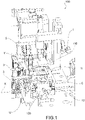
Fig. 1 is an axonometric view of a machine for producing covering capsules for bottle tops according to an embodiment of this invention; -
Fig. 2 is an axonometric view of the machine inFig. 1 , from another viewing angle; -
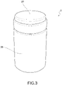
Fig. 3 is an example of a covering capsule for bottle tops obtainable from a machine for producing covering capsules for bottle tops according to this invention. - With reference to the aforesaid figures,
reference numeral 1 has been used to indicate acutting assembly 1 for amachine 100 for producingcovering capsules 2 for bottle tops. -
Fig. 3 is an example of acovering capsule 2 obtainable through themachine 100, provided with acover 20 and ahead disk 21 enclosing the base of thecover 20. Said coveringcapsules 2 are typically used for covering tops and necks of wine bottles or the like and are also known as wine capsules. - According to the invention, the
machine 100 for producing covering capsules for bottle tops comprises a strip unwinding assembly known to the person skilled in the art (not shown), suitable for unwinding a strip made of a plastic material or a metal material, such as PVC, PET or aluminum polylaminate, for producing acovering capsule 2. - The
machine 100 further comprises a dandy roll assembly, also known to the person skilled in the art and not shown in the figures, arranged downstream of the strip unwinding assembly and suitable for transforming the transition movement of the thin strip from a continuous movement to an intermittent movement. - A cutting
assembly feeding station 5 of themachine 100 is arranged downstream of the dandy roll assembly and is suitable for transporting the thin strip to acutting assembly 1 and in particular to a support table 10 of thecutting assembly 1. - The
cutting assembly 1, per se a subject of this invention, comprises a support table 10, suitable for supporting the thin strip made of a plastic material or a metal material for producing acovering capsule 2. - The
cutting assembly 1 further comprises a supporttable movement unit 12 suitable for moving the support table 10 from a cutting position C, in which the support table 10 is arranged to allow the cutting of the thin strip for obtaining athin sheet 11, to an unloading position U, in which the support table is spaced apart from the cutting position C and is positioned close to a next work station, for example awinding station 31, i.e., close to aspindle 3 for winding thethin sheet 11 so as to form thecover 20 of the capsule. - Additionally, the
cutting assembly 1 comprises alaser unit 4, positioned close to the cutting position C and comprising alaser head 41 suitable for emitting a laser beam for laser cutting the thin strip when the support table 10 is in the cutting position C so as to obtain athin sheet 11 intended to be then directly wound in thewinding station 31, for example around aspindle 3. - According to one embodiment, the
laser unit 4 comprises acrosspiece 42 for supporting thelaser head 41. Saidlaser head 41 is thus supported by the supportingcrosspiece 42 above and in a manner spaced apart from the support table 10 when said support table 10 is in the cutting position C. - According to one embodiment, the support
table movement assembly 12 comprises acarriage 120 which is translatable along a longitudinal direction X. In this variant, thecarriage 120 supports the support table 11 and is translatable along said longitudinal direction X from the cutting position C to the unloading position U. - According to an advantageous embodiment, the
cutting assembly 1 comprises suction means, not shown. In this variant, the support table 11 comprisessuction openings 110 operatively connected to the suction means, so that saidsuction openings 110 are suitable for sucking up the thin strip when arranged on the support table 10 to hold it in place during laser cutting to obtain thethin sheet 11. - In this discussion, it is therefore clear that the term "thin strip" refers to the initial thin strip that is unwound in its entirety from a reel for subsequent cutting operations, while the term "thin sheet" 11 refers to a discrete thin sheet, obtained downstream of the laser cutting step and that already has the ideal and final geometry to be wound by a subsequent winding station for the formation of the cover of the covering
capsule 2. - It is clear, therefore, that the
machine 100 according to this invention also comprises awinding station 31, arranged downstream of thecutting assembly 1 and comprising one ormore spindles 3 suitable for receiving thethin sheet 11 cut by thecutting assembly 1 for winding it about the spindle to form thecover 20 of thecapsule 2. - Preferably, extremely advantageously, the
machine 100 is devoid of a blower device for removing the waste generated in the step of cutting the thin strip when the support table 10 is in the cutting position C. This is enabled by the fact that laser cutting allows precise cutting of the desired shape of thethin sheet 11 to be performed immediately. - According to an advantageous embodiment, the cutting
assembly feeding station 5 is configured to carry the thin strip along a main transport direction Y, substantially perpendicular to the longitudinal direction X of translation of thecarriage 120. This results in a machine that is much more compact with respect to the machines of the prior art. - It is moreover an object of this invention to provide a method for cutting a thin strip for producing a
capsule 2 for bottle tops, preferably produced by means of amachine 100 described in the preceding paragraphs. - The method comprises the following operating steps, in the stated order:
- feeding a thin strip from a cutting
assembly feeding station 5 towards a table 10 for supporting the thin strip; - cutting the thin strip by laser cutting performed by a
laser unit 4 for obtaining athin sheet 11 arranged on the support table 10; - moving the support table 10 to a
winding station 31 for winding thethin sheet 11. - Preferably, in the step of cutting the thin strip, the method provides for the laser unit to perform the laser cut at a speed of between 0.5 m/s and 3 m/s, preferably at a power of between 20W and 60W. This results in optimum cutting cycle times for a thin sheet with a thickness of about 0.1 mm, for example between 0.08 and 0.12 mm.
- Preferably, the method comprises the step of preloading a virtual drawing of the laser cut to be made on the thin strip onto a storage medium and sending cutting commands to the
laser unit 4 according to the preloaded virtual drawing. - Innovatively, this invention overcomes the drawbacks of cutting assemblies and machines of the prior art.
- In particular, due to the presence of the laser cutting unit, it is possible to obtain a considerable reduction of the overall dimensions with respect to the machines of the prior art. Moreover, synergistically to the reduction of the overall dimensions, the presence of the laser cutting unit allows for the two cutting steps which are required by the machines of the prior art to be realized in only one cutting step, that is, the first cut for detaching from the strip and the second cut for defining the geometry.
- Moreover, advantageously, the presence of laser cutting allows cutting speeds to be reached up to 50% higher than the cutting speeds reachable by the machines of the prior art, which are instead limited by the movement speed of the blade units.
- Advantageously, the presence of laser cutting allows the production of waste, typical of the prior art, to be eliminated, thereby increasing the productivity of the machine while employing the same amount of strip.
- Moreover, due to the presence of laser cutting, it is possible to quickly change the cutting geometry.
- In addition, the elimination of waste production means that there is no need to use blowing devices, thus further reducing the overall dimensions and allowing the arrangement of the stations that compose the machine to be made more compact, for example by bringing the cutting station closer to the winding station on the spindle, as shown in the accompanying figures.
- Furthermore, the costly blade change operations typical of the prior art are no longer necessary.
- A person skilled in the art may, in order to meet specific needs, make several changes to the embodiments of this invention or substitutions of elements with other functionally equivalent ones.
- These variants are also contained within the scope of protection as defined by the following claims.
Claims (10)
- A cutting assembly (1) for a machine (100) for producing covering capsules (2) for bottle tops, such as wine capsules, said cutting assembly (1) comprising:- a support table (10), suitable for supporting a thin strip made of a plastic material or a metal material for producing a covering capsule (2) for bottle tops;- a support table movement unit (12) suitable to move the support table (10) from a cutting position (C), in which the support table (10) is arranged so as to allow the cutting of the thin strip for obtaining a thin sheet (11), to an unloading position (U), in which the support table is spaced apart from the cutting position (C) and is positioned close to a next work station, for example, close to a spindle (3) for winding the thin sheet (11);- a laser unit (4), positioned close to the cutting position (C) and comprising a laser head (41) suitable for emitting a laser beam for laser cutting the thin strip, when the support table (10) is in the cutting position (C) .
- Cutting assembly (1) according to claim 1, wherein the laser unit (4) comprises a crosspiece (42) for supporting the laser head (41), said laser head (41) being supported by the support crosspiece above and spaced apart from the support table (10), when said support table (10) is in the cutting position.
- Cutting assembly (1) according to claim 1 or 2, wherein the support table movement unit (12) comprises a carriage (120) which is translatable along a longitudinal direction (X),wherein said carriage (120) supports the support table (11),and wherein said carriage (120) is translatable along said longitudinal direction (X) from the cutting position (C) to the unloading position (U).
- Cutting assembly (1) according to any one of the preceding claims, comprising suction means and wherein the support table (11) comprises suction openings (110) operatively connected to the suction means, so that said suction openings (110) are suitable for sucking up the thin strip when arranged on the support table to hold it in place during the laser cutting.
- A machine (100) for producing covering capsules (2) for bottle tops, said machine (100) comprising- a cutting assembly (1) according to any one of the preceding claims- a strip unwinding assembly, suitable for unwinding a strip made of a plastic material or a metal material for producing a covering capsule (2) for bottle tops;- a dandy roll assembly, arranged downstream of the strip unwinding assembly and suitable for transforming the transition movement of the strip from a continuous movement to an intermittent movement;- a cutting assembly feeding station (5), arranged downstream of the dandy roll assembly and suitable for carrying the strip onto the support table (10) of the cutting assembly (1);- a winding station (31), arranged downstream of the cutting assembly (1) and comprising one or more spindles (3) suitable for receiving the thin sheet (11) cut by the cutting assembly (1) for winding it about the spindle to form the cover (20) of the capsule (2).
- Machine for producing covering capsules (2) for bottles according to claim 5, wherein said machine (100) is devoid of a blower device for removing the waste generated during the step of cutting the thin strip, when the support table (10) is in the cutting position (C).
- Machine for producing covering capsules (2) for bottles according to claim 5 or 6, wherein the cutting assembly feeding station (5) is configured to carry the thin strip along a main transverse transport direction (Y), perpendicular to the longitudinal translation direction (X) of the carriage (120).
- A method for cutting a thin strip for producing a capsule (2) for bottle tops comprising the following operating steps, in the stated order, of:- feeding a thin strip from a cutting assembly feeding station (5) towards a table (10) for supporting the thin strip;- cutting the thin strip by laser cutting performed by a laser unit (4) for obtaining a thin sheet (11) arranged on the support table (10);- moving the support table (10) towards a winding station (31) for winding the thin sheet (11).
- Method according to claim 8, wherein the step of cutting the thin strip provides for the laser unit to perform the laser cut at a speed between 1 m/s and 3 m/s.
- Method according to claim 8 or 9, comprising the step of pre-loading, onto a storage medium, a virtual drawing of the laser cut on the thin strip and sending cutting commands to the laser unit according to the pre-loaded virtual drawing.
Applications Claiming Priority (1)
| Application Number | Priority Date | Filing Date | Title |
|---|---|---|---|
| IT102020000029714A IT202000029714A1 (en) | 2020-12-03 | 2020-12-03 | CUTTING UNIT FOR CAPSULE MANUFACTURING MACHINE FOR BOTTLE CAPSULES, MACHINE FOR CAPSULE MANUFACTURING FOR BOTTLE CAPS AND CUTTING METHOD |
Publications (3)
| Publication Number | Publication Date |
|---|---|
| EP4008504A1 true EP4008504A1 (en) | 2022-06-08 |
| EP4008504B1 EP4008504B1 (en) | 2025-10-08 |
| EP4008504C0 EP4008504C0 (en) | 2025-10-08 |
Family
ID=74858526
Family Applications (1)
| Application Number | Title | Priority Date | Filing Date |
|---|---|---|---|
| EP21195574.5A Active EP4008504B1 (en) | 2020-12-03 | 2021-09-08 | Cutting assembly for machine for producing covering capsules for bottle tops, machine for producing covering capsules for bottle tops, and cutting method |
Country Status (3)
| Country | Link |
|---|---|
| EP (1) | EP4008504B1 (en) |
| IT (1) | IT202000029714A1 (en) |
| WO (1) | WO2022118193A1 (en) |
Citations (4)
| Publication number | Priority date | Publication date | Assignee | Title |
|---|---|---|---|---|
| EP0363285A1 (en) * | 1988-09-07 | 1990-04-11 | Pechiney Emballage Alimentaire | Easy to open aluminium protective capsule, and process for its manufacture |
| FR2743059A1 (en) * | 1996-01-02 | 1997-07-04 | Papmetal | Closure plug for wine bottle |
| ITVE970031A1 (en) * | 1997-07-24 | 1999-01-24 | Vencaps Di Rizzetto Lorena | PROCESS FOR FORMING CAPSULONS FOR BOTTLES AND MACHINE TO IMPLEMENT THE PROCEDURE. |
| EP2681125A1 (en) * | 2011-03-01 | 2014-01-08 | E + E Holding BV | Method of manufacturing a screw cap, and a screw cap for closing a preserving jar |
Family Cites Families (1)
| Publication number | Priority date | Publication date | Assignee | Title |
|---|---|---|---|---|
| IT1294582B1 (en) * | 1997-07-24 | 1999-04-12 | Vencaps Di Rizzetto Lorena | PROCEDURE AND EQUIPMENT FOR PRODUCING ALUMINUM LEAF CAPSULES FOR BOTTLES. |
-
2020
- 2020-12-03 IT IT102020000029714A patent/IT202000029714A1/en unknown
-
2021
- 2021-09-08 EP EP21195574.5A patent/EP4008504B1/en active Active
- 2021-11-30 WO PCT/IB2021/061132 patent/WO2022118193A1/en not_active Ceased
Patent Citations (4)
| Publication number | Priority date | Publication date | Assignee | Title |
|---|---|---|---|---|
| EP0363285A1 (en) * | 1988-09-07 | 1990-04-11 | Pechiney Emballage Alimentaire | Easy to open aluminium protective capsule, and process for its manufacture |
| FR2743059A1 (en) * | 1996-01-02 | 1997-07-04 | Papmetal | Closure plug for wine bottle |
| ITVE970031A1 (en) * | 1997-07-24 | 1999-01-24 | Vencaps Di Rizzetto Lorena | PROCESS FOR FORMING CAPSULONS FOR BOTTLES AND MACHINE TO IMPLEMENT THE PROCEDURE. |
| EP2681125A1 (en) * | 2011-03-01 | 2014-01-08 | E + E Holding BV | Method of manufacturing a screw cap, and a screw cap for closing a preserving jar |
Also Published As
| Publication number | Publication date |
|---|---|
| EP4008504B1 (en) | 2025-10-08 |
| IT202000029714A1 (en) | 2022-06-03 |
| EP4008504C0 (en) | 2025-10-08 |
| WO2022118193A1 (en) | 2022-06-09 |
Similar Documents
| Publication | Publication Date | Title |
|---|---|---|
| CA2271141C (en) | Roll-fed labelling apparatus | |
| EP2546052B1 (en) | A machine and a method for producing packaging boxes | |
| US6360801B1 (en) | Method and apparatus for applying self-adhesive protective sheeting to vehicle bodies | |
| EP0224113B1 (en) | Method and apparatus for laser-cutting of composite materials | |
| CN113770521B (en) | Laser cutting marking device, device and method | |
| US4922775A (en) | Device for cutting contoured labels | |
| AU2007267376B2 (en) | Vacuum skin packaging apparatus and process | |
| EP3375600B1 (en) | Contact and non-contact substrate processing | |
| EP2871049B1 (en) | Apparatus for cutting and winding carcass material for tires | |
| EP4008504B1 (en) | Cutting assembly for machine for producing covering capsules for bottle tops, machine for producing covering capsules for bottle tops, and cutting method | |
| US4507995A (en) | Arrangement for removing workpieces from a cutting press | |
| JPH05201737A (en) | Machine for treating flat glass | |
| CN113524781A (en) | A wine box top cover forming machine | |
| CN107234815A (en) | Pressure sensitive adhesive tape automatic assembly line | |
| CN108945558A (en) | Saw blade cutting edge packing machine | |
| KR102897722B1 (en) | System and method for cutting metal films | |
| EP3789306A1 (en) | Method for parting labels from a web of labelling material | |
| JP2000218467A (en) | Automatic control device, automatic control method and recording medium | |
| CN217624478U (en) | Pipe orifice cap shrinking equipment | |
| CN221161373U (en) | Automatic trimming machine for nail polish cover dispensing opening | |
| CN223185304U (en) | A multi-station mold in-mold cutting mechanism | |
| CN218614458U (en) | Cutting machine for foaming sheets | |
| CN212496023U (en) | Die cutting laser machine | |
| CN211331826U (en) | Non-contact novel laser trimming device for metal hollow body | |
| CN211362372U (en) | Automatic wool cutting equipment for glue silk |
Legal Events
| Date | Code | Title | Description |
|---|---|---|---|
| PUAI | Public reference made under article 153(3) epc to a published international application that has entered the european phase |
Free format text: ORIGINAL CODE: 0009012 |
|
| STAA | Information on the status of an ep patent application or granted ep patent |
Free format text: STATUS: THE APPLICATION HAS BEEN PUBLISHED |
|
| AK | Designated contracting states |
Kind code of ref document: A1 Designated state(s): AL AT BE BG CH CY CZ DE DK EE ES FI FR GB GR HR HU IE IS IT LI LT LU LV MC MK MT NL NO PL PT RO RS SE SI SK SM TR |
|
| STAA | Information on the status of an ep patent application or granted ep patent |
Free format text: STATUS: REQUEST FOR EXAMINATION WAS MADE |
|
| 17P | Request for examination filed |
Effective date: 20221110 |
|
| RBV | Designated contracting states (corrected) |
Designated state(s): AL AT BE BG CH CY CZ DE DK EE ES FI FR GB GR HR HU IE IS IT LI LT LU LV MC MK MT NL NO PL PT RO RS SE SI SK SM TR |
|
| GRAP | Despatch of communication of intention to grant a patent |
Free format text: ORIGINAL CODE: EPIDOSNIGR1 |
|
| STAA | Information on the status of an ep patent application or granted ep patent |
Free format text: STATUS: GRANT OF PATENT IS INTENDED |
|
| RIC1 | Information provided on ipc code assigned before grant |
Ipc: B23K 26/38 20140101ALI20250407BHEP Ipc: B23K 26/00 20140101ALI20250407BHEP Ipc: B65H 35/00 20060101ALI20250407BHEP Ipc: B26D 7/01 20060101AFI20250407BHEP |
|
| INTG | Intention to grant announced |
Effective date: 20250506 |
|
| GRAS | Grant fee paid |
Free format text: ORIGINAL CODE: EPIDOSNIGR3 |
|
| GRAA | (expected) grant |
Free format text: ORIGINAL CODE: 0009210 |
|
| STAA | Information on the status of an ep patent application or granted ep patent |
Free format text: STATUS: THE PATENT HAS BEEN GRANTED |
|
| AK | Designated contracting states |
Kind code of ref document: B1 Designated state(s): AL AT BE BG CH CY CZ DE DK EE ES FI FR GB GR HR HU IE IS IT LI LT LU LV MC MK MT NL NO PL PT RO RS SE SI SK SM TR |
|
| REG | Reference to a national code |
Ref country code: GB Ref legal event code: FG4D Ref country code: CH Ref legal event code: F10 Free format text: ST27 STATUS EVENT CODE: U-0-0-F10-F00 (AS PROVIDED BY THE NATIONAL OFFICE) Effective date: 20251008 |
|
| REG | Reference to a national code |
Ref country code: DE Ref legal event code: R096 Ref document number: 602021039961 Country of ref document: DE |
|
| REG | Reference to a national code |
Ref country code: IE Ref legal event code: FG4D |
|
| U01 | Request for unitary effect filed |
Effective date: 20251009 |
|
| U07 | Unitary effect registered |
Designated state(s): AT BE BG DE DK EE FI FR IT LT LU LV MT NL PT RO SE SI Effective date: 20251017 |
|
| PG25 | Lapsed in a contracting state [announced via postgrant information from national office to epo] |
Ref country code: ES Free format text: LAPSE BECAUSE OF FAILURE TO SUBMIT A TRANSLATION OF THE DESCRIPTION OR TO PAY THE FEE WITHIN THE PRESCRIBED TIME-LIMIT Effective date: 20251008 |
|
| PG25 | Lapsed in a contracting state [announced via postgrant information from national office to epo] |
Ref country code: NO Free format text: LAPSE BECAUSE OF FAILURE TO SUBMIT A TRANSLATION OF THE DESCRIPTION OR TO PAY THE FEE WITHIN THE PRESCRIBED TIME-LIMIT Effective date: 20260108 |
|
| PG25 | Lapsed in a contracting state [announced via postgrant information from national office to epo] |
Ref country code: HR Free format text: LAPSE BECAUSE OF FAILURE TO SUBMIT A TRANSLATION OF THE DESCRIPTION OR TO PAY THE FEE WITHIN THE PRESCRIBED TIME-LIMIT Effective date: 20251008 |
|
| PG25 | Lapsed in a contracting state [announced via postgrant information from national office to epo] |
Ref country code: RS Free format text: LAPSE BECAUSE OF FAILURE TO SUBMIT A TRANSLATION OF THE DESCRIPTION OR TO PAY THE FEE WITHIN THE PRESCRIBED TIME-LIMIT Effective date: 20260108 |
|
| PG25 | Lapsed in a contracting state [announced via postgrant information from national office to epo] |
Ref country code: IS Free format text: LAPSE BECAUSE OF FAILURE TO SUBMIT A TRANSLATION OF THE DESCRIPTION OR TO PAY THE FEE WITHIN THE PRESCRIBED TIME-LIMIT Effective date: 20260208 |
|
| PG25 | Lapsed in a contracting state [announced via postgrant information from national office to epo] |
Ref country code: PL Free format text: LAPSE BECAUSE OF FAILURE TO SUBMIT A TRANSLATION OF THE DESCRIPTION OR TO PAY THE FEE WITHIN THE PRESCRIBED TIME-LIMIT Effective date: 20251008 |