EP4008468A1 - Thread milling tool and thread milling insert - Google Patents
Thread milling tool and thread milling insert Download PDFInfo
- Publication number
- EP4008468A1 EP4008468A1 EP20211239.7A EP20211239A EP4008468A1 EP 4008468 A1 EP4008468 A1 EP 4008468A1 EP 20211239 A EP20211239 A EP 20211239A EP 4008468 A1 EP4008468 A1 EP 4008468A1
- Authority
- EP
- European Patent Office
- Prior art keywords
- insert
- thread milling
- seat
- seats
- tool
- Prior art date
- Legal status (The legal status is an assumption and is not a legal conclusion. Google has not performed a legal analysis and makes no representation as to the accuracy of the status listed.)
- Pending
Links
- 238000003801 milling Methods 0.000 title claims abstract description 241
- 238000005520 cutting process Methods 0.000 claims abstract description 94
- 230000002093 peripheral effect Effects 0.000 claims description 36
- 230000002349 favourable effect Effects 0.000 description 3
- 238000000227 grinding Methods 0.000 description 3
- 238000004519 manufacturing process Methods 0.000 description 3
- 238000005553 drilling Methods 0.000 description 2
- 238000003754 machining Methods 0.000 description 2
- 230000001154 acute effect Effects 0.000 description 1
- 230000001419 dependent effect Effects 0.000 description 1
- 238000009826 distribution Methods 0.000 description 1
- 238000000034 method Methods 0.000 description 1
- 238000012986 modification Methods 0.000 description 1
- 230000004048 modification Effects 0.000 description 1
- 238000005728 strengthening Methods 0.000 description 1
Images





Classifications
-
- B—PERFORMING OPERATIONS; TRANSPORTING
- B23—MACHINE TOOLS; METAL-WORKING NOT OTHERWISE PROVIDED FOR
- B23G—THREAD CUTTING; WORKING OF SCREWS, BOLT HEADS, OR NUTS, IN CONJUNCTION THEREWITH
- B23G5/00—Thread-cutting tools; Die-heads
- B23G5/18—Milling cutters
-
- B—PERFORMING OPERATIONS; TRANSPORTING
- B23—MACHINE TOOLS; METAL-WORKING NOT OTHERWISE PROVIDED FOR
- B23C—MILLING
- B23C5/00—Milling-cutters
- B23C5/02—Milling-cutters characterised by the shape of the cutter
- B23C5/10—Shank-type cutters, i.e. with an integral shaft
- B23C5/109—Shank-type cutters, i.e. with an integral shaft with removable cutting inserts
-
- B—PERFORMING OPERATIONS; TRANSPORTING
- B23—MACHINE TOOLS; METAL-WORKING NOT OTHERWISE PROVIDED FOR
- B23C—MILLING
- B23C2200/00—Details of milling cutting inserts
- B23C2200/04—Overall shape
- B23C2200/0416—Irregular
-
- B—PERFORMING OPERATIONS; TRANSPORTING
- B23—MACHINE TOOLS; METAL-WORKING NOT OTHERWISE PROVIDED FOR
- B23G—THREAD CUTTING; WORKING OF SCREWS, BOLT HEADS, OR NUTS, IN CONJUNCTION THEREWITH
- B23G2200/00—Details of threading tools
- B23G2200/10—Threading tools comprising cutting inserts
Definitions
- the present invention relates to a thread milling tool according to the preamble of claim 1.
- the invention also relates to a thread milling insert intended for use in such a thread milling tool.
- a thread milling tool is a rotating cutting tool used for cutting threads in a workpiece.
- a thread milling tool may be provided with one or more cutting inserts detachably mounted in a respective insert seat in a tool body of the thread milling tool. These cutting inserts are in the following referred to as thread milling inserts.
- a thread milling insert is normally provided with a plurality of teeth arranged one after the other in a row along a peripheral side of the thread milling insert, wherein the cutting edges of the thread milling insert are formed on these teeth.
- Each thread milling insert is with advantage double-sided in order to increase the useful life thereof, wherein each tooth has a first cutting edge on a first side of the tooth and a corresponding second cutting edge on an opposite second side of the tooth.
- a thread milling tool with double-sided thread milling inserts is previously known from EP 1 198 321 B1 .
- the thread milling insert may be repositioned in its insert seat and mounted in a new inverted working position with the cutting edges on the other side of the teeth in an active cutting position.
- each individual thread milling insert has a rather long extension as seen in the longitudinal direction of the tool body.
- a thread milling tool with detachable thread milling inserts may as an alternative be provided with insert seats that are axially offset from each other in the longitudinal direction of the tool body and consequently located at mutually different axial positions in the tool body.
- the cutting profile of the thread milling tool is divided into separate parts, as seen in the longitudinal direction of the tool body, with a first part of the cutting profile formed by cutting edges on the teeth of a number of first thread milling inserts located in a corresponding number of first insert seats located close to a front end of the tool body and with a second part of the cutting profile formed by cutting edges on the teeth of a number of second thread milling inserts located in a corresponding number of second insert seats located further away from the front end of the tool body.
- a thread milling tool of the last-mentioned type is for instance disclosed in WO 2010/101512 A2 .
- the object of the present invention is to provide a thread milling tool of the above-mentioned type that has a new and favourable design.
- the thread milling tool according to the invention comprises:
- each thread milling insert has the form of a double-sided insert with the same cutting edge profile formed on both sides of the teeth on the insert body of the thread milling insert, wherein the distance between the axial abutment surface on the thread milling insert and the proximate end of the cutting edge profile formed by the first group of cutting edges is equal, within manufacturing tolerances, to the distance between the axial abutment surface and the proximate end of the other cutting edge profile formed by the second group of cutting edges.
- the axial support surfaces in the first and second insert seats of said at least one pair of insert seats are arranged in one of the following to alternative manners:
- thread milling inserts are adapted to the first and second insert seats of said at least one pair of insert seats in such a manner that each one of the thread milling inserts is:
- the thread milling inserts have the form of double-sided inserts and each one of them is mountable to the tool body in two different working positions.
- the double-sided thread milling inserts included in the thread milling tool of the present invention are each provided with one single axial abutment surface, which is used for defining the axial position of the thread milling insert in the tool body in both of the two possible working positions of the thread milling insert.
- the thread milling insert in order to bring the cutting edges on the other side of the teeth into an active cutting position, the thread milling insert has to be moved from its present insert seat to another insert seat that has another axial position in the tool body than the present insert seat.
- An incorrect mounting of an individual thread milling insert is hereby prevented in an efficient and simple manner, which in its turn implies that the operation for repositioning of the thread milling inserts may be effected quickly and easily.
- one and the same surface on a thread milling insert is used as axial abutment surface in both working positions of the thread milling insert, i.e. when the thread milling insert is mounted in an insert seat with the first group of cutting edges in operative position and also when the thread milling insert is mounted in another insert seat with the second group of cutting edges in operative position.
- the surface in question i.e. the surface used as axial abutment surface, can be used as an axial reference plane during the grinding of the first group of cutting edges on the first side of the teeth on the thread milling insert and also during the grinding of the second group of cutting edges on the opposite second side of the teeth, which is favourable with respect to the tolerances of the thread milling insert.
- the first group of cutting edges on the first side of the teeth on the thread milling insert and the second group of cutting edges on the opposite second side of the teeth may also be grinded at the same time, in one grinding operation, with the same axial abutment surface as axial reference plane.
- the surface on the insert body opposite to the axial abutment surface does not need to be grinded because it does not constitute an axial abutment surface. Due to that, a tolerance of a distance between the axial abutment surface and the surface opposite to the axial abutment surface does not give a contribution to a total tolerance of the tool when the inserts are mounted in the tool body.
- the tolerances of a thread milling tool provided with these shorter thread milling inserts mounted at two different axial positions in the tool body are not deteriorated as compared to a corresponding thread milling tool provided with longer thread milling inserts where the teeth on each individual thread milling insert cover the entire cutting profile of the thread milling tool, as seen in the longitudinal direction of the tool body.
- each thread milling insert preferably also comprises a radial abutment surface, which is formed on a peripheral side of the insert body opposite to the peripheral side provided with the teeth and which is configured to abut against a corresponding radial support surface in any of the first and second insert seats when the thread milling insert is mounted in the insert seat in question.
- the insert body of each one of the thread milling inserts has:
- the shape of the insert body of each one of the thread milling inserts is preferably so adapted to the shape of the first and second insert seats that the insert body fits into the first insert seat, i.e. may be mounted in the first insert seat, only in a position with the axial abutment surface on the insert body abutting against the axial support surface in the first insert seat and fits into the second insert seat, i.e. may be mounted in the second insert seat, only in a position with the axial abutment surface on the insert body abutting against the axial support surface in the second insert seat.
- This may for instance be achieved by giving the insert body of each one of the thread milling inserts such a design that an end section at the first end of the insert body has a shape that differs from the shape of a corresponding end section at the opposite second end of the insert body.
- a mounting of a thread milling insert in an incorrect position in any of the insert seats may be prevented in a simple and efficient manner.
- This may also be achieved by giving the insert body of each one of the thread milling inserts such a design that the insert body comprises a fastening means for fastening of the thread milling insert in any of the first and second insert seats, which fastening means is arranged at different positions in relation to the first end and the second end of the insert body.
- each one of the thread milling inserts may be provided with:
- the axial abutment surface on the insert body of each one of the thread milling inserts is formed by an end surface on the insert body at the first end thereof.
- the first insert seats may be open towards a front end surface of the tool body, i.e. with the first end of each first insert seat formed as an opening in said front end surface, or with a small material portion between the front end surface of the tool body and the first end of each first insert seat.
- the tool is adapted for machining of threads closer to a bottom of the hole in the work piece and is better adapted for machining where fixturing of the work piece is demanding.
- the insert body of each one of the thread milling inserts may be provided with:
- first and second insert seats of said at least one pair of insert seats may have such axial positions in relation to each other in the tool body that the axial distance between the tooth closest to the second end of the first insert seat on a thread milling insert mounted in the first insert seat and the tooth closest to the first end of the second insert seat on a thread milling insert mounted in the second insert seat is substantially equal to the axial distance between two adjacent teeth on any of these thread milling inserts.
- first and second insert seats of said at least one pair of insert seats may as an alternative have such axial positions in relation to each other in the tool body that the tooth closest to the second end of the first insert seat on a thread milling insert mounted in the first insert seat and the tooth closest to the first end of the second insert seat on a thread milling insert mounted in the second insert seat are located at the same axial position in the tool body and thereby overlap each other in the longitudinal direction of the tool body.
- two or more such pairs of insert seats are provided in the tool body, wherein the first insert seats of the different pairs of insert seats are located at the same axial position in the tool body and are evenly distributed about the longitudinal axis of the tool body, and wherein the second insert seats of the different pairs of insert seats are located at the same axial position in the tool body and are evenly distributed about the longitudinal axis of the tool body.
- the invention also relates to a thread milling insert intended for use in a thread milling tool of the above-mentioned type.
- the thread milling insert according to the invention comprises:
- the insert body has:
- the thread milling insert has the form of a double-sided insert with the same cutting edge profile formed on both sides of the teeth on the insert body, wherein the distance between the axial abutment surface and the proximate end of the cutting edge profile on a first side of the teeth is equal, within manufacturing tolerances, to the distance between the abutment surface and the proximate end of the other cutting edge profile on the opposite second side of the teeth.
- the above-mentioned mirror asymmetry and rotational asymmetry of the insert body implies that the insert seats of a thread milling tool easily may be adapted to the shape of the insert body in such a manner that the thread milling insert is mountable in one single predetermined working position in each insert seat.
- a thread milling insert having an insert body of this design is suitable for use in a thread milling tool of the type described above.
- the insert body is considered to have mirror symmetry with respect to its median plane even if any of the surfaces of the insert body is provided with one or more minor markings, for instance in the form of recesses, that lack a mirror-symmetry image with respect to the median plane of the insert body, on condition that these one or more markings have no relevance for the functioning of the thread milling insert.
- the thread milling tool 1 comprises an elongated tool body 2 and is configured to be rotated about an axis of rotation 3.
- the tool body 2 has a front end 2a and an opposite rear end 2b.
- a longitudinal axis 4 of the tool body 2 extends between the rear end 2b and the front end 2a of the tool body, wherein this longitudinal axis 4 coincides with the axis of rotation 3 of the thread milling tool 1.
- a collar 5 is provided at the middle of the tool body 2.
- a rear part of the tool body located between the collar 5 and the rear end 2b forms a connection member 6, through which the tool body 2 is mountable, directly or via an intermediate tool holder, to a rotating spindle or the similar of a machine, for instance a milling machine or a drilling machine.
- a front part of the tool body 2 located between the collar 5 and the front end 2a is provided with insert seats 10, 20 configured to receive thread milling insert 30.
- the insert seats 10, 20 are arranged in pairs, wherein each pair consists of a first insert seat 10 located close to the front end 2a of the tool body 2 and a second insert seat 20 located further away from the front end 2a of the tool body 2.
- first and second insert seats 10, 20 are axially offset from each other in the longitudinal direction of the tool body 2 with the first insert seat 10 located closer to the front end 2a of the tool body 2 than the second insert seat 20. Furthermore, the first and second insert seats 10, 20 are angularly offset from each other with respect to the longitudinal axis 4 of the tool body 2.
- the first insert seat 10 extends in the longitudinal direction of the tool body 2 and has a first end 10a and an opposite second end 10b, wherein the first end 10a of the first insert seat is located closer to the front end 2a of the tool body 2 than the second end 10b of the first insert seat.
- the second insert seat 20 extends in the longitudinal direction of the tool body 2 in parallel with the first insert seat 10 and has a first end 20a and an opposite second end 20b, wherein the first end 20a of the second insert seat is located closer to the front end 2a of the tool body 2 than the second end 20b of the second insert seat.
- the tool body 2 is provided with two pairs of insert seats 10, 20 of the above-mentioned type.
- the tool body 2 is provided with three pairs of insert seats 10, 20 of the above-mentioned type.
- the tool body 2 may as an alternative, inter alia depending on the diameter of the tool body, be provided with any other suitable number of insert seats.
- a smaller diameter tool body may for instance be provided with only one pair of insert seats 10, 20, whereas a larger diameter tool body may be provided with more than three pairs of insert seats 10, 20.
- the first insert seats 10 of the different pairs are mutually located at the same axial position in the tool body 2 and are evenly distributed about the longitudinal axis 4 of the tool body.
- the second insert seats 20 of the different pairs are mutually located at the same axial position in the tool body 2 and are evenly distributed about the longitudinal axis 4 of the tool body.
- the first and second insert seats 10, 20 are alternately arranged as seen in the circumferential direction of the tool body 2.
- each first insert seat 10 is arranged between two second insert seats 20 and each second insert seat 20 is arranged between two first insert seats.
- Each insert seat 10, 20 is configured to receive one thread milling insert 30.
- the thread milling inserts 30 received in the first and second insert seats 10, 20 are geometrically identical to each other, or at least substantially geometrically identical to each other.
- the thread milling inserts 30 included in one and the same thread milling tool 1 all have the same basic shape and are of the same size.
- the thread milling inserts 30 have the form of double-sided inserts and are detachably mountable in the insert seats 10, 20.
- Each thread milling insert 30 comprises an elongated insert body 31 having a first end 31a and an opposite second end 31b.
- the insert body 31 comprises first and second major faces 32, 33, which are arranged on opposite sides of the insert body 31 and which serve as top and bottom faces of the thread milling insert 30.
- the first and second major faces 32, 33 of the insert body 31 extend between the first and second ends 31a, 31b of the insert body 31.
- a median plane MP which constitutes an imaginary plane, extends halfway between the first and second major faces 32, 33 of the insert body 31, as illustrated in Figs 10 and 20 .
- Each thread milling insert 30 further comprises a plurality of teeth 34 arranged one after the other in a row along a peripheral side 35 of the insert body 31 that is located between the first and second major faces 32, 33 and that extends between the first and second ends 31a, 31b of the insert body 31.
- Each tooth 34 has a first side surface 37, an opposite second side surface 38 and a peripheral surface 39 extending between the first and second side surfaces 37, 38.
- a first cutting edge 40a is formed at an intersection between the peripheral surface 39 and the first side surface 37 and a second cutting edge 40b is formed at an intersection between the peripheral surface 39 and the second side surface 38.
- the first cutting edge 40a is arranged on a first side of the tooth 34 facing the first major face 32 of the insert body 31 and the second cutting edge 40b is arranged on an opposite second side of the tooth 34 facing the second major face 33 of the tool body 31.
- the first and second cutting edges 40a, 40b may extend along the entire or substantially the entire line of intersection between the peripheral surface 39 and the first side surface 37 and the second side surface 38, respectively, or at least along a part thereof at the tip of the tooth 34. In the latter case, each one of the first and second cutting edges 40a, 40b ends at a distance from the base of the tooth 34 on either side of the tip of the tooth.
- the first side surface 37 is configured to serve as a rake face for the first cutting edge 40a
- the second side surface 38 is configured to serve as a rake face for the second cutting edge 40b.
- the peripheral surface 39 serves as a relief surface for the first and second cutting edges 40a, 40b and extends perpendicularly to the median plane MP, as illustrated in Figs 10 and 20 .
- first and second side surfaces 37, 38 of each tooth 34 are inclined outwards, at an acute angle ⁇ to each other, as seen in a direction from the base of the tooth towards the tip thereof, as illustrated in Figs 10 and 20 .
- the first cutting edges 40a of the teeth 34 on each individual thread milling insert 30 form a first group of cutting edges of the thread milling insert and the second cutting edges 40b of the teeth 34 form a second group of cutting edges of the thread milling insert.
- the first group of cutting edges 40a and the second group of cutting edges 40b are mirror symmetrical to each other with respect to the median plane MP of the insert body 31.
- Each thread milling insert 31 is provided with three teeth 34 in the embodiment illustrated in Figs 1-10 and with seven teeth 34 in the embodiment illustrated in Figs 11-20 .
- the thread milling inserts 31 may be provided with any other suitable number of teeth 34.
- each thread milling insert 30 is provided with a fastening means in the form of two through holes 42, which extend in parallel with each other through the insert body 31 between the first and second major faces 32, 33.
- Each through hole 42 has a centre axis CA that extends perpendicularly to the first and second major faces 32, 33.
- Each through hole 42 is configured to receive a fastening element 8, for instance in the form of a screw, by means of which the thread milling insert 30 may be releasably fixed in any of the insert seats 10, 20 in the tool body 2.
- the thread milling inserts 30 may as a further alternative lack a through hole 42, wherein each thread milling insert 30 is configured to be releasably fixed to any of the insert seats in the tool body by means of suitable clamping means.
- each thread milling insert 30 is provided with an axial abutment surface 41, which is located at the first end 31a of the insert body 31 and which is configured to abut against a corresponding axial support surface 11 in any of the first insert seats 10 when the thread milling insert 30 is mounted in the first insert seat in question and to abut against a corresponding axial support surface 21 in any of the second insert seat 20 when the thread milling insert 30 is mounted in the second insert seat in question.
- each insert seat 10, 20 is provided with an axial support surface 11, 21 configured for engagement with the axial abutment surface 41 on the insert body 31 of a thread milling insert 30 when the thread milling insert 30 is mounted in the insert seat 10, 20.
- each first insert seat 10 is located at the second end 10b of the first insert seat and faces the front end 2a of the tool body 2
- the axial support surface 21 in each second insert seat 20 is located at the first end 20a of the second insert seat and faces the rear end 2b of the tool body 2.
- the first insert seats 10 may be open towards a front end surface 7 of the tool body 2, i.e. with the first end 10a of each first insert seat 10 formed as an opening in said front end surface 7.
- each first insert seat 10 is located at the first end 10a of the first insert seat and faces the rear end 2b of the tool body 2
- the axial support surface 21 in each second insert seat 20 is located at the second end 20b of the second insert seat and faces the front end 2a of the tool body 2.
- the axial abutment surface 41 on the insert body 31 of each thread milling insert 30 is formed by an end surface on the insert body 31 at the first end 31a thereof.
- the axial abutment surface 41 is preferably a plane surface that extends perpendicularly to the median plane MP of the insert body 31, wherein the axial support surface 11, 21 in each insert seat 10, 20 is a plane surface that extends perpendicularly to the longitudinal axis 4 of the tool body 2.
- the axial abutment surface 41 and the axial support surfaces 11, 21 may also have any other suitable and mutually matching shapes.
- each thread milling insert 30 is also provided with a radial abutment surface 43 formed on a peripheral side 45 of the insert body opposite to the peripheral side 35 provided with the teeth 34, wherein this radial abutment surface 43 is configured to abut against a corresponding radial support surface 13 in any of the first insert seats 10 when the thread milling insert 30 is mounted in the first insert seat in question and to abut against a corresponding radial support surface 23 in any of the second insert seat 20 when the thread milling insert 30 is mounted in the second insert seat in question.
- the radial abutment surface 43 is preferably perpendicular to the axial abutment surface 41.
- each insert seat 10, 20 is provided with a radial support surface 13, 23 configured for engagement with the radial abutment surface 43 on the insert body 31 of a thread milling insert 30 when the thread milling insert 30 is mounted in the insert seat 10, 20.
- the radial support surface 13, 23 is preferably perpendicular to the axial support surface 11, 21.
- each thread milling insert 30 is configured to be releasably fixed to any of the insert seats 10, 20 in the tool body 2 by means of two fastening elements 8 in the form of screws, which extend through a respective one of the through holes 42 in the insert body 31 of the thread milling insert and is engaged in a threaded hole 12, 22 (see Figs 2-4 and 12-14 ) in a tangential support surface 14, 24 in the insert seat.
- Each fastening element 8 comprises an elongated shaft 8a, which is provided with an external thread configured for engagement with a corresponding internal thread in any of said threaded holes 12, 22, and a head 8b, which is fixed to the shaft 8a.
- the shaft 8a has an external diameter that is smaller than the internal diameter of the through holes 42 in the insert body 31 such that the shaft 8a is receivable with play in any of the through holes 42, as illustrated in Figs 7, 8 , 17 and 18 .
- Each through hole 42 is provided with a conically shaped internal surface 42a at each of its ends configured for engagement with a corresponding conically shaped external surface 8c on the head 8b of each fastening element.
- each thread milling insert 30 is:
- the shape of the insert body 31 of each thread milling insert 30 is so adapted to the shape of the first and second insert seats 10, 20 that the insert body 31 fits into any of the first insert seats 10 only in a position with the axial abutment surface 41 on the insert body 31 abutting against the axial support surface 11 in the first insert seat 10 and into any of the second insert seats 20 only in a position with the axial abutment surface 41 on the insert body 31 abutting against the axial support surface 21 in the second insert seat 20.
- the insert body 31 of each thread milling insert 30 has a first end section 46a at its first end 31a with a shape that differs from the shape of a corresponding second end section 46b at its opposite second end 31b.
- each one of the first and second insert seat 10, 20 has a first end section 16a, 26a (see Figs 3, 4 , 13 and 14 ) at one 10b, 20a of its ends with a shape adapted to the shape of the first end section 46a of the insert body 31 of each thread milling insert 30 and a differently shaped second end section 16b, 26b (see Figs 3, 4 , 13 and 14 ) at its other end 10a, 20b with a shape adapted to the shape of the second end section 46b of the insert body 31 of each thread milling insert 30.
- the above-mentioned first end section 46a of the insert body 31 comprises an inclined peripheral side surface 47, which forms a connection between the axial and radial abutment surfaces 41, 43 on the insert body 31 and which is configured to face a corresponding inclined surface 17, 27 at the first end section 16a, 26a of any of the first and second insert seats 10, 20 when the thread milling insert 30 is mounted in the insert seat in question.
- the opposite second end section 46b of the insert body 31 lacks such an inclined peripheral side surface to thereby prevent the second end section 46b of the insert body 31 to fit into the first end section 16a, 26a of any of the first and second insert seats 10, 20.
- the above-mentioned inclined surfaces 17, 27 form a respective bevelled corner at the first end section 16a, 26a of the first and second insert seats 10, 20 that, together with the non-inclined second end section 46b of the insert body 31, will prevent the thread milling insert 31 from being mounted in any of the insert seats 10, 20 with the second end 31b of the insert body facing the axial support surface 11, 21 in the insert seat.
- the first and second ends 31a, 31b of the insert body 31 of the thread milling insert 30 have the same shape.
- the positions of the through holes 42 in the insert body 31 have been moved towards the second end 31b of the insert body, as compared to the symmetric arrangement of the through holes 42 in the insert body 31 in the embodiments illustrated in Figs 1-20 .
- the asymmetric arrangement of the through holes 42 in the insert body 31 and a corresponding arrangement of the threaded holes 12, 22 in the insert seats 10 20 ensure that the thread milling insert 30 can only be mounted in one single working position in each insert seat 10, 20.
- the insert body 31 of each thread milling insert 30 has:
- the first and second insert seats 10, 20 have such axial positions in relation to each other in the tool body 2 that the axial distance between the tooth 34 closest to the second end 10b of a first insert seat 10 on a thread milling insert 30 mounted in any of the first insert seats 10 and the tooth 34 closest to the first end 20a of an adjacent second insert seat 20 on a thread milling insert 30 mounted in this second insert seat 20 is substantially equal to the axial distance between two adjacent teeth 34 on any of these thread milling inserts.
- the first and second insert seats 10, 20 have such axial positions in relation to each other in the tool body 2 that the tooth 34 closest to the second end 10b of a first insert seat 10 on a thread milling insert 30 mounted in any of the first insert seats 10 and the tooth 34 closest to the first end 20a of an adjacent second insert seat 20 on a thread milling insert 30 mounted in this second insert seat 20 are located at the same axial position in the tool body 2 and thereby overlap each other, as seen in the longitudinal direction of the tool body 2.
Landscapes
- Engineering & Computer Science (AREA)
- Mechanical Engineering (AREA)
- Milling Processes (AREA)
Abstract
- mountable in the first insert seat (10) in one single working position with a first group of cutting edges (40a) on a first side of the thread milling insert in an active cutting position, and
- mountable in the second insert seat (20) in one single working position with a second group of cutting edges (40b) on an opposite second side of the thread milling insert in an active cutting position.
Description
- The present invention relates to a thread milling tool according to the preamble of
claim 1. The invention also relates to a thread milling insert intended for use in such a thread milling tool. - A thread milling tool is a rotating cutting tool used for cutting threads in a workpiece. A thread milling tool may be provided with one or more cutting inserts detachably mounted in a respective insert seat in a tool body of the thread milling tool. These cutting inserts are in the following referred to as thread milling inserts. A thread milling insert is normally provided with a plurality of teeth arranged one after the other in a row along a peripheral side of the thread milling insert, wherein the cutting edges of the thread milling insert are formed on these teeth. Each thread milling insert is with advantage double-sided in order to increase the useful life thereof, wherein each tooth has a first cutting edge on a first side of the tooth and a corresponding second cutting edge on an opposite second side of the tooth.
- A thread milling tool with double-sided thread milling inserts is previously known from
EP 1 198 321 B1EP 1 198 321 B1 - In the thread milling tool disclosed in
EP 1 198 321 B1WO 2010/101512 A2 . - The object of the present invention is to provide a thread milling tool of the above-mentioned type that has a new and favourable design.
- According to the invention, said object is achieved by means of a thread milling tool having the features defined in
claim 1. - The thread milling tool according to the invention comprises:
- an elongated tool body having a front end and an opposite rear end, the rear end being configured for attachment to a machine, for instance in the form of a milling machine or a drilling machine, wherein a longitudinal axis of the tool body extends between the rear end and the front end of the tool body;
- at least one pair of insert seats provided in the tool body and consisting of a first insert seat and a second insert seat, the first and second inserts seats being angularly offset from each other with respect to the longitudinal axis of the tool body and axially offset from each other in the longitudinal direction of the tool body with the first insert seat located closer to the front end of the tool body than the second insert seat, wherein each one of the first and second insert seats has a first end and an opposite second end, the first end of each one of the first and second insert seats being arranged closer to the front end of the tool body than the opposite second end of the same insert seat; and
- several substantially geometrically identical thread milling inserts, each of which being detachably mountable in a respective insert seat and comprising:
- an elongated insert body having a first end and an opposite second end, wherein the insert body comprises first and second major faces arranged on opposite sides of the insert body and serving as top and bottom faces of the thread milling insert, and wherein the insert body is provided with an axial abutment surface, which is located at the first end of the insert body and which is configured to abut against a corresponding axial support surface in the first insert seat when the thread milling insert is mounted in the first insert seat and to abut against a corresponding axial support surface in the second insert seat when the thread milling insert is mounted in the second insert seat, and
- a plurality of teeth, preferably three or more in number, arranged one after the other in a row along a peripheral side of the insert body that is located between the first and second major faces and that extends between the first and second ends of the insert body, wherein each tooth has a first cutting edge on a first side of the tooth facing the first major face and a second cutting edge on an opposite second side of the tooth facing the second major face, the first cutting edges of the teeth forming a first group of cutting edges and the second cutting edges of the teeth forming a second group of cutting edges, wherein the first group of cutting edges and the second group of cutting edges are mirror symmetrical to each other with respect to a median plane of the insert body that extends halfway between the first and second major faces of the insert body.
- The above-mentioned mirror symmetry of the first and second groups of cutting edges implies that each thread milling insert has the form of a double-sided insert with the same cutting edge profile formed on both sides of the teeth on the insert body of the thread milling insert, wherein the distance between the axial abutment surface on the thread milling insert and the proximate end of the cutting edge profile formed by the first group of cutting edges is equal, within manufacturing tolerances, to the distance between the axial abutment surface and the proximate end of the other cutting edge profile formed by the second group of cutting edges.
- The axial support surfaces in the first and second insert seats of said at least one pair of insert seats are arranged in one of the following to alternative manners:
- A) with the axial support surface in the first insert seat located at the second end of the first insert seat and facing the front end of the tool body, and the axial support surface in the second insert seat located at the first end of the second insert seat and facing the rear end of the tool body; or
- B) with the axial support surface in the first insert seat located at the first end of the first insert seat and facing the rear end of the tool body, and the axial support surface in the second insert seat located at the second end of the second insert seat and facing the front end of the tool body.
- Furthermore, the thread milling inserts are adapted to the first and second insert seats of said at least one pair of insert seats in such a manner that each one of the thread milling inserts is:
- mountable in the first insert seat in one single working position with the axial abutment surface on the insert body of the thread milling insert abutting against the axial support surface in the first insert seat and with one of said first and second groups of cutting edges in an active cutting position, i.e. in operative position, and
- mountable in the second insert seat in one single working position with the axial abutment surface on the insert body of the thread milling insert abutting against the axial support surface in the second insert seat and with the other one of said first and second groups of cutting edges in an active cutting position.
- Thus, the thread milling inserts have the form of double-sided inserts and each one of them is mountable to the tool body in two different working positions. However, in contrast to double-sided thread milling inserts of conventional type, the double-sided thread milling inserts included in the thread milling tool of the present invention are each provided with one single axial abutment surface, which is used for defining the axial position of the thread milling insert in the tool body in both of the two possible working positions of the thread milling insert. When the cutting edges on one side of the teeth of a thread milling insert included in the thread milling tool of the present invention has been worn out, the thread milling insert cannot be repositioned and mounted in a new inverted working position in the same insert seat. On the contrary, in order to bring the cutting edges on the other side of the teeth into an active cutting position, the thread milling insert has to be moved from its present insert seat to another insert seat that has another axial position in the tool body than the present insert seat. An incorrect mounting of an individual thread milling insert is hereby prevented in an efficient and simple manner, which in its turn implies that the operation for repositioning of the thread milling inserts may be effected quickly and easily.
- According to the invention, one and the same surface on a thread milling insert is used as axial abutment surface in both working positions of the thread milling insert, i.e. when the thread milling insert is mounted in an insert seat with the first group of cutting edges in operative position and also when the thread milling insert is mounted in another insert seat with the second group of cutting edges in operative position. This implies that the surface in question, i.e. the surface used as axial abutment surface, can be used as an axial reference plane during the grinding of the first group of cutting edges on the first side of the teeth on the thread milling insert and also during the grinding of the second group of cutting edges on the opposite second side of the teeth, which is favourable with respect to the tolerances of the thread milling insert. The first group of cutting edges on the first side of the teeth on the thread milling insert and the second group of cutting edges on the opposite second side of the teeth may also be grinded at the same time, in one grinding operation, with the same axial abutment surface as axial reference plane. The surface on the insert body opposite to the axial abutment surface does not need to be grinded because it does not constitute an axial abutment surface. Due to that, a tolerance of a distance between the axial abutment surface and the surface opposite to the axial abutment surface does not give a contribution to a total tolerance of the tool when the inserts are mounted in the tool body. With this design of the thread milling inserts, the tolerances of a thread milling tool provided with these shorter thread milling inserts mounted at two different axial positions in the tool body are not deteriorated as compared to a corresponding thread milling tool provided with longer thread milling inserts where the teeth on each individual thread milling insert cover the entire cutting profile of the thread milling tool, as seen in the longitudinal direction of the tool body.
- The insert body of each thread milling insert preferably also comprises a radial abutment surface, which is formed on a peripheral side of the insert body opposite to the peripheral side provided with the teeth and which is configured to abut against a corresponding radial support surface in any of the first and second insert seats when the thread milling insert is mounted in the insert seat in question.
- According to an embodiment of the invention, the insert body of each one of the thread milling inserts has:
- mirror symmetry with respect to the median plane of the insert body,
- mirror asymmetry with respect to any other plane across the insert body, and
- rotational asymmetry with respect to any axis across the insert body.
- The shape of the insert body of each one of the thread milling inserts is preferably so adapted to the shape of the first and second insert seats that the insert body fits into the first insert seat, i.e. may be mounted in the first insert seat, only in a position with the axial abutment surface on the insert body abutting against the axial support surface in the first insert seat and fits into the second insert seat, i.e. may be mounted in the second insert seat, only in a position with the axial abutment surface on the insert body abutting against the axial support surface in the second insert seat. This may for instance be achieved by giving the insert body of each one of the thread milling inserts such a design that an end section at the first end of the insert body has a shape that differs from the shape of a corresponding end section at the opposite second end of the insert body. Hereby, a mounting of a thread milling insert in an incorrect position in any of the insert seats may be prevented in a simple and efficient manner. This may also be achieved by giving the insert body of each one of the thread milling inserts such a design that the insert body comprises a fastening means for fastening of the thread milling insert in any of the first and second insert seats, which fastening means is arranged at different positions in relation to the first end and the second end of the insert body.
- The insert body of each one of the thread milling inserts may be provided with:
- a radial abutment surface, which is formed on a peripheral side of the insert body opposite to the peripheral side provided with the above-mentioned teeth and which is configured to abut against a corresponding radial support surface in any of the first and second insert seats when the thread milling insert is mounted in the insert seat in question; and
- an inclined peripheral side surface, which inclined peripheral side surface forms a connection between the radial abutment surface and either the first end of the insert body or the second end of the insert body, and which inclined peripheral side surface is configured to face a corresponding inclined surface in any of the first and second insert seats when the thread milling insert is mounted in the insert seat in question.
- According to another embodiment of the invention, the axial abutment surface on the insert body of each one of the thread milling inserts is formed by an end surface on the insert body at the first end thereof. In this case, the first insert seats may be open towards a front end surface of the tool body, i.e. with the first end of each first insert seat formed as an opening in said front end surface, or with a small material portion between the front end surface of the tool body and the first end of each first insert seat. In both cases, the tool is adapted for machining of threads closer to a bottom of the hole in the work piece and is better adapted for machining where fixturing of the work piece is demanding. In this case, the insert body of each one of the thread milling inserts may be provided with:
- a radial abutment surface, which is formed on a peripheral side of the insert body opposite to the peripheral side provided with the above-mentioned teeth and which is configured to abut against a corresponding radial support surface in any of the first and second insert seats when the thread milling insert is mounted in the insert seat in question; and
- an inclined peripheral side surface, which forms a connection between the axial and radial abutment surfaces on the insert body and which is configured to face a corresponding inclined surface in any of the first and second insert seats when the thread milling insert is mounted in the insert seat in question.
- As an alternative to the bevelled shapes of the first end section of the insert body and the matching end sections of the insert seats described above, these end sections may also have any other suitable and mutually matching shapes.
The first and second insert seats of said at least one pair of insert seats may have such axial positions in relation to each other in the tool body that the axial distance between the tooth closest to the second end of the first insert seat on a thread milling insert mounted in the first insert seat and the tooth closest to the first end of the second insert seat on a thread milling insert mounted in the second insert seat is substantially equal to the axial distance between two adjacent teeth on any of these thread milling inserts. However, the first and second insert seats of said at least one pair of insert seats may as an alternative have such axial positions in relation to each other in the tool body that the tooth closest to the second end of the first insert seat on a thread milling insert mounted in the first insert seat and the tooth closest to the first end of the second insert seat on a thread milling insert mounted in the second insert seat are located at the same axial position in the tool body and thereby overlap each other in the longitudinal direction of the tool body. - According to another embodiment of the invention, two or more such pairs of insert seats are provided in the tool body, wherein the first insert seats of the different pairs of insert seats are located at the same axial position in the tool body and are evenly distributed about the longitudinal axis of the tool body, and wherein the second insert seats of the different pairs of insert seats are located at the same axial position in the tool body and are evenly distributed about the longitudinal axis of the tool body.
- Further advantageous features of the thread milling tool according to the present invention will appear from the description following below.
- The invention also relates to a thread milling insert intended for use in a thread milling tool of the above-mentioned type.
- The thread milling insert according to the invention comprises:
- an elongated insert body having a first end and an opposite second end, wherein the insert body comprises first and second major faces arranged on opposite sides of the insert body and serving as top and bottom faces of the thread milling insert, and wherein the insert body is provided with an axial abutment surface, which is located at the first end of the insert body and which is configured to abut against a corresponding axial support surface in an insert seat in the thread milling tool when the thread milling insert is mounted in the insert seat; and
- a plurality of teeth arranged one after the other in a row along a peripheral side of the insert body that is located between the first and second major faces and that extends between the first and second ends of the insert body, each tooth having a first cutting edge on a first side of the tooth facing the first major face and a second cutting edge on an opposite second side of the tooth facing the second major face, wherein the first and second cutting edges on each tooth are mirror symmetrical to each other with respect to a median plane of the insert body that extends halfway between the first and second major faces of the insert body.
- The insert body has:
- mirror symmetry with respect to the median plane of the insert body,
- mirror asymmetry with respect to any other plane across the insert body, and
- rotational asymmetry with respect to any axis across the insert body.
- The above-mentioned mirror symmetry of the cutting edges and the insert body implies that the thread milling insert has the form of a double-sided insert with the same cutting edge profile formed on both sides of the teeth on the insert body, wherein the distance between the axial abutment surface and the proximate end of the cutting edge profile on a first side of the teeth is equal, within manufacturing tolerances, to the distance between the abutment surface and the proximate end of the other cutting edge profile on the opposite second side of the teeth. Furthermore, the above-mentioned mirror asymmetry and rotational asymmetry of the insert body implies that the insert seats of a thread milling tool easily may be adapted to the shape of the insert body in such a manner that the thread milling insert is mountable in one single predetermined working position in each insert seat. Thus, a thread milling insert having an insert body of this design is suitable for use in a thread milling tool of the type described above. In this context, the insert body is considered to have mirror symmetry with respect to its median plane even if any of the surfaces of the insert body is provided with one or more minor markings, for instance in the form of recesses, that lack a mirror-symmetry image with respect to the median plane of the insert body, on condition that these one or more markings have no relevance for the functioning of the thread milling insert.
- Further advantageous features of the thread milling insert according to the present invention will appear from the dependent claims and the description following below.
- With reference to the appended drawings, a specific description of embodiments of the invention cited as examples follows below. In the drawings:
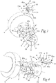
- Figs 1 and 2
- are perspective views of a thread milling tool according to a first embodiment of the present invention,
- Figs 3 and 4
- are perspective views from different directions of a part of the thread milling tool of
Figs 1 and 2 , - Fig 5
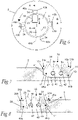
- is a lateral view of the thread milling tool of
Figs 1 and 2 , - Fig 6
- is a front view of the thread milling tool of
Figs 1 and 2 , - Fig 7
- is a cut according to the line A-A in
Fig 6 , - Fig 8
- is a cut according to the line B-B in
Fig 6 , - Figs 9a and 9b
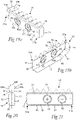
- are perspective views from different directions of a thread milling insert included in the thread milling tool of
Figs 1 and 2 , - Fig 10
- is a rear view of the thread milling insert of
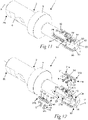
Figs 9a and 9b , - Figs 11 and 12
- are perspective views of a thread milling tool according to a second embodiment of the present invention,
- Figs 13 and 14
- are perspective views from different directions of a part of the thread milling tool of
Figs 11 and 12 , - Fig 15
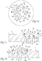
- is a lateral view of the thread milling tool of
Figs 11 and 12 , - Fig 16
- is a front view of the thread milling tool of
Figs 11 and 12 , - Fig 17
- is a cut according to the line C-C in
Fig 16 , - Fig 18
- is a cut according to the line D-D in
Fig 16 , - Figs 19a and 19b
- are perspective views from different directions of a thread milling insert included in the thread milling tool of
Figs 11 and 12 , - Fig 20
- is a rear view of the thread milling insert of
Figs 19a and 19b , and - Fig 21
- is a lateral view of a thread milling insert of an alternative variant.
- Two different embodiments of a
thread milling tool 1 according to the present invention are illustrated inFigs 1-8 and11-18 . Thethread milling tool 1 comprises anelongated tool body 2 and is configured to be rotated about an axis ofrotation 3. Thetool body 2 has afront end 2a and an oppositerear end 2b. Alongitudinal axis 4 of thetool body 2 extends between therear end 2b and thefront end 2a of the tool body, wherein thislongitudinal axis 4 coincides with the axis ofrotation 3 of thethread milling tool 1. In the illustrated embodiments, acollar 5 is provided at the middle of thetool body 2. A rear part of the tool body located between thecollar 5 and therear end 2b forms aconnection member 6, through which thetool body 2 is mountable, directly or via an intermediate tool holder, to a rotating spindle or the similar of a machine, for instance a milling machine or a drilling machine. A front part of thetool body 2 located between thecollar 5 and thefront end 2a is provided withinsert seats thread milling insert 30. The insert seats 10, 20 are arranged in pairs, wherein each pair consists of afirst insert seat 10 located close to thefront end 2a of thetool body 2 and asecond insert seat 20 located further away from thefront end 2a of thetool body 2. Thus, the first and second insert seats 10, 20 are axially offset from each other in the longitudinal direction of thetool body 2 with thefirst insert seat 10 located closer to thefront end 2a of thetool body 2 than thesecond insert seat 20. Furthermore, the first and second insert seats 10, 20 are angularly offset from each other with respect to thelongitudinal axis 4 of thetool body 2. Thefirst insert seat 10 extends in the longitudinal direction of thetool body 2 and has afirst end 10a and an oppositesecond end 10b, wherein thefirst end 10a of the first insert seat is located closer to thefront end 2a of thetool body 2 than thesecond end 10b of the first insert seat. Also thesecond insert seat 20 extends in the longitudinal direction of thetool body 2 in parallel with thefirst insert seat 10 and has afirst end 20a and an oppositesecond end 20b, wherein thefirst end 20a of the second insert seat is located closer to thefront end 2a of thetool body 2 than thesecond end 20b of the second insert seat. - In the embodiment illustrated in
Figs 1-8 , thetool body 2 is provided with two pairs ofinsert seats Figs 11-18 , thetool body 2 is provided with three pairs ofinsert seats tool body 2 may as an alternative, inter alia depending on the diameter of the tool body, be provided with any other suitable number of insert seats. A smaller diameter tool body may for instance be provided with only one pair ofinsert seats insert seats tool body 2 is provided with two or more pairs of insert seats, the first insert seats 10 of the different pairs are mutually located at the same axial position in thetool body 2 and are evenly distributed about thelongitudinal axis 4 of the tool body. In the corresponding manner, the second insert seats 20 of the different pairs are mutually located at the same axial position in thetool body 2 and are evenly distributed about thelongitudinal axis 4 of the tool body. Furthermore, the first and second insert seats 10, 20 are alternately arranged as seen in the circumferential direction of thetool body 2. Thus, when seen in the circumferential direction of thetool body 2, eachfirst insert seat 10 is arranged between two second insert seats 20 and eachsecond insert seat 20 is arranged between two first insert seats. - Each
insert seat thread milling insert 30. The thread milling inserts 30 received in the first and second insert seats 10, 20 are geometrically identical to each other, or at least substantially geometrically identical to each other. Thus, the thread milling inserts 30 included in one and the samethread milling tool 1 all have the same basic shape and are of the same size. The thread milling inserts 30 have the form of double-sided inserts and are detachably mountable in the insert seats 10, 20. - Each
thread milling insert 30 comprises anelongated insert body 31 having afirst end 31a and an oppositesecond end 31b. Theinsert body 31 comprises first and second major faces 32, 33, which are arranged on opposite sides of theinsert body 31 and which serve as top and bottom faces of thethread milling insert 30. The first and second major faces 32, 33 of theinsert body 31 extend between the first andsecond ends insert body 31. A median plane MP, which constitutes an imaginary plane, extends halfway between the first and second major faces 32, 33 of theinsert body 31, as illustrated inFigs 10 and20 . Eachthread milling insert 30 further comprises a plurality ofteeth 34 arranged one after the other in a row along aperipheral side 35 of theinsert body 31 that is located between the first and second major faces 32, 33 and that extends between the first andsecond ends insert body 31. Eachtooth 34 has afirst side surface 37, an oppositesecond side surface 38 and aperipheral surface 39 extending between the first and second side surfaces 37, 38. On eachtooth 34, afirst cutting edge 40a is formed at an intersection between theperipheral surface 39 and thefirst side surface 37 and asecond cutting edge 40b is formed at an intersection between theperipheral surface 39 and thesecond side surface 38. Thefirst cutting edge 40a is arranged on a first side of thetooth 34 facing the firstmajor face 32 of theinsert body 31 and thesecond cutting edge 40b is arranged on an opposite second side of thetooth 34 facing the secondmajor face 33 of thetool body 31. The first andsecond cutting edges peripheral surface 39 and thefirst side surface 37 and thesecond side surface 38, respectively, or at least along a part thereof at the tip of thetooth 34. In the latter case, each one of the first andsecond cutting edges tooth 34 on either side of the tip of the tooth. Thefirst side surface 37 is configured to serve as a rake face for thefirst cutting edge 40a, and thesecond side surface 38 is configured to serve as a rake face for thesecond cutting edge 40b. Theperipheral surface 39 serves as a relief surface for the first andsecond cutting edges Figs 10 and20 . - In the illustrated embodiments, the first and second side surfaces 37, 38 of each
tooth 34 are inclined outwards, at an acute angle α to each other, as seen in a direction from the base of the tooth towards the tip thereof, as illustrated inFigs 10 and20 . - The
first cutting edges 40a of theteeth 34 on each individualthread milling insert 30 form a first group of cutting edges of the thread milling insert and thesecond cutting edges 40b of theteeth 34 form a second group of cutting edges of the thread milling insert. The first group of cuttingedges 40a and the second group of cuttingedges 40b are mirror symmetrical to each other with respect to the median plane MP of theinsert body 31. - Each
thread milling insert 31 is provided with threeteeth 34 in the embodiment illustrated inFigs 1-10 and with seventeeth 34 in the embodiment illustrated inFigs 11-20 . However, the thread milling inserts 31 may be provided with any other suitable number ofteeth 34. - In the illustrated embodiments, the
insert body 31 of eachthread milling insert 30 is provided with a fastening means in the form of two throughholes 42, which extend in parallel with each other through theinsert body 31 between the first and second major faces 32, 33. Each throughhole 42 has a centre axis CA that extends perpendicularly to the first and second major faces 32, 33. Each throughhole 42 is configured to receive afastening element 8, for instance in the form of a screw, by means of which thethread milling insert 30 may be releasably fixed in any of the insert seats 10, 20 in thetool body 2. As an alternative, there could be only one such throughhole 42 or more than two mutually parallel throughholes 42 in theinsert body 31. The thread milling inserts 30 may as a further alternative lack a throughhole 42, wherein eachthread milling insert 30 is configured to be releasably fixed to any of the insert seats in the tool body by means of suitable clamping means. - The
insert body 31 of eachthread milling insert 30 is provided with anaxial abutment surface 41, which is located at thefirst end 31a of theinsert body 31 and which is configured to abut against a correspondingaxial support surface 11 in any of the first insert seats 10 when thethread milling insert 30 is mounted in the first insert seat in question and to abut against a correspondingaxial support surface 21 in any of thesecond insert seat 20 when thethread milling insert 30 is mounted in the second insert seat in question. Thus, each insertseat axial support surface axial abutment surface 41 on theinsert body 31 of athread milling insert 30 when thethread milling insert 30 is mounted in theinsert seat axial support surface 11 in eachfirst insert seat 10 is located at thesecond end 10b of the first insert seat and faces thefront end 2a of thetool body 2, whereas theaxial support surface 21 in eachsecond insert seat 20 is located at thefirst end 20a of the second insert seat and faces therear end 2b of thetool body 2. In this case, the first insert seats 10 may be open towards afront end surface 7 of thetool body 2, i.e. with thefirst end 10a of eachfirst insert seat 10 formed as an opening in saidfront end surface 7. In an alternative embodiment (not shown), theaxial support surface 11 in eachfirst insert seat 10 is located at thefirst end 10a of the first insert seat and faces therear end 2b of thetool body 2, whereas theaxial support surface 21 in eachsecond insert seat 20 is located at thesecond end 20b of the second insert seat and faces thefront end 2a of thetool body 2. - In the illustrated embodiments, the
axial abutment surface 41 on theinsert body 31 of eachthread milling insert 30 is formed by an end surface on theinsert body 31 at thefirst end 31a thereof. Theaxial abutment surface 41 is preferably a plane surface that extends perpendicularly to the median plane MP of theinsert body 31, wherein theaxial support surface seat longitudinal axis 4 of thetool body 2. However, theaxial abutment surface 41 and the axial support surfaces 11, 21 may also have any other suitable and mutually matching shapes. - The
insert body 31 of eachthread milling insert 30 is also provided with aradial abutment surface 43 formed on aperipheral side 45 of the insert body opposite to theperipheral side 35 provided with theteeth 34, wherein thisradial abutment surface 43 is configured to abut against a correspondingradial support surface 13 in any of the first insert seats 10 when thethread milling insert 30 is mounted in the first insert seat in question and to abut against a correspondingradial support surface 23 in any of thesecond insert seat 20 when thethread milling insert 30 is mounted in the second insert seat in question. Theradial abutment surface 43 is preferably perpendicular to theaxial abutment surface 41. Thus, each insertseat radial support surface radial abutment surface 43 on theinsert body 31 of athread milling insert 30 when thethread milling insert 30 is mounted in theinsert seat radial support surface axial support surface - In the illustrated embodiments, each
thread milling insert 30 is configured to be releasably fixed to any of the insert seats 10, 20 in thetool body 2 by means of twofastening elements 8 in the form of screws, which extend through a respective one of the throughholes 42 in theinsert body 31 of the thread milling insert and is engaged in a threadedhole 12, 22 (seeFigs 2-4 and12-14 ) in atangential support surface fastening element 8 comprises anelongated shaft 8a, which is provided with an external thread configured for engagement with a corresponding internal thread in any of said threadedholes head 8b, which is fixed to theshaft 8a. Theshaft 8a has an external diameter that is smaller than the internal diameter of the throughholes 42 in theinsert body 31 such that theshaft 8a is receivable with play in any of the throughholes 42, as illustrated inFigs 7, 8 ,17 and 18 . Each throughhole 42 is provided with a conically shapedinternal surface 42a at each of its ends configured for engagement with a corresponding conically shapedexternal surface 8c on thehead 8b of each fastening element. When afastening element 8 is threaded into one of the threadedholes shaft 8a of thefastening element 8 received in one of the throughholes 42 in theinsert body 31 of athread milling insert 30 positioned in the insert seat in question, the conically shapedexternal surface 8c on thehead 8b will come into engagement with one of the conically shapedinternal surfaces 42a in the throughhole 42 and thereby push theinsert body 31 against theaxial support surface - According to the invention, the thread milling inserts 30 are so adapted to the first and second insert seats 10, 20 that each
thread milling insert 30 is: - mountable in any of the first insert seats 10 in one single working position with the
axial abutment surface 41 on theinsert body 31 of the thread milling insert abutting against theaxial support surface 11 in thefirst insert seat 10 in question and with one of the first and second groups of cuttingedges - mountable in any of the second insert seats 20 in one single working position with the
axial abutment surface 41 on theinsert body 31 of the thread milling insert abutting against theaxial support surface 21 in thesecond insert seat 20 in question and with the other one of said first and second groups of cuttingedges - In the illustrated embodiments:
- the first group of cutting
edges 40a of athread milling insert 30 is always in the active cutting position when the thread milling insert is mounted in one of the first insert seats 10, wherein the secondmajor face 33 of theinsert body 31, or at least a portion thereof, abuts against thetangential support surface 13 in theinsert seat 10 in question; and - the second group of cutting
edges 40b of athread milling insert 30 is always in the active cutting position when the thread milling insert is mounted in one of the second insert seats 20, wherein the firstmajor face 32 of theinsert body 31, or at least a portion thereof, abuts against thetangential support surface 23 in theinsert seat 20 in question. - In the embodiments illustrated in
Figs 1-20 , the shape of theinsert body 31 of eachthread milling insert 30 is so adapted to the shape of the first and second insert seats 10, 20 that theinsert body 31 fits into any of the first insert seats 10 only in a position with theaxial abutment surface 41 on theinsert body 31 abutting against theaxial support surface 11 in thefirst insert seat 10 and into any of the second insert seats 20 only in a position with theaxial abutment surface 41 on theinsert body 31 abutting against theaxial support surface 21 in thesecond insert seat 20. - In the embodiments illustrated in
Figs 1-20 , theinsert body 31 of eachthread milling insert 30 has afirst end section 46a at itsfirst end 31a with a shape that differs from the shape of a correspondingsecond end section 46b at its oppositesecond end 31b. In order to ensure a correct mounting of the thread milling inserts 30 in the insert seats 10, 20, each one of the first andsecond insert seat first end section Figs 3, 4 ,13 and 14 ) at one 10b, 20a of its ends with a shape adapted to the shape of thefirst end section 46a of theinsert body 31 of eachthread milling insert 30 and a differently shapedsecond end section Figs 3, 4 ,13 and 14 ) at itsother end second end section 46b of theinsert body 31 of eachthread milling insert 30. - In the embodiments illustrated in
Figs 1-20 , the above-mentionedfirst end section 46a of theinsert body 31 comprises an inclinedperipheral side surface 47, which forms a connection between the axial and radial abutment surfaces 41, 43 on theinsert body 31 and which is configured to face a correspondinginclined surface first end section thread milling insert 30 is mounted in the insert seat in question. The oppositesecond end section 46b of theinsert body 31 lacks such an inclined peripheral side surface to thereby prevent thesecond end section 46b of theinsert body 31 to fit into thefirst end section inclined surfaces first end section second end section 46b of theinsert body 31, will prevent thethread milling insert 31 from being mounted in any of the insert seats 10, 20 with thesecond end 31b of the insert body facing theaxial support surface - In the embodiment illustrated in
Fig 21 , the first andsecond ends insert body 31 of thethread milling insert 30 have the same shape. In this case, the positions of the throughholes 42 in theinsert body 31 have been moved towards thesecond end 31b of the insert body, as compared to the symmetric arrangement of the throughholes 42 in theinsert body 31 in the embodiments illustrated inFigs 1-20 . In the embodiment illustrated inFig 21 , the asymmetric arrangement of the throughholes 42 in theinsert body 31 and a corresponding arrangement of the threadedholes thread milling insert 30 can only be mounted in one single working position in each insertseat - In the illustrated embodiments, the
insert body 31 of eachthread milling insert 30 has: - mirror symmetry with respect to the median plane MP of the
insert body 31, - mirror asymmetry with respect to any other plane across the
insert body 31, and - rotational asymmetry with respect to any axis across the
insert body 31. - In the embodiment illustrated in
Figs 1-8 , the first and second insert seats 10, 20 have such axial positions in relation to each other in thetool body 2 that the axial distance between thetooth 34 closest to thesecond end 10b of afirst insert seat 10 on athread milling insert 30 mounted in any of the first insert seats 10 and thetooth 34 closest to thefirst end 20a of an adjacentsecond insert seat 20 on athread milling insert 30 mounted in thissecond insert seat 20 is substantially equal to the axial distance between twoadjacent teeth 34 on any of these thread milling inserts. - In the embodiment illustrated in
Figs 11-18 , the first and second insert seats 10, 20 have such axial positions in relation to each other in thetool body 2 that thetooth 34 closest to thesecond end 10b of afirst insert seat 10 on athread milling insert 30 mounted in any of the first insert seats 10 and thetooth 34 closest to thefirst end 20a of an adjacentsecond insert seat 20 on athread milling insert 30 mounted in thissecond insert seat 20 are located at the same axial position in thetool body 2 and thereby overlap each other, as seen in the longitudinal direction of thetool body 2. - The invention is of course not in any way restricted to the embodiments described above. On the contrary, many possibilities to modifications thereof will be apparent to a person with ordinary skill in the art without departing from the basic idea of the invention such as defined in the appended claims.
Claims (15)
- A thread milling tool comprising:- an elongated tool body (2) having a front end (2a) and an opposite rear end (2b), the rear end (2b) being configured for attachment to a machine, wherein a longitudinal axis (4) of the tool body (2) extends between the rear end (2b) and the front end (2a) of the tool body;- at least one pair of insert seats (10, 20) provided in the tool body (2) and consisting of a first insert seat (10) and a second insert seat (20), the first and second inserts seats (10, 20) being angularly offset from each other with respect to the longitudinal axis (4) of the tool body (2) and axially offset from each other in the longitudinal direction of the tool body (2) with the first insert seat (10) located closer to the front end (2a) of the tool body (2) than the second insert seat (20), wherein each one of the first and second insert seats (10, 20) has a first end (10a, 20a) and an opposite second end (10b, 20b), the first end (10a, 20a) of each one of the first and second insert seats (10, 20) being arranged closer to the front end (2a) of the tool body (2) than the opposite second end (10b, 20b) of the same insert seat; and- several substantially geometrically identical thread milling inserts (30), each of which being detachably mountable in a respective insert seat (10, 20) of the at least one pair of insert seats (10, 20) and comprising:• an elongated insert body (31) having a first end (31a) and an opposite second end (31b), wherein the insert body (31) comprises first and second major faces (32, 33) arranged on opposite sides of the insert body and serving as top and bottom faces of the thread milling insert, and wherein the insert body (31) is provided with an axial abutment surface (41), which is located at the first end (31a) of the insert body (31) and which is configured to abut against a corresponding axial support surface (11) in the first insert seat (10) when the thread milling insert (30) is mounted in the first insert seat and to abut against a corresponding axial support surface (21) in the second insert seat (20) when the thread milling insert (30) is mounted in the second insert seat, and• a plurality of teeth (34) arranged one after the other in a row along a peripheral side (35) of the insert body (31) that is located between the first and second major faces (32, 33) and that extends between the first and second ends (31a, 31b) of the insert body (31), wherein each tooth (34) of the plurality of teeth (34) has a first cutting edge (40a) on a first side of the tooth facing the first major face (32) and a second cutting edge (40b) on an opposite second side of the tooth facing the second major face (33), the first cutting edges (40a) of the plurality of teeth (34) forming a first group of cutting edges and the second cutting edges (40b) of the plurality of teeth (34) forming a second group of cutting edges, wherein the first group of cutting edges (40a) and the second group of cutting edges (40b) are mirror symmetrical to each other with respect to a median plane (MP) of the insert body (31) that extends halfway between the first and second major faces (32, 33) of the insert body (31) characterized in:- that the axial support surfaces (11, 21) in the first and second insert seats (10, 20) of said at least one pair of insert seats are arranged:• with the axial support surface (11) in the first insert seat (10) located at the second end (10b) of the first insert seat and facing the front end (2a) of the tool body (2), and the axial support surface (21) in the second insert seat (20) located at the first end (20a) of the second insert seat and facing the rear end (2b) of the tool body (2), or• with the axial support surface (11) in the first insert seat (10) located at the first end (10a) of the first insert seat and facing the rear end (2b) of the tool body (2), and the axial support surface (21) in the second insert seat (20) located at the second end (20b) of the second insert seat and facing the front end (2a) of the tool body (2); and- that each one of the thread milling inserts (30) is adapted to the first and second insert seats (10, 20) of said at least one pair of insert seats such that the thread milling insert (30) is:• mountable in the first insert seat (10) in one single working position with the axial abutment surface (41) on the insert body (31) of the thread milling insert abutting against the axial support surface (11) in the first insert seat (10) and with one of said first and second groups of cutting edges (40a, 40b) in an active cutting position, and• mountable in the second insert seat (20) in one single working position with the axial abutment surface (41) on the insert body (31) of the thread milling insert abutting against the axial support surface (21) in the second insert seat (20) and with the other one of said first and second groups of cutting edges (40a, 40b) in an active cutting position.
- A thread milling tool according to claim 1, characterized in that the insert body (31) of each one of the thread milling inserts has:- mirror symmetry with respect to the median plane (MP) of the insert body (31),- mirror asymmetry with respect to any other plane across the insert body (31), and- rotational asymmetry with respect to any axis across the insert body (31).
- A thread milling tool according to claim 1 or 2, characterized in that the shape of the insert body (31) of each one of the thread milling inserts (30) is so adapted to the shape of the first and second insert seats (10, 20) of said at least one pair of insert seats that the insert body (31) fits into the first insert seat (10) only in a position with the axial abutment surface (41) on the insert body (31) abutting against the axial support surface (11) in the first insert seat (10) and into the second insert seat (20) only in a position with the axial abutment surface (41) on the insert body (31) abutting against the axial support surface (21) in the second insert seat (20).
- A thread milling tool according to claim 3, characterized in that the insert body (31) of each one of the thread milling inserts (30) has an end section (46a) at its first end (31a) with a shape that differs from the shape of a corresponding end section (46b) at its second end (31b).
- A thread milling tool according to any of claims 1-4, characterized in that the axial abutment surface (41) on the insert body (31) of each one of the thread milling inserts (30) is formed by an end surface on the insert body (31) at the first end (31a) thereof.
- A thread milling tool according to claim 5, characterized in that the insert body (31) of each one of the thread milling inserts (30) is provided with:- a radial abutment surface (43), which is formed on a peripheral side (45) of the insert body opposite to the peripheral side (35) provided with said teeth (34) and which is configured to abut against a corresponding radial support surface (13, 23) in any of the first and second insert seats (10, 20) when the thread milling insert (30) is mounted in the insert seat in question; and- an inclined peripheral side surface (47), which forms a connection between the axial and radial abutment surfaces (41, 43) on the insert body (31) and which is configured to face a corresponding inclined surface (17, 27) in any of the first and second insert seats (10, 20) when the thread milling insert (30) is mounted in the insert seat in question.
- A thread milling tool according to any of claims 1-6, characterized in that said plurality of teeth (34) are at least three in number.
- A thread milling tool according to any of claims 1-7, characterized in that the first and second insert seats (10, 20) of said at least one pair of insert seats have such axial positions in relation to each other in the tool body (2) that the axial distance between the tooth (34) closest to the second end (10b) of the first insert seat (10) on a thread milling insert (30) mounted in the first insert seat (10) and the tooth (34) closest to the first end (20a) of the second insert seat (20) on a thread milling insert (30) mounted in the second insert seat (20) is substantially equal to the axial distance between two adjacent teeth (34) on any of these thread milling inserts.
- A thread milling tool according to any of claims 1-7, characterized in that the first and second insert seats (10, 20) of said at least one pair of insert seats have such axial positions in relation to each other in the tool body (2) that the tooth (34) closest to the second end (10b) of the first insert seat (10) on a thread milling insert (30) mounted in the first insert seat (10) and the tooth (34) closest to the first end (20a) of the second insert seat (20) on a thread milling insert (30) mounted in the second insert seat (20) are located at the same axial position in the tool body (2) and thereby overlap each other in the longitudinal direction of the tool body.
- A thread milling tool according to any of claims 1-9, characterized in that two or more such pairs of insert seats (10, 20) are provided in the tool body (2), wherein the first insert seats (10) of the different pairs of insert seats are located at the same axial position in the tool body (2) and are evenly distributed about the longitudinal axis (4) of the tool body, and wherein the second insert seats (20) of the different pairs of insert seats are located at the same axial position in the tool body (2) and are evenly distributed about the longitudinal axis (4) of the tool body.
- A thread milling insert for use in a thread milling tool, the thread milling insert (30) comprising:- an elongated insert body (31) having a first end (31a) and an opposite second end (31b), wherein the insert body (31) comprises first and second major faces (32, 33) arranged on opposite sides of the insert body and serving as top and bottom faces of the thread milling insert, and wherein the insert body (31) is provided with an axial abutment surface (41), which is located at the first end (31a) of the insert body (31) and which is configured to abut against a corresponding axial support surface (11, 21) in an insert seat (10, 20) in the thread milling tool when the thread milling insert (30) is mounted in the insert seat; and- a plurality of teeth (34) arranged one after the other in a row along a peripheral side (35) of the insert body (31) that is located between the first and second major faces (32, 33) and that extends between the first and second ends (31a, 31b) of the insert body (31), each tooth (34) having a first cutting edge (40a) on a first side of the tooth facing the first major face (32) and a second cutting edge (40b) on an opposite second side of the tooth facing the second major face (33), wherein the first and second cutting edges (40a, 40b) on each tooth (34) are mirror symmetrical to each other with respect to a median plane (MP) of the insert body (31) that extends halfway between the first and second major faces (32, 33) of the insert body, characterized in that the insert body (31) has:- mirror symmetry with respect to the median plane (MP) of the insert body (31),- mirror asymmetry with respect to any other plane across the insert body (31), and - rotational asymmetry with respect to any axis across the insert body (31).
- A thread milling insert according to claim 11, characterized in that the insert body (31) has an end section (46a) at its first end (31a) with a shape that differs from the shape of a corresponding end section (46b) at the second end (31b) of the insert body.
- A thread milling insert according to claim 11 or 12, characterized in that the axial abutment surface (41) on the insert body (31) is formed by an end surface on the insert body (31) at the first end (31a) thereof.
- A thread milling insert according to claim 13, characterized in that the insert body (31) is provided with:- a radial abutment surface (43), which is formed on a peripheral side (45) of the insert body opposite to the peripheral side (35) provided with said teeth (34) and which is configured to abut against a corresponding radial support surface (13, 23) in an insert seat (10, 20) in the thread milling tool when the thread milling insert (30) is mounted in the insert seat; and- an inclined peripheral side surface (47), which forms a connection between the axial and radial abutment surfaces (41, 43) on the insert body (31).
- A thread milling insert according to any of claims 11-14, characterized in that said plurality of teeth (34) are at least three in number.
Priority Applications (5)
| Application Number | Priority Date | Filing Date | Title |
|---|---|---|---|
| EP20211239.7A EP4008468A1 (en) | 2020-12-02 | 2020-12-02 | Thread milling tool and thread milling insert |
| CN202180079648.0A CN116529010B (en) | 2020-12-02 | 2021-11-22 | Thread milling tools and thread milling inserts |
| US18/039,855 US20240001466A1 (en) | 2020-12-02 | 2021-11-22 | Thread milling tool and thread milling insert |
| PCT/EP2021/082402 WO2022117375A1 (en) | 2020-12-02 | 2021-11-22 | Thread milling tool and thread milling insert |
| KR1020237020873A KR20230110576A (en) | 2020-12-02 | 2021-11-22 | Thread milling tools and thread milling inserts |
Applications Claiming Priority (1)
| Application Number | Priority Date | Filing Date | Title |
|---|---|---|---|
| EP20211239.7A EP4008468A1 (en) | 2020-12-02 | 2020-12-02 | Thread milling tool and thread milling insert |
Publications (1)
| Publication Number | Publication Date |
|---|---|
| EP4008468A1 true EP4008468A1 (en) | 2022-06-08 |
Family
ID=73694841
Family Applications (1)
| Application Number | Title | Priority Date | Filing Date |
|---|---|---|---|
| EP20211239.7A Pending EP4008468A1 (en) | 2020-12-02 | 2020-12-02 | Thread milling tool and thread milling insert |
Country Status (5)
| Country | Link |
|---|---|
| US (1) | US20240001466A1 (en) |
| EP (1) | EP4008468A1 (en) |
| KR (1) | KR20230110576A (en) |
| CN (1) | CN116529010B (en) |
| WO (1) | WO2022117375A1 (en) |
Cited By (1)
| Publication number | Priority date | Publication date | Assignee | Title |
|---|---|---|---|---|
| US20250073796A1 (en) * | 2023-09-05 | 2025-03-06 | Iscar, Ltd. | Thread milling tool and method for machining threads |
Citations (5)
| Publication number | Priority date | Publication date | Assignee | Title |
|---|---|---|---|---|
| US20010018010A1 (en) * | 1999-12-04 | 2001-08-30 | Michael Kichin | Milling tool and insert, particularly thread milling cutter |
| EP1198321B1 (en) | 1999-06-29 | 2005-08-17 | SECO TOOLS AB (publ) | Thread-milling cutter and a thread-milling insert |
| WO2005080038A1 (en) * | 2004-02-20 | 2005-09-01 | Sandvik Intellectual Property Ab | Slot milling cutter |
| WO2010101512A2 (en) | 2009-03-04 | 2010-09-10 | Seco Tools Ab | Method of thread milling, thread, and insert and tool for thread milling |
| EP2420340A1 (en) * | 2010-08-20 | 2012-02-22 | VARGUS Ltd. | Thread-milling cutter and thread-milling insert |
Family Cites Families (10)
| Publication number | Priority date | Publication date | Assignee | Title |
|---|---|---|---|---|
| US5873684A (en) * | 1997-03-29 | 1999-02-23 | Tool Flo Manufacturing, Inc. | Thread mill having multiple thread cutters |
| DE102004043409A1 (en) * | 2004-09-02 | 2006-03-09 | Vargus Ltd. | Milling tool, in particular thread milling cutter |
| DE102006024131A1 (en) * | 2006-05-22 | 2007-11-29 | Sandvik Intellectual Property Ab | Cutting insert with plane cutting edge, especially for face milling cutters |
| SE531858C2 (en) * | 2007-12-21 | 2009-08-25 | Sandvik Intellectual Property | Milling tools for chip separating machining, as well as cutting body and basic body for this |
| DE102009038133A1 (en) * | 2009-08-13 | 2011-02-17 | Komet Group Gmbh | Milling tool, in particular thread milling tool |
| EP2433730A1 (en) * | 2010-09-23 | 2012-03-28 | Johs. Boss GmbH & Co. KG | Device for machining a profile and machining tool therefor |
| CN104741665A (en) * | 2015-03-20 | 2015-07-01 | 山西风雷钻具有限公司 | Mechanical-clamping non-indexable inner embedded knife tool |
| CN205237252U (en) * | 2015-12-28 | 2016-05-18 | 台州中天工具有限公司 | Thread fraise in split type |
| US11413696B2 (en) * | 2019-01-17 | 2022-08-16 | Tungaloy Corporation | Indexable cutting tool |
| CN209716694U (en) * | 2019-04-22 | 2019-12-03 | 东莞市朗赛德五金工具有限公司 | A portable thread milling cutter |
-
2020
- 2020-12-02 EP EP20211239.7A patent/EP4008468A1/en active Pending
-
2021
- 2021-11-22 WO PCT/EP2021/082402 patent/WO2022117375A1/en not_active Ceased
- 2021-11-22 KR KR1020237020873A patent/KR20230110576A/en active Pending
- 2021-11-22 CN CN202180079648.0A patent/CN116529010B/en active Active
- 2021-11-22 US US18/039,855 patent/US20240001466A1/en active Pending
Patent Citations (5)
| Publication number | Priority date | Publication date | Assignee | Title |
|---|---|---|---|---|
| EP1198321B1 (en) | 1999-06-29 | 2005-08-17 | SECO TOOLS AB (publ) | Thread-milling cutter and a thread-milling insert |
| US20010018010A1 (en) * | 1999-12-04 | 2001-08-30 | Michael Kichin | Milling tool and insert, particularly thread milling cutter |
| WO2005080038A1 (en) * | 2004-02-20 | 2005-09-01 | Sandvik Intellectual Property Ab | Slot milling cutter |
| WO2010101512A2 (en) | 2009-03-04 | 2010-09-10 | Seco Tools Ab | Method of thread milling, thread, and insert and tool for thread milling |
| EP2420340A1 (en) * | 2010-08-20 | 2012-02-22 | VARGUS Ltd. | Thread-milling cutter and thread-milling insert |
Cited By (1)
| Publication number | Priority date | Publication date | Assignee | Title |
|---|---|---|---|---|
| US20250073796A1 (en) * | 2023-09-05 | 2025-03-06 | Iscar, Ltd. | Thread milling tool and method for machining threads |
Also Published As
| Publication number | Publication date |
|---|---|
| WO2022117375A1 (en) | 2022-06-09 |
| US20240001466A1 (en) | 2024-01-04 |
| CN116529010B (en) | 2025-07-15 |
| KR20230110576A (en) | 2023-07-24 |
| CN116529010A (en) | 2023-08-01 |
Similar Documents
| Publication | Publication Date | Title |
|---|---|---|
| EP2664399B1 (en) | Cutting tool | |
| US6616387B2 (en) | Metal cutting tool with direct cutting plate arrangement | |
| JP6532940B2 (en) | Double-sided cutting inserts and milling tools | |
| EP2489454A1 (en) | Cutting insert and rotary tool with a replaceable blade edge | |
| EP3088112B1 (en) | Replaceable blade edge rotary cutting tool and tool body | |
| AU580779B2 (en) | Conical cutting insert | |
| WO2013004568A1 (en) | Milling tool with recessed cutting edge | |
| WO2008067634A1 (en) | Cup mill for airfoils | |
| EP3147057B1 (en) | Indexable rotary cutting tool | |
| US20230373020A1 (en) | Double-sided cutting insert and milling tool | |
| CN102143816A (en) | Side cutter | |
| KR20170015925A (en) | Thread milling cutter | |
| US20240001466A1 (en) | Thread milling tool and thread milling insert | |
| KR20080026027A (en) | Screw turning tools | |
| EP2764938A1 (en) | Device for chip removing machining | |
| JP7811592B2 (en) | Metal Cutting Milling Tools | |
| US6431799B1 (en) | Slotting cutter | |
| US7510353B2 (en) | Indexable cutting tool insert and cutting tool | |
| US6497537B1 (en) | Slotting cutter with cartridge assembly | |
| US20040253063A1 (en) | Cutting tool insert and cutter body | |
| US20250050428A1 (en) | Double-sided tangential cutting insert | |
| JP2008023632A (en) | Cutting tools and inserts | |
| EP4491310B1 (en) | Face milling cutter | |
| EP4706856A1 (en) | Cutting tool | |
| CN114799366B (en) | Embedded high-order precision full-transposition internal cooling gear hob |
Legal Events
| Date | Code | Title | Description |
|---|---|---|---|
| PUAI | Public reference made under article 153(3) epc to a published international application that has entered the european phase |
Free format text: ORIGINAL CODE: 0009012 |
|
| STAA | Information on the status of an ep patent application or granted ep patent |
Free format text: STATUS: THE APPLICATION HAS BEEN PUBLISHED |
|
| AK | Designated contracting states |
Kind code of ref document: A1 Designated state(s): AL AT BE BG CH CY CZ DE DK EE ES FI FR GB GR HR HU IE IS IT LI LT LU LV MC MK MT NL NO PL PT RO RS SE SI SK SM TR |
|
| STAA | Information on the status of an ep patent application or granted ep patent |
Free format text: STATUS: REQUEST FOR EXAMINATION WAS MADE |
|
| 17P | Request for examination filed |
Effective date: 20221208 |
|
| RBV | Designated contracting states (corrected) |
Designated state(s): AL AT BE BG CH CY CZ DE DK EE ES FI FR GB GR HR HU IE IS IT LI LT LU LV MC MK MT NL NO PL PT RO RS SE SI SK SM TR |