EP4008433A1 - Diagnostics laboratory distribution system - Google Patents
Diagnostics laboratory distribution system Download PDFInfo
- Publication number
- EP4008433A1 EP4008433A1 EP20383055.9A EP20383055A EP4008433A1 EP 4008433 A1 EP4008433 A1 EP 4008433A1 EP 20383055 A EP20383055 A EP 20383055A EP 4008433 A1 EP4008433 A1 EP 4008433A1
- Authority
- EP
- European Patent Office
- Prior art keywords
- distribution system
- control device
- generating devices
- transport plane
- microbiological
- Prior art date
- Legal status (The legal status is an assumption and is not a legal conclusion. Google has not performed a legal analysis and makes no representation as to the accuracy of the status listed.)
- Granted
Links
Images


Classifications
-
- B—PERFORMING OPERATIONS; TRANSPORTING
- B01—PHYSICAL OR CHEMICAL PROCESSES OR APPARATUS IN GENERAL
- B01L—CHEMICAL OR PHYSICAL LABORATORY APPARATUS FOR GENERAL USE
- B01L1/00—Enclosures; Chambers
- B01L1/02—Air-pressure chambers; Air-locks therefor
- B01L1/025—Environmental chambers
-
- G—PHYSICS
- G01—MEASURING; TESTING
- G01N—INVESTIGATING OR ANALYSING MATERIALS BY DETERMINING THEIR CHEMICAL OR PHYSICAL PROPERTIES
- G01N35/00—Automatic analysis not limited to methods or materials provided for in any single one of groups G01N1/00 - G01N33/00; Handling materials therefor
- G01N35/02—Automatic analysis not limited to methods or materials provided for in any single one of groups G01N1/00 - G01N33/00; Handling materials therefor using a plurality of sample containers moved by a conveyor system past one or more treatment or analysis stations
- G01N35/04—Details of the conveyor system
-
- G—PHYSICS
- G01—MEASURING; TESTING
- G01N—INVESTIGATING OR ANALYSING MATERIALS BY DETERMINING THEIR CHEMICAL OR PHYSICAL PROPERTIES
- G01N35/00—Automatic analysis not limited to methods or materials provided for in any single one of groups G01N1/00 - G01N33/00; Handling materials therefor
- G01N35/10—Devices for transferring samples or any liquids to, in, or from, the analysis apparatus, e.g. suction devices, injection devices
- G01N35/1065—Multiple transfer devices
- G01N35/1067—Multiple transfer devices for transfer to or from containers having different spacing
-
- G—PHYSICS
- G01—MEASURING; TESTING
- G01N—INVESTIGATING OR ANALYSING MATERIALS BY DETERMINING THEIR CHEMICAL OR PHYSICAL PROPERTIES
- G01N35/00—Automatic analysis not limited to methods or materials provided for in any single one of groups G01N1/00 - G01N33/00; Handling materials therefor
-
- G—PHYSICS
- G01—MEASURING; TESTING
- G01N—INVESTIGATING OR ANALYSING MATERIALS BY DETERMINING THEIR CHEMICAL OR PHYSICAL PROPERTIES
- G01N35/00—Automatic analysis not limited to methods or materials provided for in any single one of groups G01N1/00 - G01N33/00; Handling materials therefor
- G01N35/02—Automatic analysis not limited to methods or materials provided for in any single one of groups G01N1/00 - G01N33/00; Handling materials therefor using a plurality of sample containers moved by a conveyor system past one or more treatment or analysis stations
-
- G—PHYSICS
- G01—MEASURING; TESTING
- G01N—INVESTIGATING OR ANALYSING MATERIALS BY DETERMINING THEIR CHEMICAL OR PHYSICAL PROPERTIES
- G01N35/00—Automatic analysis not limited to methods or materials provided for in any single one of groups G01N1/00 - G01N33/00; Handling materials therefor
- G01N35/10—Devices for transferring samples or any liquids to, in, or from, the analysis apparatus, e.g. suction devices, injection devices
-
- G—PHYSICS
- G01—MEASURING; TESTING
- G01N—INVESTIGATING OR ANALYSING MATERIALS BY DETERMINING THEIR CHEMICAL OR PHYSICAL PROPERTIES
- G01N35/00—Automatic analysis not limited to methods or materials provided for in any single one of groups G01N1/00 - G01N33/00; Handling materials therefor
- G01N2035/00178—Special arrangements of analysers
- G01N2035/00277—Special precautions to avoid contamination (e.g. enclosures, glove- boxes, sealed sample carriers, disposal of contaminated material)
-
- G—PHYSICS
- G01—MEASURING; TESTING
- G01N—INVESTIGATING OR ANALYSING MATERIALS BY DETERMINING THEIR CHEMICAL OR PHYSICAL PROPERTIES
- G01N35/00—Automatic analysis not limited to methods or materials provided for in any single one of groups G01N1/00 - G01N33/00; Handling materials therefor
- G01N2035/00178—Special arrangements of analysers
- G01N2035/00306—Housings, cabinets, control panels (details)
-
- G—PHYSICS
- G01—MEASURING; TESTING
- G01N—INVESTIGATING OR ANALYSING MATERIALS BY DETERMINING THEIR CHEMICAL OR PHYSICAL PROPERTIES
- G01N35/00—Automatic analysis not limited to methods or materials provided for in any single one of groups G01N1/00 - G01N33/00; Handling materials therefor
- G01N2035/00346—Heating or cooling arrangements
-
- G—PHYSICS
- G01—MEASURING; TESTING
- G01N—INVESTIGATING OR ANALYSING MATERIALS BY DETERMINING THEIR CHEMICAL OR PHYSICAL PROPERTIES
- G01N35/00—Automatic analysis not limited to methods or materials provided for in any single one of groups G01N1/00 - G01N33/00; Handling materials therefor
- G01N2035/00346—Heating or cooling arrangements
- G01N2035/00455—Controlling humidity in analyser
-
- G—PHYSICS
- G01—MEASURING; TESTING
- G01N—INVESTIGATING OR ANALYSING MATERIALS BY DETERMINING THEIR CHEMICAL OR PHYSICAL PROPERTIES
- G01N35/00—Automatic analysis not limited to methods or materials provided for in any single one of groups G01N1/00 - G01N33/00; Handling materials therefor
- G01N35/02—Automatic analysis not limited to methods or materials provided for in any single one of groups G01N1/00 - G01N33/00; Handling materials therefor using a plurality of sample containers moved by a conveyor system past one or more treatment or analysis stations
- G01N35/04—Details of the conveyor system
- G01N2035/0401—Sample carriers, cuvettes or reaction vessels
- G01N2035/0403—Sample carriers with closing or sealing means
- G01N2035/0405—Sample carriers with closing or sealing means manipulating closing or opening means, e.g. stoppers, screw caps, lids or covers
Definitions
- Embodiments of the invention refer to a diagnostics laboratory distribution system.
- Diagnostics laboratory distribution system are described in e.g. EP 3 095 739 A1 or WO2012/158541 . These publications describe laboratory sample distribution systems with passive carriers or self-propelling carriers on transport planes.
- a distribution system is any kind of probe transportation in a diagnostics laboratory within and in-between any analyzers, pre-analytic system, post analytic systems, storage devices etc..
- An object of the invention is to make a diagnostics laboratory distribution system more reliable and safer.
- a first aspect of the present invention concerns a diagnostics laboratory distribution system, wherein the distribution system comprises a number of carriers wherein the carriers are adapted to carry one or more goods.
- Goods can be anything to be distributed in a diagnostics laboratory, e.g. sample tubes, reagent containers, pipetting tips, other consumable material, quality control samples, waste in any form etc..
- a transport plane of the distribution system is adapted to support the carriers.
- Drive means of the distribution system are adapted to move the carriers on the transport plane.
- Drive means can be realized e.g. as magnetic coils underneath the transport plane in connection with a magnetic device in the carriers or as electrical motors in the carriers itself connected to wheels of the carriers.
- a control device of the distribution system controls the drive means.
- the control device is e.g. realized as a central or distributed computing device connected to the drivers of the coils underneath the transport plane or as a distributed control device in the carrier to control the electrical motor of the carrier.
- the distribution system comprises a cover for the transport plane.
- the distribution system comprises humidity sensors connected to the control device and an airflow generating device connected to the control device. The humidity sensors measures the humidity of the air between the cover and the transport plane.
- the airflow generating devices are distributed over the distribution system to generate an airflow between the cover and the transport plane, wherein the control device is configured to start the airflow generating devices if the humidity sensors measure a humidity above a pre-defined threshold value.
- Airflow generating devices can be one single device or multiple devices depending on the geometry of the transport plane layout. For instance a single straight forward pathway only need one airflow generating devices wherein a complex design with multiple crossings and branchings need more than one airflow generating device.
- the pre-defined humidity threshold depends on the goods to be transported.
- thresholds are used well below the dew-point in the range of 60%-90% relative humidity, in particular 70%-80% or 75% relative humidity.
- control device is configured to stop the airflow generating devices, if the humidity sensors measure a humidity value below the pre-defined threshold.
- a further aspect of the inventive distribution system is that the airflow generating devices generates a laminar airflow.
- a laminar flow means that the air particles follow smooth paths in layers.
- the humidity sensor are distributed over the distribution system to control humidity above the transport plane. The distribution is such that in all areas the humidity of the air is measured.
- the humidity sensors work continuously.
- the humidity sensors are adapted to measure the humidity, if a carrier is in the sensor range of the respective humidity sensor.
- Another aspect of the invention is a distribution system wherein the transport plane of the distribution system is arranged in lanes and crossings, wherein the cover of the distribution system comprises negative pressure escape apertures, wherein the negative pressure escape apertures are placed surrounding or at the crossings, so that the laminar airflow is maintained at the crossings.
- the negative pressure escape apertures are placed in pairs at opposite sides of the crossings.
- a further aspect of the inventive distribution system is that the cover comprises heating elements to heat the cover; wherein the control device is connected to the heating elements, wherein the control device is configured to start and stop the heating elements depending on a predefined second threshold of the signals of the humidity sensors.
- the pre-defined second threshold of the signals of the humidity sensors are used below the dew-point in the range of 70%-99% relative humidity, in particular 80%-90% or 95% relative humidity.
- the pre-defined second threshold is higher than the pre-defined threshold measured in relative humidity.
- Another aspect of the invention is a distribution system, wherein the distribution system comprises microbiological sensors, which are arranged between the transport plane and the cover and are connected to the control device and wherein the control device is configured to start the airflow generating devices if the control device receives from the microbiological sensor a signal above a predefined biological threshold.
- the distribution system comprises microbiological sensors, which are arranged between the transport plane and the cover and are connected to the control device and wherein the control device is configured to start the airflow generating devices if the control device receives from the microbiological sensor a signal above a predefined biological threshold.
- control device is configured to stop the airflow generating devices if the signals of the microbiological sensor are below the predefined biological threshold.
- the threshold value depends on the sensor used. Examples of microbiological sensors a real time bio aerosol sensors such as described in US20170209860 .
- Another aspect of the invention is a distribution system, wherein the distribution system comprises an uv-light generating device.
- the uv-light generating devices can be realized as one or more off light bulbs, LEDs, lasers, LED-lasers and so on.
- UV-light as in particular a wavelength between 100 and 400 nm or 200 to 300 nm.
- control devices is connected to the uv-light generating device and starts the uv-light generating device when the signal of the microbiological sensors is above a second pre-defined biological threshold and in particular stops the uv-light generating devices if the signal of the microbiological sensors is below the second biological threshold.
- the second pre-defined biological threshold is higher than the predefined biological sensor meaning that with increasing contamination first the airflow generating devices are started and if the contamination still increases the uv-light generating devices are switched on.
- the microbiological sensor measures the opacity of a nutrient rich detection site and the signal is higher the more opaque the nutrient rich detection site is and/or the faster the opacity increases.
- the distribution system comprises a number of carriers wherein the carriers are adapted to carry one or more goods, a transport plane wherein the transport plane is adapted to support the carriers, drive means, wherein the drive means are adapted to move the carriers on the transport plane, and a control device to control the drive means
- the distribution system comprises a cover for the transport plane
- the distribution system comprises humidity sensors connected to the control device and an airflow generating devices connected to the control device, wherein the airflow generating devices are distributed over the distribution system to generate an airflow between the cover and the transport plane, wherein the control device starts the airflow generating devices if the humidity sensors measure a humidity above a pre-defined threshold value.
- the method for a distribution system is a method to analyze the air in the distribution system and to keep the air safe in the distribution system. More in particular the method allows reducing cross contamination between substance transported by the distribution system.
- a further aspect of the inventive method for a distribution system is that the distribution system comprise microbiological sensors, wherein the control device starts the airflow generating devices if the microbiological sensor connected to the control device sends a signal above a microbiological threshold and stops the airflow generating devices if the signal is below the microbiological threshold.
- Another aspect of the invention is a method for a distribution system, wherein the distribution system comprise uv-light generating devices connected to the control device, wherein the control device starts the uv-light generating devices if the microbiological sensor connected to the control device sends a signal above a second microbiological threshold and stops the uv-light generating devices if the signal is below the second microbiological threshold.
- a further aspect of the inventive method for a distribution system is that the control device activates the drive means so that all carriers are moved out of an area of the transport plane for which the signal of the microbiological sensor is above the second microbiological threshold before the uv-light generating devices are switched on.
- Another aspect of the invention is a method for a distribution system, wherein a start signal has always higher priority than any stop signal of the airflow generating devices.
- FIG. 1 shows a schematic of a top view of a diagnostic laboratory distribution system 100.
- Pre-analytic systems 110 are able to receive goods by an operator. In diagnostics labs these are usually tubes filled with a body fluid of a patient. These tubes are sorted, centrifuged and the quality of the body fluid is checked.
- the pre-analytic systems hand-over the goods 230 into the carriers 240.
- the carriers 240 transports the goods/tubes 230 on the transport plane 200 to analyzers 120. In the analyzers 120 some part of the body fluid is sucked out of the tubes to be analyzed. After the required measurements are done the tubes 230 are transported by the carriers 240 on the transport plane 200 to the post-analytic stations 130.
- These post-analytic stations 130 have a sorting device to put the tubes 230 into carriers which are then transported into a fridge. If a further measurement is required for a special tube the post-analytic station 130 can retrieve the tube and put it again into a carrier 240, so that the tube can be transported again to an analyzer 120 which makes the required measurement.
- a transport system with transport plane 200 connects the pre-analytic systems 110, the analyzers 120 and the post-analytic stations 130, so that the carriers 240 can be transported moving on the transport plane 200.
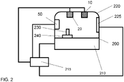
- Humidity sensors 10 and microbiological sensors 20 are distributed over the transport system. One possibility to fix these sensors is shown in Fig. 2 .
- the humidity sensors 10 and microbiological sensors 20 are fixed at a cover 220 over the transport plane 200. So these sensors are place in a tube like space bordered by the transport plane 200 and cover 220.
- microbiological sensors a real time bio aerosol sensors such as described in US20170209860 .
- Sensors to measure relative humidity are well known in the art and e.g. described in US5844138 .
- combinations of microbiological sensors with relative humidity sensors are known, so that the microbiological sensor 20 and the humidity sensor 10 can be realized in one device.
- control device 215 is shown only with its connection to the airflow generating devices 40.
- Other connections to the transport system, the sensors 10,20 and maybe also the pre-analytic systems 110, the analyzers 120, and the post-analytic devices 130 are omitted to keep an overview. These connections can be realized by an industry-bus standard cable based or with wireless communication. All the connections shown in Fig. 2 are also present for the embodiment shown in Fig. 1 for each respective device.
- FIG. 1 four airflow generating devices 40 are placed so that a laminar airflow can be generated.
- a negative pressure escape aperture 30 is installed in the cover 220. This allows generating a laminar airflow by one airflow generating device 40 in the region where the analyzers are connected to the transport plane 200. A laminar airflow will minimize the risk of cross contamination between tubes 230 transported by the carriers 240 on the transport plane 200. Usually open tubes 230 are transported in such a diagnostic laboratory distribution system 100.
- a additional airflow generating device 40 is need for the branch to the respective pre-analytic system 110. This additional airflow generating device 40 is connected to the control device 215 via a wireless communication.
- a uv-generating device 50 is shown. This is placed at the side of the cover 220. In a further embodiment the uv-generating devices 50 are placed always with a microbiological sensor 20.
- Fig. 2 shows a heating element 225 connected to the cover 220 to heat the cover 220.
- the heating element 225 can be realized as discrete heating element at distinct positions at the cover 220 or as a distributed heating element.
- a distribute heating element can be realized with heating wires included in the cover material over the whole length of the cover 220. The heating element 225 will heat up the cover so that condensation of any liquid can be prohibited at the cover 220. This avoid droplets which can contaminate the filling of the tubes 230 transported over the transport plane 200.
- Fig. 3 shows one embodiment of the method for a distribution system.
- step 310 the humidity of the air in the distribution system is controlled.
- the air is confined between a transport plane 200 and a cover 220 building some kind of tube.
- the signal of the humidity sensor 10 is sent to the control device 215.
- the control device 215 decides in step 332 whether the signal of the humidity sensor corresponding to the relative humidity in the air in the tube like air volume is above or below a predefined threshold.
- control device 215 If the value is above the pre-defined threshold the control device 215 will sent in step 334 to the airflow generating devices 40 a signal to start the airflow and if the signal is below the threshold the control device 215 sends in step 346 a stop signal to the airflow generating devices and the airflow will be stopped.
- the control device 215 further decides in step 330 if the signal of the humidity sensor 40 measured in step 310 is above a second predefined value. If the signal is above the second predefined value the control device 215 will start in step 340 the heating element 225 of the cover 220. If the signal is below the second pre-defined value the control device 215 will sent in step 342 a stop signal to the heating element 225.
- step 320 the microbiological sensor 20 measure the microbiological contamination of the air in the tube like air volume between the transport plane 200 and the cover 220.
- step 334 the control device 215 decides if the value of the microbiological sensor 20 is above or below a pre-defined microbiological threshold. If the value is above the pre-defined microbiological threshold the control device will send in step 344 a start signal to the airflow generating devices 40. If the value is below the pre-defined microbiological threshold, the control device 215 will send in step 346 a stop signal to airflow generating device 40.
- the airflow generating device 40 will give to a start signal a higher priority than to any stop signal. For instance if the airflow generating device gets at the same time a start signal of step 344 and a stop signal form step 346 due to different outcomes of the values of the humidity sensor 10 in step 310 and the microbiological sensor in step 320 the airflow generating device 40 will start to generate the airflow.
- step 336 the control device 215 decides if the value of the microbiological sensor 20 measured in step 320 is above or below a second pre-defined microbiological threshold. If the value is below the second pre-defined microbiological threshold the control device will sent in step 248 a stop signal to the uv-light generating devices 50. If the value is above the pre-defined second microbiological threshold the control device 215 sends in step 350 a signal to the drive means 210 to remove all goods 230 from the transport plane. If all goods are removed, the control device 215 sends in step 352 a start signal to the uv-light generating device 50. The control-device 215 gets feedback from the transport plane and the drive means so that the control device knows the position of all goods on the transport plane.
- the distribution system 100 is divided into separate portions so that in each portion the air in the tube like air volume is controlled independently for each portion by the control device 215.
- borders of the portions of the distribution system 100 are defined by the negative pressure escape apertures 30. This allows to separately use the above described methods to control the air contamination in each portion of the distribution system 100.
Landscapes
- Chemical & Material Sciences (AREA)
- Health & Medical Sciences (AREA)
- General Health & Medical Sciences (AREA)
- Life Sciences & Earth Sciences (AREA)
- Analytical Chemistry (AREA)
- Biochemistry (AREA)
- Physics & Mathematics (AREA)
- General Physics & Mathematics (AREA)
- Immunology (AREA)
- Pathology (AREA)
- Clinical Laboratory Science (AREA)
- Chemical Kinetics & Catalysis (AREA)
- Apparatus Associated With Microorganisms And Enzymes (AREA)
- Automatic Analysis And Handling Materials Therefor (AREA)
Abstract
Description
- Embodiments of the invention refer to a diagnostics laboratory distribution system.
- Diagnostics laboratory distribution system are described in e.g.
EP 3 095 739 A1 orWO2012/158541 . These publications describe laboratory sample distribution systems with passive carriers or self-propelling carriers on transport planes. - In the following a distribution system is any kind of probe transportation in a diagnostics laboratory within and in-between any analyzers, pre-analytic system, post analytic systems, storage devices etc..
- An object of the invention is to make a diagnostics laboratory distribution system more reliable and safer.
- This is realized by a device according to claim 1 and a method according to
claim 10. - A first aspect of the present invention concerns a diagnostics laboratory distribution system, wherein the distribution system comprises a number of carriers wherein the carriers are adapted to carry one or more goods. Goods can be anything to be distributed in a diagnostics laboratory, e.g. sample tubes, reagent containers, pipetting tips, other consumable material, quality control samples, waste in any form etc..
A transport plane of the distribution system is adapted to support the carriers. - Drive means of the distribution system are adapted to move the carriers on the transport plane. Drive means can be realized e.g. as magnetic coils underneath the transport plane in connection with a magnetic device in the carriers or as electrical motors in the carriers itself connected to wheels of the carriers.
A control device of the distribution system controls the drive means. The control device is e.g. realized as a central or distributed computing device connected to the drivers of the coils underneath the transport plane or as a distributed control device in the carrier to control the electrical motor of the carrier.
The distribution system comprises a cover for the transport plane. Furthermore the distribution system comprises humidity sensors connected to the control device and an airflow generating device connected to the control device. The humidity sensors measures the humidity of the air between the cover and the transport plane.
The airflow generating devices are distributed over the distribution system to generate an airflow between the cover and the transport plane,
wherein the control device is configured to start the airflow generating devices if the humidity sensors measure a humidity above a pre-defined threshold value.
Airflow generating devices can be one single device or multiple devices depending on the geometry of the transport plane layout. For instance a single straight forward pathway only need one airflow generating devices wherein a complex design with multiple crossings and branchings need more than one airflow generating device.
In a further embodiment, the pre-defined humidity threshold depends on the goods to be transported.
In another embodiment thresholds are used well below the dew-point in the range of 60%-90% relative humidity, in particular 70%-80% or 75% relative humidity. - Another aspect of the invention is a distribution system wherein the control device is configured to stop the airflow generating devices, if the humidity sensors measure a humidity value below the pre-defined threshold.
- A further aspect of the inventive distribution system is that the airflow generating devices generates a laminar airflow.
A laminar flow means that the air particles follow smooth paths in layers.
In a further embodiment the humidity sensor are distributed over the distribution system to control humidity above the transport plane. The distribution is such that in all areas the humidity of the air is measured. - In still another embodiment, the humidity sensors work continuously. In a further embodiment the humidity sensors are adapted to measure the humidity, if a carrier is in the sensor range of the respective humidity sensor.
- Another aspect of the invention is a distribution system wherein the transport plane of the distribution system is arranged in lanes and crossings, wherein the cover of the distribution system comprises negative pressure escape apertures, wherein the negative pressure escape apertures are placed surrounding or at the crossings, so that the laminar airflow is maintained at the crossings.
In a special embodiment, the negative pressure escape apertures are placed in pairs at opposite sides of the crossings. - A further aspect of the inventive distribution system is that the cover comprises heating elements to heat the cover; wherein the control device is connected to the heating elements, wherein the control device is configured to start and stop the heating elements depending on a predefined second threshold of the signals of the humidity sensors.
In a further embodiment the pre-defined second threshold of the signals of the humidity sensors are used below the dew-point in the range of 70%-99% relative humidity, in particular 80%-90% or 95% relative humidity. In another embodiment the pre-defined second threshold is higher than the pre-defined threshold measured in relative humidity. - Sensors to measure relative humidity are well known in the art and e.g. described in
US5844138 . - Another aspect of the invention is a distribution system, wherein the distribution system comprises microbiological sensors, which are arranged between the transport plane and the cover and are connected to the control device and wherein the control device is configured to start the airflow generating devices if the control device receives from the microbiological sensor a signal above a predefined biological threshold.
- A further aspect of the inventive distribution system is that the control device is configured to stop the airflow generating devices if the signals of the microbiological sensor are below the predefined biological threshold.
The threshold value depends on the sensor used. Examples of microbiological sensors a real time bio aerosol sensors such as described inUS20170209860 . - Another aspect of the invention is a distribution system, wherein the distribution system comprises an uv-light generating device.
- In other embodiments the uv-light generating devices can be realized as one or more off light bulbs, LEDs, lasers, LED-lasers and so on. UV-light as in particular a wavelength between 100 and 400 nm or 200 to 300 nm.
- A further aspect of the inventive distribution system is that the control devices is connected to the uv-light generating device and starts the uv-light generating device when the signal of the microbiological sensors is above a second pre-defined biological threshold and in particular stops the uv-light generating devices if the signal of the microbiological sensors is below the second biological threshold.
- In a further embodiment the second pre-defined biological threshold is higher than the predefined biological sensor meaning that with increasing contamination first the airflow generating devices are started and if the contamination still increases the uv-light generating devices are switched on.
In a further embodiment the microbiological sensor measures the opacity of a nutrient rich detection site and the signal is higher the more opaque the nutrient rich detection site is and/or the faster the opacity increases. - Another aspect of the invention is a method for a distribution system wherein the distribution system comprises a number of carriers wherein the carriers are adapted to carry one or more goods,
a transport plane wherein the transport plane is adapted to support the carriers,
drive means, wherein the drive means are adapted to move the carriers on the transport plane, and a control device to control the drive means,
wherein the distribution system comprises a cover for the transport plane,
wherein the distribution system comprises humidity sensors connected to the control device and an airflow generating devices connected to the control device,
wherein the airflow generating devices are distributed over the distribution system to generate an airflow between the cover and the transport plane, wherein the control device starts the airflow generating devices if the humidity sensors measure a humidity above a pre-defined threshold value. - In particular the method for a distribution system is a method to analyze the air in the distribution system and to keep the air safe in the distribution system. More in particular the method allows reducing cross contamination between substance transported by the distribution system.
- A further aspect of the inventive method for a distribution system is that the distribution system comprise microbiological sensors, wherein the control device starts the airflow generating devices if the microbiological sensor connected to the control device sends a signal above a microbiological threshold and stops the airflow generating devices if the signal is below the microbiological threshold.
- Another aspect of the invention is a method for a distribution system, wherein the distribution system comprise uv-light generating devices connected to the control device, wherein the control device starts the uv-light generating devices if the microbiological sensor connected to the control device sends a signal above a second microbiological threshold and stops the uv-light generating devices if the signal is below the second microbiological threshold.
- A further aspect of the inventive method for a distribution system is that the control device activates the drive means so that all carriers are moved out of an area of the transport plane for which the signal of the microbiological sensor is above the second microbiological threshold before the uv-light generating devices are switched on.
- Another aspect of the invention is a method for a distribution system, wherein a start signal has always higher priority than any stop signal of the airflow generating devices.
- However, other embodiments are feasible which relates to a combination of features disclosed herewith.
-
-
Figure 1 shows a schematic overview of a diagnostics laboratory with a diagnostics laboratory distribution system. -
Figure 2 shows a schematic cross section of a transport device of a diagnostic distribution system. - Further optional features and embodiments of the invention will be disclosed in more detail in the subsequent description of preferred embodiments, preferably in conjunction with the dependent claims. Therein, the respective optional features may be realized in an isolated fashion as well as in any arbitrary feasible combination, as the skilled person will realize. The scope of the invention is not restricted by the preferred embodiments. The embodiments are schematically depicted in the Figures. Therein, identical reference numbers in these Figures refer to identical or functionally comparable elements.
-
Figures 1 shows a schematic of a top view of a diagnosticlaboratory distribution system 100.
Pre-analytic systems 110 are able to receive goods by an operator. In diagnostics labs these are usually tubes filled with a body fluid of a patient. These tubes are sorted, centrifuged and the quality of the body fluid is checked. The pre-analytic systems hand-over thegoods 230 into thecarriers 240.
Thecarriers 240 transports the goods/tubes 230 on thetransport plane 200 toanalyzers 120. In theanalyzers 120 some part of the body fluid is sucked out of the tubes to be analyzed. After the required measurements are done thetubes 230 are transported by thecarriers 240 on thetransport plane 200 to thepost-analytic stations 130.
Thesepost-analytic stations 130 have a sorting device to put thetubes 230 into carriers which are then transported into a fridge. If a further measurement is required for a special tube thepost-analytic station 130 can retrieve the tube and put it again into acarrier 240, so that the tube can be transported again to ananalyzer 120 which makes the required measurement. - A transport system with
transport plane 200 connects thepre-analytic systems 110, theanalyzers 120 and thepost-analytic stations 130, so that thecarriers 240 can be transported moving on thetransport plane 200. -
Humidity sensors 10 andmicrobiological sensors 20 are distributed over the transport system. One possibility to fix these sensors is shown inFig. 2 . Thehumidity sensors 10 andmicrobiological sensors 20 are fixed at acover 220 over thetransport plane 200. So these sensors are place in a tube like space bordered by thetransport plane 200 andcover 220. - Examples of microbiological sensors a real time bio aerosol sensors such as described in
US20170209860 . Sensors to measure relative humidity are well known in the art and e.g. described inUS5844138 . Also combinations of microbiological sensors with relative humidity sensors are known, so that themicrobiological sensor 20 and thehumidity sensor 10 can be realized in one device. - In
Fig. 1 thecontrol device 215 is shown only with its connection to theairflow generating devices 40. Other connections to the transport system, thesensors pre-analytic systems 110, theanalyzers 120, and thepost-analytic devices 130 are omitted to keep an overview. These connections can be realized by an industry-bus standard cable based or with wireless communication. All the connections shown inFig. 2 are also present for the embodiment shown inFig. 1 for each respective device. - As can be seen in
Fig. 1 fourairflow generating devices 40 are placed so that a laminar airflow can be generated. For small branches of the transport system connected to thepre-analytic systems 110 or postanalytic devices 130 no specialairflow generating devices 40 are installed. - At the main junctions of the
transport plane 200, a negativepressure escape aperture 30 is installed in thecover 220. This allows generating a laminar airflow by oneairflow generating device 40 in the region where the analyzers are connected to thetransport plane 200.
A laminar airflow will minimize the risk of cross contamination betweentubes 230 transported by thecarriers 240 on thetransport plane 200. Usuallyopen tubes 230 are transported in such a diagnosticlaboratory distribution system 100. - At the left junction in
Fig.1 two negative pressure escape apertures are placed opposite each other to keep the airflow laminar. A additionalairflow generating device 40 is need for the branch to the respectivepre-analytic system 110. This additionalairflow generating device 40 is connected to thecontrol device 215 via a wireless communication. - In
Fig. 2 additionally a uv-generatingdevice 50 is shown. This is placed at the side of thecover 220. In a further embodiment the uv-generatingdevices 50 are placed always with amicrobiological sensor 20. - In addition,
Fig. 2 shows aheating element 225 connected to thecover 220 to heat thecover 220. Theheating element 225 can be realized as discrete heating element at distinct positions at thecover 220 or as a distributed heating element.
In a not shown embodiment a distribute heating element can be realized with heating wires included in the cover material over the whole length of thecover 220.
Theheating element 225 will heat up the cover so that condensation of any liquid can be prohibited at thecover 220. This avoid droplets which can contaminate the filling of thetubes 230 transported over thetransport plane 200. -
Fig. 3 shows one embodiment of the method for a distribution system. Instep 310 the humidity of the air in the distribution system is controlled.
In a special embodiment, the air is confined between atransport plane 200 and acover 220 building some kind of tube.
The signal of thehumidity sensor 10 is sent to thecontrol device 215. Thecontrol device 215 decides instep 332 whether the signal of the humidity sensor corresponding to the relative humidity in the air in the tube like air volume is above or below a predefined threshold. If the value is above the pre-defined threshold thecontrol device 215 will sent instep 334 to the airflow generating devices 40 a signal to start the airflow and if the signal is below the threshold thecontrol device 215 sends in step 346 a stop signal to the airflow generating devices and the airflow will be stopped. - The
control device 215 further decides instep 330 if the signal of thehumidity sensor 40 measured instep 310 is above a second predefined value. If the signal is above the second predefined value thecontrol device 215 will start instep 340 theheating element 225 of thecover 220. If the signal is below the second pre-defined value thecontrol device 215 will sent in step 342 a stop signal to theheating element 225. - In
step 320 themicrobiological sensor 20 measure the microbiological contamination of the air in the tube like air volume between thetransport plane 200 and thecover 220. Instep 334, thecontrol device 215 decides if the value of themicrobiological sensor 20 is above or below a pre-defined microbiological threshold. If the value is above the pre-defined microbiological threshold the control device will send in step 344 a start signal to theairflow generating devices 40. If the value is below the pre-defined microbiological threshold, thecontrol device 215 will send in step 346 a stop signal to airflow generatingdevice 40. - The
airflow generating device 40 will give to a start signal a higher priority than to any stop signal. For instance if the airflow generating device gets at the same time a start signal ofstep 344 and a stopsignal form step 346 due to different outcomes of the values of thehumidity sensor 10 instep 310 and the microbiological sensor instep 320 theairflow generating device 40 will start to generate the airflow. - In
step 336 thecontrol device 215 decides if the value of themicrobiological sensor 20 measured instep 320 is above or below a second pre-defined microbiological threshold.
If the value is below the second pre-defined microbiological threshold the control device will sent in step 248 a stop signal to the uv-light generating devices 50. If the value is above the pre-defined second microbiological threshold thecontrol device 215 sends in step 350 a signal to the drive means 210 to remove allgoods 230 from the transport plane. If all goods are removed, thecontrol device 215 sends in step 352 a start signal to the uv-light generating device 50. The control-device 215 gets feedback from the transport plane and the drive means so that the control device knows the position of all goods on the transport plane. - In a further embodiment the
distribution system 100 is divided into separate portions so that in each portion the air in the tube like air volume is controlled independently for each portion by thecontrol device 215. In particular, borders of the portions of thedistribution system 100 are defined by the negativepressure escape apertures 30.
This allows to separately use the above described methods to control the air contamination in each portion of thedistribution system 100.
Claims (14)
- A diagnostic laboratory distribution system (100), wherein the distribution system (100) comprises a number of carriers (240) wherein the carriers (240) are adapted to carry one or more goods (230),
a transport plane (200) wherein the transport plane (200) is adapted to support the carriers(240),
drive means (210), wherein the drive means (210) are adapted to move the carriers (240) on the transport plane (200), and a control device (215) to control the drive means (210),
wherein the distribution system (100) comprises a cover (220) for the transport plane (200),
wherein the distribution system (100) comprises humidity sensors (10) to measure humidity above the transport plane (200) connected to the control device (215) and airflow generating devices (40) connected to the control device (215),
wherein the airflow generating devices (40) are distributed over the distribution system (100) to generate an airflow between the cover (220) and the transport plane (200),
wherein the control device (215) is configured to start the airflow generating devices (40) if the humidity sensors (10) measure a humidity above a pre-defined threshold value. - A distribution system according to any of the previous claims wherein the control device (215) is configured to stop the airflow generating devices (40), if the humidity sensors (10) measure a humidity value below the pre-defined threshold.
- A distribution system according to any of the previous claims, wherein the airflow generating devices (40) generates a laminar airflow.
- A distribution system according to any of the previous claims, wherein the transport plane (200) of the distribution system is arranged in lanes and crossings, wherein the cover (220) of the distribution system comprises negative pressure escape apertures (30), wherein the negative pressure escape apertures (30) are placed at the crossings.
- A distribution system (200) according to any of the previous claims, wherein the cover (220) comprises heating elements (225) to heat the cover (220); wherein the control device (215) is connected to the heating elements (225), wherein the control device (215) is configured to start and stop the heating elements (225) depending on a predefined second threshold of the signals of the humidity sensors (10).
- A distribution system (100) according to any of the previous claims, wherein the distribution system (100) comprises microbiological sensors (20), which are arranged between the transport plane (200) and the cover (220) and are connected to the control device (215) and wherein the control device (215) is configured to start the airflow generating devices (40) if the control device receives from the microbiological sensor (40) a signal above a predefined biological threshold.
- A distribution system (100) according to the previous claim, wherein the control device (215) is configured to stop the airflow generating devices (40) if the signals of the microbiological sensor (20) are below the predefined biological threshold.
- A distribution system (100) according to the two previous claims, wherein the distribution system comprises an uv-light generating device (50).
- A distribution system (100) according to the three previous claims, wherein the control devices (215) is connected to the uv-light generating device (50) and starts the uv-light generating device (50) when the signal of the microbiological sensors (20) is above a second biological threshold and in particular stops the uv-light generating devices if the signal of the microbiological sensors is below the second biological threshold.
- A method for a diagnostic laboratory distribution system (100) wherein the distribution system (100) comprises a number of carriers (240) wherein the carriers (240) are adapted to carry one or more goods (230),
a transport plane (200) wherein the transport plane (200) is adapted to support the carriers (240),
drive means (210), wherein the drive means (210) are adapted to move the carriers (240) on the transport plane (200), and a control device (215) to control the drive means (210),
wherein the distribution system (100) comprises a cover (220) for the transport plane,
wherein the distribution system (100) comprises humidity sensors (10) connected to the control device (215) and airflow generating devices (40) connected to the control device (215),
wherein the airflow generating devices (40) are distributed over the distribution system (100) to generate an airflow between the cover (220) and the transport plane (200), wherein the control device (215) starts the airflow generating devices (40) if the humidity sensors (10) measure a humidity above a pre-defined threshold value. - A method for a distribution system (100) according to the previous claim, wherein the distribution system (100) comprise microbiological sensors (20), wherein the control device (215) starts the airflow generating devices (40) if the microbiological sensor (20) connected to the control device (215) sends a signal above a predefined microbiological threshold and stops the airflow generating devices (40) if the signal is below the pre-defined microbiological threshold.
- A method for a distribution system (100) according to the previous claim, wherein the distribution system comprise uv-light generating devices (50) connected to the control device (215), wherein the control device (215) starts the uv-light generating devices (50) if the microbiological sensor connected to the control device (215) sends a signal above a second pre-defined microbiological threshold and stops the uv-light generating devices (50) if the signal is below the second pre-defined microbiological threshold.
- A method for a distribution system (100) according to the previous claim, wherein the control device (215) activates the drive means (210) so that all carriers (240) are moved out of an area of the transport plane (200) for which the signal of the microbiological sensor (20) is above the second pre-defined microbiological threshold before the uv-light generating devices (50) are switched on.
- A method for a distribution system (100) according to any of the three previous claims, wherein a start signal has always higher priority than any stop signal of the airflow generating devices (40).
Priority Applications (4)
| Application Number | Priority Date | Filing Date | Title |
|---|---|---|---|
| EP20383055.9A EP4008433B1 (en) | 2020-12-03 | 2020-12-03 | Diagnostics laboratory distribution system |
| US17/452,781 US12345727B2 (en) | 2020-12-03 | 2021-10-29 | Diagnostic laboratory distribution system |
| JP2021196513A JP7350043B2 (en) | 2020-12-03 | 2021-12-02 | Diagnostic laboratory delivery system |
| CN202111460553.1A CN114594275B (en) | 2020-12-03 | 2021-12-02 | Diagnostic laboratory allocation system |
Applications Claiming Priority (1)
| Application Number | Priority Date | Filing Date | Title |
|---|---|---|---|
| EP20383055.9A EP4008433B1 (en) | 2020-12-03 | 2020-12-03 | Diagnostics laboratory distribution system |
Publications (2)
| Publication Number | Publication Date |
|---|---|
| EP4008433A1 true EP4008433A1 (en) | 2022-06-08 |
| EP4008433B1 EP4008433B1 (en) | 2024-01-24 |
Family
ID=73834413
Family Applications (1)
| Application Number | Title | Priority Date | Filing Date |
|---|---|---|---|
| EP20383055.9A Active EP4008433B1 (en) | 2020-12-03 | 2020-12-03 | Diagnostics laboratory distribution system |
Country Status (4)
| Country | Link |
|---|---|
| US (1) | US12345727B2 (en) |
| EP (1) | EP4008433B1 (en) |
| JP (1) | JP7350043B2 (en) |
| CN (1) | CN114594275B (en) |
Citations (7)
| Publication number | Priority date | Publication date | Assignee | Title |
|---|---|---|---|---|
| US5844138A (en) | 1997-03-07 | 1998-12-01 | Veris Industries, Inc. | Humidity sensor |
| WO2012158541A1 (en) | 2011-05-13 | 2012-11-22 | Beckman Coulter, Inc. | System and method including laboratory product transport element |
| EP3095739A1 (en) | 2015-05-22 | 2016-11-23 | Roche Diagniostics GmbH | Method of operating a laboratory sample distribution system, laboratory sample distribution system and laboratory automation system |
| US20170209860A1 (en) | 2016-01-21 | 2017-07-27 | Nuwave Sensor Technology Limited | Method and apparatus for remote identification and monitoring of airborne microbial activity |
| US20180202908A1 (en) * | 2015-07-20 | 2018-07-19 | Brooks Automation, Inc. | Automated Vault Module |
| US20200191808A1 (en) * | 2014-07-28 | 2020-06-18 | Douglas Scientific, LLC | Instrument for analyzing biological samples and reagents |
| CN211323029U (en) * | 2019-11-11 | 2020-08-25 | 云南中烟工业有限责任公司 | Shaping drying system of special thick liquid method reconstituted tobacco of cigarette is not burnt in heating |
Family Cites Families (17)
| Publication number | Priority date | Publication date | Assignee | Title |
|---|---|---|---|---|
| US3582144A (en) * | 1969-07-14 | 1971-06-01 | Air Preheater | Valve for air conveyor |
| JPH01148966A (en) | 1987-12-04 | 1989-06-12 | Hitachi Kiden Kogyo Ltd | Sample transport device |
| JPH02157017A (en) | 1988-12-07 | 1990-06-15 | Fuji Photo Film Co Ltd | Dry air production apparatus and its usage |
| US5526705A (en) * | 1994-08-05 | 1996-06-18 | Tyler Limited Partnership | Automated work station for analyzing soil samples |
| EP1248113B1 (en) | 2000-01-12 | 2011-06-29 | Hitachi, Ltd. | Automatic analyzer and rack transfer device |
| US20090090022A1 (en) * | 2007-10-09 | 2009-04-09 | Hememics Biotechnologies, Inc. | Desiccation Chamber and Methods for Drying Biological Materials |
| WO2009130360A1 (en) * | 2008-04-22 | 2009-10-29 | Tuula Suontamo | Information technology arrangement based on embedded technology for measuring, analyzing and foreseeing the cleanness of surface materials and indoor air |
| DE102010028769A1 (en) * | 2010-05-07 | 2011-11-10 | Pvt Probenverteiltechnik Gmbh | System for transporting containers between different stations and container carriers |
| EP2589968A1 (en) * | 2011-11-04 | 2013-05-08 | Roche Diagnostics GmbH | Laboratory sample distribution system, laboratory system and method of operating |
| EP2589966A1 (en) * | 2011-11-04 | 2013-05-08 | Roche Diagnostics GmbH | Laboratory sample distribution system and corresponding method of operation |
| JP2016176902A (en) | 2015-03-23 | 2016-10-06 | セイコーエプソン株式会社 | Electronic component conveyance device and electronic component inspection device |
| EP3139175B1 (en) * | 2015-09-01 | 2021-12-15 | Roche Diagnostics GmbH | Laboratory cargo distribution system, laboratory automation system and method of operating a laboratory cargo distribution system |
| EP3355064A1 (en) * | 2017-01-25 | 2018-08-01 | Roche Diagnostics GmbH | Laboratory sample distribution system and laboratory automation system |
| EP3379218B1 (en) * | 2017-03-21 | 2020-07-15 | MEAS France | Method for providing a diagnostic on a combined humidity and temperature sensor |
| CN207741277U (en) * | 2018-01-18 | 2018-08-17 | 广州毅宁净化工程有限公司 | A kind of Medical purification remote monitoring apparatus for air-conditioning system |
| US11567092B2 (en) * | 2018-12-31 | 2023-01-31 | Robert Bosch Gmbh | System and method for operating a mold detecting device |
| US11184739B1 (en) * | 2020-06-19 | 2021-11-23 | Honeywel International Inc. | Using smart occupancy detection and control in buildings to reduce disease transmission |
-
2020
- 2020-12-03 EP EP20383055.9A patent/EP4008433B1/en active Active
-
2021
- 2021-10-29 US US17/452,781 patent/US12345727B2/en active Active
- 2021-12-02 CN CN202111460553.1A patent/CN114594275B/en active Active
- 2021-12-02 JP JP2021196513A patent/JP7350043B2/en active Active
Patent Citations (7)
| Publication number | Priority date | Publication date | Assignee | Title |
|---|---|---|---|---|
| US5844138A (en) | 1997-03-07 | 1998-12-01 | Veris Industries, Inc. | Humidity sensor |
| WO2012158541A1 (en) | 2011-05-13 | 2012-11-22 | Beckman Coulter, Inc. | System and method including laboratory product transport element |
| US20200191808A1 (en) * | 2014-07-28 | 2020-06-18 | Douglas Scientific, LLC | Instrument for analyzing biological samples and reagents |
| EP3095739A1 (en) | 2015-05-22 | 2016-11-23 | Roche Diagniostics GmbH | Method of operating a laboratory sample distribution system, laboratory sample distribution system and laboratory automation system |
| US20180202908A1 (en) * | 2015-07-20 | 2018-07-19 | Brooks Automation, Inc. | Automated Vault Module |
| US20170209860A1 (en) | 2016-01-21 | 2017-07-27 | Nuwave Sensor Technology Limited | Method and apparatus for remote identification and monitoring of airborne microbial activity |
| CN211323029U (en) * | 2019-11-11 | 2020-08-25 | 云南中烟工业有限责任公司 | Shaping drying system of special thick liquid method reconstituted tobacco of cigarette is not burnt in heating |
Also Published As
| Publication number | Publication date |
|---|---|
| US20220178957A1 (en) | 2022-06-09 |
| US12345727B2 (en) | 2025-07-01 |
| JP2022089188A (en) | 2022-06-15 |
| JP7350043B2 (en) | 2023-09-25 |
| EP4008433B1 (en) | 2024-01-24 |
| CN114594275A (en) | 2022-06-07 |
| CN114594275B (en) | 2026-05-08 |
Similar Documents
| Publication | Publication Date | Title |
|---|---|---|
| EP3355065B1 (en) | Laboratory sample distribution system and laboratory automation system | |
| JP5993388B2 (en) | Method and apparatus for detecting clots in liquid and laboratory automation system | |
| JP2731626B2 (en) | How to calibrate an automated analyzer | |
| US20220011335A1 (en) | Automated diagnostic analyzers having rear accessible track systems and related methods | |
| US10012666B2 (en) | Sample distribution system and laboratory automation system | |
| US6647397B2 (en) | Distributed database for analytical instruments | |
| JP2018128449A (en) | Laboratory | |
| US20060097155A1 (en) | Substrate for transporting liquid, a system for analysis and a method for analysis | |
| CN108344877A (en) | Laboratory sample dispensing system and laboratory automation system | |
| KR20140092377A (en) | Aliquotter system and workflow | |
| EP2770317A1 (en) | Apparatus for determining a vertical position of at least one interface between a first component and at least one second component and laboratory automation system | |
| EP3487630B1 (en) | Temperature controlled transport puck | |
| JPH05506512A (en) | Automatic analyzer with temperature controlled chamber | |
| US20150355207A1 (en) | Test menu expansion system and method | |
| JP2015510590A (en) | Intelligent intelligent multi-functional carrier and integrated automation system for material distribution and transport | |
| JPH11264828A (en) | Sample transport system | |
| CN103364573B (en) | Sample processing system | |
| EP4008433B1 (en) | Diagnostics laboratory distribution system | |
| JPH02266259A (en) | Electrophoretic apparatus | |
| EP3833466B1 (en) | Method and device for determining the concentration of analytes in whole blood | |
| JP6234765B2 (en) | Sample analysis automatic analysis system | |
| CN112585437B (en) | Liquid level detecting device | |
| EP4234677A1 (en) | Analysis apparatus | |
| HK1197453A (en) | Method and apparatus for detecting clots in a liquid and laboratory automation system | |
| CN120604102A (en) | Liquid level detection device and liquid level detection method |
Legal Events
| Date | Code | Title | Description |
|---|---|---|---|
| PUAI | Public reference made under article 153(3) epc to a published international application that has entered the european phase |
Free format text: ORIGINAL CODE: 0009012 |
|
| STAA | Information on the status of an ep patent application or granted ep patent |
Free format text: STATUS: THE APPLICATION HAS BEEN PUBLISHED |
|
| AK | Designated contracting states |
Kind code of ref document: A1 Designated state(s): AL AT BE BG CH CY CZ DE DK EE ES FI FR GB GR HR HU IE IS IT LI LT LU LV MC MK MT NL NO PL PT RO RS SE SI SK SM TR |
|
| STAA | Information on the status of an ep patent application or granted ep patent |
Free format text: STATUS: REQUEST FOR EXAMINATION WAS MADE |
|
| 17P | Request for examination filed |
Effective date: 20221208 |
|
| RBV | Designated contracting states (corrected) |
Designated state(s): AL AT BE BG CH CY CZ DE DK EE ES FI FR GB GR HR HU IE IS IT LI LT LU LV MC MK MT NL NO PL PT RO RS SE SI SK SM TR |
|
| RIC1 | Information provided on ipc code assigned before grant |
Ipc: G01N 35/00 20060101ALI20230413BHEP Ipc: G01N 35/04 20060101ALI20230413BHEP Ipc: B01L 1/02 20060101AFI20230413BHEP |
|
| GRAP | Despatch of communication of intention to grant a patent |
Free format text: ORIGINAL CODE: EPIDOSNIGR1 |
|
| STAA | Information on the status of an ep patent application or granted ep patent |
Free format text: STATUS: GRANT OF PATENT IS INTENDED |
|
| GRAJ | Information related to disapproval of communication of intention to grant by the applicant or resumption of examination proceedings by the epo deleted |
Free format text: ORIGINAL CODE: EPIDOSDIGR1 |
|
| GRAP | Despatch of communication of intention to grant a patent |
Free format text: ORIGINAL CODE: EPIDOSNIGR1 |
|
| INTG | Intention to grant announced |
Effective date: 20230606 |
|
| INTG | Intention to grant announced |
Effective date: 20230627 |
|
| INTG | Intention to grant announced |
Effective date: 20230704 |
|
| GRAS | Grant fee paid |
Free format text: ORIGINAL CODE: EPIDOSNIGR3 |
|
| GRAA | (expected) grant |
Free format text: ORIGINAL CODE: 0009210 |
|
| STAA | Information on the status of an ep patent application or granted ep patent |
Free format text: STATUS: THE PATENT HAS BEEN GRANTED |
|
| AK | Designated contracting states |
Kind code of ref document: B1 Designated state(s): AL AT BE BG CH CY CZ DE DK EE ES FI FR GB GR HR HU IE IS IT LI LT LU LV MC MK MT NL NO PL PT RO RS SE SI SK SM TR |
|
| REG | Reference to a national code |
Ref country code: GB Ref legal event code: FG4D |
|
| REG | Reference to a national code |
Ref country code: CH Ref legal event code: EP |
|
| REG | Reference to a national code |
Ref country code: DE Ref legal event code: R096 Ref document number: 602020024805 Country of ref document: DE |
|
| REG | Reference to a national code |
Ref country code: IE Ref legal event code: FG4D |
|
| REG | Reference to a national code |
Ref country code: LT Ref legal event code: MG9D |
|
| REG | Reference to a national code |
Ref country code: NL Ref legal event code: MP Effective date: 20240124 |
|
| PG25 | Lapsed in a contracting state [announced via postgrant information from national office to epo] |
Ref country code: NL Free format text: LAPSE BECAUSE OF FAILURE TO SUBMIT A TRANSLATION OF THE DESCRIPTION OR TO PAY THE FEE WITHIN THE PRESCRIBED TIME-LIMIT Effective date: 20240124 |
|
| PG25 | Lapsed in a contracting state [announced via postgrant information from national office to epo] |
Ref country code: NL Free format text: LAPSE BECAUSE OF FAILURE TO SUBMIT A TRANSLATION OF THE DESCRIPTION OR TO PAY THE FEE WITHIN THE PRESCRIBED TIME-LIMIT Effective date: 20240124 |
|
| PG25 | Lapsed in a contracting state [announced via postgrant information from national office to epo] |
Ref country code: IS Free format text: LAPSE BECAUSE OF FAILURE TO SUBMIT A TRANSLATION OF THE DESCRIPTION OR TO PAY THE FEE WITHIN THE PRESCRIBED TIME-LIMIT Effective date: 20240524 |
|
| PG25 | Lapsed in a contracting state [announced via postgrant information from national office to epo] |
Ref country code: LT Free format text: LAPSE BECAUSE OF FAILURE TO SUBMIT A TRANSLATION OF THE DESCRIPTION OR TO PAY THE FEE WITHIN THE PRESCRIBED TIME-LIMIT Effective date: 20240124 |
|
| PG25 | Lapsed in a contracting state [announced via postgrant information from national office to epo] |
Ref country code: GR Free format text: LAPSE BECAUSE OF FAILURE TO SUBMIT A TRANSLATION OF THE DESCRIPTION OR TO PAY THE FEE WITHIN THE PRESCRIBED TIME-LIMIT Effective date: 20240425 |
|
| REG | Reference to a national code |
Ref country code: AT Ref legal event code: MK05 Ref document number: 1651757 Country of ref document: AT Kind code of ref document: T Effective date: 20240124 |
|
| PG25 | Lapsed in a contracting state [announced via postgrant information from national office to epo] |
Ref country code: HR Free format text: LAPSE BECAUSE OF FAILURE TO SUBMIT A TRANSLATION OF THE DESCRIPTION OR TO PAY THE FEE WITHIN THE PRESCRIBED TIME-LIMIT Effective date: 20240124 Ref country code: RS Free format text: LAPSE BECAUSE OF FAILURE TO SUBMIT A TRANSLATION OF THE DESCRIPTION OR TO PAY THE FEE WITHIN THE PRESCRIBED TIME-LIMIT Effective date: 20240424 |
|
| PG25 | Lapsed in a contracting state [announced via postgrant information from national office to epo] |
Ref country code: ES Free format text: LAPSE BECAUSE OF FAILURE TO SUBMIT A TRANSLATION OF THE DESCRIPTION OR TO PAY THE FEE WITHIN THE PRESCRIBED TIME-LIMIT Effective date: 20240124 |
|
| PG25 | Lapsed in a contracting state [announced via postgrant information from national office to epo] |
Ref country code: AT Free format text: LAPSE BECAUSE OF FAILURE TO SUBMIT A TRANSLATION OF THE DESCRIPTION OR TO PAY THE FEE WITHIN THE PRESCRIBED TIME-LIMIT Effective date: 20240124 |
|
| PG25 | Lapsed in a contracting state [announced via postgrant information from national office to epo] |
Ref country code: RS Free format text: LAPSE BECAUSE OF FAILURE TO SUBMIT A TRANSLATION OF THE DESCRIPTION OR TO PAY THE FEE WITHIN THE PRESCRIBED TIME-LIMIT Effective date: 20240424 Ref country code: NO Free format text: LAPSE BECAUSE OF FAILURE TO SUBMIT A TRANSLATION OF THE DESCRIPTION OR TO PAY THE FEE WITHIN THE PRESCRIBED TIME-LIMIT Effective date: 20240424 Ref country code: LT Free format text: LAPSE BECAUSE OF FAILURE TO SUBMIT A TRANSLATION OF THE DESCRIPTION OR TO PAY THE FEE WITHIN THE PRESCRIBED TIME-LIMIT Effective date: 20240124 Ref country code: IS Free format text: LAPSE BECAUSE OF FAILURE TO SUBMIT A TRANSLATION OF THE DESCRIPTION OR TO PAY THE FEE WITHIN THE PRESCRIBED TIME-LIMIT Effective date: 20240524 Ref country code: HR Free format text: LAPSE BECAUSE OF FAILURE TO SUBMIT A TRANSLATION OF THE DESCRIPTION OR TO PAY THE FEE WITHIN THE PRESCRIBED TIME-LIMIT Effective date: 20240124 Ref country code: GR Free format text: LAPSE BECAUSE OF FAILURE TO SUBMIT A TRANSLATION OF THE DESCRIPTION OR TO PAY THE FEE WITHIN THE PRESCRIBED TIME-LIMIT Effective date: 20240425 Ref country code: FI Free format text: LAPSE BECAUSE OF FAILURE TO SUBMIT A TRANSLATION OF THE DESCRIPTION OR TO PAY THE FEE WITHIN THE PRESCRIBED TIME-LIMIT Effective date: 20240124 Ref country code: ES Free format text: LAPSE BECAUSE OF FAILURE TO SUBMIT A TRANSLATION OF THE DESCRIPTION OR TO PAY THE FEE WITHIN THE PRESCRIBED TIME-LIMIT Effective date: 20240124 Ref country code: BG Free format text: LAPSE BECAUSE OF FAILURE TO SUBMIT A TRANSLATION OF THE DESCRIPTION OR TO PAY THE FEE WITHIN THE PRESCRIBED TIME-LIMIT Effective date: 20240124 Ref country code: AT Free format text: LAPSE BECAUSE OF FAILURE TO SUBMIT A TRANSLATION OF THE DESCRIPTION OR TO PAY THE FEE WITHIN THE PRESCRIBED TIME-LIMIT Effective date: 20240124 |
|
| PG25 | Lapsed in a contracting state [announced via postgrant information from national office to epo] |
Ref country code: PL Free format text: LAPSE BECAUSE OF FAILURE TO SUBMIT A TRANSLATION OF THE DESCRIPTION OR TO PAY THE FEE WITHIN THE PRESCRIBED TIME-LIMIT Effective date: 20240124 Ref country code: PT Free format text: LAPSE BECAUSE OF FAILURE TO SUBMIT A TRANSLATION OF THE DESCRIPTION OR TO PAY THE FEE WITHIN THE PRESCRIBED TIME-LIMIT Effective date: 20240524 |
|
| PG25 | Lapsed in a contracting state [announced via postgrant information from national office to epo] |
Ref country code: SE Free format text: LAPSE BECAUSE OF FAILURE TO SUBMIT A TRANSLATION OF THE DESCRIPTION OR TO PAY THE FEE WITHIN THE PRESCRIBED TIME-LIMIT Effective date: 20240124 Ref country code: PT Free format text: LAPSE BECAUSE OF FAILURE TO SUBMIT A TRANSLATION OF THE DESCRIPTION OR TO PAY THE FEE WITHIN THE PRESCRIBED TIME-LIMIT Effective date: 20240524 Ref country code: PL Free format text: LAPSE BECAUSE OF FAILURE TO SUBMIT A TRANSLATION OF THE DESCRIPTION OR TO PAY THE FEE WITHIN THE PRESCRIBED TIME-LIMIT Effective date: 20240124 Ref country code: LV Free format text: LAPSE BECAUSE OF FAILURE TO SUBMIT A TRANSLATION OF THE DESCRIPTION OR TO PAY THE FEE WITHIN THE PRESCRIBED TIME-LIMIT Effective date: 20240124 |
|
| PG25 | Lapsed in a contracting state [announced via postgrant information from national office to epo] |
Ref country code: DK Free format text: LAPSE BECAUSE OF FAILURE TO SUBMIT A TRANSLATION OF THE DESCRIPTION OR TO PAY THE FEE WITHIN THE PRESCRIBED TIME-LIMIT Effective date: 20240124 |
|
| PG25 | Lapsed in a contracting state [announced via postgrant information from national office to epo] |
Ref country code: SM Free format text: LAPSE BECAUSE OF FAILURE TO SUBMIT A TRANSLATION OF THE DESCRIPTION OR TO PAY THE FEE WITHIN THE PRESCRIBED TIME-LIMIT Effective date: 20240124 |
|
| PG25 | Lapsed in a contracting state [announced via postgrant information from national office to epo] |
Ref country code: CZ Free format text: LAPSE BECAUSE OF FAILURE TO SUBMIT A TRANSLATION OF THE DESCRIPTION OR TO PAY THE FEE WITHIN THE PRESCRIBED TIME-LIMIT Effective date: 20240124 Ref country code: EE Free format text: LAPSE BECAUSE OF FAILURE TO SUBMIT A TRANSLATION OF THE DESCRIPTION OR TO PAY THE FEE WITHIN THE PRESCRIBED TIME-LIMIT Effective date: 20240124 |
|
| REG | Reference to a national code |
Ref country code: DE Ref legal event code: R097 Ref document number: 602020024805 Country of ref document: DE |
|
| PG25 | Lapsed in a contracting state [announced via postgrant information from national office to epo] |
Ref country code: SK Free format text: LAPSE BECAUSE OF FAILURE TO SUBMIT A TRANSLATION OF THE DESCRIPTION OR TO PAY THE FEE WITHIN THE PRESCRIBED TIME-LIMIT Effective date: 20240124 |
|
| PG25 | Lapsed in a contracting state [announced via postgrant information from national office to epo] |
Ref country code: SM Free format text: LAPSE BECAUSE OF FAILURE TO SUBMIT A TRANSLATION OF THE DESCRIPTION OR TO PAY THE FEE WITHIN THE PRESCRIBED TIME-LIMIT Effective date: 20240124 Ref country code: SK Free format text: LAPSE BECAUSE OF FAILURE TO SUBMIT A TRANSLATION OF THE DESCRIPTION OR TO PAY THE FEE WITHIN THE PRESCRIBED TIME-LIMIT Effective date: 20240124 Ref country code: EE Free format text: LAPSE BECAUSE OF FAILURE TO SUBMIT A TRANSLATION OF THE DESCRIPTION OR TO PAY THE FEE WITHIN THE PRESCRIBED TIME-LIMIT Effective date: 20240124 Ref country code: DK Free format text: LAPSE BECAUSE OF FAILURE TO SUBMIT A TRANSLATION OF THE DESCRIPTION OR TO PAY THE FEE WITHIN THE PRESCRIBED TIME-LIMIT Effective date: 20240124 Ref country code: CZ Free format text: LAPSE BECAUSE OF FAILURE TO SUBMIT A TRANSLATION OF THE DESCRIPTION OR TO PAY THE FEE WITHIN THE PRESCRIBED TIME-LIMIT Effective date: 20240124 |
|
| PLBE | No opposition filed within time limit |
Free format text: ORIGINAL CODE: 0009261 |
|
| STAA | Information on the status of an ep patent application or granted ep patent |
Free format text: STATUS: NO OPPOSITION FILED WITHIN TIME LIMIT |
|
| PG25 | Lapsed in a contracting state [announced via postgrant information from national office to epo] |
Ref country code: IT Free format text: LAPSE BECAUSE OF FAILURE TO SUBMIT A TRANSLATION OF THE DESCRIPTION OR TO PAY THE FEE WITHIN THE PRESCRIBED TIME-LIMIT Effective date: 20240124 |
|
| PG25 | Lapsed in a contracting state [announced via postgrant information from national office to epo] |
Ref country code: IT Free format text: LAPSE BECAUSE OF FAILURE TO SUBMIT A TRANSLATION OF THE DESCRIPTION OR TO PAY THE FEE WITHIN THE PRESCRIBED TIME-LIMIT Effective date: 20240124 |
|
| 26N | No opposition filed |
Effective date: 20241025 |
|
| PG25 | Lapsed in a contracting state [announced via postgrant information from national office to epo] |
Ref country code: SI Free format text: LAPSE BECAUSE OF FAILURE TO SUBMIT A TRANSLATION OF THE DESCRIPTION OR TO PAY THE FEE WITHIN THE PRESCRIBED TIME-LIMIT Effective date: 20240124 |
|
| PG25 | Lapsed in a contracting state [announced via postgrant information from national office to epo] |
Ref country code: MC Free format text: LAPSE BECAUSE OF FAILURE TO SUBMIT A TRANSLATION OF THE DESCRIPTION OR TO PAY THE FEE WITHIN THE PRESCRIBED TIME-LIMIT Effective date: 20240124 |
|
| REG | Reference to a national code |
Ref country code: CH Ref legal event code: PL |
|
| PG25 | Lapsed in a contracting state [announced via postgrant information from national office to epo] |
Ref country code: LU Free format text: LAPSE BECAUSE OF NON-PAYMENT OF DUE FEES Effective date: 20241203 |
|
| GBPC | Gb: european patent ceased through non-payment of renewal fee |
Effective date: 20241203 |
|
| REG | Reference to a national code |
Ref country code: BE Ref legal event code: MM Effective date: 20241231 |
|
| PG25 | Lapsed in a contracting state [announced via postgrant information from national office to epo] |
Ref country code: GB Free format text: LAPSE BECAUSE OF NON-PAYMENT OF DUE FEES Effective date: 20241203 Ref country code: BE Free format text: LAPSE BECAUSE OF NON-PAYMENT OF DUE FEES Effective date: 20241231 |
|
| PG25 | Lapsed in a contracting state [announced via postgrant information from national office to epo] |
Ref country code: CH Free format text: LAPSE BECAUSE OF NON-PAYMENT OF DUE FEES Effective date: 20241231 |
|
| PG25 | Lapsed in a contracting state [announced via postgrant information from national office to epo] |
Ref country code: IE Free format text: LAPSE BECAUSE OF NON-PAYMENT OF DUE FEES Effective date: 20241203 |
|
| PG25 | Lapsed in a contracting state [announced via postgrant information from national office to epo] |
Ref country code: RO Free format text: LAPSE BECAUSE OF FAILURE TO SUBMIT A TRANSLATION OF THE DESCRIPTION OR TO PAY THE FEE WITHIN THE PRESCRIBED TIME-LIMIT Effective date: 20240124 |
|
| PGFP | Annual fee paid to national office [announced via postgrant information from national office to epo] |
Ref country code: DE Payment date: 20251126 Year of fee payment: 6 |
|
| PGFP | Annual fee paid to national office [announced via postgrant information from national office to epo] |
Ref country code: FR Payment date: 20251120 Year of fee payment: 6 |
|
| PG25 | Lapsed in a contracting state [announced via postgrant information from national office to epo] |
Ref country code: CY Free format text: LAPSE BECAUSE OF FAILURE TO SUBMIT A TRANSLATION OF THE DESCRIPTION OR TO PAY THE FEE WITHIN THE PRESCRIBED TIME-LIMIT; INVALID AB INITIO Effective date: 20201203 |