EP3379218B1 - Method for providing a diagnostic on a combined humidity and temperature sensor - Google Patents
Method for providing a diagnostic on a combined humidity and temperature sensor Download PDFInfo
- Publication number
- EP3379218B1 EP3379218B1 EP17305319.0A EP17305319A EP3379218B1 EP 3379218 B1 EP3379218 B1 EP 3379218B1 EP 17305319 A EP17305319 A EP 17305319A EP 3379218 B1 EP3379218 B1 EP 3379218B1
- Authority
- EP
- European Patent Office
- Prior art keywords
- temperature
- humidity
- temperature sensing
- cell
- combined
- Prior art date
- Legal status (The legal status is an assumption and is not a legal conclusion. Google has not performed a legal analysis and makes no representation as to the accuracy of the status listed.)
- Active
Links
Images
Classifications
-
- G—PHYSICS
- G07—CHECKING-DEVICES
- G07C—TIME OR ATTENDANCE REGISTERS; REGISTERING OR INDICATING THE WORKING OF MACHINES; GENERATING RANDOM NUMBERS; VOTING OR LOTTERY APPARATUS; ARRANGEMENTS, SYSTEMS OR APPARATUS FOR CHECKING NOT PROVIDED FOR ELSEWHERE
- G07C5/00—Registering or indicating the working of vehicles
- G07C5/08—Registering or indicating performance data other than driving, working, idle, or waiting time, with or without registering driving, working, idle or waiting time
- G07C5/0808—Diagnosing performance data
-
- G—PHYSICS
- G01—MEASURING; TESTING
- G01D—MEASURING NOT SPECIALLY ADAPTED FOR A SPECIFIC VARIABLE; ARRANGEMENTS FOR MEASURING TWO OR MORE VARIABLES NOT COVERED IN A SINGLE OTHER SUBCLASS; TARIFF METERING APPARATUS; MEASURING OR TESTING NOT OTHERWISE PROVIDED FOR
- G01D21/00—Measuring or testing not otherwise provided for
- G01D21/02—Measuring two or more variables by means not covered by a single other subclass
-
- G—PHYSICS
- G01—MEASURING; TESTING
- G01K—MEASURING TEMPERATURE; MEASURING QUANTITY OF HEAT; THERMALLY-SENSITIVE ELEMENTS NOT OTHERWISE PROVIDED FOR
- G01K15/00—Testing or calibrating of thermometers
- G01K15/007—Testing
-
- F—MECHANICAL ENGINEERING; LIGHTING; HEATING; WEAPONS; BLASTING
- F02—COMBUSTION ENGINES; HOT-GAS OR COMBUSTION-PRODUCT ENGINE PLANTS
- F02D—CONTROLLING COMBUSTION ENGINES
- F02D41/00—Electrical control of supply of combustible mixture or its constituents
- F02D41/22—Safety or indicating devices for abnormal conditions
- F02D41/222—Safety or indicating devices for abnormal conditions relating to the failure of sensors or parameter detection devices
-
- G—PHYSICS
- G01—MEASURING; TESTING
- G01D—MEASURING NOT SPECIALLY ADAPTED FOR A SPECIFIC VARIABLE; ARRANGEMENTS FOR MEASURING TWO OR MORE VARIABLES NOT COVERED IN A SINGLE OTHER SUBCLASS; TARIFF METERING APPARATUS; MEASURING OR TESTING NOT OTHERWISE PROVIDED FOR
- G01D18/00—Testing or calibrating apparatus or arrangements provided for in groups G01D1/00 - G01D15/00
- G01D18/002—Automatic recalibration
-
- G—PHYSICS
- G01—MEASURING; TESTING
- G01N—INVESTIGATING OR ANALYSING MATERIALS BY DETERMINING THEIR CHEMICAL OR PHYSICAL PROPERTIES
- G01N25/00—Investigating or analyzing materials by the use of thermal means
- G01N25/56—Investigating or analyzing materials by the use of thermal means by investigating moisture content
- G01N25/62—Investigating or analyzing materials by the use of thermal means by investigating moisture content by psychrometric means, e.g. wet-and-dry bulb thermometers
- G01N25/64—Investigating or analyzing materials by the use of thermal means by investigating moisture content by psychrometric means, e.g. wet-and-dry bulb thermometers using electric temperature-responsive elements
-
- G—PHYSICS
- G01—MEASURING; TESTING
- G01N—INVESTIGATING OR ANALYSING MATERIALS BY DETERMINING THEIR CHEMICAL OR PHYSICAL PROPERTIES
- G01N27/00—Investigating or analysing materials by the use of electric, electrochemical, or magnetic means
- G01N27/02—Investigating or analysing materials by the use of electric, electrochemical, or magnetic means by investigating impedance
- G01N27/04—Investigating or analysing materials by the use of electric, electrochemical, or magnetic means by investigating impedance by investigating resistance
- G01N27/12—Investigating or analysing materials by the use of electric, electrochemical, or magnetic means by investigating impedance by investigating resistance of a solid body in dependence upon absorption of a fluid; of a solid body in dependence upon reaction with a fluid, for detecting components in the fluid
- G01N27/121—Investigating or analysing materials by the use of electric, electrochemical, or magnetic means by investigating impedance by investigating resistance of a solid body in dependence upon absorption of a fluid; of a solid body in dependence upon reaction with a fluid, for detecting components in the fluid for determining moisture content, e.g. humidity, of the fluid
-
- F—MECHANICAL ENGINEERING; LIGHTING; HEATING; WEAPONS; BLASTING
- F02—COMBUSTION ENGINES; HOT-GAS OR COMBUSTION-PRODUCT ENGINE PLANTS
- F02M—SUPPLYING COMBUSTION ENGINES IN GENERAL WITH COMBUSTIBLE MIXTURES OR CONSTITUENTS THEREOF
- F02M35/00—Combustion-air cleaners, air intakes, intake silencers, or induction systems specially adapted for, or arranged on, internal-combustion engines
- F02M35/10—Air intakes; Induction systems
- F02M35/10373—Sensors for intake systems
- F02M35/10393—Sensors for intake systems for characterising a multi-component mixture, e.g. for the composition such as humidity, density or viscosity
Definitions
- the present application relates to a method for performing an in-range diagnostic on a combined humidity and temperature sensor, in particular to determine the validity or relevance of a measurement in a combined humidity and temperature sensor.
- OBD on-board diagnostic
- OBD systems can provide real-time information regarding the status of a particular vehicle component or subsystem to a user of the vehicle, or to a technician during a maintenance operation.
- certain types of self-diagnostics can be compulsory upon request by local or regional environmental protection agencies, and a lack thereof may result in a fine.
- an in-range diagnostic corresponds to a detection performed on a sensor's output when the output value is within the predefined validity range but is incorrect according to current application conditions.
- a temperature of 40 °C output by the temperature sensor would fall in the expected range of measurable temperatures but would be incorrect and, therefore, irrelevant to the current application conditions.
- JP2001227790 discloses a sensor fault diagnosing device which is equipped with a fault diagnosis mode, which can perform the diagnosis of the fault of a temperature sensor and a humidity sensor.
- humidity sensors for measuring humidity in an air intake of an internal combustion engine.
- such humidity sensors can comprise a heating element used for heating and thereby cleaning the humidity sensing element of the humidity sensor. It is also known to combine these humidity sensors with a temperature sensor to measure a temperature in the vicinity of the humidity sensing element.
- a method for realizing a diagnostic on a combined humidity and temperature sensing device comprising humidity sensing means, temperature sensing means, and heating means arranged and configured for heating a humidity sensing element of the humidity sensing means.
- the temperature sensing means can be preferable arranged and configured for measuring temperature in vicinity, in particular in close vicinity, of the humidity sensing means.
- the method comprises, in particular, steps of obtaining a first temperature and a first relative humidity output by the combined humidity and temperature sensing device, then heating the humidity sensing element, and then obtaining a second temperature and a second relative humidity output by the combined humidity and temperature sensing device.
- the method also comprises steps of determining a difference between the first temperature and the second temperature, and determining a difference between the first relative humidity and the second relative humidity. Then, based on a result of these determinations, when the difference between the first temperature and the second temperature is higher than a predetermined temperature difference threshold, and the difference between the first relative humidity and the second relative humidity is lower than a predetermined humidity difference threshold, the method further comprises outputting diagnostic information representative of a condition of the humidity sensing means, in particular of a possible malfunction of the humidity sensing means.
- the heating element in the combined humidity and temperature sensing device allows introducing local increases of temperature on the humidity sensing element of the combined humidity and temperature sensing device, thereby affecting humidity locally as well. Since the temperature sensing means of a combined humidity and temperature sensing device can be arranged and configured for measuring temperatures in the vicinity of the humidity sensing means, under normal operation conditions, local variations of temperature affecting the humidity sensing means can be expected to affect also the temperature sensing means. Variations measured on humidity and temperature sensing elements can then be used to determine a possible failure.
- the method of the present invention allows diagnosing whether the humidity sensing means of a combined humidity and temperature sensing device could be malfunctioning. This is particularly advantageous to perform in-range diagnostics, that is, when a combined humidity and temperature sensing device outputs measurements within a predefined validity range but actually incorrect in view of current application conditions.
- the method can further comprise, based on a result of the above-mentioned determinations, when the difference between the first temperature and the second temperature is lower than the predetermined temperature difference threshold, and the difference between the first relative humidity and the second relative humidity is higher than the predetermined humidity difference threshold, outputting diagnostic information representative of a condition of the temperature sensing means, in particular of a possible malfunction of the temperature sensing means.
- the inventive method can also diagnosing whether the temperature sensing means of a combined humidity and temperature sensing device could be malfunctioning.
- the method can further comprise, based on the result of the above-mentioned determinations, when the difference between the first temperature and the second temperature is lower than the predetermined temperature difference threshold, and the difference between the first relative humidity and the second relative humidity is lower than the predetermined humidity difference threshold, outputting diagnostic information representative of a condition of the heating means, in particular of a possible malfunction of the heating means.
- the heating element can be diagnosed essentially if no modifications are observed on both humidity and temperature measurements or if these variations are considered to be irrelevant.
- the inventive method can even allow diagnosing whether the heating element of a combined humidity and temperature sensing device could be malfunctioning.
- the present invention when any of the previous variants are combined, has the advantage that the three main components of a combined humidity and temperature sensing device can be diagnosed, namely the humidity sensor, the temperature sensor, and even the heating element of the humidity sensor.
- any of these variants is particularly advantageous when performing in-range diagnostics of measurements output by a combined humidity and temperature sensing device.
- the method can further comprise outputting a command for stopping an activity of the heating means.
- the present invention can be advantageous to stop a function of the heating element and thereby prevent further malfunctions and even damaging of a humidity sensor.
- the method before heating the humidity sensing means, in particular before measuring the first temperature and relative humidity with the combined humidity and temperature sensing device, the method further comprises steps of obtaining an external temperature output from an additional temperature sensing means different from the temperature sensing means of the combined humidity and temperature sensing device, obtaining a local temperature output from the combined humidity and temperature sensing device.
- obtaining the external temperature could relate to obtaining a temperature from an additional temperature sensing means that is not influenced by local variations of temperature caused by the heating means in vicinity of the humidity sensing means.
- the external temperature could relate to a temperature that is representative of local conditions near the humidity sensing means but that is not representative of the condition of the humidity sensing means itself.
- the method can further comprise outputting diagnostic information representative of a condition of either of the additional temperature sensing means or the combined humidity sensing device, in particular comprising a suspicion of a possible malfunction of either of the additional temperature sensing means or the combined humidity and temperature sensing device, more in particular or of the temperature sensing means of the combined humidity and temperature sensing device.
- thermosensor different from the temperature sensor of the combined humidity and temperature sensing device, for instance like in engine systems of motor vehicles.
- temperatures can be measured internally to the combined humidity and temperature sensor, close to the humidity sensing element, and outside the combined sensor or at least not in the immediate surroundings of the humidity sensing element, which allows comparing these measurements and detecting an offset between them.
- the invention then allows at least the raising a suspicion that one of the temperature sensors may be malfunctioning.
- the method before heating the humidity sensing means, in particular before measuring the first temperature and relative humidity with the combined humidity and temperature sensing device, the method can further comprise steps of obtaining a first external temperature output from an additional temperature sensing means different from the temperature sensing means of the combined humidity and temperature sensing device, obtaining a first local temperature and a first relative humidity output from the combined humidity and temperature sensing device.
- the method can then comprise obtaining a second external temperature output from the additional temperature sensing means, obtaining a second local temperature and a second relative humidity output from the combined humidity and temperature sensing device, determining whether a variation between the first external temperature and the second external temperature and a variation between the first local temperature and the second local temperature are both below a second predetermined temperature difference threshold, and determining whether a variation between the first relative humidity and the second relative humidity is below a predetermined humidity difference threshold.
- Some systems may provide a reference temperature, which may be an output of yet another temperature sensor, and which may be usable to distinguish which of the additional temperature sensor or of the temperature sensor belonging to the combined humidity and temperature sensing device could be malfunctioning.
- the present invention has the advantage that it may also distinguish which temperature sensor may be malfunctioning even without a reference temperature.
- the method described above and its variants can be carried out only when said variation between said first external temperature and second external temperature and said variation between said first local temperature and second local temperature are both determined to be below said second predetermined temperature difference threshold, and said variation between said first relative humidity and second relative humidity is also determined to be below said predetermined humidity difference threshold.
- the method when a possible malfunction of the temperature sensing means of the combined humidity and temperature sensing device is detected, the method can comprise outputting degraded mode information comprising a relative humidity output by the combined humidity and temperature sensing device, and a temperature output by the additional temperature sensing means.
- degraded mode information comprising a relative humidity output by the combined humidity and temperature sensing device, and a temperature output by the additional temperature sensing means.
- the method before any of the steps of the variants described above, can further comprise waiting a predetermined amount of time, in particular corresponding to a predefined startup or stabilization time of a system using said combined humidity and temperature sensing device.
- This variant is particularly advantageous in systems which require a stabilization time before carrying out any in-range diagnostic of temperature and/or humidity.
- this variant may be particularly advantageous for engine systems of motor vehicles, wherein, before starting the first cycle of in-range diagnostics after startup of the engine, the method steps described above could be preceded by a predefined waiting time corresponding to a stabilization time of the engine.
- the inventive method and its variants can be carried out only when temperature and relative humidity are measured within a respective predetermined validity range of temperature and relative humidity.
- the method can be limited specifically to in-range diagnostics performed on in-range temperature and/or humidity values.
- the method can further comprise cycling through the method steps of any of the variants described above a predefined number of times.
- each cycle can be performed a predefined amount of time after a previous cycle. In this manner, it is possible to deliver a diagnostic in a regular manner.
- a system comprising a combined humidity and temperature sensing device comprising temperature sensing means, humidity sensing means, and heating means arranged and configured for heating a humidity sensing element of the humidity sensing means, as well as additional temperature sensing means different from the temperature sensing means of the combined humidity and temperature sensing device.
- the temperature sensing means can be preferable arranged and configured for measuring temperature in vicinity, in particular in close vicinity, of the humidity sensing means.
- the additional temperature sensing means can be arranged and configured so as not to be influenced by local variations of temperature caused by the heating means in vicinity of the humidity sensing means.
- the additional temperature sensing means could output temperatures representative of local conditions in the surroundings of the humidity sensing means but not representative of the condition of the humidity sensing means itself or of a close vicinity thereof.
- the system in particular the combined humidity and temperature sensing device, further comprises processing means configured to perform any variant of the inventive method. Depending on the configuration, the system would then provide the various advantageous effects described above.
- the method and system of the present invention can be used more in general for performing a diagnostic on any type of humidity sensor combined with a heating element and a temperature sensor.
- the method and system of the present invention can be used during the driving cycle of a vehicle, as well as during maintenance operations, with the beneficial advantage of solving the aforementioned problems.
- the present invention could also be applied to broader fields such as Industrial and Commercial Transportation (ICT).
- ICT Industrial and Commercial Transportation
- a diagnostic will be provided on a combined humidity and temperature sensing device comprising humidity sensing means, temperature sensing means, and heating means.
- the humidity sensing means comprises a humidity sensing element, and is configured for measuring and outputting a local relative humidity, RH.
- the temperature sensing means is arranged and configured for measuring a local temperature, T cell , in a vicinity of the humidity sensing means, in particular in a vicinity of the humidity sensing element.
- the heating element is arranged and configured for heating the humidity sensing element of the humidity sensing means.
- the combined humidity and temperature sensing device could be configured so that respective validity ranges can be predefined for the measured local temperature T cell and relative humidity RH.
- the present invention does not have to be limited to in-range diagnostics and can be generally used to diagnose the operation of the combined humidity and temperature sensing device.
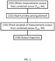
- a method for providing a diagnostic on the combined humidity and temperature sensing device described above can comprise a step 101 of obtaining a first local temperature T cell,1 and a first relative humidity RH 1 output by the combined humidity and temperature sensing device.
- these measurements can be realized essentially simultaneously, or at least close enough in time, such that relative humidity can be output as a function of temperature.
- the method can further comprise, after step 101, for instance after a set predefined time has passed, a step 102 of outputting a command to heat up the humidity sensing element using the heating means.
- step 101 for instance after a set predefined time has passed, a step 102 of outputting a command to heat up the humidity sensing element using the heating means.
- the method can further comprise a step 103 of checking variations between a local temperature and a local relative humidity measured after heating the humidity sensing element and the corresponding values measured before heating the humidity sensing element.
- This step can, therefore, comprise obtaining a second local temperature T cell,2 and a second local relative humidity RH 2 output by the combined humidity and temperature sensing device after performing step 102 of heating the humidity sensing element using the heating means.
- the second measurements can be carried out after a predetermined amount of time has passed following the initiation of the heating in step 102.
- the method can finally comprise a step 104 of outputting a diagnostic comprising information representative of a condition of the humidity sensing means based on results of the determinations in step 103.
- a diagnostic comprising information representative of a condition of the humidity sensing means based on results of the determinations in step 103.
- the diagnostic in step 104 can comprise, optionally, information representative that the temperature sensing means is functioning as expected.
- the diagnostic in step 104 can comprise, optionally, information representative that the humidity sensing means and the heating means are also functioning as expected.
- the diagnostic in step 104 can comprise information representative that the humidity sensing means is malfunctioning or at least likely to be malfunctioning.
- step 104 Further optional diagnostics output in step 104 can be based on results of the determinations in step 103. For instance, if it is determined that, contrary to expectations, no significant temperature increase has occurred after step 102, or that the temperature difference ⁇ T cell is below the predetermined temperature difference threshold indicative of a significant variation in temperature, the following optional diagnostics could be provided in step 104: If no reference temperature is available to verify whether the temperature sensing means of the combined humidity and temperature sensing device is functioning as expected or not, and if it is determined that, according to expectations, a significant corresponding drop in local relative humidity has actually occurred after step 102, or that the relative humidity difference ⁇ RH is above the predetermined relative humidity difference threshold indicative of a significant variation humidity, the diagnostic in step 104 can comprise, information that the temperature sensing means is malfunctioning or at least likely to be malfunctioning.
- the diagnostic in step 104 can comprise information representative that the heating means is malfunctioning or at least likely to be malfunctioning.
- a suspicion that the temperature sensing means could be malfunctioning of the combined humidity and temperature sensing device suspicions could be confirmed using, for instance, a reference temperature and/or an external separate temperature sensor.
- the heating means is the malfunctioning element.
- the method can further comprise a step of stopping an activity of the heating means, for instance in order to prevent possible future damage of the humidity sensing element.
- a diagnostic will be provided on a combined humidity and temperature sensing device comprising humidity sensing means, temperature sensing means, and heating means essentially as described above in relation to the first embodiment illustrated in FIG. 1 .
- additional temperature sensing means are also provided, different from the temperature sensing means of the combined humidity and temperature sensing device.
- the additional temperature sensing means is arranged and configured for measuring an ambient temperature, T air , outside of the combined humidity and temperature sensing device.
- the additional temperature sensing means is arranged such that the measured ambient temperature T air can be representative of an ambient temperature in a vicinity of the combined humidity and temperature sensing device.
- a method for providing a diagnostic on the combined humidity and temperature sensing device described above can comprise a series of optional steps to be carried out before the method steps described in the first embodiment in relation to the block diagram of FIG. 1 .
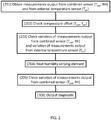
- the method comprises a step 201 of obtaining an external temperature T air output from the additional external temperature sensing means.
- a local temperature T cell can also be obtained from the temperature sensing means of the combined humidity and temperature sensing device (it is understood that a local relative humidity RH could also be obtaining the step).
- these measurements can be realized essentially simultaneously, or at least close enough in time, such that the operation conditions are essentially the same.
- this difference does not need to be an absolute value.
- a diagnostic could then output information that both temperature sensing means seem to be working as expected.
- the method steps described in relation to the embodiment illustrated in FIG. 1 could then be performed, using for instance the measurements obtained for the local temperature T cell and relative humidity RH in step 201 as the first temperature and first relative humidity in step 101 of the previous embodiment. In this case, it is essentially determined that the temperature sensing means of the combined humidity and temperature sensing device should be functioning as expected.
- this diagnostic regarding the temperature sensing means of the combined humidity and temperature sensing device could be used to check if another element of the combined sensor is malfunctioning and, accordingly, provide a diagnostic in step 104 as described above in relation to the method illustrated in FIG. 1
- the temperature difference ⁇ T is greater than a predetermined temperature difference threshold
- at least a suspicion of a possibly malfunctioning temperature sensor could be raised in respect of the external temperature sensing means and of the temperature sensing means of the combined humidity and temperature sensing device.
- the defective temperature sensor could then be identified using, for instance, a temperature reference to be compared to the local temperature T cell and to the ambient temperature T air . Then, the method steps of the previous embodiment illustrated in FIG. 1 could be carried out as described above.
- the temperature difference ⁇ T is greater than a predetermined temperature difference threshold, and no temperature reference is available, only a suspicion of a possibly malfunctioning temperature sensor may be raised. The suspicion could be output as part of diagnostic information resulting of the comparison between the measured external and local temperatures.
- the local relative humidity RH can also be considered to be a first local relative humidity RH 1 .
- these measurements are performed preferably before at least the step of the inventive method of heating the humidity sensing means, described for instance in relation to step 102 of the embodiment illustrated in FIG. 1 . In fact, these measurements can preferably be performed even before the step of measuring the first temperature and relative humidity describing relation to step 101 of the previous embodiment.
- step 203 can comprise obtaining a second ambient temperature T air,2 , a second local temperature T cell,2 , as well as a second local relative humidity RH 2 output by the external temperature sensing means and by the combined humidity and temperature sensing device, respectively.
- these second measurements can be carried out after a predetermined amount of time has passed following the first measurements carried out in step 201.
- , between the first and second local temperatures, ⁇ T cell
- , and between the first and second relative humidity, ⁇ RH
- these differences do not need to be absolute values.
- Conditions can then be determined to continue with the method steps described above in relation to the embodiment illustrated in FIG. 1 .
- step 203 if it is determined in step 203 that there has been essentially no variation in ambient temperature or that a variation in ambient temperature ⁇ T air is below a predefined significance threshold, and that there has been essentially no variation in local temperature or that a variation in local temperature ⁇ T cell is below a predefined significance threshold, which can be the same or different as the predefined significant threshold for ambient temperature, and that there has been essentially no variation in local relative humidity or that a variation in local relative humidity ⁇ RH is below a predefined significance threshold, then the method can proceed to a step 204, also illustrated in FIG.
- step 203 of heating the humidity sensing element using the heating means, corresponding essentially to step 102 in the previous embodiment illustrated in FIG. 1 .
- the second local temperature and the second local relative humidity obtained in step 203 could be used as the first local temperature and first local relative humidity in step 101.
- new measurements of the local temperature and relative humidity could be performed, as described essentially in relation to step 101 in the previous embodiment.
- the method can also comprise a step 205 of checking variations of the local temperature and relative humidity between the measurements performed before step 204 and new values measured after step 204.
- step 205 can correspond essentially to step 103 in the previous embodiment.
- the method can also comprise a subsequent step 206 of outputting a diagnostic based on the determinations made in step 205.
- This step can correspond essentially to step 104 in the embodiment illustrated in FIG. 1 .
- the diagnostic output in step 206 could also comprise outputting information that the combined humidity and temperature sensing device is switched to a degraded mode. Then, in the degraded mode, the combined humidity and temperature sensing device could output the measured relative humidity RH as a function of the ambient temperature T air measured by the external temperature sensing means rather than the local temperature T cell output by the malfunctioning temperature sensing means. In this way, a user could still receive at least some degree of usable information.
- steps 101 or 201 could be preceded by or could comprise waiting a predetermined amount of time. For instance, in systems requiring a certain amount of time before being stabilized, it could be advantageous to only start a full diagnostic, in particular a full in-range diagnostic, only after a predefined startup cycle.
- the method could allow performing a full diagnostic, in particular a full in-range diagnostic, over a certain period of time, for instance a period of activity of a system in which the method is used. Cycles could be repeated a predefined number of times and/or could be separated by a predefined amount of time.
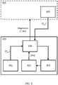
- the inventive method can be implemented in a system having a combined humidity and temperature sensing device 300 comprising a temperature sensor 301 (or temperature sensing means), a humidity sensor 302 (or humidity sensing means), and a heating unit 303 (or heating means), wherein the system also comprises an additional temperature sensor 305 different from the temperature sensor 301.
- the humidity sensor 302 can comprise a humidity sensing cell (or humidity sensing element), and is configured for measuring and outputting a local relative humidity, RH.
- the temperature sensor 301 can be arranged and configured for measuring a local temperature, T cell , in a vicinity of the humidity sensor 302, in particular in a vicinity of the humidity sensing cell.
- the temperature sensor 301 can, therefore, be affected by local temperature variations around the humidity sensor 302, whether natural or caused by the heating unit 303, as explained hereafter.
- the temperature sensor 301 can output a temperature which can be representative of the immediate environment of the humidity sensor 302, or even, if so desired, of the humidity sensing cell of the humidity sensor 302.
- the combined humidity and temperature sensing device 300 can be configured to output the measured local temperature T cell and/or the measured relative humidity RH, for instance towards a customer system 306 using the combined humidity and temperature sensing device 300.
- the heating unit 303 can be arranged and configured for heating the humidity sensing cell of the humidity sensor 302, and such that a local temperature variation caused by the heating unit 303 can be detected by the temperature sensor 301 under normal operation conditions.
- the heating unit 303 could be arranged and configured for heating also, directly or indirectly, the temperature sensing cell of the temperature sensor 301.
- the combined humidity and temperature sensing device 300 could be configured so that respective validity ranges can be predefined for the measured local temperature T cell and relative humidity RH, for instance as required by the customer system 306.
- the present invention does not have to be limited to in-range diagnostics and can be generally used for diagnosing an operation of the combined humidity and temperature sensing device 300.
- the additional temperature sensor 305 can be arranged and configured for measuring an ambient temperature, T air , which can be representative of a larger environment in the surroundings of the humidity sensor 302, for instance outside of the combined humidity and temperature sensing device 300, such that it is not influenced by local variations of temperature caused by the heating unit 303.
- T air an ambient temperature
- the additional temperature sensor 305 can be arranged such that the measured ambient temperature T air can be representative of an ambient temperature in a vicinity of the combined humidity and temperature sensing device 300, such that, when the heating unit 303 is not active, the temperatures output by the temperature sensor 301 and the additional temperature sensor 305 can be expected to be substantially similar. As illustrated in FIG.
- the additional temperature sensor 305 could be provided as an element of an external system, for instance the customer system 306, which could be configured for receiving outputs of the additional temperature sensor 305 and of the combined humidity and temperature sensing device 300. While, in this embodiment, the additional temperature sensor 305 is arranged outside of the combined humidity and temperature sensing device 300, in other embodiments, it could be provided in the combined humidity and temperature sensing device 300, sufficiently spaced apart and/or shielded from the heating unit 303.
- the system can further comprise a processing unit 304 (or processing means) configured for performing the inventive method and/or any of its variants, in particular for performing any of the variants described in relation to the embodiments illustrated in FIGS. 1 and 2 .
- a processing unit 304 or processing means configured for performing the inventive method and/or any of its variants, in particular for performing any of the variants described in relation to the embodiments illustrated in FIGS. 1 and 2 .
- the processing unit 304 could still be configured for performing the variants of the inventive method described in relation to the embodiment illustrated in FIG. 1 .
- the processing unit 304 can be configured, in particular, for receiving the local temperature T cell output from the temperature sensor 301 and the local relative humidity RH output from the humidity sensor 302. Accordingly, in preferred embodiments, the processing unit 304 can be provided as an integral part of the combined humidity and temperature sensing device 300.
- the processing unit 304 can also be configured for controlling the heating unit 303, in particular for activating or stopping the heating unit 303 so as to initiate or stop heating of the humidity sensing cell of the humidity sensor 302, and when applicable also of the temperature cell of the temperature sensor 301. Furthermore, as the case may be, the processing unit 304 can also be configured for receiving an ambient temperature T air output from the additional temperature sensor 305.
- the combined humidity and temperature sensing device 300 in particular its processing unit 304, can also be configured for outputting diagnostic information representative of a condition of the temperature sensor 301 and/or of the humidity sensor 302 and/or of the heating unit 303.
- the processing unit 304 could even be configured for outputting degraded information to the customer system 306, for instance following a determination that the temperature sensor 301 may be malfunctioning.
- the combined humidity and temperature sensor 300, and in particular the processing unit 304 could replace the local temperature T cell with the ambient temperature T air .
- both temperatures T cell , T air could be output together with a relative humidity RH, with an indication that the local temperature T cell has failed a diagnostic, in particular an in-range diagnostic.
- the processing unit 304 could be configured for controlling a calibration and/or for performing an auto-calibration of the combined humidity and temperature sensing device 300 based on results of the determinations in the method steps.
- the invention will be used for providing an in-range diagnostic when the system described in the embodiment illustrated in FIG. 4 is used in a motor vehicle, in particular in a system or in a subsystem of the vehicle's engine.
- the customer system 306 and the combined humidity and temperature sensing device 300 could be configured such that local temperatures, T cell , measured by the temperature sensor 301 and ambient temperatures, T air , measured by the additional temperature sensor 305 can be considered valid within a respective predefined temperature validity range.
- T cell local temperatures
- T air ambient temperatures
- T air ambient temperatures
- a validity range 0 °C ⁇ T cell , T air ⁇ 60 °C, can be adopted for both temperature sensors 301 and 305.
- the customer system 306 and the combined humidity and temperature sensing device 300 could also be configured such that a local relative humidity, RH, measured by the humidity sensor 302 can be considered valid within a predefined relative humidity validity range.
- RH a local relative humidity
- 30 % ⁇ RH ⁇ 80 % can be a validity range adopted for the humidity sensor 302.
- a full in-range diagnostic is not performed after startup of the vehicle's engine for a stabilization period of about 30 min. Then, according to a further variant of the invention, full in-range diagnostics are performed as long as the engine is running, for instance every minute. The output of each diagnostic is sent to the customer system 306, for instance a vehicle onboard computer.
- the processing unit 304 can be configured for performing any of the method steps described previously.
- the step 204 of controlling the heating unit 303 to heat up the humidity sensing element of the humidity sensor 302 could be triggered based on the relevance of the variations determined in step 203.
- the step 204 could be triggered by the processing unit 304 if the processing unit 304 has determined, in step 203, that ⁇ T air ⁇ 1 °C, and ⁇ T cell ⁇ 1 °C, and ⁇ RH ⁇ 2 % in the last 5s.
- the processing unit 304 could output a diagnostic based on which the activity of the heating unit 303 could be stopped, and/or a degraded mode could be triggered, and/or calibration modes could be triggered, and/or further in-range diagnostic cycles could be triggered.
- the present invention provides a solution for performing in-range diagnostics for combined humidity and temperature sensing devices with heating means as used in engine systems in the automotive industry.
- the present invention can be used essentially in any combined humidity and temperature sensing device with heating means arranged and configured for heating a humidity sensing element of the combined humidity and temperature sensing device.
- the present invention does not have to be limited only to in-range diagnostics.
Description
- The present application relates to a method for performing an in-range diagnostic on a combined humidity and temperature sensor, in particular to determine the validity or relevance of a measurement in a combined humidity and temperature sensor.
- In the automotive industry, on-board diagnostic (OBD) systems are commonly used for providing self-diagnostics capabilities for various vehicle components. For instance, OBD systems can provide real-time information regarding the status of a particular vehicle component or subsystem to a user of the vehicle, or to a technician during a maintenance operation. In some countries or regions, certain types of self-diagnostics can be compulsory upon request by local or regional environmental protection agencies, and a lack thereof may result in a fine.
- Some self-diagnostics were previously limited to out-of-range diagnostics, namely diagnostics of when sensing elements would perform a detection outputting a value outside of a predefined validity range. It is, however, more and more requested by environmental protection agencies and the automotive industry to provide in-range diagnostic capabilities. As opposed to an out-of-range diagnostic, an in-range diagnostic corresponds to a detection performed on a sensor's output when the output value is within the predefined validity range but is incorrect according to current application conditions. For example, assuming application conditions in which a current measurable temperature would be 20 °C, and a temperature sensor configured to measure temperatures between 0 °C and 60 °C, a temperature of 40 °C output by the temperature sensor would fall in the expected range of measurable temperatures but would be incorrect and, therefore, irrelevant to the current application conditions.
-
JP2001227790 - Furthermore, also in the automotive industry, it is known to use humidity sensors for measuring humidity in an air intake of an internal combustion engine. Typically, as described for instance in
US 2004/0237646 A1 , such humidity sensors can comprise a heating element used for heating and thereby cleaning the humidity sensing element of the humidity sensor. It is also known to combine these humidity sensors with a temperature sensor to measure a temperature in the vicinity of the humidity sensing element. - In the automotive industry, vehicles may have more than one temperature sensor. It is therefore known to perform in-range diagnostics on a given temperature sensor by comparing its output values with the values output by other temperature sensors, for instance other temperature sensors arranged in nearby areas of the vehicle. While this method could also be applied in order to identify a malfunctioning humidity sensor, it is not considered a cost efficient method. Methods of diagnosing the rationality of a humidity sensor output signal are known, for instance from
US 9 224 252 B1 - Thus, there is a need in the automotive industry for improved in-range diagnostic methods for humidity sensors, in particular for combined humidity and temperature sensors having a heating element.
- The above-mentioned problem is solved by a method according to claim 1, and by a system according to claim 11.
- Optional features of the method and system according to the invention are described in the dependent claims and will also be explained hereafter.
- According to the present invention, a method is provided for realizing a diagnostic on a combined humidity and temperature sensing device comprising humidity sensing means, temperature sensing means, and heating means arranged and configured for heating a humidity sensing element of the humidity sensing means. In such a combined humidity and temperature sensing device, the temperature sensing means can be preferable arranged and configured for measuring temperature in vicinity, in particular in close vicinity, of the humidity sensing means. The method comprises, in particular, steps of obtaining a first temperature and a first relative humidity output by the combined humidity and temperature sensing device, then heating the humidity sensing element, and then obtaining a second temperature and a second relative humidity output by the combined humidity and temperature sensing device.
- Furthermore, the method also comprises steps of determining a difference between the first temperature and the second temperature, and determining a difference between the first relative humidity and the second relative humidity. Then, based on a result of these determinations, when the difference between the first temperature and the second temperature is higher than a predetermined temperature difference threshold, and the difference between the first relative humidity and the second relative humidity is lower than a predetermined humidity difference threshold, the method further comprises outputting diagnostic information representative of a condition of the humidity sensing means, in particular of a possible malfunction of the humidity sensing means.
- The heating element in the combined humidity and temperature sensing device allows introducing local increases of temperature on the humidity sensing element of the combined humidity and temperature sensing device, thereby affecting humidity locally as well. Since the temperature sensing means of a combined humidity and temperature sensing device can be arranged and configured for measuring temperatures in the vicinity of the humidity sensing means, under normal operation conditions, local variations of temperature affecting the humidity sensing means can be expected to affect also the temperature sensing means. Variations measured on humidity and temperature sensing elements can then be used to determine a possible failure. Thus, based on a comparison of temperature and relative humidity measurements performed before and after heating the humidity sensing element, or in other words based on temperature and relative humidity variations before and after the heating step, the method of the present invention allows diagnosing whether the humidity sensing means of a combined humidity and temperature sensing device could be malfunctioning. This is particularly advantageous to perform in-range diagnostics, that is, when a combined humidity and temperature sensing device outputs measurements within a predefined validity range but actually incorrect in view of current application conditions.
- In some embodiments, the method can further comprise, based on a result of the above-mentioned determinations, when the difference between the first temperature and the second temperature is lower than the predetermined temperature difference threshold, and the difference between the first relative humidity and the second relative humidity is higher than the predetermined humidity difference threshold, outputting diagnostic information representative of a condition of the temperature sensing means, in particular of a possible malfunction of the temperature sensing means. Thus, also based on the result of temperature and relative humidity variations before and after the heating step, the inventive method can also diagnosing whether the temperature sensing means of a combined humidity and temperature sensing device could be malfunctioning.
- In some embodiments, the method can further comprise, based on the result of the above-mentioned determinations, when the difference between the first temperature and the second temperature is lower than the predetermined temperature difference threshold, and the difference between the first relative humidity and the second relative humidity is lower than the predetermined humidity difference threshold, outputting diagnostic information representative of a condition of the heating means, in particular of a possible malfunction of the heating means. In this variant, the heating element can be diagnosed essentially if no modifications are observed on both humidity and temperature measurements or if these variations are considered to be irrelevant. Thus, still based on the result of temperature and relative humidity variations before and after the heating step, the inventive method can even allow diagnosing whether the heating element of a combined humidity and temperature sensing device could be malfunctioning.
- In some embodiments, when any of the previous variants are combined, the present invention has the advantage that the three main components of a combined humidity and temperature sensing device can be diagnosed, namely the humidity sensor, the temperature sensor, and even the heating element of the humidity sensor. Thus, any of these variants is particularly advantageous when performing in-range diagnostics of measurements output by a combined humidity and temperature sensing device.
- In a variant of this embodiment, the method can further comprise outputting a command for stopping an activity of the heating means. In a situation where the heating element of a combined humidity and temperature sensing device could be malfunctioning, the present invention can be advantageous to stop a function of the heating element and thereby prevent further malfunctions and even damaging of a humidity sensor.
- In the invention, before heating the humidity sensing means, in particular before measuring the first temperature and relative humidity with the combined humidity and temperature sensing device, the method further comprises steps of obtaining an external temperature output from an additional temperature sensing means different from the temperature sensing means of the combined humidity and temperature sensing device, obtaining a local temperature output from the combined humidity and temperature sensing device. In particular, obtaining the external temperature could relate to obtaining a temperature from an additional temperature sensing means that is not influenced by local variations of temperature caused by the heating means in vicinity of the humidity sensing means. In other words, the external temperature could relate to a temperature that is representative of local conditions near the humidity sensing means but that is not representative of the condition of the humidity sensing means itself. This could be achieved using additional temperature means external to the combined humidity and temperature sensing device, or internal to the combined humidity and temperature sensing device but arranged sufficiently spaced apart or shielded from the heating means. Then, when a difference between the external temperature and the local temperature is above a predetermined temperature difference threshold, the method can further comprise outputting diagnostic information representative of a condition of either of the additional temperature sensing means or the combined humidity sensing device, in particular comprising a suspicion of a possible malfunction of either of the additional temperature sensing means or the combined humidity and temperature sensing device, more in particular or of the temperature sensing means of the combined humidity and temperature sensing device. This variant is particularly advantageous in a system comprising at least another temperature sensor, different from the temperature sensor of the combined humidity and temperature sensing device, for instance like in engine systems of motor vehicles. Thus, temperatures can be measured internally to the combined humidity and temperature sensor, close to the humidity sensing element, and outside the combined sensor or at least not in the immediate surroundings of the humidity sensing element, which allows comparing these measurements and detecting an offset between them. The invention then allows at least the raising a suspicion that one of the temperature sensors may be malfunctioning.
- In further preferred embodiments, before heating the humidity sensing means, in particular before measuring the first temperature and relative humidity with the combined humidity and temperature sensing device, the method can further comprise steps of obtaining a first external temperature output from an additional temperature sensing means different from the temperature sensing means of the combined humidity and temperature sensing device, obtaining a first local temperature and a first relative humidity output from the combined humidity and temperature sensing device. When a difference between the first external temperature and the first local temperature is above a first predetermined temperature difference threshold, after a predetermined period of time, the method can then comprise obtaining a second external temperature output from the additional temperature sensing means, obtaining a second local temperature and a second relative humidity output from the combined humidity and temperature sensing device, determining whether a variation between the first external temperature and the second external temperature and a variation between the first local temperature and the second local temperature are both below a second predetermined temperature difference threshold, and determining whether a variation between the first relative humidity and the second relative humidity is below a predetermined humidity difference threshold.
- Some systems may provide a reference temperature, which may be an output of yet another temperature sensor, and which may be usable to distinguish which of the additional temperature sensor or of the temperature sensor belonging to the combined humidity and temperature sensing device could be malfunctioning. The present invention has the advantage that it may also distinguish which temperature sensor may be malfunctioning even without a reference temperature.
- In a variant of embodiments comprising the prior steps related to an additional temperature sensing means, the method described above and its variants can be carried out only when said variation between said first external temperature and second external temperature and said variation between said first local temperature and second local temperature are both determined to be below said second predetermined temperature difference threshold, and said variation between said first relative humidity and second relative humidity is also determined to be below said predetermined humidity difference threshold.
- Thus, when a suspicion of a possibly malfunctioning temperature sensor is raised regarding either of the additional temperature sensor or the temperature sensor of the combined humidity and temperature sensing device, based on a result of variations over a predetermined amount of time of the temperature output by the additional temperature sensor, and of the temperature and relative humidity output by the combined humidity and temperature sensing device, it is possible to further proceed with the various steps of the inventive method described above, including any of the optional variants to perform a full diagnostic, in particular a full in-range diagnostic.
- In a variant of embodiments comprising the prior steps related to an additional temperature sensing means, when a possible malfunction of the temperature sensing means of the combined humidity and temperature sensing device is detected, the method can comprise outputting degraded mode information comprising a relative humidity output by the combined humidity and temperature sensing device, and a temperature output by the additional temperature sensing means. Thus, when an output of the diagnostic is that the temperature sensing means of the combined humidity and temperature sensing device could be malfunctioning, a user of the system may still be able to retrieve humidity and temperature information, wherein the temperature information will be based, for instance, on an output of the additional temperature sensing means.
- In further preferred embodiments, before any of the steps of the variants described above, the method can further comprise waiting a predetermined amount of time, in particular corresponding to a predefined startup or stabilization time of a system using said combined humidity and temperature sensing device. This variant is particularly advantageous in systems which require a stabilization time before carrying out any in-range diagnostic of temperature and/or humidity. Thus, this variant may be particularly advantageous for engine systems of motor vehicles, wherein, before starting the first cycle of in-range diagnostics after startup of the engine, the method steps described above could be preceded by a predefined waiting time corresponding to a stabilization time of the engine.
- Preferably, the inventive method and its variants can be carried out only when temperature and relative humidity are measured within a respective predetermined validity range of temperature and relative humidity. In this manner, if desired the method can be limited specifically to in-range diagnostics performed on in-range temperature and/or humidity values.
- In some embodiments, the method can further comprise cycling through the method steps of any of the variants described above a predefined number of times. In variants of these embodiments, each cycle can be performed a predefined amount of time after a previous cycle. In this manner, it is possible to deliver a diagnostic in a regular manner.
- According to the present invention, the above-mentioned problem is also solved by a system comprising a combined humidity and temperature sensing device comprising temperature sensing means, humidity sensing means, and heating means arranged and configured for heating a humidity sensing element of the humidity sensing means, as well as additional temperature sensing means different from the temperature sensing means of the combined humidity and temperature sensing device. In such a combined humidity and temperature sensing device, the temperature sensing means can be preferable arranged and configured for measuring temperature in vicinity, in particular in close vicinity, of the humidity sensing means. In turn, the additional temperature sensing means can be arranged and configured so as not to be influenced by local variations of temperature caused by the heating means in vicinity of the humidity sensing means. In other words, the additional temperature sensing means could output temperatures representative of local conditions in the surroundings of the humidity sensing means but not representative of the condition of the humidity sensing means itself or of a close vicinity thereof. The system, in particular the combined humidity and temperature sensing device, further comprises processing means configured to perform any variant of the inventive method. Depending on the configuration, the system would then provide the various advantageous effects described above.
- In any case, the method and system of the present invention can be used more in general for performing a diagnostic on any type of humidity sensor combined with a heating element and a temperature sensor. Specifically, in the automotive industry, the method and system of the present invention can be used during the driving cycle of a vehicle, as well as during maintenance operations, with the beneficial advantage of solving the aforementioned problems. The present invention could also be applied to broader fields such as Industrial and Commercial Transportation (ICT).
- The invention will be described more in detail hereafter, based on advantageous embodiments described in combination with the following figures:
- FIG. 1
- is a simplified bloc diagram illustrating an example method for providing a diagnostic on a combined humidity and temperature sensing device;
- FIG. 2
- is a simplified bloc diagram illustrating another embodiment of the inventive method for providing a diagnostic on a combined humidity and temperature sensing device; and
- FIG. 3
- schematically illustrates a system configured for implementing the inventive method for providing a diagnostic on a combined humidity and temperature sensing device, in a further embodiment.
- In the following, the method according to the present invention will be explained in combination with embodiments illustrated in
FIG. 2 , wherein a diagnostic will be provided on a combined humidity and temperature sensing device comprising humidity sensing means, temperature sensing means, and heating means. - Preferably, the humidity sensing means comprises a humidity sensing element, and is configured for measuring and outputting a local relative humidity, RH. Preferably, the temperature sensing means is arranged and configured for measuring a local temperature, Tcell, in a vicinity of the humidity sensing means, in particular in a vicinity of the humidity sensing element. Preferably, the heating element is arranged and configured for heating the humidity sensing element of the humidity sensing means. Optionally, the combined humidity and temperature sensing device could be configured so that respective validity ranges can be predefined for the measured local temperature Tcell and relative humidity RH. However, the present invention does not have to be limited to in-range diagnostics and can be generally used to diagnose the operation of the combined humidity and temperature sensing device.
- As can be taken from the block diagram of
FIG. 1 , a method for providing a diagnostic on the combined humidity and temperature sensing device described above can comprise astep 101 of obtaining a first local temperature Tcell,1 and a first relative humidity RH1 output by the combined humidity and temperature sensing device. Preferably, these measurements can be realized essentially simultaneously, or at least close enough in time, such that relative humidity can be output as a function of temperature. - Furthermore, as also illustrated in
FIG. 1 , the method can further comprise, afterstep 101, for instance after a set predefined time has passed, astep 102 of outputting a command to heat up the humidity sensing element using the heating means. As a result, an increase in the local temperature Tcell and a decrease in the local relative humidity RH are expected if all elements of the combined humidity and temperature sensing device are operating correctly. - Then, as can also be taken from
FIG. 1 , afterstep 102, the method can further comprise astep 103 of checking variations between a local temperature and a local relative humidity measured after heating the humidity sensing element and the corresponding values measured before heating the humidity sensing element. This step can, therefore, comprise obtaining a second local temperature Tcell,2 and a second local relative humidity RH2 output by the combined humidity and temperature sensing device after performingstep 102 of heating the humidity sensing element using the heating means. Preferably, the second measurements can be carried out after a predetermined amount of time has passed following the initiation of the heating instep 102. - Furthermore, in
step 103, a difference can then be determined between the first local temperature Tcell,1 and the second local temperature Tcell,2, for instance ΔTcell = |Tcell,2 - Tcell,1|. Similarly, a difference can then be determined between the first local relative humidity RH1 and the second local relative humidity RH2, for instance ΔRH = |RH2 - RH1|. It should be noted that, depending on the embodiments, these differences do not need to be absolute values. - In any case, as also illustrated in
FIG. 1 , the method can finally comprise astep 104 of outputting a diagnostic comprising information representative of a condition of the humidity sensing means based on results of the determinations instep 103. In this respect:
If it is determined that, according to expectations, a significant temperature increase has indeed occurred afterstep 102, or that the temperature difference ΔTcell is above a predetermined temperature difference threshold indicative of a significant variation in temperature, the diagnostic instep 104 can comprise, optionally, information representative that the temperature sensing means is functioning as expected. - Furthermore, when it is determined that a significant temperature increase has occurred, if it is also determined that, also according to expectations, a significant corresponding drop in local relative humidity has indeed occurred after
step 102, or that the relative humidity difference ΔRH is also above a predetermined relative humidity difference threshold indicative of a significant variation humidity, the diagnostic instep 104 can comprise, optionally, information representative that the humidity sensing means and the heating means are also functioning as expected. - However, when it is determined that a significant temperature increase has occurred as expected after
step 102, if it is determined that, contrary to expectations, no corresponding drop in local relative humidity has occurred afterstep 102, or that the relative humidity difference ΔRH is, in fact, below the predetermined relative humidity difference threshold indicative of a significant variation humidity, the diagnostic instep 104 can comprise information representative that the humidity sensing means is malfunctioning or at least likely to be malfunctioning. - Further optional diagnostics output in
step 104 can be based on results of the determinations instep 103. For instance, if it is determined that, contrary to expectations, no significant temperature increase has occurred afterstep 102, or that the temperature difference ΔTcell is below the predetermined temperature difference threshold indicative of a significant variation in temperature, the following optional diagnostics could be provided in step 104:
If no reference temperature is available to verify whether the temperature sensing means of the combined humidity and temperature sensing device is functioning as expected or not, and if it is determined that, according to expectations, a significant corresponding drop in local relative humidity has actually occurred afterstep 102, or that the relative humidity difference ΔRH is above the predetermined relative humidity difference threshold indicative of a significant variation humidity, the diagnostic instep 104 can comprise, information that the temperature sensing means is malfunctioning or at least likely to be malfunctioning. - However, if it is determined that, contrary to expectations, no drop in local relative humidity has occurred after
step 102, or that the relative humidity difference ΔRH is, in fact, below the predetermined relative humidity difference threshold indicative of a significant variation humidity, the diagnostic instep 104 can comprise information representative that the heating means is malfunctioning or at least likely to be malfunctioning. - Optionally, a suspicion that the temperature sensing means could be malfunctioning of the combined humidity and temperature sensing device suspicions could be confirmed using, for instance, a reference temperature and/or an external separate temperature sensor. In this case, depending on the result of this confirmation, it could also be confirmed that, on the contrary, rather than the temperature sensing means, the heating means is the malfunctioning element. Also optionally, based on a diagnostic in
step 104 comprising information representative of a suspicion and/or a confirmation that the heating means is malfunctioning, the method can further comprise a step of stopping an activity of the heating means, for instance in order to prevent possible future damage of the humidity sensing element. - The inventive method will now be described in combination with the embodiment illustrated in
FIG. 2 . In this embodiment, a diagnostic will be provided on a combined humidity and temperature sensing device comprising humidity sensing means, temperature sensing means, and heating means essentially as described above in relation to the first embodiment illustrated inFIG. 1 . However, in addition, in this embodiment, additional temperature sensing means are also provided, different from the temperature sensing means of the combined humidity and temperature sensing device. - Preferably, the additional temperature sensing means is arranged and configured for measuring an ambient temperature, Tair, outside of the combined humidity and temperature sensing device. Preferably, the additional temperature sensing means is arranged such that the measured ambient temperature Tair can be representative of an ambient temperature in a vicinity of the combined humidity and temperature sensing device.
- As can be taken from the block diagram of
FIG. 2 , according to a variant of an aspect of the present invention, a method for providing a diagnostic on the combined humidity and temperature sensing device described above can comprise a series of optional steps to be carried out before the method steps described in the first embodiment in relation to the block diagram ofFIG. 1 . - Thus, at least before heating the humidity sensing means, in particular like in
step 102 described above, the method comprises astep 201 of obtaining an external temperature Tair output from the additional external temperature sensing means. In this step, a local temperature Tcell can also be obtained from the temperature sensing means of the combined humidity and temperature sensing device (it is understood that a local relative humidity RH could also be obtaining the step). Preferably, these measurements can be realized essentially simultaneously, or at least close enough in time, such that the operation conditions are essentially the same. - Then, still before heating the humidity sensing means, the method comprises a
step 202 in which a difference between the local temperature Tcell and the external temperature Tair is determined, for instance ΔT = |Tcell - Tair|. Here again, it should be noted that, depending on the embodiments, this difference does not need to be an absolute value. - Here, if it is determined that the temperature difference ΔT is smaller than a predetermined temperature difference threshold, a diagnostic could then output information that both temperature sensing means seem to be working as expected. The method steps described in relation to the embodiment illustrated in
FIG. 1 could then be performed, using for instance the measurements obtained for the local temperature Tcell and relative humidity RH instep 201 as the first temperature and first relative humidity instep 101 of the previous embodiment. In this case, it is essentially determined that the temperature sensing means of the combined humidity and temperature sensing device should be functioning as expected. Thus, based on results of the determinations instep 103 described above, this diagnostic regarding the temperature sensing means of the combined humidity and temperature sensing device could be used to check if another element of the combined sensor is malfunctioning and, accordingly, provide a diagnostic instep 104 as described above in relation to the method illustrated inFIG. 1 - However, if it is determined that the temperature difference ΔT is greater than a predetermined temperature difference threshold, at least a suspicion of a possibly malfunctioning temperature sensor could be raised in respect of the external temperature sensing means and of the temperature sensing means of the combined humidity and temperature sensing device. The defective temperature sensor could then be identified using, for instance, a temperature reference to be compared to the local temperature Tcell and to the ambient temperature Tair. Then, the method steps of the previous embodiment illustrated in
FIG. 1 could be carried out as described above. - If it is determined that the temperature difference ΔT is greater than a predetermined temperature difference threshold, and no temperature reference is available, only a suspicion of a possibly malfunctioning temperature sensor may be raised. The suspicion could be output as part of diagnostic information resulting of the comparison between the measured external and local temperatures.
- Thus, in order to provide a more complete diagnostic it is determined that the temperature difference ΔT is greater than a predetermined temperature difference threshold, in the embodiment illustrated in
FIG. 2 , instep 201, it is also possible to consider that the external temperature Tair is a first external temperature Tair,1, and that the local temperature is a first local temperature Tcell,1. Accordingly, the local relative humidity RH can also be considered to be a first local relative humidity RH1. As explained above, these measurements are performed preferably before at least the step of the inventive method of heating the humidity sensing means, described for instance in relation to step 102 of the embodiment illustrated inFIG. 1 . In fact, these measurements can preferably be performed even before the step of measuring the first temperature and relative humidity describing relation to step 101 of the previous embodiment. - Then, when it is determined in
step 202 that the temperature difference ΔT = |Tcell,1 - Tair,1| between the first local temperature Tcell,1 and the first external temperature Tair,1 is greater than a predetermined temperature difference threshold, the method can further comprise asubsequent step 203 of checking variations, in particular dynamically, of the ambient or external temperature Tair, of the local temperature Tcell, and of the local relative humidity RH. Thus, step 203 can comprise obtaining a second ambient temperature Tair,2, a second local temperature Tcell,2, as well as a second local relative humidity RH2 output by the external temperature sensing means and by the combined humidity and temperature sensing device, respectively. Preferably, these second measurements can be carried out after a predetermined amount of time has passed following the first measurements carried out instep 201. - Furthermore, in
step 203, differences can then be determined between the first and second ambient temperatures, ΔTair = |Tair,2 - Tair,1|, between the first and second local temperatures, ΔTcell = |Tcell,2 - Tcell,1|, and between the first and second relative humidity, ΔRH = |RH2 - RH1|. Again, it should be noted that, depending on the embodiments, these differences do not need to be absolute values. - Conditions can then be determined to continue with the method steps described above in relation to the embodiment illustrated in
FIG. 1 . In particular, if it is determined instep 203 that there has been essentially no variation in ambient temperature or that a variation in ambient temperature ΔTair is below a predefined significance threshold, and that there has been essentially no variation in local temperature or that a variation in local temperature ΔTcell is below a predefined significance threshold, which can be the same or different as the predefined significant threshold for ambient temperature, and that there has been essentially no variation in local relative humidity or that a variation in local relative humidity ΔRH is below a predefined significance threshold, then the method can proceed to astep 204, also illustrated inFIG. 2 , of heating the humidity sensing element using the heating means, corresponding essentially to step 102 in the previous embodiment illustrated inFIG. 1 . Here, the second local temperature and the second local relative humidity obtained instep 203 could be used as the first local temperature and first local relative humidity instep 101. Alternatively, betweensteps - As can also be taken from
FIG. 2 , afterstep 204, the method can also comprise astep 205 of checking variations of the local temperature and relative humidity between the measurements performed beforestep 204 and new values measured afterstep 204. Thus, step 205 can correspond essentially to step 103 in the previous embodiment. - Furthermore, as also illustrated in
FIG. 2 , the method can also comprise asubsequent step 206 of outputting a diagnostic based on the determinations made instep 205. This step can correspond essentially to step 104 in the embodiment illustrated inFIG. 1 . - In the embodiment illustrated in
FIG. 2 , following any of the various steps described in relation toFIGS. 1 or2 , if it is determined that the temperature sensing means of the combined humidity and temperature sensing device is malfunctioning, the diagnostic output instep 206 could also comprise outputting information that the combined humidity and temperature sensing device is switched to a degraded mode. Then, in the degraded mode, the combined humidity and temperature sensing device could output the measured relative humidity RH as a function of the ambient temperature Tair measured by the external temperature sensing means rather than the local temperature Tcell output by the malfunctioning temperature sensing means. In this way, a user could still receive at least some degree of usable information. - Optionally, steps 101 or 201 could be preceded by or could comprise waiting a predetermined amount of time. For instance, in systems requiring a certain amount of time before being stabilized, it could be advantageous to only start a full diagnostic, in particular a full in-range diagnostic, only after a predefined startup cycle.
- Optionally, by cycling through the method steps described above, in any of the embodiments and variants thereof described in relation to
FIGS. 1 and2 , the method could allow performing a full diagnostic, in particular a full in-range diagnostic, over a certain period of time, for instance a period of activity of a system in which the method is used. Cycles could be repeated a predefined number of times and/or could be separated by a predefined amount of time. - Optionally, it could also be possible to use the inventive method and variants described in the embodiments illustrated in
FIGS. 1 and2 for controlling a calibration and/or for auto-calibration of the combined humidity and temperature sensing device. - Next, the general principle of the device according to the present invention will be explained in combination with the embodiment illustrated in
FIG. 3 . - As can be taken from
FIG. 3 , according to another aspect of the present invention, the inventive method can be implemented in a system having a combined humidity andtemperature sensing device 300 comprising a temperature sensor 301 (or temperature sensing means), a humidity sensor 302 (or humidity sensing means), and a heating unit 303 (or heating means), wherein the system also comprises anadditional temperature sensor 305 different from thetemperature sensor 301. - In particular, the
humidity sensor 302 can comprise a humidity sensing cell (or humidity sensing element), and is configured for measuring and outputting a local relative humidity, RH. Furthermore, thetemperature sensor 301 can be arranged and configured for measuring a local temperature, Tcell, in a vicinity of thehumidity sensor 302, in particular in a vicinity of the humidity sensing cell. Thetemperature sensor 301 can, therefore, be affected by local temperature variations around thehumidity sensor 302, whether natural or caused by theheating unit 303, as explained hereafter. Accordingly, thetemperature sensor 301 can output a temperature which can be representative of the immediate environment of thehumidity sensor 302, or even, if so desired, of the humidity sensing cell of thehumidity sensor 302. Thus, the combined humidity andtemperature sensing device 300 can be configured to output the measured local temperature Tcell and/or the measured relative humidity RH, for instance towards acustomer system 306 using the combined humidity andtemperature sensing device 300. - Furthermore, the
heating unit 303 can be arranged and configured for heating the humidity sensing cell of thehumidity sensor 302, and such that a local temperature variation caused by theheating unit 303 can be detected by thetemperature sensor 301 under normal operation conditions. For instance, theheating unit 303 could be arranged and configured for heating also, directly or indirectly, the temperature sensing cell of thetemperature sensor 301. Optionally, the combined humidity andtemperature sensing device 300 could be configured so that respective validity ranges can be predefined for the measured local temperature Tcell and relative humidity RH, for instance as required by thecustomer system 306. However, as explained above, the present invention does not have to be limited to in-range diagnostics and can be generally used for diagnosing an operation of the combined humidity andtemperature sensing device 300. - Furthermore, the
additional temperature sensor 305 can be arranged and configured for measuring an ambient temperature, Tair, which can be representative of a larger environment in the surroundings of thehumidity sensor 302, for instance outside of the combined humidity andtemperature sensing device 300, such that it is not influenced by local variations of temperature caused by theheating unit 303.. Preferably, theadditional temperature sensor 305 can be arranged such that the measured ambient temperature Tair can be representative of an ambient temperature in a vicinity of the combined humidity andtemperature sensing device 300, such that, when theheating unit 303 is not active, the temperatures output by thetemperature sensor 301 and theadditional temperature sensor 305 can be expected to be substantially similar. As illustrated inFIG. 3 , theadditional temperature sensor 305 could be provided as an element of an external system, for instance thecustomer system 306, which could be configured for receiving outputs of theadditional temperature sensor 305 and of the combined humidity andtemperature sensing device 300. While, in this embodiment, theadditional temperature sensor 305 is arranged outside of the combined humidity andtemperature sensing device 300, in other embodiments, it could be provided in the combined humidity andtemperature sensing device 300, sufficiently spaced apart and/or shielded from theheating unit 303. - As also illustrated in
FIG. 3 , according to an aspect of the invention, the system can further comprise a processing unit 304 (or processing means) configured for performing the inventive method and/or any of its variants, in particular for performing any of the variants described in relation to the embodiments illustrated inFIGS. 1 and2 . Here, it should be noted that in alternative embodiments without anadditional temperature sensor 305, theprocessing unit 304 could still be configured for performing the variants of the inventive method described in relation to the embodiment illustrated inFIG. 1 . - Thus, in any case, the
processing unit 304 can be configured, in particular, for receiving the local temperature Tcell output from thetemperature sensor 301 and the local relative humidity RH output from thehumidity sensor 302. Accordingly, in preferred embodiments, theprocessing unit 304 can be provided as an integral part of the combined humidity andtemperature sensing device 300. - As can also be taken from
FIG. 3 , advantageously, theprocessing unit 304 can also be configured for controlling theheating unit 303, in particular for activating or stopping theheating unit 303 so as to initiate or stop heating of the humidity sensing cell of thehumidity sensor 302, and when applicable also of the temperature cell of thetemperature sensor 301. Furthermore, as the case may be, theprocessing unit 304 can also be configured for receiving an ambient temperature Tair output from theadditional temperature sensor 305. - Furthermore, as illustrated in
FIG. 3 , the combined humidity andtemperature sensing device 300, in particular itsprocessing unit 304, can also be configured for outputting diagnostic information representative of a condition of thetemperature sensor 301 and/or of thehumidity sensor 302 and/or of theheating unit 303. - Optionally, as described above, the
processing unit 304 could even be configured for outputting degraded information to thecustomer system 306, for instance following a determination that thetemperature sensor 301 may be malfunctioning. In this situation, rather than outputting temperature and humidity information T, RH comprising the relative humidity RH measured by thehumidity sensor 302 and the local temperature Tcell measured by thetemperature sensor 301, in the degraded mode, the combined humidity andtemperature sensor 300, and in particular theprocessing unit 304, could replace the local temperature Tcell with the ambient temperature Tair. In other variants, both temperatures Tcell, Tair could be output together with a relative humidity RH, with an indication that the local temperature Tcell has failed a diagnostic, in particular an in-range diagnostic. - Optionally, the
processing unit 304 could be configured for controlling a calibration and/or for performing an auto-calibration of the combined humidity andtemperature sensing device 300 based on results of the determinations in the method steps. - An example will now be described in the context of automotive applications. However, it should be understood that the present invention is not limited to this particular context and could be applied, as the case may be, to any combined humidity and temperature sensing device of the type comprising heating means configured for heating a humidity sensing element of described above.
- In this example, the invention will be used for providing an in-range diagnostic when the system described in the embodiment illustrated in FIG. 4 is used in a motor vehicle, in particular in a system or in a subsystem of the vehicle's engine.
- Accordingly, by way of example and in a non-limitative manner, and following variants of the invention, the
customer system 306 and the combined humidity andtemperature sensing device 300 could be configured such that local temperatures, Tcell, measured by thetemperature sensor 301 and ambient temperatures, Tair, measured by theadditional temperature sensor 305 can be considered valid within a respective predefined temperature validity range. For the ease of comprehension, a same example of a validity range, 0 °C < Tcell, Tair < 60 °C, can be adopted for bothtemperature sensors - Similarly, the
customer system 306 and the combined humidity andtemperature sensing device 300 could also be configured such that a local relative humidity, RH, measured by thehumidity sensor 302 can be considered valid within a predefined relative humidity validity range. In this example, and also in a non-limitative manner, 30 % < RH < 80 % can be a validity range adopted for thehumidity sensor 302. - According to a variant of the invention, a full in-range diagnostic is not performed after startup of the vehicle's engine for a stabilization period of about 30 min. Then, according to a further variant of the invention, full in-range diagnostics are performed as long as the engine is running, for instance every minute. The output of each diagnostic is sent to the
customer system 306, for instance a vehicle onboard computer. - Since the
additional temperature sensor 305 is available in this example, theprocessing unit 304 can be configured for performing any of the method steps described previously. When performing thestep 202 of checking a temperature offset between the ambient and local temperatures, an identification of a defective temperature sensor could be launched, for instance, when ΔT = |Tcell,1 - Tair,1| > 10 °C. It is understood that this threshold may vary depending on application conditions, for instance on the arrangement of theadditional temperature sensor 305 with respect to the combined humidity andtemperature sensing device 300. - Furthermore, in this example, for a suspicion of a defective temperature sensor, namely when it is determined in
step 202 that ΔT > 10 °C, as explained above, thestep 204 of controlling theheating unit 303 to heat up the humidity sensing element of thehumidity sensor 302 could be triggered based on the relevance of the variations determined instep 203. For instance, thestep 204 could be triggered by theprocessing unit 304 if theprocessing unit 304 has determined, instep 203, that ΔTair < 1 °C, and ΔTcell < 1 °C, and ΔRH < 2 % in the last 5s. - Then, as described above, based on the diagnostic output by the
processing unit 304 instep 206, further actions could be triggered, in particular by theprocessing unit 304, in accordance with further preferred variants of the invention. For instance, as the case may be and a non-limitative manner, theprocessing unit 304 could output a diagnostic based on which the activity of theheating unit 303 could be stopped, and/or a degraded mode could be triggered, and/or calibration modes could be triggered, and/or further in-range diagnostic cycles could be triggered. - Thus, the present invention provides a solution for performing in-range diagnostics for combined humidity and temperature sensing devices with heating means as used in engine systems in the automotive industry. However, as can be taken from the various embodiments described above, the present invention can be used essentially in any combined humidity and temperature sensing device with heating means arranged and configured for heating a humidity sensing element of the combined humidity and temperature sensing device. Furthermore, the present invention does not have to be limited only to in-range diagnostics.
-
- 300
- combined humidity and temperature sensing device
- 301
- temperature sensor
- 302
- humidity sensor
- 303
- heating unit
- 304
- processing unit
- 305
- additional temperature sensor
- 306
- customer system
Claims (13)
- Method for providing a diagnostic on a combined humidity and temperature sensing device comprising humidity sensing means, temperature sensing means, and heating means arranged and configured for heating a humidity sensing element of the humidity sensing means, the method comprising:obtaining (101) a first temperature (Tcell,1) and a first relative humidity (RH1) output by the combined humidity and temperature sensing device; then heating (102) the humidity sensing element; and thenobtaining a second temperature (Tcell,2) and a second relative humidity (RH2) output by the combined humidity and temperature sensing device;determining a difference (ΔTcell) between the first temperature (Tcell,1) and the second temperature (Tcell,2); anddetermining a difference (ΔRH) between the first relative humidity (RH1) and the second relative humidity (RH2); then:when the difference (ΔTcell) between the first temperature (Tcell,1) and the second temperature (Tcell,2) is higher than a predetermined temperature difference threshold; andthe difference (ΔRH) between the first relative humidity (RH1) and the second relative humidity (RH2) is lower than a predetermined humidity difference threshold; outputting diagnostic information (104) representative of a condition of the humidity sensing means, in particular of a possible malfunction of the humidity sensing means;characterized in that the method further comprises before heating the humidity sensing means, in particular before measuring the first temperature and relative humidity with the combined humidity and temperature sensing device:obtaining an external temperature (Tair) output from an additional temperature sensing means different from the temperature sensing means of the combined humidity and temperature sensing device;obtaining a local temperature (Tcell) output from the combined humidity and temperature sensing device; andwhen a difference between the external temperature (Tair) and the local temperature (Tcell) is above a predetermined temperature difference threshold, outputting diagnostic information representative of a condition of either of the additional temperature sensing means or the combined humidity sensing device, in particular comprising a suspicion of a possible malfunction of either of the additional temperature sensing means or the combined humidity and temperature sensing device, more in particular or of the temperature sensing means of the combined humidity and temperature sensing device.
- Method according to claim 1, further comprising:when the difference (ΔTcell) between the first temperature (Tcell,1) and the second temperature (Tcell,2) is lower than the predetermined temperature difference threshold; andthe difference (ΔRH) between the first relative humidity (RH1) and the second relative humidity (RH2) is higher than the predetermined humidity difference threshold;outputting diagnostic information representative of a condition of the temperature sensing means, in particular of a possible malfunction of the temperature sensing means.
- Method according to any of claims 1 or 2, further comprising:when the difference (ΔTcell) between the first temperature (Tcell,1) and the second temperature (Tcell,2) is lower than the predetermined temperature difference threshold; andthe difference (ΔRH) between the first relative humidity (RH1) and the second relative humidity (RH2) is lower than the predetermined humidity difference threshold;outputting diagnostic information representative of a condition of the heating means, in particular of a possible malfunction of the heating means.
- Method according to claim 3, further comprising outputting a command for stopping an activity of the heating means.
- Method according to any of the preceding claims, further comprising, before heating the humidity sensing means, in particular before measuring the first temperature and relative humidity with the combined humidity and temperature sensing device:obtaining (201) a first external temperature (Tair,1) output from an additional temperature sensing means different from the temperature sensing means of the combined humidity and temperature sensing device;obtaining a first local temperature (Tcell,1) and a first relative humidity (RH1) output from the combined humidity and temperature sensing device; andwhen a difference (202) between the first external temperature (Tair,1) and the first local temperature (Tcell,1) is above a first predetermined temperature difference threshold, after a predetermined period of time:obtaining a second external temperature (Tair,2) output from the additional temperature sensing means;obtaining a second local temperature (Tcell,2) and a second relative humidity (RH2) output from the combined humidity and temperature sensing device;determining (203) whether a variation between the first external temperature (Tair,1) and the second external temperature (Tair,2) and a variation between the first local temperature (Tcell,1) and the second local temperature (Tcell,2) are both below a second predetermined temperature difference threshold; anddetermining whether a variation between the first relative humidity (RH1) and the second relative humidity (RH2) is below a predetermined humidity difference threshold.
- Method according to claim 5, wherein the steps in any of claims 1 to 4 are carried out only when said variation between said first external temperature (Tair,1) and second external temperature (Tair,2), and said variation between said first local temperature (Tcell,1) and second local temperature (Tcell,2) are both determined to be below said second predetermined temperature difference threshold, and said variation between said first relative humidity (RH1) and second relative humidity (RH2) is also determined to be below said predetermined humidity difference threshold.
- Method according to claim 5 or 6, taken in combination with claim 2, further comprising, outputting degraded mode information comprising a relative humidity output by the combined humidity and temperature sensing device, and a temperature output by the additional temperature sensing means.
- Method according to any of the preceding claims, further comprising, before the steps in any of claims 1 to 6, waiting a predetermined amount of time, in particular corresponding to a predefined startup or stabilization time of a system using said combined humidity and temperature sensing device.
- Method according to any of the preceding claims, wherein the method is carried out only when temperature (Tcell) and relative humidity (RH) are measured within a respective predetermined validity range of temperature and relative humidity.
- Method according to any of the preceding claims, further comprising cycling through the method steps a predefined number of times, and wherein each cycle is performed a predefined amount of time after a previous cycle.
- System comprising:a combined humidity and temperature sensing device (300) comprising temperature sensing means (301), humidity sensing means (302), and heating means (303) arranged and configured for heating a humidity sensing element of the humidity sensing means (302); characterized in that the system further comprisesadditional temperature sensing means (305), different from the temperature sensing means (301) of the combined humidity and temperature sensing device; andthe system further comprises processing means (304) configured to perform the method of any of claims 1 to 10.
- System according to claim 11, wherein the additional temperature sensing means (305) is external to the combined humidity and temperature sensing device (300).
- System according to claim 11, wherein the additional temperature sensing means (305) is internal to the combined humidity and temperature sensing device (300), and is arranged so as not to be affected by the heating means (303).
Priority Applications (3)
| Application Number | Priority Date | Filing Date | Title |
|---|---|---|---|
| EP17305319.0A EP3379218B1 (en) | 2017-03-21 | 2017-03-21 | Method for providing a diagnostic on a combined humidity and temperature sensor |
| CN201810228402.5A CN108627198B (en) | 2017-03-21 | 2018-03-20 | Method for providing diagnostics on a combined humidity and temperature sensor |
| US15/925,855 US10950069B2 (en) | 2017-03-21 | 2018-03-20 | Method for providing a diagnostic on a combined humidity and temperature sensor |
Applications Claiming Priority (1)
| Application Number | Priority Date | Filing Date | Title |
|---|---|---|---|
| EP17305319.0A EP3379218B1 (en) | 2017-03-21 | 2017-03-21 | Method for providing a diagnostic on a combined humidity and temperature sensor |
Publications (2)
| Publication Number | Publication Date |
|---|---|
| EP3379218A1 EP3379218A1 (en) | 2018-09-26 |
| EP3379218B1 true EP3379218B1 (en) | 2020-07-15 |
Family
ID=58464479
Family Applications (1)
| Application Number | Title | Priority Date | Filing Date |
|---|---|---|---|
| EP17305319.0A Active EP3379218B1 (en) | 2017-03-21 | 2017-03-21 | Method for providing a diagnostic on a combined humidity and temperature sensor |
Country Status (3)
| Country | Link |
|---|---|
| US (1) | US10950069B2 (en) |
| EP (1) | EP3379218B1 (en) |
| CN (1) | CN108627198B (en) |
Families Citing this family (7)
| Publication number | Priority date | Publication date | Assignee | Title |
|---|---|---|---|---|
| DE102018201946A1 (en) * | 2018-02-08 | 2019-08-08 | Audi Ag | Method and device for checking the plausibility of the measured values of a humidity sensor |
| TWM569412U (en) * | 2018-08-07 | 2018-11-01 | 捷騰光電股份有限公司 | Drying device for temperature and humidity sensing module |
| US10921300B2 (en) * | 2018-10-15 | 2021-02-16 | Microsoft Technology Licensing, Llc | Internal server air quality station |
| US11460428B2 (en) * | 2018-11-16 | 2022-10-04 | Minebea Mitsumi Inc. | Humidity detecting device and method of determining malfunction |
| CN109900310B (en) * | 2019-03-15 | 2021-09-07 | 中广核工程有限公司 | Temperature and humidity sensor self-checking method |
| CN114814079A (en) * | 2021-01-20 | 2022-07-29 | 长城汽车股份有限公司 | Sensor blockage self-diagnosis method and device, terminal equipment and storage medium |
| CN114636230A (en) * | 2022-02-25 | 2022-06-17 | 烽火通信科技股份有限公司 | Fault detection method for temperature and humidity sensor of precision air conditioner and precision air conditioner |
Family Cites Families (15)
| Publication number | Priority date | Publication date | Assignee | Title |
|---|---|---|---|---|
| FR2635210B3 (en) * | 1988-08-08 | 1990-12-21 | Rouvet Jacques | SENSOR REMOVAL SIGNALING DEVICE |
| US5809437A (en) * | 1995-06-07 | 1998-09-15 | Automotive Technologies International, Inc. | On board vehicle diagnostic module using pattern recognition |
| KR100258212B1 (en) * | 1997-02-20 | 2000-09-01 | 윤종용 | System environment monitoring apparatus and method of outdoor base station |
| JP2001227790A (en) * | 2000-02-18 | 2001-08-24 | Fujitsu General Ltd | Device for diagnosing fault of sensor of air conditioner |
| EP1482306B1 (en) | 2003-05-30 | 2014-09-24 | Ngk Spark Plug Co., Ltd | Humidity sensor and method of using the humidity sensor |
| JP4566784B2 (en) * | 2005-02-24 | 2010-10-20 | 株式会社デンソー | Humidity sensor device |
| JP5230508B2 (en) * | 2009-03-31 | 2013-07-10 | アズビル株式会社 | Degradation diagnosis method for humidity sensor |
| DE102010030338A1 (en) * | 2010-06-22 | 2011-12-22 | Robert Bosch Gmbh | Sensor module and operating method for this |
| EP2508881B1 (en) * | 2011-04-04 | 2019-01-23 | Sensirion AG | Testing a humidity sensor |
| US9329160B2 (en) * | 2013-04-05 | 2016-05-03 | Ford Global Technologies, Llc | Humidity sensor diagnostic method using condensation clearing heater |
| US9618470B2 (en) * | 2013-04-18 | 2017-04-11 | Ford Global Technologies, Llc | Humidity sensor and engine system |
| US9224252B1 (en) | 2014-07-23 | 2015-12-29 | Fca Us Llc | Method of diagnosing the rationality of a humidity sensor output signal |
| EP3244199B1 (en) * | 2015-01-08 | 2019-12-18 | Hitachi Automotive Systems, Ltd. | Humidity measuring device |
| US10690641B2 (en) * | 2015-06-17 | 2020-06-23 | Trane International Inc. | Sensor calibration systems and methods |
| US20180003572A1 (en) * | 2016-07-01 | 2018-01-04 | Exotag Inc. | Sensor-Based Systems and Methods for Monitoring Temperature Sensitive Products |
-
2017
- 2017-03-21 EP EP17305319.0A patent/EP3379218B1/en active Active
-
2018
- 2018-03-20 CN CN201810228402.5A patent/CN108627198B/en active Active
- 2018-03-20 US US15/925,855 patent/US10950069B2/en active Active
Non-Patent Citations (1)
| Title |
|---|
| None * |
Also Published As
| Publication number | Publication date |
|---|---|
| CN108627198A (en) | 2018-10-09 |
| EP3379218A1 (en) | 2018-09-26 |
| CN108627198B (en) | 2022-08-30 |
| US20180276914A1 (en) | 2018-09-27 |
| US10950069B2 (en) | 2021-03-16 |
Similar Documents
| Publication | Publication Date | Title |
|---|---|---|
| EP3379218B1 (en) | Method for providing a diagnostic on a combined humidity and temperature sensor | |
| US8527137B2 (en) | Vehicle behavior data recording control system and recording apparatus | |
| US7120535B2 (en) | Method and apparatus to evaluate an intake air temperature monitoring circuit | |
| US20070036197A1 (en) | Method and device for diagnosing an external temperature sensor | |
| US7975536B2 (en) | Method to detect the presence of a liquid-cooled engine supplemental heater | |
| CN101896943A (en) | Vehicle information storage apparatus | |
| US20090182489A1 (en) | Intake air temperature (iat) rationality diagnostic with an engine block heater | |
| JP2007058344A (en) | Vehicle diagnosis system, vehicle information transmission apparatus and vehicle information transmission method | |
| KR101843892B1 (en) | Abnormality diagnostic system for work system of construction machinery and method using the same | |
| US20100250061A1 (en) | Vehicle control device | |
| US9494073B2 (en) | Method and device for monitoring the function of an exhaust-gas sensor | |
| JP5278498B2 (en) | Data storage device | |
| US20110054759A1 (en) | Method for checking the plausibility of a temperature value in an internal combustion engine | |
| CN110715755A (en) | Temperature sensor fault diagnosis method and diagnosis system | |
| US10458322B2 (en) | Surge determination device, surge determination method, and program | |
| US6208917B1 (en) | Ambient temperature/inlet air temperature sensor dither | |
| US9145815B2 (en) | System and method for sensing particulate matter | |
| US20090259362A1 (en) | Method for generating substitute values for measured values in a control unit | |
| JP6432356B2 (en) | Electronic control unit | |
| US6856940B2 (en) | Method and device for monitoring the functioning of a system | |
| US20060162700A1 (en) | Apparatus and methods for protecting a catalytic converter from misfire | |
| JP5641534B2 (en) | Vehicle fault diagnosis system | |
| US6421625B1 (en) | Method for checking analog sensors | |
| JP2016135634A (en) | Electronic control device | |
| KR20160056103A (en) | Vehicle starter trouble detecting device |
Legal Events
| Date | Code | Title | Description |
|---|---|---|---|
| PUAI | Public reference made under article 153(3) epc to a published international application that has entered the european phase |
Free format text: ORIGINAL CODE: 0009012 |
|
| STAA | Information on the status of an ep patent application or granted ep patent |
Free format text: STATUS: THE APPLICATION HAS BEEN PUBLISHED |
|
| AK | Designated contracting states |
Kind code of ref document: A1 Designated state(s): AL AT BE BG CH CY CZ DE DK EE ES FI FR GB GR HR HU IE IS IT LI LT LU LV MC MK MT NL NO PL PT RO RS SE SI SK SM TR |
|
| AX | Request for extension of the european patent |
Extension state: BA ME |
|
| STAA | Information on the status of an ep patent application or granted ep patent |
Free format text: STATUS: REQUEST FOR EXAMINATION WAS MADE |
|
| 17P | Request for examination filed |
Effective date: 20190320 |
|
| RBV | Designated contracting states (corrected) |
Designated state(s): AL AT BE BG CH CY CZ DE DK EE ES FI FR GB GR HR HU IE IS IT LI LT LU LV MC MK MT NL NO PL PT RO RS SE SI SK SM TR |
|
| GRAP | Despatch of communication of intention to grant a patent |
Free format text: ORIGINAL CODE: EPIDOSNIGR1 |
|
| STAA | Information on the status of an ep patent application or granted ep patent |
Free format text: STATUS: GRANT OF PATENT IS INTENDED |
|
| RIC1 | Information provided on ipc code assigned before grant |
Ipc: G01N 27/22 20060101ALI20200113BHEP Ipc: F02M 35/10 20060101ALI20200113BHEP Ipc: G01K 15/00 20060101AFI20200113BHEP Ipc: G01N 27/12 20060101ALI20200113BHEP |
|
| INTG | Intention to grant announced |
Effective date: 20200207 |
|
| GRAS | Grant fee paid |
Free format text: ORIGINAL CODE: EPIDOSNIGR3 |
|
| GRAA | (expected) grant |
Free format text: ORIGINAL CODE: 0009210 |
|
| STAA | Information on the status of an ep patent application or granted ep patent |
Free format text: STATUS: THE PATENT HAS BEEN GRANTED |
|
| AK | Designated contracting states |
Kind code of ref document: B1 Designated state(s): AL AT BE BG CH CY CZ DE DK EE ES FI FR GB GR HR HU IE IS IT LI LT LU LV MC MK MT NL NO PL PT RO RS SE SI SK SM TR |
|
| REG | Reference to a national code |
Ref country code: CH Ref legal event code: EP Ref country code: GB Ref legal event code: FG4D |
|
| REG | Reference to a national code |
Ref country code: DE Ref legal event code: R096 Ref document number: 602017019756 Country of ref document: DE |
|
| REG | Reference to a national code |
Ref country code: IE Ref legal event code: FG4D |
|
| REG | Reference to a national code |
Ref country code: AT Ref legal event code: REF Ref document number: 1291536 Country of ref document: AT Kind code of ref document: T Effective date: 20200815 |
|
| REG | Reference to a national code |
Ref country code: LT Ref legal event code: MG4D |
|
| REG | Reference to a national code |
Ref country code: AT Ref legal event code: MK05 Ref document number: 1291536 Country of ref document: AT Kind code of ref document: T Effective date: 20200715 |
|
| REG | Reference to a national code |
Ref country code: NL Ref legal event code: MP Effective date: 20200715 |
|
| PG25 | Lapsed in a contracting state [announced via postgrant information from national office to epo] |
Ref country code: LT Free format text: LAPSE BECAUSE OF FAILURE TO SUBMIT A TRANSLATION OF THE DESCRIPTION OR TO PAY THE FEE WITHIN THE PRESCRIBED TIME-LIMIT Effective date: 20200715 Ref country code: HR Free format text: LAPSE BECAUSE OF FAILURE TO SUBMIT A TRANSLATION OF THE DESCRIPTION OR TO PAY THE FEE WITHIN THE PRESCRIBED TIME-LIMIT Effective date: 20200715 Ref country code: PT Free format text: LAPSE BECAUSE OF FAILURE TO SUBMIT A TRANSLATION OF THE DESCRIPTION OR TO PAY THE FEE WITHIN THE PRESCRIBED TIME-LIMIT Effective date: 20201116 Ref country code: FI Free format text: LAPSE BECAUSE OF FAILURE TO SUBMIT A TRANSLATION OF THE DESCRIPTION OR TO PAY THE FEE WITHIN THE PRESCRIBED TIME-LIMIT Effective date: 20200715 Ref country code: SE Free format text: LAPSE BECAUSE OF FAILURE TO SUBMIT A TRANSLATION OF THE DESCRIPTION OR TO PAY THE FEE WITHIN THE PRESCRIBED TIME-LIMIT Effective date: 20200715 Ref country code: ES Free format text: LAPSE BECAUSE OF FAILURE TO SUBMIT A TRANSLATION OF THE DESCRIPTION OR TO PAY THE FEE WITHIN THE PRESCRIBED TIME-LIMIT Effective date: 20200715 Ref country code: GR Free format text: LAPSE BECAUSE OF FAILURE TO SUBMIT A TRANSLATION OF THE DESCRIPTION OR TO PAY THE FEE WITHIN THE PRESCRIBED TIME-LIMIT Effective date: 20201016 Ref country code: BG Free format text: LAPSE BECAUSE OF FAILURE TO SUBMIT A TRANSLATION OF THE DESCRIPTION OR TO PAY THE FEE WITHIN THE PRESCRIBED TIME-LIMIT Effective date: 20201015 Ref country code: NO Free format text: LAPSE BECAUSE OF FAILURE TO SUBMIT A TRANSLATION OF THE DESCRIPTION OR TO PAY THE FEE WITHIN THE PRESCRIBED TIME-LIMIT Effective date: 20201015 Ref country code: AT Free format text: LAPSE BECAUSE OF FAILURE TO SUBMIT A TRANSLATION OF THE DESCRIPTION OR TO PAY THE FEE WITHIN THE PRESCRIBED TIME-LIMIT Effective date: 20200715 |
|
| PG25 | Lapsed in a contracting state [announced via postgrant information from national office to epo] |
Ref country code: RS Free format text: LAPSE BECAUSE OF FAILURE TO SUBMIT A TRANSLATION OF THE DESCRIPTION OR TO PAY THE FEE WITHIN THE PRESCRIBED TIME-LIMIT Effective date: 20200715 Ref country code: PL Free format text: LAPSE BECAUSE OF FAILURE TO SUBMIT A TRANSLATION OF THE DESCRIPTION OR TO PAY THE FEE WITHIN THE PRESCRIBED TIME-LIMIT Effective date: 20200715 Ref country code: LV Free format text: LAPSE BECAUSE OF FAILURE TO SUBMIT A TRANSLATION OF THE DESCRIPTION OR TO PAY THE FEE WITHIN THE PRESCRIBED TIME-LIMIT Effective date: 20200715 Ref country code: IS Free format text: LAPSE BECAUSE OF FAILURE TO SUBMIT A TRANSLATION OF THE DESCRIPTION OR TO PAY THE FEE WITHIN THE PRESCRIBED TIME-LIMIT Effective date: 20201115 |
|
| PG25 | Lapsed in a contracting state [announced via postgrant information from national office to epo] |
Ref country code: NL Free format text: LAPSE BECAUSE OF FAILURE TO SUBMIT A TRANSLATION OF THE DESCRIPTION OR TO PAY THE FEE WITHIN THE PRESCRIBED TIME-LIMIT Effective date: 20200715 |
|
| REG | Reference to a national code |
Ref country code: DE Ref legal event code: R097 Ref document number: 602017019756 Country of ref document: DE |
|
| PG25 | Lapsed in a contracting state [announced via postgrant information from national office to epo] |
Ref country code: RO Free format text: LAPSE BECAUSE OF FAILURE TO SUBMIT A TRANSLATION OF THE DESCRIPTION OR TO PAY THE FEE WITHIN THE PRESCRIBED TIME-LIMIT Effective date: 20200715 Ref country code: DK Free format text: LAPSE BECAUSE OF FAILURE TO SUBMIT A TRANSLATION OF THE DESCRIPTION OR TO PAY THE FEE WITHIN THE PRESCRIBED TIME-LIMIT Effective date: 20200715 Ref country code: CZ Free format text: LAPSE BECAUSE OF FAILURE TO SUBMIT A TRANSLATION OF THE DESCRIPTION OR TO PAY THE FEE WITHIN THE PRESCRIBED TIME-LIMIT Effective date: 20200715 Ref country code: SM Free format text: LAPSE BECAUSE OF FAILURE TO SUBMIT A TRANSLATION OF THE DESCRIPTION OR TO PAY THE FEE WITHIN THE PRESCRIBED TIME-LIMIT Effective date: 20200715 Ref country code: IT Free format text: LAPSE BECAUSE OF FAILURE TO SUBMIT A TRANSLATION OF THE DESCRIPTION OR TO PAY THE FEE WITHIN THE PRESCRIBED TIME-LIMIT Effective date: 20200715 Ref country code: EE Free format text: LAPSE BECAUSE OF FAILURE TO SUBMIT A TRANSLATION OF THE DESCRIPTION OR TO PAY THE FEE WITHIN THE PRESCRIBED TIME-LIMIT Effective date: 20200715 |
|
| PLBE | No opposition filed within time limit |
Free format text: ORIGINAL CODE: 0009261 |
|
| STAA | Information on the status of an ep patent application or granted ep patent |
Free format text: STATUS: NO OPPOSITION FILED WITHIN TIME LIMIT |
|
| PG25 | Lapsed in a contracting state [announced via postgrant information from national office to epo] |
Ref country code: AL Free format text: LAPSE BECAUSE OF FAILURE TO SUBMIT A TRANSLATION OF THE DESCRIPTION OR TO PAY THE FEE WITHIN THE PRESCRIBED TIME-LIMIT Effective date: 20200715 |
|
| 26N | No opposition filed |
Effective date: 20210416 |
|
| PG25 | Lapsed in a contracting state [announced via postgrant information from national office to epo] |
Ref country code: SK Free format text: LAPSE BECAUSE OF FAILURE TO SUBMIT A TRANSLATION OF THE DESCRIPTION OR TO PAY THE FEE WITHIN THE PRESCRIBED TIME-LIMIT Effective date: 20200715 |
|
| PG25 | Lapsed in a contracting state [announced via postgrant information from national office to epo] |
Ref country code: SI Free format text: LAPSE BECAUSE OF FAILURE TO SUBMIT A TRANSLATION OF THE DESCRIPTION OR TO PAY THE FEE WITHIN THE PRESCRIBED TIME-LIMIT Effective date: 20200715 |
|
| PG25 | Lapsed in a contracting state [announced via postgrant information from national office to epo] |
Ref country code: MC Free format text: LAPSE BECAUSE OF FAILURE TO SUBMIT A TRANSLATION OF THE DESCRIPTION OR TO PAY THE FEE WITHIN THE PRESCRIBED TIME-LIMIT Effective date: 20200715 |
|
| REG | Reference to a national code |
Ref country code: CH Ref legal event code: PL |
|
| GBPC | Gb: european patent ceased through non-payment of renewal fee |
Effective date: 20210321 |
|
| REG | Reference to a national code |
Ref country code: BE Ref legal event code: MM Effective date: 20210331 |
|
| PG25 | Lapsed in a contracting state [announced via postgrant information from national office to epo] |
Ref country code: LI Free format text: LAPSE BECAUSE OF NON-PAYMENT OF DUE FEES Effective date: 20210331 Ref country code: LU Free format text: LAPSE BECAUSE OF NON-PAYMENT OF DUE FEES Effective date: 20210321 Ref country code: CH Free format text: LAPSE BECAUSE OF NON-PAYMENT OF DUE FEES Effective date: 20210331 Ref country code: GB Free format text: LAPSE BECAUSE OF NON-PAYMENT OF DUE FEES Effective date: 20210321 Ref country code: IE Free format text: LAPSE BECAUSE OF NON-PAYMENT OF DUE FEES Effective date: 20210321 |
|
| PG25 | Lapsed in a contracting state [announced via postgrant information from national office to epo] |
Ref country code: BE Free format text: LAPSE BECAUSE OF NON-PAYMENT OF DUE FEES Effective date: 20210331 |
|
| PGFP | Annual fee paid to national office [announced via postgrant information from national office to epo] |
Ref country code: FR Payment date: 20230208 Year of fee payment: 7 |
|
| PGFP | Annual fee paid to national office [announced via postgrant information from national office to epo] |
Ref country code: DE Payment date: 20230125 Year of fee payment: 7 |
|
| PG25 | Lapsed in a contracting state [announced via postgrant information from national office to epo] |
Ref country code: CY Free format text: LAPSE BECAUSE OF FAILURE TO SUBMIT A TRANSLATION OF THE DESCRIPTION OR TO PAY THE FEE WITHIN THE PRESCRIBED TIME-LIMIT Effective date: 20200715 |
|
| PG25 | Lapsed in a contracting state [announced via postgrant information from national office to epo] |
Ref country code: HU Free format text: LAPSE BECAUSE OF FAILURE TO SUBMIT A TRANSLATION OF THE DESCRIPTION OR TO PAY THE FEE WITHIN THE PRESCRIBED TIME-LIMIT; INVALID AB INITIO Effective date: 20170321 |