EP4008293A1 - Knee augment - Google Patents
Knee augment Download PDFInfo
- Publication number
- EP4008293A1 EP4008293A1 EP21211140.5A EP21211140A EP4008293A1 EP 4008293 A1 EP4008293 A1 EP 4008293A1 EP 21211140 A EP21211140 A EP 21211140A EP 4008293 A1 EP4008293 A1 EP 4008293A1
- Authority
- EP
- European Patent Office
- Prior art keywords
- implant
- augment
- base
- cone
- openings
- Prior art date
- Legal status (The legal status is an assumption and is not a legal conclusion. Google has not performed a legal analysis and makes no representation as to the accuracy of the status listed.)
- Withdrawn
Links
Images






Classifications
-
- A—HUMAN NECESSITIES
- A61—MEDICAL OR VETERINARY SCIENCE; HYGIENE
- A61F—FILTERS IMPLANTABLE INTO BLOOD VESSELS; PROSTHESES; DEVICES PROVIDING PATENCY TO, OR PREVENTING COLLAPSING OF, TUBULAR STRUCTURES OF THE BODY, e.g. STENTS; ORTHOPAEDIC, NURSING OR CONTRACEPTIVE DEVICES; FOMENTATION; TREATMENT OR PROTECTION OF EYES OR EARS; BANDAGES, DRESSINGS OR ABSORBENT PADS; FIRST-AID KITS
- A61F2/00—Filters implantable into blood vessels; Prostheses, i.e. artificial substitutes or replacements for parts of the body; Appliances for connecting them with the body; Devices providing patency to, or preventing collapsing of, tubular structures of the body, e.g. stents
- A61F2/02—Prostheses implantable into the body
- A61F2/30—Joints
- A61F2/38—Joints for elbows or knees
- A61F2/389—Tibial components
-
- A—HUMAN NECESSITIES
- A61—MEDICAL OR VETERINARY SCIENCE; HYGIENE
- A61F—FILTERS IMPLANTABLE INTO BLOOD VESSELS; PROSTHESES; DEVICES PROVIDING PATENCY TO, OR PREVENTING COLLAPSING OF, TUBULAR STRUCTURES OF THE BODY, e.g. STENTS; ORTHOPAEDIC, NURSING OR CONTRACEPTIVE DEVICES; FOMENTATION; TREATMENT OR PROTECTION OF EYES OR EARS; BANDAGES, DRESSINGS OR ABSORBENT PADS; FIRST-AID KITS
- A61F2/00—Filters implantable into blood vessels; Prostheses, i.e. artificial substitutes or replacements for parts of the body; Appliances for connecting them with the body; Devices providing patency to, or preventing collapsing of, tubular structures of the body, e.g. stents
- A61F2/02—Prostheses implantable into the body
- A61F2/30—Joints
- A61F2/30721—Accessories
- A61F2/30734—Modular inserts, sleeves or augments, e.g. placed on proximal part of stem for fixation purposes or wedges for bridging a bone defect
-
- A—HUMAN NECESSITIES
- A61—MEDICAL OR VETERINARY SCIENCE; HYGIENE
- A61F—FILTERS IMPLANTABLE INTO BLOOD VESSELS; PROSTHESES; DEVICES PROVIDING PATENCY TO, OR PREVENTING COLLAPSING OF, TUBULAR STRUCTURES OF THE BODY, e.g. STENTS; ORTHOPAEDIC, NURSING OR CONTRACEPTIVE DEVICES; FOMENTATION; TREATMENT OR PROTECTION OF EYES OR EARS; BANDAGES, DRESSINGS OR ABSORBENT PADS; FIRST-AID KITS
- A61F2/00—Filters implantable into blood vessels; Prostheses, i.e. artificial substitutes or replacements for parts of the body; Appliances for connecting them with the body; Devices providing patency to, or preventing collapsing of, tubular structures of the body, e.g. stents
- A61F2/02—Prostheses implantable into the body
- A61F2/30—Joints
- A61F2/38—Joints for elbows or knees
- A61F2/3859—Femoral components
-
- A—HUMAN NECESSITIES
- A61—MEDICAL OR VETERINARY SCIENCE; HYGIENE
- A61F—FILTERS IMPLANTABLE INTO BLOOD VESSELS; PROSTHESES; DEVICES PROVIDING PATENCY TO, OR PREVENTING COLLAPSING OF, TUBULAR STRUCTURES OF THE BODY, e.g. STENTS; ORTHOPAEDIC, NURSING OR CONTRACEPTIVE DEVICES; FOMENTATION; TREATMENT OR PROTECTION OF EYES OR EARS; BANDAGES, DRESSINGS OR ABSORBENT PADS; FIRST-AID KITS
- A61F2/00—Filters implantable into blood vessels; Prostheses, i.e. artificial substitutes or replacements for parts of the body; Appliances for connecting them with the body; Devices providing patency to, or preventing collapsing of, tubular structures of the body, e.g. stents
- A61F2/02—Prostheses implantable into the body
- A61F2/30—Joints
- A61F2002/30001—Additional features of subject-matter classified in A61F2/28, A61F2/30 and subgroups thereof
- A61F2002/30316—The prosthesis having different structural features at different locations within the same prosthesis; Connections between prosthetic parts; Special structural features of bone or joint prostheses not otherwise provided for
- A61F2002/30329—Connections or couplings between prosthetic parts, e.g. between modular parts; Connecting elements
- A61F2002/30331—Connections or couplings between prosthetic parts, e.g. between modular parts; Connecting elements made by longitudinally pushing a protrusion into a complementarily-shaped recess, e.g. held by friction fit
-
- A—HUMAN NECESSITIES
- A61—MEDICAL OR VETERINARY SCIENCE; HYGIENE
- A61F—FILTERS IMPLANTABLE INTO BLOOD VESSELS; PROSTHESES; DEVICES PROVIDING PATENCY TO, OR PREVENTING COLLAPSING OF, TUBULAR STRUCTURES OF THE BODY, e.g. STENTS; ORTHOPAEDIC, NURSING OR CONTRACEPTIVE DEVICES; FOMENTATION; TREATMENT OR PROTECTION OF EYES OR EARS; BANDAGES, DRESSINGS OR ABSORBENT PADS; FIRST-AID KITS
- A61F2/00—Filters implantable into blood vessels; Prostheses, i.e. artificial substitutes or replacements for parts of the body; Appliances for connecting them with the body; Devices providing patency to, or preventing collapsing of, tubular structures of the body, e.g. stents
- A61F2/02—Prostheses implantable into the body
- A61F2/30—Joints
- A61F2/30721—Accessories
- A61F2/30734—Modular inserts, sleeves or augments, e.g. placed on proximal part of stem for fixation purposes or wedges for bridging a bone defect
- A61F2002/30736—Augments or augmentation pieces, e.g. wedges or blocks for bridging a bone defect
Definitions
- This invention relates to knee augments and knee prosthesis kits.
- Prosthesis including femoral and tibia implants are used in total knee arthroplasty and total knee revision surgeries.
- the prosthesis may include an adapter that replaces a portion of the bone and a coupling sleeve having an offset coupling axis.
- a knee prosthesis kit includes components designed to optimize fixation of tibia and femoral implants, especially in the case of revision surgeries and/or oncology procedures, to improve fixation of the metaphyseal junction.
- additional implant stability aids in ensuring adequate fixation and promotes good function of the implant.
- the kit includes cone-shaped members that are fixed to the implants in a secured, fixed position. The cone-shaped members improve the rotational stability of the femur and tibia.
- the cone-shaped members extend proximally (for use with a femoral implant) or distally (for use with a tibia implant) from the implant at a variety of lengths to accommodate a multitude of bone deformities.
- a knee prosthesis kit in a general aspect, includes an implant and an augment.
- the implant has a base and a stem extending from the base, and the augment has a base and a conical, anatomic, or cylindrical portion extending from the base.
- Implementations of this aspect may include one or more of the following features.
- the augment base has at least two openings, for example, four openings, for receiving fasteners for securing the augment to the implant base.
- the conical, cylindrical, or anatomic portion and the augment base define a bore for receipt of the implant stem.
- the augment is sized relative to the implant such that when the augment is secured to the implant base, the stem extends out of the bore.
- the height of the augment does not restrict the offset coupling ability of the base implant with the stem.
- the implant includes wings extending from the post, and the augment defines clearance space in at least one of the base and the conical, cylindrical, or anatomic portion arranged to receive the wings.
- the implant is a first implant or a second implant, and the first implant is smaller than the second the implant.
- a first two of the augment openings are spaced apart to match the smaller size implant, and the other two of the augment openings are spaced apart a different amount from the first two openings to match the larger size implant.
- the implant base includes at least two openings for receiving fasteners.
- the implant base openings and the augment base openings are aligned when the augment is fastened to the implant.
- the implant base openings do not extend all the way through the implant base.
- the augment includes a locking feature, for example, a tail, configured to snap into the implant to provide a friction fit between the augment and the implant.
- a locking feature for example, a tail
- the outer surface of at least the conical, cylindrical, or anatomic portion is sintered, stepped, ribbed, or splined.
- the augment includes a cylindrical portion extending from a cone-shaped portion.
- the conical, cylindrical, or anatomic portion defines slots aligned with the at least two augment base openings that provide clearance for the fasteners.
- the kit includes an offset coupler having a mating portion for receipt in a bore of the implant stem and a cone-shaped portion extending from the mating portion.
- the cone-shaped portion defines a bore for receipt of an intramedullary rod, and a central axis of the bore is offset from a central axis of the mating portion.
- the offset coupler is configured to be secured in the bore of the implant stem by a taper lock.
- the kit includes the intramedullary rod.
- the offset coupler bore is configured to secure the intramedullary rod by a taper lock.
- the implant is a tibial plate or a femoral implant.
- the kit includes a wedge.
- a knee augment includes a base having at least two openings for receiving fasteners for securing the knee augment to an implant, and a conical, cylindrical, or anatomic portion extending from the base.
- the portion and the base define a bore for receipt of a stem of the implant.
- Implementations of this aspect may include one or more of the following features.
- the knee augment defines clearance openings in at least one of the base and the conical, cylindrical, or anatomic portion arranged to receive wings extending from the stem of the implant.
- the base defines four openings for receiving fasteners. A first two of the openings are spaced apart to match a smaller size implant, and the other two of the openings are spaced apart a different amount from the first two openings to match a larger size implant.
- the knee augment includes a locking feature configured to snap into the implant to provide a friction fit between the knee augment and the implant.
- An outer surface of at least the conical, cylindrical, or anatomic portion is sintered, stepped, ribbed, or splined.
- the knee augment includes a cylindrical portion extending from a cone-shaped portion.
- Implementations of this aspect may include an outer surface of the cone-shaped portion being sintered, stepped, ribbed, or splined.
- Implementations of this aspect may include one or more of the following features.
- the augment is secured to the implant by placing a least two fasteners through openings in the augment and the implant.
- the augment defines a bore for receipt of a stem of the implant.
- the augment is secured to a tibial tray.
- the augment is secured to a femoral implant.
- a knee prosthesis kit 10 includes an implant 12 and an augment 14.
- the implant 12 for example, a tibial plate, includes a base 16 and a stem 18 extending from the base 16.
- the augment 14 has an anterior side 14a and a posterior side 14b, and includes a base 20 and a conical, cylindrical, or anatomic portion, here a cone-shaped portion 22 is shown, extending from the base 20.
- the augment base 20 includes at least two openings 24, here four openings 24a-24d are shown, for receiving fasteners 26 ( Fig. 6 ) for securing the augment 14 to the implant base 16.
- the cone-shaped portion 22 of the augment 14 and the augment base 20 define a bore 28 sized to receive the implant stem 18.
- the cone-shaped portion 22 of the augment 14 is designed to optimize fixation of the implant 12, especially in the case of revision surgeries and/or oncology procedures, to improve fixation of the metaphyseal junction.
- the cone-shaped portion 22 provides additional implant stability by filling the void left by bone deformities thus aiding in ensuring adequate fixation of the implant to the tibia, promoting good function of the implant, and improving the rotational stability of the tibia.
- the implant 12 includes wings 50 extending from the stem 18, and the augment 14 has clearance spaces 52 defined in the base 20 and the cone-shaped portion 22 that are arranged to receive the wings 50.
- the augment 14 can be used with different sized implants 12 by varying the distance between opposing cross-openings 24a, 24c and opposing cross-openings 24b, 24d.
- a smaller spacing between openings 24a, 24c can accommodate a smaller implant 12, while a larger spacing between openings 24b, 24d can accommodate a larger implant 12.
- two fasteners 26 would be placed in opposing openings that align with the implant openings to secure the augment 14 to the implant 12.
- the spacing between the pairs of opposing openings can be the same such that the augment 14 has a dedicated size and four fasteners 26 are used to secure the augment 14 to the implant 12.
- the augment 14 can include only two opposing openings 24 such that a dedicated size augment 14 is attached to the implant using two fasteners 26.
- the cone-shaped portion 22 of the augment 14 has slots 62 aligned with the augment base openings 24b and 24c that provide clearance for the fasteners.
- the outer surface of the cone-shaped portion 22 can be sintered, stepped, ribbed, or splined to aid in bone purchase.
- the kit 10 can further include a standard coupler and/or an offset coupler 30 having a mating portion 32 for receipt in a bore 34 ( Fig. 2 ) of the implant stem 18.
- the standard coupler or the offset coupler 30 can include in some implementations a cone-shaped portion 36 extending from the mating portion 32.
- the cone-shaped portion 36 defines a bore 38 for receipt of a mating end 40 of an intramedullary rod 42 of the kit 10.
- the bore 38 has a central axis that is offset from a central axis of the mating portion 32, by, for example, 2mm, 4mm, or 6mm.
- the kit 10 can include multiple offset couplers with different offsets.
- the mating portion 32 of the coupler and the bore 34 of the implant stem 18 can be tapered such that the coupler 30 can be secured to the implant 12 by a taper lock.
- the bore 38 of the coupler 30 and the mating end 40 of the intramedullary rod 42 can be tapered to provide a taper lock therebetween.
- the cone-shaped portion 36 can define a threaded through hole 44 extending through the wall of the coupler for receipt of a locking screw.
- the locking screw extends to a threaded hole 46 ( Fig. 2 ) in the stem 18 to aid in securing the coupler to the implant.
- the outer surface of the coupler can be sintered, stepped, ribbed, or splined to aid in bone purchase.
- augments 14a-14d that generally correspond to augment 14 described above, vary in the curvature of the outer surface of the cone-shaped portion 36.
- the outer surfaces of the augments 14a-14d have a more rounded contour than augment 14 that extends beyond the openings 24a and 24d.
- the augments 14a-14d therefore define additional posterior slots 70 for receiving fasteners. Due to the more rounded contour, each of the augments 14a-14d also defines a posterior facing notch 72 having a profile which matches the profile of an underlying implant 12.
- Each of the augments 14a-14d includes a base and a cone-shaped portion, as described above. The augments can vary in shape and length to accommodate different bone deformities and a variety of tibia base plate implants.
- alternative offset couplers 30a-30d generally correspond to offset coupler 30 described above, but can include ribs 80 to add in bone purchase, and can include cone-shaped portions 36 of varying shape and/or concave or convex radial features of varying shape to accommodate different bone defects.
- Fig. 21 illustrates the augment 14e attached to an implant 12 with the offset coupler 30a received by the stem 18.
- the implant 12 can be a femoral implant 202 ( Figs. 24A and 24B ).
- a kit 200 for the femoral side includes the femoral implant 202 and an augment 204.
- the femoral implant 202 has an inner surface in the shape of a box cut having a posterior surface 206, a distal surface 208, and an anterior surface 210 joined to distal surface 208 by an angled surface 212.
- the augment 204 is sized to be received between the posterior and anterior surfaces 206, 210.
- the augment 204 includes a base 220 and a cone-shaped portion 222.
- the base 220 includes two feet 224 sized to fit against distal surface 208 of the implant 202 between the posterior surface 206 and the angled surface 212, and within the profile of the distal surface 208 such that the feet 224 do not overhang the implant 202.
- the implant 202 includes a stem 230 and the cone-shaped portion 222 of the augment 204 and the augment base 220 define a bore 232 sized to receive the implant stem 230.
- the bore 232 is large enough to be able to receive the stem 230 of either a right femoral implant or a left femoral implant ( Fig. 24A illustrates overlayed right and left femoral implants).
- the augment base 220 has two openings 240 for receiving fasteners, and the implant 202 defines two openings 242 aligned with openings 240 for receiving fasteners ( Fig. 24C , only one opening 242 is shown).
- the openings 242 do not extend all the way through the implant 202 such that the fasteners do not extend into the joint space.
- the cone-shaped portion 222 has slots 244 aligned with the augment base openings 242 that provide clearance for the fasteners.
- the cone-shaped portion 222 of the augment 204 is designed to optimize fixation of the implant 202, especially in the case of revision surgeries and/or oncology procedures, to improve fixation of the metaphyseal junction.
- the cone-shaped portion 222 provides additional implant stability by filling the void left by bone deformities thus aiding in ensuring adequate fixation of the implant to the femur, promoting good function of the implant, and improving the rotational stability of the femur.
- the augment 204 can include a slit 248 down the side facing the anterior surface 210 of the implant 202 for receipt by an implant of small size where there is not enough clearance between the anterior surface 210 and the stem 230 for placement of the augment 204 therebetween.
- the augment 204 can include a locking feature, for example, a tail 250 that snaps into the implant 202 to provide a friction fit between the knee augment 204 and the implant 202. Additional views of the implant 202 and augment 204 are shown in Figs. 27A-27C , including the slit 248 and the tail 250.
- a kit can include both the tibial components of kit 10 and the femoral components of kit 200.
- the invention might include, relate to, and/or be defined by the following example aspects:
Landscapes
- Health & Medical Sciences (AREA)
- Orthopedic Medicine & Surgery (AREA)
- Heart & Thoracic Surgery (AREA)
- Vascular Medicine (AREA)
- Oral & Maxillofacial Surgery (AREA)
- Transplantation (AREA)
- Engineering & Computer Science (AREA)
- Biomedical Technology (AREA)
- Veterinary Medicine (AREA)
- Cardiology (AREA)
- Life Sciences & Earth Sciences (AREA)
- Animal Behavior & Ethology (AREA)
- General Health & Medical Sciences (AREA)
- Public Health (AREA)
- Physical Education & Sports Medicine (AREA)
- Prostheses (AREA)
Abstract
Description
- This application claims priority from
U.S. Application Serial No. 13/833,808, titled "KNEE AUGMENT" and filed March 15, 2013 - This invention relates to knee augments and knee prosthesis kits.
- Prosthesis including femoral and tibia implants are used in total knee arthroplasty and total knee revision surgeries. The prosthesis may include an adapter that replaces a portion of the bone and a coupling sleeve having an offset coupling axis.
- A knee prosthesis kit includes components designed to optimize fixation of tibia and femoral implants, especially in the case of revision surgeries and/or oncology procedures, to improve fixation of the metaphyseal junction. In revision and primary procedures where the bone quality and ligamentous attachments are compromised, additional implant stability aids in ensuring adequate fixation and promotes good function of the implant. The kit includes cone-shaped members that are fixed to the implants in a secured, fixed position. The cone-shaped members improve the rotational stability of the femur and tibia. The cone-shaped members extend proximally (for use with a femoral implant) or distally (for use with a tibia implant) from the implant at a variety of lengths to accommodate a multitude of bone deformities.
- In a general aspect, a knee prosthesis kit includes an implant and an augment. The implant has a base and a stem extending from the base, and the augment has a base and a conical, anatomic, or cylindrical portion extending from the base.
- Implementations of this aspect may include one or more of the following features.
- The augment base has at least two openings, for example, four openings, for receiving fasteners for securing the augment to the implant base. The conical, cylindrical, or anatomic portion and the augment base define a bore for receipt of the implant stem. The augment is sized relative to the implant such that when the augment is secured to the implant base, the stem extends out of the bore. The height of the augment does not restrict the offset coupling ability of the base implant with the stem. The implant includes wings extending from the post, and the augment defines clearance space in at least one of the base and the conical, cylindrical, or anatomic portion arranged to receive the wings.
- The implant is a first implant or a second implant, and the first implant is smaller than the second the implant. A first two of the augment openings are spaced apart to match the smaller size implant, and the other two of the augment openings are spaced apart a different amount from the first two openings to match the larger size implant.
- The implant base includes at least two openings for receiving fasteners. The implant base openings and the augment base openings are aligned when the augment is fastened to the implant. The implant base openings do not extend all the way through the implant base.
- The augment includes a locking feature, for example, a tail, configured to snap into the implant to provide a friction fit between the augment and the implant.
- The outer surface of at least the conical, cylindrical, or anatomic portion is sintered, stepped, ribbed, or splined.
- The augment includes a cylindrical portion extending from a cone-shaped portion. The conical, cylindrical, or anatomic portion defines slots aligned with the at least two augment base openings that provide clearance for the fasteners.
- The kit includes an offset coupler having a mating portion for receipt in a bore of the implant stem and a cone-shaped portion extending from the mating portion. The cone-shaped portion defines a bore for receipt of an intramedullary rod, and a central axis of the bore is offset from a central axis of the mating portion. The offset coupler is configured to be secured in the bore of the implant stem by a taper lock. The kit includes the intramedullary rod. The offset coupler bore is configured to secure the intramedullary rod by a taper lock. The implant is a tibial plate or a femoral implant. The kit includes a wedge.
- According to another aspect, a knee augment includes a base having at least two openings for receiving fasteners for securing the knee augment to an implant, and a conical, cylindrical, or anatomic portion extending from the base. The portion and the base define a bore for receipt of a stem of the implant.
- Implementations of this aspect may include one or more of the following features.
- The knee augment defines clearance openings in at least one of the base and the conical, cylindrical, or anatomic portion arranged to receive wings extending from the stem of the implant. The base defines four openings for receiving fasteners. A first two of the openings are spaced apart to match a smaller size implant, and the other two of the openings are spaced apart a different amount from the first two openings to match a larger size implant. The knee augment includes a locking feature configured to snap into the implant to provide a friction fit between the knee augment and the implant. An outer surface of at least the conical, cylindrical, or anatomic portion is sintered, stepped, ribbed, or splined. The knee augment includes a cylindrical portion extending from a cone-shaped portion.
- According to another aspect, a coupler includes a mating portion for receipt in a bore of an implant post, and a cone-shaped portion extending from the mating portion. The cone-shaped portion defines a bore for receipt of an intramedullary rod. A central axis of the bore is offset from a central axis of the mating portion.
- Implementations of this aspect may include an outer surface of the cone-shaped portion being sintered, stepped, ribbed, or splined.
- According to another aspect, a method of providing fixation of knee implants includes securing an augment to an implant, and positioning a conical, cylindrical, or anatomic portion of the augment within the intramedullary canal of the tibia or femur.
- Implementations of this aspect may include one or more of the following features.
- The augment is secured to the implant by placing a least two fasteners through openings in the augment and the implant. The augment defines a bore for receipt of a stem of the implant. The augment is secured to a tibial tray. The augment is secured to a femoral implant.
- The details of one or more embodiments of the invention are set forth in the accompanying drawings and the description below. Other features, objects, and advantages of the invention will be apparent from the description and drawings, and from the claims.
-
-
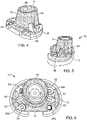
Fig. 1 is an isometric view of a knee prosthesis kit including a tibial tray and an augment. -
Fig. 2 is an isometric view of the tibial tray. -
Figs. 3 and4 are side and isometric views of the augment. -
Fig. 5 is a side view of the tibial tray and augment. -
Fig. 6 is a top view of the tibial tray and augment. -
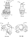
Fig. 7 is a side view of the knee prosthesis kit including a coupler. -
Fig. 8 is a side view of the coupler. -
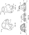
Figs. 9A-16 illustrate additional augments. -
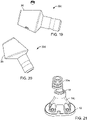
Fig. 17-20 illustrate additional couplers. -
Fig. 21 is an isometric view a knee prosthesis kit including a coupler. -
Fig. 22 illustrates the knee prosthesis kit including a wedge in a total knee replacement. -
Fig. 23 illustrates the knee prosthesis kit including the wedge. -
Fig. 24A is an isometric view of a knee prosthesis kit including a femoral implant and an augment. -
Fig. 24B is an isometric view of the augment ofFig. 24A . -
Fig. 24C is an isometric view of the femoral implant. -
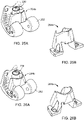
Figs. 25A-27C illustrate additional augments used with femoral implants. - Referring to
Figs. 1-4 , aknee prosthesis kit 10 includes animplant 12 and an augment 14. Theimplant 12, for example, a tibial plate, includes abase 16 and astem 18 extending from thebase 16. The augment 14 has ananterior side 14a and aposterior side 14b, and includes abase 20 and a conical, cylindrical, or anatomic portion, here a cone-shapedportion 22 is shown, extending from thebase 20. To fix the augment 14 to theimplant 12 in a secured, fixed position, the augmentbase 20 includes at least twoopenings 24, here fouropenings 24a-24d are shown, for receiving fasteners 26 (Fig. 6 ) for securing the augment 14 to theimplant base 16. The cone-shapedportion 22 of the augment 14 and the augmentbase 20 define abore 28 sized to receive theimplant stem 18. - The cone-shaped
portion 22 of the augment 14 is designed to optimize fixation of theimplant 12, especially in the case of revision surgeries and/or oncology procedures, to improve fixation of the metaphyseal junction. In revision and primary procedures where the bone quality and ligamentous attachments are compromised, the cone-shapedportion 22 provides additional implant stability by filling the void left by bone deformities thus aiding in ensuring adequate fixation of the implant to the tibia, promoting good function of the implant, and improving the rotational stability of the tibia. - Referring also to
Fig. 5 , theimplant 12 includeswings 50 extending from thestem 18, and the augment 14 hasclearance spaces 52 defined in thebase 20 and the cone-shapedportion 22 that are arranged to receive thewings 50. - Referring to
Figs. 2 and6 , to secure the augment 14 to theimplant 10 usingfasteners 26, theimplant base 16 has at least twoopenings 60, here fouropenings 60a-60d are shown (opening 60b being hidden inFig. 2 ), that align withopenings 24a-24d, respectively, when the augment 14 is positioned on theimplant 12 with theimplant wings 50 received inclearance spaces 52. Theopenings 60a-60d do not extend all the way through the base 16 such that thefasteners 26 located inopenings 24a-24d and 60a-60d do not extend into the joint space and such that any wear debris cannot migrate through the implant to potentially cause osteolysis. - The augment 14 can be used with different
sized implants 12 by varying the distance between opposing cross-openings 24a, 24c and opposing cross-openings 24b, 24d. A smaller spacing betweenopenings smaller implant 12, while a larger spacing betweenopenings larger implant 12. In such a configuration, twofasteners 26 would be placed in opposing openings that align with the implant openings to secure the augment 14 to theimplant 12. Alternatively, the spacing between the pairs of opposing openings can be the same such that the augment 14 has a dedicated size and fourfasteners 26 are used to secure the augment 14 to theimplant 12. The augment 14 can include only two opposingopenings 24 such that a dedicated size augment 14 is attached to the implant using twofasteners 26. - To provide access for insertion of the
fasteners 26 into the augmentopenings portion 22 of the augment 14 hasslots 62 aligned with the augmentbase openings portion 22 can be sintered, stepped, ribbed, or splined to aid in bone purchase. - Referring to
Figs. 7 and 8 , additional components can be attached to theimplant 12 via thestem 18. For example, thekit 10 can further include a standard coupler and/or an offsetcoupler 30 having amating portion 32 for receipt in a bore 34 (Fig. 2 ) of theimplant stem 18. The standard coupler or the offsetcoupler 30 can include in some implementations a cone-shapedportion 36 extending from themating portion 32. The cone-shapedportion 36 defines abore 38 for receipt of amating end 40 of anintramedullary rod 42 of thekit 10. In the offset coupler configuration, thebore 38 has a central axis that is offset from a central axis of themating portion 32, by, for example, 2mm, 4mm, or 6mm. Thekit 10 can include multiple offset couplers with different offsets. - The
mating portion 32 of the coupler and thebore 34 of the implant stem 18 can be tapered such that thecoupler 30 can be secured to theimplant 12 by a taper lock. Likewise, thebore 38 of thecoupler 30 and themating end 40 of theintramedullary rod 42 can be tapered to provide a taper lock therebetween. The cone-shapedportion 36 can define a threaded throughhole 44 extending through the wall of the coupler for receipt of a locking screw. The locking screw extends to a threaded hole 46 (Fig. 2 ) in thestem 18 to aid in securing the coupler to the implant. The outer surface of the coupler can be sintered, stepped, ribbed, or splined to aid in bone purchase. - Referring to
Figs. 9A-12 , alternative augments 14a-14d that generally correspond to augment 14 described above, vary in the curvature of the outer surface of the cone-shapedportion 36. The outer surfaces of the augments 14a-14d have a more rounded contour than augment 14 that extends beyond theopenings posterior slots 70 for receiving fasteners. Due to the more rounded contour, each of the augments 14a-14d also defines aposterior facing notch 72 having a profile which matches the profile of anunderlying implant 12. Each of the augments 14a-14d includes a base and a cone-shaped portion, as described above. The augments can vary in shape and length to accommodate different bone deformities and a variety of tibia base plate implants. - Referring to
Fig. 13 , in an additional implementation, an augment 14e includes abase 20, a cone-shapedportion 22, and acylindrical portion 22a extending from the cone-shapedportion 22. Various views ofaugments implants 12 are shown inFigs. 14-16 , which illustrate how the augments vary in shape to accommodatedifferent implants 12 and different bone deformities. As can be seen inFigs. 14 and15 , the augment 14e is sized relative to theimplant 12 such that when the augment 14e is secured to theimplant base 16, thestem 18 extends out of thebore 28 of the augment. This relative sizing facilitates the attachment of additional components to theimplant 12 via thestem 18. - Referring to
Figs. 17-20 , alternative offsetcouplers 30a-30d generally correspond to offsetcoupler 30 described above, but can includeribs 80 to add in bone purchase, and can include cone-shapedportions 36 of varying shape and/or concave or convex radial features of varying shape to accommodate different bone defects.Fig. 21 illustrates the augment 14e attached to animplant 12 with the offsetcoupler 30a received by thestem 18. - Referring to
Figs. 22 and 23 , thekit 10 can further include one ormore wedges 70 that can be positioned between theimplant 12 and the augment 14 to raise the joint line. Thekit 10 can include the coupler and the one or more wedges. - Rather than a tibial plate, the
implant 12 can be a femoral implant 202 (Figs. 24A and 24B ). Akit 200 for the femoral side includes thefemoral implant 202 and an augment 204. Thefemoral implant 202 has an inner surface in the shape of a box cut having aposterior surface 206, adistal surface 208, and ananterior surface 210 joined todistal surface 208 by anangled surface 212. The augment 204 is sized to be received between the posterior andanterior surfaces - The augment 204 includes a
base 220 and a cone-shapedportion 222. Thebase 220 includes twofeet 224 sized to fit againstdistal surface 208 of theimplant 202 between theposterior surface 206 and theangled surface 212, and within the profile of thedistal surface 208 such that thefeet 224 do not overhang theimplant 202. Theimplant 202 includes astem 230 and the cone-shapedportion 222 of the augment 204 and the augmentbase 220 define abore 232 sized to receive theimplant stem 230. Thebore 232 is large enough to be able to receive thestem 230 of either a right femoral implant or a left femoral implant (Fig. 24A illustrates overlayed right and left femoral implants). - The augment
base 220 has twoopenings 240 for receiving fasteners, and theimplant 202 defines twoopenings 242 aligned withopenings 240 for receiving fasteners (Fig. 24C , only oneopening 242 is shown). Theopenings 242 do not extend all the way through theimplant 202 such that the fasteners do not extend into the joint space. The cone-shapedportion 222 hasslots 244 aligned with the augmentbase openings 242 that provide clearance for the fasteners. - As with the augment 14 discussed above, the cone-shaped
portion 222 of the augment 204 is designed to optimize fixation of theimplant 202, especially in the case of revision surgeries and/or oncology procedures, to improve fixation of the metaphyseal junction. In revision and primary procedures where the bone quality and ligamentous attachments are compromised, the cone-shapedportion 222 provides additional implant stability by filling the void left by bone deformities thus aiding in ensuring adequate fixation of the implant to the femur, promoting good function of the implant, and improving the rotational stability of the femur. - As illustrated in
Figs. 25A-26B ,alternative augments stem 230 of theimplant 202 extends beyond the augment bore 232 to facilitate attachment of further components, for example, a standard and/or offset coupler and anintramedullary rod 252, as discussed above, to thestem 230 of theimplant 202. Thekit 200 can also include one or more wedges, as discussed above. The augments can vary in shape and length to accommodate different bone deformities. - The augment 204 can include a
slit 248 down the side facing theanterior surface 210 of theimplant 202 for receipt by an implant of small size where there is not enough clearance between theanterior surface 210 and thestem 230 for placement of the augment 204 therebetween. The augment 204 can include a locking feature, for example, atail 250 that snaps into theimplant 202 to provide a friction fit between the knee augment 204 and theimplant 202. Additional views of theimplant 202 and augment 204 are shown inFigs. 27A-27C , including theslit 248 and thetail 250. - A kit can include both the tibial components of
kit 10 and the femoral components ofkit 200. - A number of embodiments of the invention have been described. Nevertheless, it will be understood that various modifications may be made without departing from the spirit and scope of the invention. Accordingly, other embodiments are within the scope of the following claims.
- The invention might include, relate to, and/or be defined by the following example aspects:
- 1. A knee prosthesis kit, comprising: an implant including a base and a stem extending from the base; and an augment including a base and a cone-shaped portion extending from the base, the augment base having at least two openings for receiving fasteners for securing the augment to the implant base, the cone-shaped portion and the augment base defining a bore for receipt of the implant post.
- 2. The knee prosthesis kit of aspect 1 wherein the augment is sized relative to the implant such that when the augment is secured to the implant base, the stem extends out of the bore.
- 3. The knee prosthesis kit of aspect 1 wherein the implant includes wings extending from the post, the augment further defining clearance space in at least one of the base and the cone-shaped portion arranged to receive the wings.
- 4. The knee prosthesis kit of aspect 1 wherein the augment base defines four openings for receiving fasteners.
- 5. The knee prosthesis kit of aspect 4 wherein the implant comprises a first implant or a second implant, the first implant being smaller than the second the implant, and wherein a first two of the openings are spaced apart to match the smaller size implant, and the other two of the openings are spaced apart a different amount from the first two openings to match the larger size implant.
- 6. The knee prosthesis kit of aspect 1 wherein the implant base includes at least two openings for receiving fasteners, the implant base openings and the augment base openings being aligned when the augment is fastened to the implant.
- 7. The knee prosthesis kit of aspect 6 wherein the implant base openings do not extend all the way through the implant base.
- 8. The knee prosthesis kit of aspect 1 wherein the augment further comprises a locking feature configured to snap into the implant to provide a friction fit between the augment and the implant.
- 9. The knee prosthesis kit of aspect 1 wherein an outer surface of at least the cone-shaped portion is sintered, stepped, ribbed, or splined.
- 10. The knee prosthesis kit of aspect 1 wherein the augment includes a cylindrical portion extending from the cone-shaped portion.
- 11. The knee prosthesis kit of aspect 1 wherein the cone-shaped portion defines slots aligned with the at least two augment base opening that provide clearance for the fasteners.
- 12. The knee prosthesis kit of aspect 1 further comprising an offset coupler including a mating portion for receipt in a bore of the implant stem and a cone-shaped portion extending from the mating portion, the cone-shaped portion defining a bore for receipt of an intramedullary rod, a central axis of the bore being offset from a central axis of the mating portion.
- 13. The knee prosthesis kit of
aspect 12 wherein the offset coupler is configured to be secured in the bore of the implant stem by a taper lock. - 14. The knee prosthesis kit of
aspect 12 further comprising the intramedullary rod. - 15. The knee prosthesis kit of
aspect 14 wherein the offset coupler bore is configured to secure the intramedullary rod by a taper lock. - 16. The knee prosthesis kit of aspect 1 wherein the implant comprises a tibial plate.
- 17. The knee prosthesis kit of aspect 1 wherein the implant comprises a femoral implant.
- 18. The knee prosthesis kit of aspect 1 further comprising a wedge.
- 19. A knee augment, comprising: a base having at least two openings for receiving fasteners for securing the knee augment to an implant; and a cone-shaped portion extending from the base, the cone-shaped portion and the base defining a bore for receipt of a stem of the implant.
- 20. The knee augment of aspect 19 further defining clearance openings in at least one of the base and the cone-shaped portion arranged to receive wings extending from the stem of the implant.
- 21. The knee augment of aspect 19 wherein the base defines four openings for receiving fasteners.
- 22. The knee augment of aspect 21 wherein a first two of the openings are spaced apart to match a smaller size implant, and the other two of the openings are spaced apart a different amount from the first two openings to match a larger size implant.
- 23. The knee augment of aspect 19 further comprising a locking feature configured to snap into the implant to provide a friction fit between the knee augment and the implant.
- 24. The knee augment of aspect 19 wherein an outer surface of at least the cone-shaped portion is sintered, stepped, ribbed, or splined.
- 25. The knee augment of aspect 19 further comprising a cylindrical portion extending from the cone-shaped portion.
- 26. A coupler, comprising: a mating portion for receipt in a bore of an implant post; and a cone-shaped portion extending from the mating portion, the cone-shaped portion defining a bore for receipt of an intramedullary rod, a central axis of the bore being offset from a central axis of the mating portion.
- 27. The coupler of
aspect 26 wherein an outer surface of the cone-shaped portion is sintered, stepped, ribbed, or splined. - 28. A method of providing fixation of knee implants; comprising: securing an augment to an implant by placing a least two fasteners through openings in the augment and the implant, the augment defining a bore for receipt of a stem of the implant; and positioning a cone-shaped portion of the augment within the intramedullary canal of the tibia or femur.
- 29. The method of
aspect 28 comprising securing the augment to a tibial tray. - 30. The method of
aspect 28 comprising securing the augment to a femoral implant.
Claims (15)
- A knee augment, for use with an implant having a stem, the knee augment comprising:a base having at least one planar portion for contacting the implant; anda cone-shaped portion extending distally from the base in a direction away from the planar surface to a distal end of the cone-shaped portion, the cone-shaped portion having a cone-shaped outer surface, the cone-shaped portion and the base defining a bore for receipt of a stem of the implant;wherein the bore is sized to maintain a space between the stem of the implant and the cone-shaped portion of the augment when the augment is coupled to the implant with the stem received in the bore.
- The knee augment of claim 1, wherein the base includes at least two openings for receiving fasteners for securing the knee augment to the implant, the at least two openings are structured to receive fasteners such that the fasteners extend in a direction transverse to the base.
- The knee augment of claim 2, wherein the cone-shaped portion includes at least two grooves extending from the base in the direction transverse to the base, wherein each groove is aligned with a corresponding one of the at least two openings and provides clearance for a corresponding one of the fasteners.
- The knee augment of any preceding claim, wherein the base and the cone-shaped portion comprise clearance openings arranged to receive fin-like wings extending from the stem of the implant, the clearance openings extending through a portion of the base and the cone-shaped outer surface of the cone-shaped portion.
- The knee augment of claim any preceding claim, further comprising a locking feature configured to snap into the implant to provide a friction fit between the knee augment and the implant.
- The knee augment of any preceding claim, further comprising a cylindrical portion extending from the cone-shaped portion, the cylindrical portion being integrally connected to the cone-shaped portion.
- A knee prosthesis kit, comprising:an implant including an implant base and an implant stem extending from the implant base, the implant base having a superior side and an inferior surface; andthe knee augment according to any preceding claim.
- The knee prosthesis kit of claim 7, wherein the augment including the augment base and the cone-shaped portion is integrally formed.
- The knee prosthesis kit of claim 7 or 8, wherein:
the implant base includes at least two openings for receiving fasteners; and the augment base includes at least two openings, the implant base openings and the augment base openings being aligned so that fasteners can couple the augment to the implant. - The knee prosthesis kit of claim 9, wherein the cone-shaped portion of the augment includes at least two grooves formed therein, wherein the at least two grooves are aligned with the at least two openings to provide clearance for the fasteners.
- The knee prosthesis kit of claim 9 or 10, wherein the implant base openings do not extend all the way through the implant base.
- The knee prosthesis kit of any of claims 9 to 11, wherein the implant comprises a first implant or a second implant, the first implant being smaller than the second implant, and wherein a first two of the openings are spaced apart to match the smaller size implant, and the other two of the openings are spaced apart a different amount from the first two openings to match the larger size implant.
- The knee prosthesis kit of any of claims 7 to 12, further comprising an offset coupler including a mating portion for receipt in a bore of the implant stem and a cone-shaped portion extending from the mating portion, the cone-shaped portion of the offset coupler defining a bore for receipt of an intramedullary rod, a central axis of the bore of the offset coupler being offset from a central axis of the mating portion.
- The knee prosthesis kit of claim 13, wherein the offset coupler is configured to be secured in the bore of the implant stem by a taper lock.
- The knee prosthesis kit of claim 13 or claim 14, further comprising the intramedullary rod, the offset coupler bore is configured to secure the intramedullary rod by a taper lock.
Applications Claiming Priority (3)
| Application Number | Priority Date | Filing Date | Title |
|---|---|---|---|
| US13/833,808 US10596009B2 (en) | 2013-03-15 | 2013-03-15 | Knee augment |
| PCT/US2014/022617 WO2014150218A1 (en) | 2013-03-15 | 2014-03-10 | Knee augment |
| EP14768856.8A EP2967889B1 (en) | 2013-03-15 | 2014-03-10 | Knee augment |
Related Parent Applications (1)
| Application Number | Title | Priority Date | Filing Date |
|---|---|---|---|
| EP14768856.8A Division EP2967889B1 (en) | 2013-03-15 | 2014-03-10 | Knee augment |
Publications (1)
| Publication Number | Publication Date |
|---|---|
| EP4008293A1 true EP4008293A1 (en) | 2022-06-08 |
Family
ID=51531345
Family Applications (2)
| Application Number | Title | Priority Date | Filing Date |
|---|---|---|---|
| EP14768856.8A Active EP2967889B1 (en) | 2013-03-15 | 2014-03-10 | Knee augment |
| EP21211140.5A Withdrawn EP4008293A1 (en) | 2013-03-15 | 2014-03-10 | Knee augment |
Family Applications Before (1)
| Application Number | Title | Priority Date | Filing Date |
|---|---|---|---|
| EP14768856.8A Active EP2967889B1 (en) | 2013-03-15 | 2014-03-10 | Knee augment |
Country Status (3)
| Country | Link |
|---|---|
| US (2) | US10596009B2 (en) |
| EP (2) | EP2967889B1 (en) |
| WO (1) | WO2014150218A1 (en) |
Families Citing this family (35)
| Publication number | Priority date | Publication date | Assignee | Title |
|---|---|---|---|---|
| US9149282B2 (en) | 2011-12-30 | 2015-10-06 | Howmedica Osteonics Corp. | Systems and methods for preparing bone voids to receive a prosthesis |
| US9526513B2 (en) | 2013-03-13 | 2016-12-27 | Howmedica Osteonics Corp. | Void filling joint prosthesis and associated instruments |
| US10596009B2 (en) * | 2013-03-15 | 2020-03-24 | Smith & Nephew, Inc. | Knee augment |
| ES2910362T3 (en) | 2013-03-15 | 2022-05-12 | Canary Medical Inc | Devices, systems and methods for monitoring hip replacements |
| US9445909B2 (en) * | 2013-03-15 | 2016-09-20 | Mako Surgical Corp. | Unicondylar tibial knee implant |
| DK3013283T3 (en) | 2013-06-23 | 2021-03-08 | Canary Medical Inc | Devices, systems and methods for monitoring knee replacements |
| CA3161026A1 (en) | 2014-09-17 | 2016-03-24 | Canary Medical Inc. | Devices, systems and methods for using and monitoring medical devices |
| US10149763B2 (en) | 2015-01-12 | 2018-12-11 | Howmedica Osteonics Corp. | Multipurpose void filling prosthesis |
| GB2534140A (en) * | 2015-01-13 | 2016-07-20 | Imp Innovations Ltd | Joint prosthesis supporting assembly |
| EP3294225B1 (en) * | 2015-05-13 | 2024-10-16 | Smith & Nephew, Inc. | Anatomically relieved augments |
| WO2016183446A1 (en) * | 2015-05-13 | 2016-11-17 | Smith & Nephew, Inc. | Anatomically shaped augments |
| WO2017005513A2 (en) | 2015-07-09 | 2017-01-12 | Waldemar Link Gmbh & Co. Kg | Hollow sleeve augment device and tool |
| IL294630B2 (en) | 2016-03-23 | 2023-12-01 | Canary Medical Inc | An implantable report processor for an alert implant |
| US11191479B2 (en) | 2016-03-23 | 2021-12-07 | Canary Medical Inc. | Implantable reporting processor for an alert implant |
| US10695183B2 (en) * | 2017-03-14 | 2020-06-30 | Charles L. Nelson | Augments and methods of implanting augments |
| US10987225B2 (en) | 2017-08-04 | 2021-04-27 | Zimmer, Inc. | Systems and methods for attaching sleeve or cone in prosthetic implant having a stem |
| WO2019046579A1 (en) * | 2017-08-31 | 2019-03-07 | Smith & Nephew, Inc. | Intraoperative implant augmentation |
| WO2019075066A1 (en) | 2017-10-11 | 2019-04-18 | Zimmer, Inc. | Impaction cradle |
| CN111212616B (en) | 2017-10-13 | 2022-04-12 | 捷迈有限公司 | Revision knee arthroplasty methods and instruments |
| KR101872791B1 (en) * | 2017-11-30 | 2018-06-29 | 주식회사 코렌텍 | Anatomical Shaped Knee Joint Augment |
| AU2019203591B2 (en) | 2018-05-25 | 2024-11-14 | Howmedica Osteonics Corp. | Variable thickness femoral augments |
| CN109145472B (en) * | 2018-08-31 | 2020-06-12 | 西北工业大学 | Weak hinge determining method influencing mechanism motion precision |
| US11083585B2 (en) | 2019-05-09 | 2021-08-10 | Howmedica Osteonics Corp. | Spring retained femoral augment |
| CA3176861A1 (en) | 2019-06-06 | 2020-12-10 | Canary Medical Inc. | Intelligent joint prosthesis |
| US20210366610A1 (en) | 2019-06-06 | 2021-11-25 | Canary Medical Inc. | Intelligent joint prosthesis |
| EP4003238A1 (en) * | 2019-07-24 | 2022-06-01 | Waldemar Link GmbH & Co. KG | Combination of graft and replacement piece for filling a bone defect |
| US11660199B2 (en) * | 2020-01-29 | 2023-05-30 | Encore Medical, L.P. | Modular knee augment cones |
| MX2021014820A (en) | 2020-04-03 | 2022-01-18 | Edwards Lifesciences Corp | MULTILAYER COVER FOR A PROSTHETIC HEART VALVE. |
| IT202000016288A1 (en) * | 2020-07-06 | 2022-01-06 | Limacorporate Spa | AUGMENTATION ELEMENT FOR PROSTHESIS, IN PARTICULAR FOR KNEE PROSTHESIS |
| US12478477B2 (en) | 2021-12-21 | 2025-11-25 | Depuy Ireland Unlimited Company | Modular tibial cone augments and method of surgically using the same |
| US12115084B2 (en) * | 2021-12-21 | 2024-10-15 | Depuy Ireland Unlimited Company | Method of installing a knee cone augment in an orthopaedic surgical procedure |
| US12369930B2 (en) | 2022-06-20 | 2025-07-29 | Zimmer, Inc. | Systems for guided reaming of complex shapes |
| US20240207062A1 (en) | 2022-12-22 | 2024-06-27 | Zimmer, Inc. | Segmented keel for prosthetic implant having a stem |
| DE102023129788A1 (en) * | 2023-10-27 | 2025-04-30 | Aesculap Ag | Augment for a bone implant, set of augments |
| WO2025166405A1 (en) * | 2024-02-08 | 2025-08-14 | Signature Orthopaedics Europe Ltd | Osseointegration augment for orthopaedic implants |
Citations (4)
| Publication number | Priority date | Publication date | Assignee | Title |
|---|---|---|---|---|
| US20070179627A1 (en) * | 2005-12-21 | 2007-08-02 | Gustilo Ramon B | Tibial component with a conversion module for a knee implant |
| US20090149964A1 (en) * | 2007-10-10 | 2009-06-11 | Biomet Manufacturing Corp. | Knee joint prosthesis system and method for implantation |
| US20100298947A1 (en) * | 2009-04-22 | 2010-11-25 | Unger Anthony S | Precision Total Knee Arthroplasty |
| WO2012162180A1 (en) * | 2011-05-20 | 2012-11-29 | Zimmer, Inc. | Stabilizing prosthesis support structure |
Family Cites Families (36)
| Publication number | Priority date | Publication date | Assignee | Title |
|---|---|---|---|---|
| US4790852A (en) * | 1986-09-15 | 1988-12-13 | Joint Medical Products Corporation | Sleeves for affixing artificial joints to bone |
| US4822366A (en) * | 1986-10-16 | 1989-04-18 | Boehringer Mannheim Corporation | Modular knee prosthesis |
| US4888021A (en) * | 1988-02-02 | 1989-12-19 | Joint Medical Products Corporation | Knee and patellar prosthesis |
| US4944757A (en) * | 1988-11-07 | 1990-07-31 | Martinez David M | Modulator knee prosthesis system |
| US5019103A (en) * | 1990-02-05 | 1991-05-28 | Boehringer Mannheim Corporation | Tibial wedge system |
| US5358527A (en) * | 1991-03-22 | 1994-10-25 | Forte Mark R | Total knee prosthesis with resurfacing and posterior stabilization capability |
| US5152797A (en) * | 1991-10-25 | 1992-10-06 | Johnson & Johnson Orthopaedics, Inc. | Modular prosthesis |
| FR2702368B1 (en) * | 1993-03-10 | 1995-06-09 | Medinov Sa | Tibial implant for knee prosthesis. |
| US5489311A (en) * | 1994-01-21 | 1996-02-06 | Joint Medical Products Corporation | Prosthesis with orientable bearing surface |
| US5702464A (en) * | 1996-02-20 | 1997-12-30 | Smith & Nephew Inc. | Modular trial tibial insert |
| US6171342B1 (en) * | 1996-07-23 | 2001-01-09 | Depuy Orthopaedics, Inc. | Medical fastening system |
| US5879391A (en) * | 1996-09-30 | 1999-03-09 | Johnson & Johnson Professional, Inc. | Modular prosthesis |
| US5782920A (en) * | 1996-11-14 | 1998-07-21 | Johnson & Johnson Professional, Inc. | Offset coupling for joint prosthesis |
| US6053945A (en) * | 1997-09-25 | 2000-04-25 | Johnson & Johnson Professional, Inc. | Joint prosthesis having controlled rotation |
| US5951603A (en) * | 1997-09-25 | 1999-09-14 | Johnson & Johnson Professional, Inc. | Rotatable joint prosthesis with axial securement |
| US6162255A (en) * | 1998-10-15 | 2000-12-19 | Depuy Orthopaedics, Inc. | Stem offset mechanism for joint prosthesis |
| US6214052B1 (en) * | 1999-01-19 | 2001-04-10 | Sulzer Orthopedics Inc. | Tibial component with a reversible, adjustable stem |
| US6972039B2 (en) * | 1999-03-01 | 2005-12-06 | Biomet, Inc. | Floating bearing knee joint prosthesis with a fixed tibial post |
| US6953479B2 (en) | 2001-07-16 | 2005-10-11 | Smith & Nephew, Inc. | Orthopedic implant extension |
| US20040162619A1 (en) | 2001-08-27 | 2004-08-19 | Zimmer Technology, Inc. | Tibial augments for use with knee joint prostheses, method of implanting the tibial augment, and associated tools |
| US20030065397A1 (en) * | 2001-08-27 | 2003-04-03 | Hanssen Arlen D. | Prosthetic implant support structure |
| US7892288B2 (en) | 2001-08-27 | 2011-02-22 | Zimmer Technology, Inc. | Femoral augments for use with knee joint prosthesis |
| US6896702B2 (en) * | 2002-05-10 | 2005-05-24 | Howmedica Osteonics Corp. | Securing an augment to a prosthetic implant component |
| US7291174B2 (en) | 2002-09-09 | 2007-11-06 | Depuy Products, Inc. | Prosthetic tibial component with modular sleeve |
| US20040049285A1 (en) * | 2002-09-09 | 2004-03-11 | Brian Haas | Duo-fixation prosthetic joints |
| US6887276B2 (en) * | 2002-12-13 | 2005-05-03 | Medicine Lodge, Inc | Modular implant for joint reconstruction and method of use |
| EP1601316A1 (en) * | 2003-02-04 | 2005-12-07 | Zimmer Austin, Inc. | Rotating/non-rotating tibia plate/insert system |
| US7357817B2 (en) | 2005-05-19 | 2008-04-15 | Howmedica Osteonics Corp. | Modular keel tibial component |
| US7842093B2 (en) * | 2006-07-18 | 2010-11-30 | Biomet Manufacturing Corp. | Method and apparatus for a knee implant |
| US7740662B2 (en) * | 2006-10-13 | 2010-06-22 | Depuy Products, Inc. | Mobile/fixed prosthetic knee systems |
| US8163028B2 (en) * | 2007-01-10 | 2012-04-24 | Biomet Manufacturing Corp. | Knee joint prosthesis system and method for implantation |
| EP2394608A1 (en) | 2008-06-03 | 2011-12-14 | DePuy Products, Inc. | Porous titanium femoral sleeves |
| US9855147B2 (en) * | 2011-02-15 | 2018-01-02 | Omni Life Science Inc. | Modular prosthesis |
| US8979847B2 (en) * | 2011-06-06 | 2015-03-17 | Biomet Manufacturing, Llc | Method and apparatus for implanting a knee prosthesis |
| US8968413B2 (en) * | 2013-03-14 | 2015-03-03 | Depuy (Ireland) | Orthopaedic tibial prosthesis having tibial augments |
| US10596009B2 (en) * | 2013-03-15 | 2020-03-24 | Smith & Nephew, Inc. | Knee augment |
-
2013
- 2013-03-15 US US13/833,808 patent/US10596009B2/en active Active
-
2014
- 2014-03-10 WO PCT/US2014/022617 patent/WO2014150218A1/en not_active Ceased
- 2014-03-10 EP EP14768856.8A patent/EP2967889B1/en active Active
- 2014-03-10 EP EP21211140.5A patent/EP4008293A1/en not_active Withdrawn
-
2020
- 2020-02-07 US US16/784,680 patent/US11707358B2/en active Active
Patent Citations (4)
| Publication number | Priority date | Publication date | Assignee | Title |
|---|---|---|---|---|
| US20070179627A1 (en) * | 2005-12-21 | 2007-08-02 | Gustilo Ramon B | Tibial component with a conversion module for a knee implant |
| US20090149964A1 (en) * | 2007-10-10 | 2009-06-11 | Biomet Manufacturing Corp. | Knee joint prosthesis system and method for implantation |
| US20100298947A1 (en) * | 2009-04-22 | 2010-11-25 | Unger Anthony S | Precision Total Knee Arthroplasty |
| WO2012162180A1 (en) * | 2011-05-20 | 2012-11-29 | Zimmer, Inc. | Stabilizing prosthesis support structure |
Also Published As
| Publication number | Publication date |
|---|---|
| US20200170803A1 (en) | 2020-06-04 |
| US20140277528A1 (en) | 2014-09-18 |
| EP2967889A4 (en) | 2017-04-19 |
| US11707358B2 (en) | 2023-07-25 |
| US10596009B2 (en) | 2020-03-24 |
| EP2967889A1 (en) | 2016-01-20 |
| EP2967889B1 (en) | 2021-12-01 |
| WO2014150218A1 (en) | 2014-09-25 |
Similar Documents
| Publication | Publication Date | Title |
|---|---|---|
| US11707358B2 (en) | Knee augment | |
| US12274455B2 (en) | Void filling joint prosthesis and associated instruments | |
| US11877757B2 (en) | Systems and methods for preparing bone voids to receive a prosthesis | |
| EP2181673B1 (en) | Knee prosthesis kit with a winged metaphyseal sleeve | |
| US9820858B2 (en) | Knee implants and instruments | |
| EP4048159B1 (en) | Orthopedic implant system with augmentation device | |
| US7112203B2 (en) | Apparatus for the preparation of a femur bone for the implantation of a prosthesis | |
| AU2019250233B2 (en) | Tibial implant having an anatomic stem | |
| EP2664301A1 (en) | Prosthesis kit with finned sleeve | |
| US20070260321A1 (en) | Conically-shaped glenoid implant with a prosthetic glenoid insert used in total shoulder arthroplasty and method | |
| US20160228254A1 (en) | Implant Set Having Modularity with Conformity for Total Knee Replacement | |
| KR102413389B1 (en) | Modular Augment |
Legal Events
| Date | Code | Title | Description |
|---|---|---|---|
| PUAI | Public reference made under article 153(3) epc to a published international application that has entered the european phase |
Free format text: ORIGINAL CODE: 0009012 |
|
| STAA | Information on the status of an ep patent application or granted ep patent |
Free format text: STATUS: THE APPLICATION HAS BEEN PUBLISHED |
|
| AC | Divisional application: reference to earlier application |
Ref document number: 2967889 Country of ref document: EP Kind code of ref document: P |
|
| AK | Designated contracting states |
Kind code of ref document: A1 Designated state(s): AL AT BE BG CH CY CZ DE DK EE ES FI FR GB GR HR HU IE IS IT LI LT LU LV MC MK MT NL NO PL PT RO RS SE SI SK SM TR |
|
| STAA | Information on the status of an ep patent application or granted ep patent |
Free format text: STATUS: REQUEST FOR EXAMINATION WAS MADE |
|
| 17P | Request for examination filed |
Effective date: 20220915 |
|
| RBV | Designated contracting states (corrected) |
Designated state(s): AL AT BE BG CH CY CZ DE DK EE ES FI FR GB GR HR HU IE IS IT LI LT LU LV MC MK MT NL NO PL PT RO RS SE SI SK SM TR |
|
| STAA | Information on the status of an ep patent application or granted ep patent |
Free format text: STATUS: EXAMINATION IS IN PROGRESS |
|
| 17Q | First examination report despatched |
Effective date: 20230424 |
|
| STAA | Information on the status of an ep patent application or granted ep patent |
Free format text: STATUS: THE APPLICATION IS DEEMED TO BE WITHDRAWN |
|
| 18D | Application deemed to be withdrawn |
Effective date: 20251001 |