EP4008202A1 - Cartomiseur avec éléments de fixation pour un dispositif de génération d'aérosol - Google Patents
Cartomiseur avec éléments de fixation pour un dispositif de génération d'aérosol Download PDFInfo
- Publication number
- EP4008202A1 EP4008202A1 EP20210937.7A EP20210937A EP4008202A1 EP 4008202 A1 EP4008202 A1 EP 4008202A1 EP 20210937 A EP20210937 A EP 20210937A EP 4008202 A1 EP4008202 A1 EP 4008202A1
- Authority
- EP
- European Patent Office
- Prior art keywords
- aerosol
- cartomizer
- bayonet mount
- open position
- fluid path
- Prior art date
- Legal status (The legal status is an assumption and is not a legal conclusion. Google has not performed a legal analysis and makes no representation as to the accuracy of the status listed.)
- Withdrawn
Links
Images

Classifications
-
- A—HUMAN NECESSITIES
- A24—TOBACCO; CIGARS; CIGARETTES; SIMULATED SMOKING DEVICES; SMOKERS' REQUISITES
- A24F—SMOKERS' REQUISITES; MATCH BOXES; SIMULATED SMOKING DEVICES
- A24F40/00—Electrically operated smoking devices; Component parts thereof; Manufacture thereof; Maintenance or testing thereof; Charging means specially adapted therefor
- A24F40/40—Constructional details, e.g. connection of cartridges and battery parts
- A24F40/49—Child proofing
-
- A—HUMAN NECESSITIES
- A24—TOBACCO; CIGARS; CIGARETTES; SIMULATED SMOKING DEVICES; SMOKERS' REQUISITES
- A24F—SMOKERS' REQUISITES; MATCH BOXES; SIMULATED SMOKING DEVICES
- A24F40/00—Electrically operated smoking devices; Component parts thereof; Manufacture thereof; Maintenance or testing thereof; Charging means specially adapted therefor
- A24F40/40—Constructional details, e.g. connection of cartridges and battery parts
- A24F40/42—Cartridges or containers for inhalable precursors
-
- A—HUMAN NECESSITIES
- A24—TOBACCO; CIGARS; CIGARETTES; SIMULATED SMOKING DEVICES; SMOKERS' REQUISITES
- A24F—SMOKERS' REQUISITES; MATCH BOXES; SIMULATED SMOKING DEVICES
- A24F40/00—Electrically operated smoking devices; Component parts thereof; Manufacture thereof; Maintenance or testing thereof; Charging means specially adapted therefor
- A24F40/40—Constructional details, e.g. connection of cartridges and battery parts
- A24F40/48—Fluid transfer means, e.g. pumps
- A24F40/485—Valves; Apertures
-
- A—HUMAN NECESSITIES
- A24—TOBACCO; CIGARS; CIGARETTES; SIMULATED SMOKING DEVICES; SMOKERS' REQUISITES
- A24F—SMOKERS' REQUISITES; MATCH BOXES; SIMULATED SMOKING DEVICES
- A24F40/00—Electrically operated smoking devices; Component parts thereof; Manufacture thereof; Maintenance or testing thereof; Charging means specially adapted therefor
- A24F40/10—Devices using liquid inhalable precursors
Definitions
- the present invention relates to an aerosol generation device, and more precisely to a cartomizer intended for equipping an aerosol generation device.
- Some aerosol generation devices comprise a control device comprising a power source, possibly a rechargeable battery, and a cartomizer mechanically and electrically coupled to this electrical and control device.
- the cartomizer is a consumable formed as an exchangeable assembly of a cartridge (or capsule) and an atomizing device.
- the cartridge comprises at least one reservoir containing an aerosol-forming precursor.
- the atomizing device is arranged for heating aerosol-forming precursor to generate an aerosol in a heating (or atomization) chamber fluidly coupled to a mouthpiece (or mouth end).
- a heating (or atomization) chamber fluidly coupled to a mouthpiece (or mouth end).
- aerosol may include a suspension of precursor as one or more of solid particles, liquid droplets and gas. Such a suspension may be in a gas including air. Aerosol herein may generally refer to, or include, a vapor, and may include one or more components of the precursor.
- the term "aerosol-forming precursor” may refer to a fluid.
- the precursor may be processable by the heating device of the cartomizer to form an aerosol, and may comprise components such as one or more nicotinoids, one or more cannabinoids, or caffeine.
- a component may be carried by a carrier, which may be an aerosolisable liquid comprising aerosol former such as propylene glycol, glycerol for instance, water and oil such as terpene.
- a flavoring may also be present in the aerosol-forming precursor. The flavoring may include Ethylvanillin (vanilla), menthol, Isoamyl acetate (banana oil) or similar, for instance.
- the heating of the aerosol-forming precursor is carried out by conduction, convection and/or radiation by a heating device of the atomization device, which is possibly housed inside the heating chamber.
- a heating device may comprise one or more electrically activated resistive and/or inductive heating elements.
- the aerosol generation device may be portable, i.e. usable when held by a user, and adapted to generate a variable amount of aerosol, e.g. by activating the heating device partially or totally possibly for a variable amount of time (as opposed to a metered dose of aerosol).
- the variable amount of aerosol can be controlled by a controller and an inhalation sensor and possibly by user's input(s) on a user interface.
- the inhalation sensor may be sensitive to the strength of inhalation as well as the duration of inhalation to enable a variable amount of vapor to be provided (so as to mimic the effect of smoking a conventional combustible smoking article such as a cigarette, cigar or pipe).
- the inhalation sensor is a flow or pressure sensor or microphone positioned in the air flow path in the aerosol generation device.
- the aerosol generation device includes also a temperature regulation control to drive the temperature of the heating device and/or the heated aerosol-forming precursor to a specified target temperature and thereafter to maintain the temperature at the target temperature that enables an efficient generation of aerosol.
- the invention concerns the cartomizers comprising :
- the user couples first the first part to the second part to constitute a cartomizer and then mechanically and electrically couples the cartomizer to the corresponding electrical and control device to constitute an aerosol generation device.
- the cartomizer is ready to use, i.e. in its open position, and therefore when he couples this cartomizer to the electrical and control device a vaping session can start after switching the aerosol generation device on.
- the user has two possibilities : either he switches the aerosol generation device off and leaves it in the open position, or he must rotate manually the second part relative to the first part to cause a transition from the open position to the closed position.
- the cartomizer remains in its open position and therefore some aerosol-forming precursor may leak out of it at both ends (mouth end and air inlet end), notably when the aerosol generation device is carried (with no guarantee that it will remain in an upright position). Therefore, if the user wants to avoid a leakage when he carries the aerosol generation device, he must continuously maintain the cartomizer in upright position, which is not an easy task.
- the second part of the cartomizer is no longer coupled to the associated first part (which remains coupled to the electrical and control device). So, when the user wants to start a new vaping session he must couple again the second part to the first part (coupled to the electrical and control device), which can take time, notably when the second part and the first part with the electrical and control device have been stored in different locations.
- such a solution requires to provide with sealing means not only the first part but also the second part to avoid leakages of aerosol-forming precursor, which renders more complex the first and second parts of the cartomizer.
- This cartomizer is characterized in that its first part and its second part comprise respectively complementary first and second fastening elements arranged for holding the second part attached to the first part either in the closed position when they are set together in a first relative position, or in the open position when they are set together in a second relative position.
- the invention in both closed and open positions the first and second parts are attached together, which notably avoids the user having to decouple the second part from the first part when he does not want temporarily to use the aerosol generation device and to couple the second part to the first part when he wants to use the aerosol generation device.
- cartomizer may comprise other aspects or features, considered separately or combined, as defined hereafter.
- the proposed invention provides also an embodiment of an aerosol generation device comprising an electrical and control device and a cartomizer such as the one above introduced and mechanically and electrically coupled to this electrical and control device.
- the embodiment of aerosol generation device may comprise other features, considered separately or combined, as defined hereafter.
- the invention aims, notably, at offering a cartomizer 1 intended for being mechanically and electrically coupled to an electrical and control device 2 to define together an aerosol generation device 3.
- the aerosol generation device 3 is an electronic cigarette (or e-cigarette or else personal vaporizer). But an aerosol generation device according to the invention could be of another type, as soon as it comprises a cartomizer 1 according to the invention and allows the generation of an aerosol by heating an aerosol-forming precursor. So, for instance, the aerosol generation device 3 could be an inhaler.
- an "aerosol-forming precursor” may be a fluid (for instance a liquid), and may comprise one or more components such as nicotinoid(s), cannabinoid(s), or caffeine, and/or a flavoring.
- anosol may include a suspension of precursor as one or more of solid (very small) particles, liquid droplets, vapor and gas, and that such a suspension may be in a gas including air.
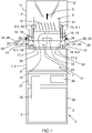
- a cartomizer 1 As illustrated in figures 1 and 2 a cartomizer 1, according to the invention and intended for equipping an aerosol generation device 3, comprises a first part 4, a second part 5, and at least one fluid path 6-j.
- the first part 4 comprises a reservoir 7 arranged for storing an aerosol-forming precursor.
- the first part 4 comprises only one reservoir 7. But it could comprise several (for instance two, three or four) reservoirs storing identical or different aerosol-forming precursors. It could be possible to have two different aerosol-forming precursors to either have them react with each other in a heating chamber 8 (for instance one with nicotine salts and the other one with an acid source (e.g. a benzoic acid)) or to allow the user to choose between different flavours (first flavour, second flavor, or a mixture of both (possibly the user being able to determine the amount of each of them)).
- a heating chamber 8 for instance one with nicotine salts and the other one with an acid source (e.g. a benzoic acid)
- an acid source e.g. a benzoic acid
- the (each) reservoir 7 is defined in a first housing 9 of the first part 4.
- the (each) reservoir 7 may be integral with, or inserted in, the first housing 9.
- the coupling between the cartomizer 1 (and more precisely the first housing 9) and the electrical and control device 2 can be done by screwing by means of two corresponding threaded portions, or by clipping.
- the first housing 9 (of the first part 4) may comprise a first threaded portion arranged for being screwed relatively to a corresponding second threaded portion of a third housing 34 of the electrical and control device 2.
- the electrical and control device 2 could comprise a cavity for receiving a part of the cartomizer 1. In this case, this cavity may comprise magnets interacting with magnets of the cartomizer 1.
- the second part 5 comprises a heating (or atomization) chamber 8 configured, when it is fed with air and aerosol-forming precursor, for heating the latter to generate an aerosol.
- This second part 5 is movable relative to the first part 4 between a relative closed position illustrated in figure 1 and a relative open position illustrated in figure 2 .
- the first part 4 may comprise a deep guiding hole and the second part may comprise an axis or axle housed into this guiding hole when the first 4 and second 5 parts are coupled together, for instance.
- the heating (or atomization) chamber 8 is configured, when it is fed with air and aerosol-forming precursor, for heating the latter to generate an aerosol.
- the heating chamber 8 may be fluidly coupled to a mouthpiece (or mouth end) 10, possibly via an aerosol passage (not illustrated).
- the mouthpiece 10 is the piece of the cartomizer 1 through which the user inhales the aerosol generated in the heating chamber 8 (and possibly flowing into an aerosol passage) during a vaping session (as illustrated by the arrow C in figure 2 ).
- the heating chamber 8 may be defined in a second housing 11 of the second part 5. This heating chamber 8 may be integral with, or inserted in, the second housing 11.
- the second housing 11 comprises an end to which the mouthpiece 10 is fixed, for instance by screwing or clipping. But the mouthpiece 10 could also be glued or moulded integrally with the second housing 11.
- the heating chamber 8 comprises an electrical heating device 12 arranged for heating the aerosol-forming precursor to generate the aerosol (originating from a (the) reservoir 7), when it receives electrical energy originating from a power source 13 of the electrical and control device 2.
- This heating device 12 and the heating chamber 8 belongs to the atomization device of the cartomizer 1.
- the heating device 12 may be a resistive heater, such as a resistive coil, and/or an inductive heater, such as a metallic susceptor.
- the heating device 12 may comprise one or more electrically activated resistive and/or inductive heating elements. But in a variant (not illustrated) the heating device 12 could be partly outside the heating chamber 8.
- the heating can be made by conduction, convection and/or radiation.
- the first part 4 and the electrical and control device 2 may comprise respectively electrical pins intended for contacting each other during their coupling.
- the second part 5 comprises at least one air passage 14 configured for feeding its heating chamber 8 with air sucked in by the user.
- this (each) air passage 14 may be connected to an air inlet 24 of the first part 4 when the cartomizer 1 is in its open position.
- This air inlet 24 is in communication with the outside (as illustrated by the arrow A in figure 2 ).
- the (each) air passage 14 may be integral with, or inserted in, the second housing 11. When it is inserted, it may be a conduit or pipe. In a variant the air inlet could be defined in the first part 4 and connected to a conduit of the second part 5.
- the (each) fluid path 6-j is defined between the (a) reservoir 7 and the heating chamber 8 and comprises an outlet 15 in the first part and an inlet 16 located in the second part 5.
- the outlet 15 (of each fluid path 6-j) is facing the inlet 16 (of the same fluid path 6-j) in the open position to allow the aerosol-forming precursor to leave the corresponding reservoir 7 to reach the heating chamber 8.
- the outlet 15 (of each fluid path 6-j) is offset from the inlet (of the same fluid path 6-j) in the closed position to prevent the aerosol-forming precursor to reach the heating chamber 8.
- first part 4 and the second part 5 comprise respectively complementary first 25 and second 26 fastening elements arranged for holding the second part 5 attached to the first part 4 either in the closed position when they are set together in a first relative position, or in the open position when they are set together in a second relative position.
- the second fastening element 26 may comprise two bayonet mount legs
- the first fastening element 25 may comprise two first female bayonet mount members 27 and two second female bayonet mount members 28.
- the two first female bayonet mount members 27 are arranged for receiving and holding respectively the two bayonet mount legs 26 in the open position (and therefore in the first relative position of the first 25 and second 26 fastening elements).
- the two second female bayonet mount members 28 are arranged for receiving and holding respectively the two bayonet mount legs 26 in the closed position (and therefore in the second relative position of the first 25 and second 26 fastening elements).
- the first fastening element 25 may comprise two bayonet mount legs
- the second fastening element 26 may comprise two first female bayonet mount members and two second female bayonet mount members.
- the two first female bayonet mount members are arranged for receiving and holding respectively the two bayonet mount legs 26 in the open position (and therefore in the first relative position of the first 25 and second 26 fastening elements).
- the two second female bayonet mount members are arranged for receiving and holding respectively the two bayonet mount legs 26 in the closed position (and therefore in the second relative position of the first 25 and second 26 fastening elements).
- the first bayonet mount members 27 may be distant from corresponding second bayonet mount members 28 along a direction parallel to an axis of rotation 23 of the second part 5 in order that the first part 4 is spaced from the second part 5 in the closed position.
- the two first bayonet mount members 27 are defined at a first vertical level while the two second bayonet mount members 28 are defined at a second vertical level, higher than the first vertical level.
- the transition between the relative closed and open positions requires a combination of axial translation(s) (parallel to the axis of rotation 23) and rotation(s) (around the axis of rotation 23) for leaving the first bayonet mount members 27 and reaching the axially distant second bayonet mount members 28, and vice versa.
- first 27 and second 28 bayonet mount members could be defined at a same level.
- each first bayonet mount member 27 is separated from the corresponding second bayonet mount member 28 by a chosen angular sector (possibly, but not limitatively, equal to 90°).
- the transition between the relative closed and open positions requires a combination of small axial translations (parallel to the axis of rotation 23) and rotations (around the axis of rotation 23) for leaving the first bayonet mount members 27 and reaching the angularly distant second bayonet mount members 28, and vice versa.
- the first 27 and second 28 bayonet mount members may be recesses. As illustrated, these recesses 27 and 28 may be joined by a helical recess path defined in a protruding wall 29 of the first housing 9 and allowing the bayonet mount legs 26 to travel between the open and closed positions.
- the air inlet 24 may be defined in this protruding wall 29 of the first part 4, as illustrated.
- each arm comprises a first bayonet mount member 27 and a second bayonet mount member 28 distant from this first bayonet mount member 27.
- the air inlet 24 may be defined in one of the arms of the first part 4.
- the cartomizer 1 may comprise at least one valve 17-j arranged in the (a) fluid path 6-j and configured to be opened in the cartomizer open position (illustrated in figure 2 ) and closed in the cartomizer closed position (illustrated in figure 1 ).
- valve 17-j associated with each fluid path 6-j it is possible to prevent the aerosol-forming precursor to leave the (its) reservoir 7 when the cartomizer 1 is set in its closed position (in which the fluid path outlet 15 is offset from the corresponding fluid path inlet 16).
- the valve 17-j in its closed position and therefore the aerosol-forming precursor is prevented from leaving the reservoir 7 and then cannot reach the free space 32 separating the first 9 and second 11 housings in the illustrated example of embodiment.
- the valve 17-j in its open position and therefore the aerosol-forming precursor can leave the reservoir 7 to reach the heating chamber 8 via the corresponding fluid path 6-j (see arrows B). So, when the cartomizer 1 is in its closed position it cannot leak, even when it is not in its upright position.
- valves 17-j allow also to simplify the first 4 and second 5 parts because the number of sealing means is divided by two compared to the proposed solutions of the art.
- each valve 17-j may be advantageously arranged in the outlet 15 of its fluid path 6-j.
- the inlet 16 of each fluid path 6-j could also comprise another valve to avoid fluid from dripping from the fluid path inlet 16 back to the reservoir surface.
- each valve 17-j may comprise a resealable wall which is configured to open when it is subject to a constraint in the cartomizer open position and to automatically close when this constraint disappears in the closed position.
- each resealable wall is a kind of "nib" working in the same way as a valve action marker.
- a nib When such a nib is pressed aerosol-forming precursor flows in its free end, and when it is not pressed (i.e. not subject to a constraint) the aerosol-forming precursor cannot flow to this free end and therefore the valve 17-j is closed to prevent leakage.
- each fluid path 6-j may comprise an opening element 18 arranged for constraining this resealable wall in the open position to force the opening of the corresponding valve 17-j. So, during a manual transition of the cartomizer 1 from its closed position to its open position (operated by a user), the opening element 18 exerts a constraint on the corresponding resealable wall which finally forces the opening of the latter and therefore of the corresponding valve 17-j.
- the opening element 18 is positioned in the fluid path inlet 16 in a manner that allows to engage and open this valve 17-j when the fluid path outlet 15 and fluid path inlet 16 are facing each other.
- the opening element 18 may be a tube portion, a pin, a needle, a probe and the like.
- each fluid path 6-j may comprise first 19 and second 20 sub-parts.
- the first sub-part 19 of each fluid path 6-j comprises the outlet 15 and protrudes from the first part 4 to be housed in the second part 5 at least in the open position.
- each first sub-part 19 protrudes from the first part 4 to be housed in the second part 5 only in the open position because the first 27 and second 28 bayonet mount members are defined at different levels. But in the case where the first 27 and second 28 bayonet mount members are defined at a same level, each first sub-part 19 protrudes from the first part 4 to be housed in the second part 5 both in the open and closed positions.
- the second sub-part 20 is defined in the second part 5 and comprises the inlet 16.
- the first 19 and second 20 sub-parts of each fluid path 6-j are positioned adjacent to each other in the open position, and are spatially separated in the closed position, as illustrated in figure 2 .
- the first 19 and second 20 sub-parts of each fluid path 6-j are axially separated along the direction parallel to the axis of rotation 23 in the closed position.
- the first 19 and second 20 sub-parts of each fluid path 6-j are separated by a predefined angular sector in the closed position.
- Each first sub-part 19 is preferably an inserted rigid pipe (or conduit) having an inlet coupled to the reservoir 7 and an outlet which is the outlet 15 of its fluid path 6-j.
- Each second sub-part 20 is also preferably an inserted rigid pipe (or a conduit possibly formed by plastic moulding) having an inlet which is the inlet 16 of its fluid path 6-j and an outlet coupled to the heating chamber 8.
- the second housing 11 may comprise two recesses 30 housing permanently and respectively the two second sub-parts 20, and partially the two first sub-parts 19 (and notably their outlets 15, and possibly the associated valve 17-j) at least in the cartomizer open position.
- each first sub-part 19 may, for instance, comprise an end defining this outlet 15, comprising the valve 17-j and opposite to the reservoir 7.
- each opening element 18 may be an end of the second sub-part 20 which comprises the inlet 16 and opposite to the heating chamber 8.
- each second sub-part 20 may comprise an end defining its inlet 16, comprising the valve 17-j and opposite to the heating chamber 8. More, each opening element 18 may be an end of a first sub-part 19 which comprises the outlet 15 of its fluid path 6-j and opposite to the reservoir 7.
- This arrangement allows to improve the feeding of the heating chamber 8 with the aerosol-forming precursor, or to feed the heating chamber 8 with two different aerosol-forming precursors originating respectively from two different reservoirs 7.
- the second part 5 may be rotatably mounted on an external face of the first housing 9 of the first part 4 in order to be an extension of this first part 4.
- the electrical and control device 2 and the first 4 and second 5 parts of the cartomizer 1 are aligned with the first part 4 sandwiched between the electrical and control device 2 and the second part 5.
- first 6-1 and second 6-2 fluid paths their first sub-parts 19 and the axis of rotation 23 of the second part 5 may be located in a same plane, as illustrated in the non-limiting example of figures 1 and 2 .
- each manual transition between the closed and open positions requires a combination of axial translation(s) (parallel to the axis of rotation 23) and rotations (around the axis of rotation 23).
- the recesses 27 and 28 are joined by a helical recess path, as illustrated, one of these rotations is a relative rotation of the second part 5 with respect to the first part 4. In the illustrated example this relative rotation is equal to 180°. But this relative rotation may be a complete turn (360°) or any other possible angular sector.
- the heating chamber 8 may comprise an aerosol-forming precursor collecting element 31 to collect aerosol-forming precursor flowing into each fluid path 6-j (in the cartomizer open position), and the heating device 12 in contact with this aerosol-forming precursor collecting element 31.
- the outlets of the two sub-parts 20 of the first 6-1 and second 6-2 fluid paths are coupled respectively to the two opposite ends of the aerosol-forming precursor collecting element 31.
- this aerosol-forming precursor collecting element 31 may be a capillary element (possibly a capillary wick).
- This capillary element 31 can be a fiber or ceramic rod, for instance.
- the heating device 12 may comprise a resistive coil wound around the capillary element 31 and coupled to the above mentioned pins via lead wires.
- the cartomizer 1 may comprise a pulling force element 33 configured to provide an attraction force between the first 4 and second 5 parts.
- a pulling force element 33 configured to provide an attraction force between the first 4 and second 5 parts.
- This allows the second part 5 to remain precisely in a fixed position with respect to the first part 4 when the cartomizer 1 is in its open and closed positions.
- an attraction element can facilitate the return to the open position.
- the attraction element can be made by one or more springs (e.g. torsion spring) and/or magnets.
- the pulling force element 33 may be a spring-type device or a magnetic device.
- the spring-type device or the magnetic device is preferably inserted between the first 4 and second 5 parts to provide attraction force in the open and/or closed positions.
- the cartomizer 1 comprises a pulling force element 33
- the user must pull apart the first 4 and second 5 parts first before starting a transition between the closed and open positions. This allows to prevent accidental rotation and activation of the cartomizer 1 with the added benefit of preventing use by a child, especially in the case where an attraction element works to maintain the first 4 and second 5 parts distant and make it hard to put them in open position.
- the third housing 34 of the electrical and control device 2 may comprise at least a controller (or control device) 35 and a user interface 36 in addition to the power source 13 (storing electrical energy).
- the power source 13 may be a rechargeable battery.
- the third housing 34 may comprise an electrical connector to which a charger cable may be connected during a charging session of the rechargeable battery 13.
- a charger cable may be coupled to an (AC) adapter or to a wall socket.
- the charger cable and/or the (AC) adapter may belong to the aerosol generation device 3.
- the controller 35 is electrically coupled to the power source 13 and controls operation of the cartomizer 1 (and notably its heating device 12) during a vaping session and also during a possible charging session.
- the controller 35 may be fixed onto a printed circuit board 37 (housed in the third housing 34).
- controller should not be construed to refer exclusively to hardware capable of executing software, and may implicitly include, without limitation, digital signal processor (DSP) hardware, processor, application specific integrated circuit (ASIC), field programmable gate array (FPGA), read only memory (ROM) for storing software, random access memory (RAM), and non volatile storage. Other hardware, conventional and/or custom, may also be included.
- DSP digital signal processor
- ASIC application specific integrated circuit
- FPGA field programmable gate array
- ROM read only memory
- RAM random access memory
- non volatile storage Other hardware, conventional and/or custom, may also be included.
- the functions of the controller 35 may be carried out through the operation of program logic, through dedicated logic, through the interaction of program control and dedicated logic, or even manually (by the user). These functions may be provided through the use of dedicated hardware as well as hardware capable of executing software in association with appropriate software.
- the user interface 36 is coupled to the controller 35 and the power source 13 and allows the user to control at least partly the controller 35.
- the user interface 36 may comprise a display (such as a screen or light emitting diode (or LED)-type interface) arranged for displaying information relative to a current vaping session or a possible current charging session and for allowing the user to control the controller 35.
- the displayed information may be a current status representing the current percentage of remaining (or elapsed) vaping time (with respect to a programmed (or chosen) vaping duration) during a vaping session, or the current percentage of charge (with respect to the full charge) of the power source 13 during a possible charging session.
- the current percentage may be represented by the length of a straight line or by a number of parallel bars or else by a value, for instance.
- the user interface 36 may be fixed partly to the printed circuit board 37 to ease and simplify its connections with the controller 35.
- the user interface 36 may have its own printed circuit board connected to the printed circuit board 37 by wires of flexible circuit(s) in order to be deported anywhere.
- the second part 5 may comprise a puff sensor (not illustrated) intended for detecting when the user sucks in (or inhales) during a vaping session, and for informing the controller 35 each time such a detection occurs.
- the puff sensor can be a flow or pressure sensor or microphone positioned in the air flow path. For instance, if the air inlet is defined in the first part 4 the puff sensor can be placed in this first part 4.
Priority Applications (1)
| Application Number | Priority Date | Filing Date | Title |
|---|---|---|---|
| EP20210937.7A EP4008202A1 (fr) | 2020-12-01 | 2020-12-01 | Cartomiseur avec éléments de fixation pour un dispositif de génération d'aérosol |
Applications Claiming Priority (1)
| Application Number | Priority Date | Filing Date | Title |
|---|---|---|---|
| EP20210937.7A EP4008202A1 (fr) | 2020-12-01 | 2020-12-01 | Cartomiseur avec éléments de fixation pour un dispositif de génération d'aérosol |
Publications (1)
| Publication Number | Publication Date |
|---|---|
| EP4008202A1 true EP4008202A1 (fr) | 2022-06-08 |
Family
ID=73654690
Family Applications (1)
| Application Number | Title | Priority Date | Filing Date |
|---|---|---|---|
| EP20210937.7A Withdrawn EP4008202A1 (fr) | 2020-12-01 | 2020-12-01 | Cartomiseur avec éléments de fixation pour un dispositif de génération d'aérosol |
Country Status (1)
| Country | Link |
|---|---|
| EP (1) | EP4008202A1 (fr) |
Citations (5)
| Publication number | Priority date | Publication date | Assignee | Title |
|---|---|---|---|---|
| US9861136B2 (en) | 2015-02-04 | 2018-01-09 | Shenzhen First Union Technology Co., Ltd. | Liquid supply, atomizer and electronic cigarette having same |
| EP3366150A2 (fr) * | 2017-06-19 | 2018-08-29 | Shenzhen First Union Technology Co., Ltd. | Ensemble d'atomisation |
| WO2018177826A1 (fr) * | 2017-03-29 | 2018-10-04 | Jt International S.A. | Appareil, système et procédé de génération d'aérosol |
| WO2019115113A1 (fr) * | 2017-12-12 | 2019-06-20 | Jt International Sa | Système d'alimentation en fluide pour cigarette électronique |
| EP3566596A2 (fr) * | 2018-07-23 | 2019-11-13 | Shenzhen First Union Technology Co., Ltd. | Article de génération d'aérosol détachable |
-
2020
- 2020-12-01 EP EP20210937.7A patent/EP4008202A1/fr not_active Withdrawn
Patent Citations (5)
| Publication number | Priority date | Publication date | Assignee | Title |
|---|---|---|---|---|
| US9861136B2 (en) | 2015-02-04 | 2018-01-09 | Shenzhen First Union Technology Co., Ltd. | Liquid supply, atomizer and electronic cigarette having same |
| WO2018177826A1 (fr) * | 2017-03-29 | 2018-10-04 | Jt International S.A. | Appareil, système et procédé de génération d'aérosol |
| EP3366150A2 (fr) * | 2017-06-19 | 2018-08-29 | Shenzhen First Union Technology Co., Ltd. | Ensemble d'atomisation |
| WO2019115113A1 (fr) * | 2017-12-12 | 2019-06-20 | Jt International Sa | Système d'alimentation en fluide pour cigarette électronique |
| EP3566596A2 (fr) * | 2018-07-23 | 2019-11-13 | Shenzhen First Union Technology Co., Ltd. | Article de génération d'aérosol détachable |
Similar Documents
| Publication | Publication Date | Title |
|---|---|---|
| KR102448475B1 (ko) | 전자 에어로졸 제공 시스템 | |
| JP7044455B2 (ja) | 電子エアロゾル供給デバイスのハッチのための機構 | |
| CN113226074A (zh) | 电子烟以及用于电子烟的烟弹 | |
| RU2745911C1 (ru) | Устройство для электронной системы генерирования аэрозоля, способ изготовления такого устройства, аэрозольобразующий блок для такого устройства и система подачи аэрозоля | |
| EP3838004A1 (fr) | Dispositif de chargement et kit de substitution du tabac | |
| EP4008202A1 (fr) | Cartomiseur avec éléments de fixation pour un dispositif de génération d'aérosol | |
| JP2022515121A (ja) | 気化器デバイス | |
| US20200352243A1 (en) | Portable vaporizer | |
| CN111278314A (zh) | 气溶胶生成装置 | |
| CN212590305U (zh) | 电子烟及控制装置 | |
| CN115003174A (zh) | 电子烟 | |
| EP4008201A1 (fr) | Cartomiseur à pièces rotatives pour un dispositif de génération d'aérosol | |
| US20220256933A1 (en) | Charging device and smoking substitute kit | |
| EP3714714A1 (fr) | Dispositif de distribution d'aérosol | |
| EP3838007A1 (fr) | Dispositif de chargement et kit de substitution du tabac | |
| US20220115883A1 (en) | Charging device, smoking substitute kit, and method of charging a smoking substitute system | |
| US20210352965A1 (en) | Smoking substitute device | |
| EP3991576A1 (fr) | Cartomiseur avec prévention des fuites pour un dispositif de génération d'aérosol | |
| EP3758184A1 (fr) | Dispositif de chargement et kit de substitution du tabac | |
| EP3838033A1 (fr) | Dispositif/système d'administration d'aérosol | |
| US20230095597A1 (en) | Aerosol Generating Device with Improved Modularity | |
| EP3785551A1 (fr) | Consommable de substitution du tabac, dispositif et kit | |
| CN219762491U (zh) | 一种适配不同规格烟支的加热烟具 | |
| EP4151101A1 (fr) | Dispositif/système d'administration d'aérosol | |
| US20200029622A1 (en) | Portable vaporizer |
Legal Events
| Date | Code | Title | Description |
|---|---|---|---|
| PUAI | Public reference made under article 153(3) epc to a published international application that has entered the european phase |
Free format text: ORIGINAL CODE: 0009012 |
|
| STAA | Information on the status of an ep patent application or granted ep patent |
Free format text: STATUS: THE APPLICATION HAS BEEN PUBLISHED |
|
| AK | Designated contracting states |
Kind code of ref document: A1 Designated state(s): AL AT BE BG CH CY CZ DE DK EE ES FI FR GB GR HR HU IE IS IT LI LT LU LV MC MK MT NL NO PL PT RO RS SE SI SK SM TR |
|
| STAA | Information on the status of an ep patent application or granted ep patent |
Free format text: STATUS: REQUEST FOR EXAMINATION WAS MADE |
|
| 17P | Request for examination filed |
Effective date: 20221206 |
|
| RBV | Designated contracting states (corrected) |
Designated state(s): AL AT BE BG CH CY CZ DE DK EE ES FI FR GB GR HR HU IE IS IT LI LT LU LV MC MK MT NL NO PL PT RO RS SE SI SK SM TR |
|
| STAA | Information on the status of an ep patent application or granted ep patent |
Free format text: STATUS: THE APPLICATION HAS BEEN WITHDRAWN |
|
| 18W | Application withdrawn |
Effective date: 20230620 |