EP4008097B1 - Softwaredefinierte fertigung in einem zellulären netzwerk - Google Patents
Softwaredefinierte fertigung in einem zellulären netzwerk Download PDFInfo
- Publication number
- EP4008097B1 EP4008097B1 EP20753439.7A EP20753439A EP4008097B1 EP 4008097 B1 EP4008097 B1 EP 4008097B1 EP 20753439 A EP20753439 A EP 20753439A EP 4008097 B1 EP4008097 B1 EP 4008097B1
- Authority
- EP
- European Patent Office
- Prior art keywords
- industrial
- mpi
- control
- industrial devices
- controller
- Prior art date
- Legal status (The legal status is an assumption and is not a legal conclusion. Google has not performed a legal analysis and makes no representation as to the accuracy of the status listed.)
- Active
Links
Images


Classifications
-
- H—ELECTRICITY
- H04—ELECTRIC COMMUNICATION TECHNIQUE
- H04L—TRANSMISSION OF DIGITAL INFORMATION, e.g. TELEGRAPHIC COMMUNICATION
- H04L67/00—Network arrangements or protocols for supporting network services or applications
- H04L67/01—Protocols
- H04L67/12—Protocols specially adapted for proprietary or special-purpose networking environments, e.g. medical networks, sensor networks, networks in vehicles or remote metering networks
-
- G—PHYSICS
- G05—CONTROLLING; REGULATING
- G05B—CONTROL OR REGULATING SYSTEMS IN GENERAL; FUNCTIONAL ELEMENTS OF SUCH SYSTEMS; MONITORING OR TESTING ARRANGEMENTS FOR SUCH SYSTEMS OR ELEMENTS
- G05B19/00—Programme-control systems
- G05B19/02—Programme-control systems electric
- G05B19/418—Total factory control, i.e. centrally controlling a plurality of machines, e.g. direct or distributed numerical control [DNC], flexible manufacturing systems [FMS], integrated manufacturing systems [IMS] or computer integrated manufacturing [CIM]
- G05B19/4185—Total factory control, i.e. centrally controlling a plurality of machines, e.g. direct or distributed numerical control [DNC], flexible manufacturing systems [FMS], integrated manufacturing systems [IMS] or computer integrated manufacturing [CIM] characterised by the network communication
- G05B19/41855—Total factory control, i.e. centrally controlling a plurality of machines, e.g. direct or distributed numerical control [DNC], flexible manufacturing systems [FMS], integrated manufacturing systems [IMS] or computer integrated manufacturing [CIM] characterised by the network communication by local area network [LAN], network structure
-
- G—PHYSICS
- G05—CONTROLLING; REGULATING
- G05B—CONTROL OR REGULATING SYSTEMS IN GENERAL; FUNCTIONAL ELEMENTS OF SUCH SYSTEMS; MONITORING OR TESTING ARRANGEMENTS FOR SUCH SYSTEMS OR ELEMENTS
- G05B19/00—Programme-control systems
- G05B19/02—Programme-control systems electric
- G05B19/418—Total factory control, i.e. centrally controlling a plurality of machines, e.g. direct or distributed numerical control [DNC], flexible manufacturing systems [FMS], integrated manufacturing systems [IMS] or computer integrated manufacturing [CIM]
- G05B19/4185—Total factory control, i.e. centrally controlling a plurality of machines, e.g. direct or distributed numerical control [DNC], flexible manufacturing systems [FMS], integrated manufacturing systems [IMS] or computer integrated manufacturing [CIM] characterised by the network communication
- G05B19/4186—Total factory control, i.e. centrally controlling a plurality of machines, e.g. direct or distributed numerical control [DNC], flexible manufacturing systems [FMS], integrated manufacturing systems [IMS] or computer integrated manufacturing [CIM] characterised by the network communication by protocol, e.g. MAP, TOP
-
- G—PHYSICS
- G05—CONTROLLING; REGULATING
- G05B—CONTROL OR REGULATING SYSTEMS IN GENERAL; FUNCTIONAL ELEMENTS OF SUCH SYSTEMS; MONITORING OR TESTING ARRANGEMENTS FOR SUCH SYSTEMS OR ELEMENTS
- G05B19/00—Programme-control systems
- G05B19/02—Programme-control systems electric
- G05B19/418—Total factory control, i.e. centrally controlling a plurality of machines, e.g. direct or distributed numerical control [DNC], flexible manufacturing systems [FMS], integrated manufacturing systems [IMS] or computer integrated manufacturing [CIM]
- G05B19/41865—Total factory control, i.e. centrally controlling a plurality of machines, e.g. direct or distributed numerical control [DNC], flexible manufacturing systems [FMS], integrated manufacturing systems [IMS] or computer integrated manufacturing [CIM] characterised by job scheduling, process planning, material flow
-
- G—PHYSICS
- G05—CONTROLLING; REGULATING
- G05B—CONTROL OR REGULATING SYSTEMS IN GENERAL; FUNCTIONAL ELEMENTS OF SUCH SYSTEMS; MONITORING OR TESTING ARRANGEMENTS FOR SUCH SYSTEMS OR ELEMENTS
- G05B2219/00—Program-control systems
- G05B2219/30—Nc systems
- G05B2219/32—Operator till task planning
- G05B2219/32252—Scheduling production, machining, job shop
Definitions
- the present disclosure relates to industrial automation, and in particular to Software Defined Manufacturing (SDM) in a cellular network.
- SDM Software Defined Manufacturing
- Industry 4.0 is a term that has been used to describe current trends of automation and data exchange in manufacturing technologies. This so-called fourth industrial revolution has the potential to significantly boost productivity, reduce costs and improve product quality. Essentially, Industry 4.0 aims to enable fine control of the production at every step of the process, therefore improving quality. It also helps to reduce and even eliminate downtime, because data supplied by manufacturing equipment (such as industrial robots) can be used to schedule maintenance or predict breakdowns.
- manufacturing equipment such as industrial robots
- IEC 61131-3 is the third part of the open international standard IEC 61131 for programmable logic controllers (PLCs).
- PLCs programmable logic controllers
- the current (third) edition was published in February 2013, and details the basic software architecture and programming languages of the control program within a PLC. It defines three graphical and two textual programming language standards as follows:
- IEC 61499 was initially published in 2005, and addresses the topic of function blocks for industrial process measurement and control systems. This specification defines a generic model for distributed control systems and is based on the IEC 61131 standard.
- US 2018/299873 A1 discloses a software-defined technology and system which reference architecture for designing, managing, and providing a highly available, scalable, and flexible automation system.
- US 2017/0277173 A1 discloses a Fog Computing Facilitated Flexbile Factory for manufacturing a variety of components that share a common trait.
- the mechanism uses fog computing as edge device controllers as well as edge devices to perform the required control, communications, analytics and data processing at the factory site to achieve the flexible factory.
- Radio Node As used herein, a "radio node” is either a radio access node or a wireless device.
- Radio Access Node As used herein, a "radio access node” or “radio network node” is any node in a radio access network of a cellular communications network that operates to wirelessly transmit and/or receive signals.
- a radio access node include, but are not limited to, a base station (e.g., a New Radio (NR) base station (gNB) in a Third Generation Partnership Project (3GPP) Fifth Generation (5G) NR network or an enhanced or evolved Node B (eNB) in a 3GPP Long Term Evolution (LTE) network), a high-power or macro base station, a low-power base station (e.g., a micro base station, a pico base station, a home eNB, or the like), and a relay node.
- a base station e.g., a New Radio (NR) base station (gNB) in a Third Generation Partnership Project (3GPP) Fifth Generation (5G) NR network or an enhanced or evolved Node B (eNB) in a
- a "core network node” is any type of node in a core network.
- Some examples of a core network node include, e.g., a Mobility Management Entity (MME), a Packet Data Network Gateway (P-GW), a Service Capability Exposure Function (SCEF), or the like.
- MME Mobility Management Entity
- P-GW Packet Data Network Gateway
- SCEF Service Capability Exposure Function
- a "wireless device” is any type of device that has access to (i.e., is served by) a cellular communications network by wirelessly transmitting (and/or receiving) signals to (and/or from) a radio access node.
- a wireless device include, but are not limited to, a User Equipment device (UE) in a 3GPP network and a Machine Type Communication (MTC) device.
- UE User Equipment device
- MTC Machine Type Communication
- Network Node As used herein, a "network node” is any node that is either part of the radio access network or the core network of a cellular communications network/system.
- a "cell” is a combination of radio resources (such as, for example, antenna port allocation, time and frequency) that a wireless device may use to exchange radio signals with a radio access node, which may be referred to as a host node or a serving node of the cell.
- a radio access node which may be referred to as a host node or a serving node of the cell.
- beams may be used instead of cells, particularly with respect to 5G NR. As such, it should be appreciated that the techniques described herein are equally applicable to both cells and beams.
- references in this disclosure to various technical standards should be understood to refer to the specific version(s) of such standard(s) that is(were) current at the time the present application was filed, and may also refer to applicable counterparts and successors of such versions.
- FIGs. 1A and 1B is a block diagram schematically illustrating a communications system 100 including a computing device 102 usable in embodiments of the present invention.
- the communications system 100 generally includes computing device 102 connected to one or more networks 110 and one or more radio units 112.
- the computing device 102 includes one or more processors 104, a memory 106, one or more network interfaces 108.
- the processors 104 may be provided as any suitable combination of microprocessors ( ⁇ Ps), Central Processing Units (CPUs), Application Specific Integrated Circuits (ASICs), Field Programmable Gate Arrays (FPGAs), or the like.
- the memory 106 may be provided as any suitable combination of Random Access Memory (RAM), Read Only Memory (ROM) and mass storage technologies such as magnetic or optical disc storage or the like.
- the network interfaces 108 enable signaling between the computing device 102 and the networks 110, such as a core network (not shown), a data network (not shown), or a private domain network such as a data center (not shown).
- Each radio unit 112 typically includes at least one transmitter (Tx) 114 and at least one receiver (Rx) 116 coupled to one or more antennas 118.
- the radio unit(s) 112 is(are) shown as being external to the computing device 102 and connected to the computing device 102 via a suitable physical connection (such as a copper cable or an optical cable).
- the radio unit(s) 112 is(are) shown as being connected to computing device 102 via a network 110 and a network interface 108.
- the radio unit(s) 112 and optionally also the antenna(s) 118 may be integrated together with the computing device 102.
- the one or more processors 104 operate to provide functions of the computing device 102. Typically, these function(s) are implemented as software applications (APPs) 120 or modules that are stored in the memory 106, for example, and executed by the one or more processors 104. In some embodiments, one or more software applications or modules 120 may execute within a secure run-time environment (RTE) 122 maintained by an operating system (not shown) of the computing device 102.
- RTE secure run-time environment
- a computing device 102 configured to implement a wireless device of a radio access network may incorporate one or more processors 104, a memory 106, and one or more radio units 112, but may exclude a network interface 108.
- a computing device 102 configured to implement a server in a core network may include one or more processors 104, a memory 106, and one or more network interfaces 108, but may exclude radio units 112.
- a computing device 102 configured to implement a base station of a radio access network will normally include one or more processors 104, a memory 106, and both radio units 112 and network interfaces 108.
- FIG. 2 is a block diagram schematically illustrating an example architecture 200 for system virtualization usable in embodiments of the present invention. It is contemplated that computing systems may be physically implemented using one or more computing devices (any or all of which may be constructed in accordance with the system 100 described above with reference to FIG. 1 ) interconnected together and executing suitable software to perform its intended functions. Those of ordinary skill will recognize that there are many suitable combinations of hardware and software that may be used for this purpose, which are either known in the art or may be developed in the future. For this reason, a figure showing physical hardware components and connections is not included herein.
- the illustrated architecture 200 generally comprises hosting infrastructure 202, a virtualization layer 204 and an Application Platform Services layer 206.
- the hosting infrastructure 202 comprises physical hardware resources provided by the infrastructure on which the architecture 200 is being implemented. These physical hardware resources may include any or all of the processors 104, memory 106, network interfaces 108 and radio units 112 described above with reference to FIG. 1 , and may also include traffic forwarding and routing hardware 208.
- the virtualization layer 204 presents an abstraction of the hardware resources 202 to the Application Platform Services layer 206. The specific details of this abstraction will depend on the requirements of the applications 120 being hosted by the Application Platform Services layer 206.
- an APP 120 that provides traffic forwarding functions may be presented with an abstraction of the hardware resources 202 (e.g. processor(s) 104, memory 106 and traffic forwarding hardware 208) that simplifies the implementation of traffic forwarding policies.
- an application that provides data storage functions may be presented with an abstraction of the hardware resources 202 (e.g. processor(s) 104 and memory 106) that facilitates the storage and retrieval of data (for example using Lightweight Directory Access Protocol - LDAP).
- the application platform 206 provides the capabilities for hosting applications.
- the application platform 206 supports a flexible and efficient multi-tenancy run-time and hosting environment for applications 120 by providing Infrastructure as a Service (laaS) facilities.
- the application platform 206 may provide a security and resource "sandbox" for each application 120 being hosted by the platform 206.
- Each "sandbox” may be implemented as a Virtual Machine (VM) image 210 that may include an appropriate operating system and controlled access to (virtualized) hardware resources 202.
- VM Virtual Machine
- each "sandbox” may be implemented as a container 211 that may include appropriate virtual memory and controlled access to a host operating system and (virtualized) hardware resources 202.
- the application platform 206 may also provide a set of middleware application services and infrastructure services to the applications 120 hosted on the application platform 206, as will be described in greater detail below.
- Applications 120 from vendors, service providers, and third-parties may be deployed and executed within a respective Virtual Machine 210.
- Communication between applications 120 and services of the application platform 206 may conveniently be designed according to the principles of Service-Oriented Architecture (SOA) known in the art.
- SOA Service-Oriented Architecture
- Communication services 212 may allow applications 120 to communicate with the application platform 206 (through pre-defined Application Programming Interfaces (APIs) for example) and with each other (for example through a servicespecific API).
- APIs Application Programming Interfaces
- a Service registry 214 may provide visibility of the services available on the server 200.
- the service registry 214 may present service availability (e.g. status of the service) together with the related interfaces and versions. This may be used by applications 120 to discover and locate end-points for the services they require, and to publish their own service end-point(s) for other applications to use.
- Network Information Services (NIS) 216 may provide applications 120 with low-level network information pertaining to a network service instance or one or more Protocol Data Unit (PDU) sessions, for example.
- NIS Network Information Services
- PDU Protocol Data Unit
- a Traffic Off-Load Function (TOF) service 218 may prioritize traffic, and route selected, policy-based, data streams to and from applications 120.
- TOF Traffic Off-Load Function
- Figure 3 illustrates an example manufacturing framework, along with a respective latency tolerance for each layer of the framework.
- latency refers to the delay between the time that a message is transmitted and the time that the message is received.
- This message can be a command, a request, an acknowledgement or a response.
- planning and management functions can operate with a relatively high latency, whereas control functions require significantly lower latency.
- the present disclosure contemplates that the ultra-reliable low latency communications (URLLC) capability of 5G NR can be used in embodiments of the present invention.
- URLLC ultra-reliable low latency communications
- an Industrial facility is composed of industrial devices (such as Industrial robots and other equipment) from different vendors.
- the processes of planning, management and control are treated as separate tasks.
- Each vendor normally offers its own proprietary management solution, which may or may not interact with management solutions of other vendors.
- a technician normally decides the role of each industrial device for a given process, and then must develop and install appropriate scripts for each device. In some case, this requires the technician to travel to each device to program it. Since an industrial operator typically has multiple tools, it is difficult to manage the end-to-end operation.
- ROS Robot Operating System
- a system comprises: at least one access node configured to wirelessly transmit and receive signals to and from industrial devices within at least two cells of a cellular communications network deployed within an industrial facility; and a computer system that comprises: an interface connected to transmit and receive signals to and from the access node; and processing circuitry configured to: define a manufacturing process instance, MPI, identifying industrial operations necessary to perform a predetermined industrial process; allocate one of more of the industrial devices to the MPI, each allocated industrial device configured to perform at least one of the identified industrial operations; and implement one or more Controllers configured to control each of the industrial devices allocated to the MPI to cooperatively perform the predetermined industrial process.
- MPI manufacturing process instance
- Controllers configured to control each of the industrial devices allocated to the MPI to cooperatively perform the predetermined industrial process.
- an industrial facility is any area (which may be composed of one or more buildings and/or yards) used for an industrial purpose such as manufacturing, storage or transport.
- industrial facilities include (but are not limited to) factories, warehouses, fulfillment centers, storage yards, rail yards, port facilities and the like.
- a manufacturing process refers to a sequence of one or more operations that yields a defined result.
- a manufacturing process may comprise the operations that need to be performed to convert a feed-stock (e.g. raw material) into a finished part.
- a manufacturing process may comprise operations for assembling multiple parts in a defined order to produce a finished product, such as an automobile.
- An industrial process is a broader concept that includes manufacturing processes, but also encompasses other tasks such as storage, forwarding and transport.
- an industrial process may refer to the sequence of operations required to remove a shipping container from a rail car, temporarily store the shipping container in a storage yard, and subsequently place the shipping container on a transport trailer.
- an industrial operation is a discrete operation within an industrial process.
- an industrial operation will be performed by a particular machine or device, and at a particular time.
- different industrial operations within an industrial process are performed by corresponding different machines and/or at different times.
- an industrial device refers to any machine or equipment that is configured to perform one or more industrial operations, and is also capable of communicating with computer systems in accordance with the present disclosure.
- industrial devices include (but are not limited to) industrial robots, autonomous vehicles, autonomous guided vehicles (AGVs), sensors, actuators, and controllers (which may be associated with other machines such as milling machines or stamping machines, for example).
- AGVs autonomous guided vehicles
- sensors actuators
- controllers which may be associated with other machines such as milling machines or stamping machines, for example.
- FIG. 4 illustrates one example of a cellular communications network 400 in accordance with embodiments of the present disclosure.
- the cellular communications network 400 may conform to one or more of the LTE, 4G and 5G NR standards, or their successors.
- the cellular communications network 400 includes a Radio Access Network (RAN) 402 comprising access nodes 404A and 404B controlling radio communications with industrial devices 406A ... 406H within corresponding cells 408A and 408B.
- RAN Radio Access Network
- Each cell 408 may be defined by any suitable combination of geography, frequency, Radio Access Technology (RAT), modulation scheme and access node identifiers.
- a cell 408 may be referred to as a manufacturing cell (MC).
- MC manufacturing cell
- Access nodes 404A and 404B can be any type of network access device capable of establishing radio connection(s) with one or more industrial devices 406 within a respective coverage area of the access node 404, and further configured to forward signaling traffic between the industrial devices 406 and a core network 410.
- an access node 404 is configured with both a radio interface configured to send and receive radio signals to and from industrial devices 406, and a network interface configured to exchange electronic and/or optical signals with the core network 410.
- Examples of access nodes 404 include: Evolved Node B (eNB) and gNB systems (known, for example, in the 3GPP standards): WiFi access points (known, for example from IEEE 802.11 standards) or the like.
- eNB Evolved Node B
- gNB systems known, for example, in the 3GPP standards
- WiFi access points known, for example from IEEE 802.11 standards
- an access node 404 may be referred to as an access point (AP) regardless of the Radio Access Technology (RAT) that it supports.
- AP access point
- RAT Radio Access Technology
- Industrial devices 406 can be any type of industrial equipment or machinery configured with radio and/or wired communications circuitry capable of sending and receiving signals to and from an access node 404. Examples of industrial devices 406 include industrial robots, sensors, actuators, machine controllers, mobile computers, Internet of Things (IoT) devices, autonomous vehicle controllers, AGV controllers and the like. In some contexts, an industrial device 406 may be referred to as a User Equipment (UE) or a mobile device.
- UE User Equipment
- the cells 408A and 408B may overlap each other.
- a particular cell 408A may be one among a plurality of cells covering a common geographical region and having a common RAT and modulation scheme, but using respective different frequencies and/or access point (AP) identifiers.
- AP access point
- an industrial device 406 located within a region covered by two or more overlapping cells 408 may send and receive radio signals to and from each of the corresponding access nodes 404.
- the RAN 402 is connected to a Core Network (CN) 410, which may also be referred to as Evolved Core Network (ECN) or Evolved Packet Core (EPC).
- the CN 410 includes (or, equivalently, is connected to) one or more servers 412 configured to provide networking services (such as, for example, Network Functions (NFs) described in 3GPP TS 23.501 V15.2.0 (2018-06) "System Architecture for the 5G System" and its successors) as control and supervision services for industrial devices 406.
- the CN 410 may also include one or more gateway (GW) nodes 414 configured to connect the CN 410 to a packet data network (DN) 416 such as, for example, the internet.
- DN packet data network
- a gateway node 414 may be referred to as a packet gateway (PGW) and/or a serving gateway (SGW).
- the DN 416 may provide communications services to support end-to-end communications between servers 412 and one or more application servers (ASs) 418.
- ASs application servers
- an application server (AS) 418 may also be referred to as a host server.
- the separation between the CN 410 and the DN 416 can be purely logical, in order to simplify understanding of their respective roles.
- the CN 410 is primarily focused on providing industrial device access, control and supervision functions and supporting wireless device mobility within a particular industrial facility.
- the DN 416 is primarily focused on providing end-to-end communications and management functions across multiple industrial facilities.
- both the CN 410 and the DN 416 can be implemented on common physical infrastructure, if desired.
- an industrial process happens in an industrial facility that provides a set of rigidly defined resources, such as Industrial Devices 406, performing pre-defined tasks to achieve a determined goal.
- a set of rigidly defined resources such as Industrial Devices 406, performing pre-defined tasks to achieve a determined goal.
- Industrial Devices 406 can collaborate to assemble an automobile.
- the assembly line is optimized to build a specific model of automobile with high efficiency.
- the trade-off is that this process is rigid in that it cannot easily be changed to produce a different type or model automobile.
- modifications have to be performed such as modifying the Industrial Device 406 programming and tools, re-adapting some machinery to new specifications of the new automobile, creating or deleting new tasks, and so on.
- SDM Software Defined Manufacturing
- process and device control and supervision functions may be implemented as applications 120 executing within virtual machines 210 or within containers 211, using virtualized hardware resources 202, which in the case of industrial processes may include industrial devices 406 and other resources of an industrial facility in addition to computing, data storage and communications resources.
- CLGC is useful in Industrial Device 406 automation especially in smart manufacturing as it is a key mechanism to control Industrial Device 406 operations in manufacturing processes especially in real-time.
- the term controller in fact refers to a CLGC controller as it is the most common and used type of control in manufacturing.
- An example of such type of CLGC controller can be Proportional Integral Derivative (PID) controllers commonly integrated with Programmable Logic Devices (PLCs) used in industrial facilities to control manufacturing processes.
- PID Proportional Integral Derivative
- PLCs Programmable Logic Devices
- CLGC is based on instantaneous or very low latency feedback signals from a process output with highly predictable timing accuracy. This allows delicate control of Industrial Device 406 operations to be performed such as motion operations of Industrial Device 406 arms. Isochronous real-time communications enable integration support for real-time closed-loop control with very low latency. These applications are critical for the efficiency and quality assurance of an automated manufacturing process involving Industrial Devices 406, autonomous vehicles, and sensors.
- CLGC contains a functional block called a controller.
- the controller operates to control a manufacturing (or other industrial) process through a variable gain process (VGP) by periodically reading a feedback signal derived from the output of the process and applying corrections when needed.
- VGP variable gain process
- the time between sensing the output to produce the feedback signal and applying the correction to the VGP adjusting the manufacturing process should be as small as possible. A large delay could invalidate the correction calculated from the feedback signal, resulting in, for example, damages to the production line and causing safety issues.
- the correction intervals also should be the same, avoiding large jitters, to keep the precision and stability of the CLGC algorithm executed in the controller.
- CLGC control in manufacturing processing is an isochronous task requiring real-time execution and tight time-slotted communication between the CLGC controller and meters that measure the signal for the feedback.
- CLGC cycle time could consist of either:
- the realization of this controller can use an asynchronous communication based on the notifications sent from the meter to the controller.
- the notification ON is sent when PV ( t ) > SP ( t ) and the notification OFF is sent when PV ( t ) ⁇ SP ( t ).
- mv ( t ) K c e t + b
- controllers may include:
- mv ( t ) K c e t + 1 ⁇ I ⁇ 0 t e t dt + b
- mv(t) K c e t + ⁇ d de dt + b
- mv ( t ) K c e t + 1 ⁇ I ⁇ 0 t e t dt ⁇ ⁇ d CV dt + b
- FIG. 5 shows an example embodiment in which a CLGC Controller 500 is implemented in a server 412 of a 4G/5G core network 410.
- the CLGC controller 500 may trigger a periodic message to the industrial device 406 to obtain measurement values from a set of meters or assign gain values for VGPs on the industrial device 406.
- the CLGC controller 500 may be expected to receive a response message with feedback data. Since the message exchange is isochronous, the data stream is also isochronous with high predictability.
- controller 500 may be co-located with the Access Node 404 rather than a server 412.
- FIG. 6 illustrates an example packet flow of the CLGC controller implemented using the TCP/IP stack on a 4G/5G network.
- the dashed lines indicate the flow through the several nodes in the network.
- the flow originates in the CLGC Controller UE and goes all the way up to the Industrial Device 406.
- the TCP/IP packet from the controller UE is sent down through its TCP/IP and 4G/5G stacks.
- the TCP/IP packet is sent via Ethernet to the service gateway (SGW, not shown in Figure 5 ).
- SGW service gateway forwards the IP packet (via Ethernet) to the Access node 404.
- the TCP/IP packet goes all the way down through the TCP/IP and 4G/5G stacks and it is sent to the Industrial Device 406 through the air interface.
- the Industrial Device 406 receives the packet from its air interface and sends it to the VGP, meter or sensor destination.
- SDM Software Defined Manufacturing
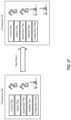
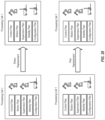
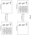
- Figure 7 illustrates an example Software Defined Manufacturing Reference Architecture 700 in accordance with embodiments of the present invention. Use cases are disclosed below to show how this proposed model can address real industry problems. For ease of understanding, the following description is focused on examples based on a manufacturing context. As such the terminology used relates specifically to manufacturing. However, it will be appreciated that the same techniques can be equally applied to industrial facilities and processes other than manufacturing.
- the reference architecture 700 includes a management and planning layer 702, a supervision and control layer 704 and a field layer 706 composed of physical resources of the industrial facility such as industrial devices 406, loading docks, storage areas and working areas.
- the planning, supervision and control layers 702 and 704 may be implemented as one or more computer systems as described above with reference to figures 1A and 1B , and may form part or all of the core network 410 described above.
- the planning layer 702 includes an Internet of Things (loT) cloud 708, a planner 710 and a database 712, while the supervision and control layer 704 includes a scheduler 714, a supervisor 716, a controller 718, a mutual exclusion (MUTEX) server 720, a PTP server 722 and a Position server 724.
- LoT Internet of Things
- MUTEX mutual exclusion
- the field layer 706 may comprise physical resources and a virtualization layer that operates to present virtualized resources to upper layers, in a manner directly analogous to that described above with reference to Figure 2 .
- the functions and services of the management and planning layer 702 and supervision and control layer 704 may be implemented as applications 120 executing in virtual machines 210 or containers 211 hosted by an application platform 206, and using virtualized resources of the industrial facility presented to the application platform 206 by the virtualization layer 204.
- This reference architecture 700 is an abstract layered structure, that defines three abstraction layers:
- the example reference model of Figure 7 has white boxes which indicate functions having counterparts in conventional systems (e.g. in ROS industrial and/or IEC standards).
- the present description invention describes enhancements to their conventional functionality, and complements legacy functional blocks with new functional blocks and new interactions to fulfill requirements of Industry 4.0, ROS Industrial and IEC simultaneously.
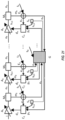
- FIG 8 illustrates an industrial facility 800 such as a manufacturing floor in which a radio access network 402 comprising a set of four adjacent cells 408 is deployed.
- each cell 408 may be defined by any suitable combination of geography, frequency, Radio Access Technology (RAT), modulation scheme and access node identifiers.
- RAT Radio Access Technology
- conventional hand-over techniques based on signal strength or radio signal coverage, for example
- mobile devices such as autonomous vehicles and AGVs
- fixed "geographical" boundaries between adjacent cells 408 may be defined within the industrial facility 800, and hand-over of a mobile device from one cell to another triggered by the location (and/or speed and direction) of the mobile device within the industrial facility 800.
- FIG 8 also illustrates an alternative embodiment, in which MPI 802D encompasses industrial devices 406 located in two difference cells 408C and 408D.
- the required inter-cell packet flows may make it more difficult to meet low latency demands of fine control functions.
- an MPI 802 may span two or more cells 408.
- the Planner 710 is responsible for taking manufacturing orders and breaking it down into fine steps.
- Each step in a manufacturing process (MP), and the MP as a whole, is a logical set that is specified by a collection of resources and one or more plans, such as, for example, a motion plan, a mobility plan, a task plan, a control plan, a supervision plan and a calibration plan.
- An MP is defined by a Planner and takes places in one or more MPls, that means, the MP is instantiated in one or more MPls to process an order.
- the loT Cloud 708 is responsible for collecting alarms and equipment status so that the consolidated information can be displayed on-demand.
- the database 712 may be subdivided as follows:
- the scheduler 714 is responsible for triggering the execution of manufacturing process definitions through one or more processing plans received from the planner 710 by:
- the PTP server 722 is responsible to provide a constant time reference across all nodes in the SDM reference model. It ensures all entities are time synchronized so that the tasks described in the collection of plans can be executed correctly.
- the PTP server can be substituted by any high accuracy time synchronization server.
- the Position server 724 is responsible to monitor and track the location of industrial devices 406 (and especially mobile devices) within the industrial facility.
- the manufacturing processing instance may include a controller 718, supervisor 716 and multiple industrial devices 406, at least some of which may be mobile devices.
- the supervisor 716 is the entity that handles or reacts to synchronous and asynchronous events originating inside the framework, for example as alarms from controllers of manufacturing processes or alarms resulting from monitoring determined properties of the manufacturing processes.
- the Controller 718 controls the execution of the plans to each of the Industrial Devices 406 under its control.
- FIG 9 is a flowchart describing an example process in accordance with embodiments of the present invention. Some steps in the flowchart will be explained further in the following subsections Step 906: Scheduler creates a Manufacturing Process Instance (MPI)
- MPI Manufacturing Process Instance
- Reception of an order may trigger the Planner 710 to create an MP which can originate one or more MPI(s).
- An MPI is created by the scheduler 714 in response to a request from the planner 710 which sends a Manufacturing Process specification to the scheduler to create one or more corresponding MPls.
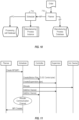
- Figure 11 illustrates an example sequence of messages to create an MPI.
- the scheduler 714 may verify that there are sufficient physical resources in the SDM resource pool to meet the requirements specified in the MP. If enough resources are available, the MPI is created and resources are allocated to it.
- Step 908 Scheduler allocates resources. Allocation of resources involves allocating Industrial Devices and allocating communication channels.
- Step 918 Scheduler 714 handles Mobile Industrial Device 406 Handover to a new MPI.
- Mobile Industrial Device 406 handover is done when the Industrial Device 406 moves between different MPls.
- the Handover Engine operating as part of the Scheduler, receives a Handover Event.
- the MPI allocation and destruction of the entity representation of the Industrial Device 406 that is to be handed over happens over the 4G/5G channel and the relevant Processing Cell Database is updated to reflect the changes.
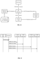
- Figure 13 illustrates an example message sequence of an industrial device handover process. An event is generated and sent to the Scheduler which handles the event.
- the Scheduler deletes the device from the Controller and Supervisor of the corresponding 1 st MPI to which the device is allocated.
- the Scheduler adds the device to the Controller and the Supervisor of the 2 nd (target) MPI that is to receive the device.
- the handover takes place by deleting the Industrial Device 406 from the first MPI and adding it to the second MPI.
- Deleting and adding Industrial Device 406 to a new MPI as illustrated by Figure 13 implies no-disruption of the industrial process implemented by the 1 st MPI. Otherwise the handover might not be successful, or one or more additional actions may be taken such as a shutdown of the 1st MPI by the Supervisor.
- Step 914 Scheduler updates MPI states.
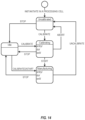
- Figure 14 shows example states of a manufacturing process instance (MPI). If an MPI is uncalibrated, a manufacturing process may not be executed to process an order. In some embodiments, the MPI must be calibrated before running a manufacturing process.
- MPI manufacturing process instance
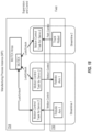
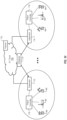
- FIG. 15 shows example SDM functional blocks and interfaces between these functional blocks.
- an MPI has the following main blocks:
- Shared functional blocks are blocks whose instances are shared or communicates with different MPls. These are:
- An SDM framework may contain two types of communication interfaces as follows:
- FIG 15 also shows example interfaces of the SDM framework which may include:
- the SDM executes a manufacturing process (MP) in an MPI.
- An MPI couples a processing cell (PC) to an MP.
- PC processing cell
- a unique MP can run in multiple MPls. Each MPI is associated with different PCs and producing a copy of the specified output for the order in the MP specification.
- Figure 16 shows an auto assembly line as an example realization of an MPI.
- An MPI can have several Industrial Devices 406 collaborating to satisfy an order.
- Each MPI is made up of functional blocks including Controller, Supervisor and industrial devices, with instruction from the Planner and Scheduler.
- the Planner is responsible for taking manufacturing orders and generate manufacturing processes which are specified with plans.
- the planning of a manufacturing process may involve any one or more of the following types of planning:
- Industrial Devices 406 such as Industrial Device 406 arms need to be able to carry out high-level task planning in conjunction with low-level motion planning.
- Task planning is needed to determine long-term strategies such as whether to stop the conveyor belt to grab the part to put in the autonomous vehicle.
- the motion planning is required for computing the actual movements that the Industrial Device 406 should carry out.
- TMP Task-Motion Planning
- a mobility plan describes how a mobile Industrial Device 406 travels inside an MPI and/or outside to cross to another MPI.
- the path followed by a mobile Industrial Device 406 can include the Industrial Device 406 being added and removed to different processing cells such as MC or MPI during its running. Therefore, a mobility plan may include either one or both of:
- a control plan contains the configuration of each fine control and the coarse control plan of the streamline.
- a supervision plan contains specifications for at least one of:
- a Calibration Plan involves performing the initial calibration of the various sensors in the Industrial Devices 406 in the manufacturing plant in order to aid in obtaining accurate sensor and meter values for the coarse and fine controllers.
- the Scheduler 714 may be responsible for one or more of:
- the Controller 718 controls the execution of the plans which might include motion, calibration, and control plans.
- Example functional subblocks of the Controller are illustrated in Figure 17 , and are described below:
- the Supervisor 716 handles or reacts to synchronous and asynchronous events originated inside the framework as alarms from controllers of manufacturing processes or alarms resulting from monitoring determined properties of the manufacturing processes.
- Every supervision plan sent to the supervisor 716 by the planner 710 triggers a new action that might include starting agents for monitoring QA parameters, adding event filters, adding event forwarders, creating scripts to execute actions to handle events.
- the foregoing description discussed high-level architecture, functional blocks and interfaces for implementing SDM in accordance with embodiments of the present invention.
- the following description provides a context of how these can be used to solve Industry 4.0 challenges.
- the SDM may support the following use cases of changes in manufacturing cells and manufacturing processes which are not supported by current solutions.
- a streamline models the flow of activities performed by Industrial Devices 406 to achieve a given goal such as:
- Tasks A task is a set of computation procedures performed, periodically or not. Examples of tasks are Linux threads and Linux processes. Real-time tasks are guaranteed to be started before a due-time in a concurrent operating system.
- a streamline may contain any one or more of the following real-time tasks:
- MUTEXes Sometimes Industrial Devices 406 need exclusive access to shared resources such as a manufactured part for Industrial Device 406 arms or access corridor in a floor for an autonomous vehicle. These types of accesses need to be coordinated so that the Industrial Devices 406 do not interfere with each other or generate collisions.
- This exclusive access can be implicitly programmed in the TMP or mobility plans. However, these plans are very hard to be done within the complex manufacturing process, some are probabilistically guaranteed to be found by an algorithm and some are prototyped using off-line programming [4].
- SDM provides mutual exclusive objects, or MUTEXes.
- MUTEXes mutual exclusive objects
- the Industrial Devices 406 need to own the MUTEX before accessing that resource. This guarantees that only one Controller 718 or one Industrial Device 406 can access the resource at any given time, and so helps to prevent collisions.
- Industrial Devices 406 that want to access the resource while it is being accessed by another Industrial Device 406 will wait in a MUTEX queue. Once an Industrial Device 406 finishes its access, it frees the MUTEX and the next Industrial Device 406 in the MUTEX queue can have access.
- Control tasks defined in SDM are typically real-time. Therefore, the isochronous real-time communication with low latency, low jitter and high reliability must be used to implement network MUTEXes. These requirements are typical of Time Sensitive Networks (TSN).
- TSN Time Sensitive Networks
- MUTEXes have a MUTEX ID and owner associated to them:
- Each manufacturing process instance has an interface to MUTEX server 720 or a MUTEX area where MUTEXes can be created, maintained and destroyed. Streamline tasks can access a MUTEX in this area through the naming services.
- MUTEXes may be created, accessed and destroyed through a network protocol.
- the network protocol may have the following synchronous messages:
- the MUTEX protocol should preferably use a real-time isochronous protocol with very low latency and reliability communications.
- FIG 18 illustrates an example in which two MUTEXes are used to protect access to a manufactured part in an MPI, and access to an autonomous vehicle.
- the TMP plan for streamline 1 defines two motion control tasks.
- the first motion control task controls the Industrial Device 406 arm 1 which does some manufacturing task on the part.
- the second motion control task controls the second Industrial Device 406 arm which grabs the part and put it inside the autonomous vehicle.
- the autonomous vehicle will delivery to the destination which is done by the path control task defined in the path plan.
- Figure 19 shows an example sequence of lock and unlock operations done by all three tasks to coordinate the whole manufacturing process from starting to manufacture the part to transporting it to the destination.
- Control plans can define a fine control or a coarse control (see the definition in the background section).
- Control plans may be written using any of the IEC 61131-3 Programming Languages, if desired.
- the process of generating a control plan may be done through an automated process that takes orders and resources specifications from the Cell Processing database and generates the control plan using Structured Text, for example.
- the control plan may be made part of the Manufacturing Process which is defined by the planner.
- the fine control and coarse control are the implementation of closed-loop controls. They are integrated in such a way that they work together with different time granularity of measurement and gain, to adjust one or more variables as described above.
- Figure 20 illustrates the parallel configuration of the coarse/fine CLGC. In this configuration, the fine CLGC are independent of each other. The behavior of one loop does not affect the behavior of the other loops.
- Figure 21 illustrates an example serial configuration of the coarse/fine CLGC. In a serial configuration, CLGC loops are cascaded. Thus, the behavior of any CLGC loop influences the behavior of the other CLGC loop.
- Fine control happens in the fine controller ( C i ).
- C i is typically an Industrial Device specific function, but the Industrial Device controller can supply a fine controller based on any control function such as one of the previously defined types of controller.
- a VGP A i can control the rear wheel speed of an autonomous car to keep it constant.
- the corresponding meter M i can sense the speed has deviated and the car will have to accelerate.
- the corresponding e i can give an initial correction d i in terms of acceleration increase.
- the floor can be slippery which is sensed by a traction sensor installed in the wheels.
- a corresponding function ⁇ i can negatively feedback C i to avoid the full speed increase giving by d i .
- Other examples of ⁇ i can model control for temperature, frequency, and humidity.
- Fine Controller Implemented in the Industrial Device 406.
- the fine controller is implemented in an Industrial Device 406 controlled by the Industrial Device Controller through CFCP protocol
- closed-loop gain control capability request messages are sent by the Industrial Device Controller to the fine controller which replies with the confirmation of the capability, that is, the capability is allocated by the fine controller in the Industrial Device 406 controlled by the Industrial Device Controller.
- the fine controller can be implemented in the Industrial Device Controller to control a VGP implemented at the Industrial Device 406 having feedback signal from meters close to the Industrial Device 406 and environmental sensors.
- the fine controller at Industrial Device Controller can discover the capabilities of VGP, meter, and sensor characteristics through the CFCP capability negotiation messages for VPG, meters and sensors respectively.
- Coarse control happens in the coarse controller ( G ).
- the general control function G combines all the errors e i and data from m sensors s i to generate a control vector [ p 1 , p 2 ,.., p n ] .
- Each element in this vector is a control value p i which is applied together with d i to the fine controller C i . Therefore, G is a composition of closed control gain loop controllers, each controller generating a signal p i .
- Such an individual controller can be from one of the controller types defined above.
- the Coarse and Fine Control Protocol may be a peer-to-peer client/server protocol. It may be provided as an application layer transport protocol designed specifically to transport packet data from/to devices controlled by the CLGC controller to/from the CLGC controller:
- Requirements of the CFCP may include any one or more of the following:
- CFCP packets should preferably use an average of two 4G resource blocks.
- CFCP packets for non-real-time transmission These packets are used for capability negotiation and association negotiation. There is no restriction to the size of the CFCP packet.
- CFCP packet for synchronous real-time transmission These packets are used for synchronous real-time transmissions. These packets should preferably fit in two LTE resource blocks on average.
- CFCP packet for isochronous real-time transmission These packets are used for isochronous real-time transmissions. These packets should preferably fit in two LTE resource blocks on average.
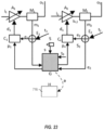
- Example 1 Figure 22 illustrates a line of autonomous vehicles 406 used to transport manufactured parts from a manufacturing process.
- the autonomous vehicles 406 follow one after another. They are separated by a variable distance (d), although the differences in the distances between autonomous vehicles are kept as minimal as possible.
- Each autonomous vehicle 406 has two electrical motors.
- Figure 23 illustrates the control of these motors of an autonomous vehicle 406 modelled as a streamline.
- the two motors are controlled by fine CLGC controllers (C 1 and C 2 ) that commands the rotation of each motor.
- the feedback signals for these two controllers come from the tachometers or encoders (M 1 and M 2 ).
- the distance between the autonomous vehicles is controlled by a coarse CLGC controller (G).
- the feedback signal for G comes from one of the proximity sensors (S) in each autonomous vehicle.
- a supervisor (H) receives events (speed alarms) from the coarse controllers in case it is not able to correct the errors.
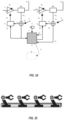
- the two front wheels can turn by means of their wheel servos. They are controlled by the path controller that follows a path plan.
- Figure 24 shows this path control modelled as a streamline.
- the two fine controllers (C 1 and C 2 ) control the angles of the wheels and the coarse control (G) controls the angle of the autonomous vehicle.
- These controllers receive the feedback signal from the meters (M, and M 2 ) that measures that angle with a fixed reference such as the middle border of the lane (yellow line of the road) or the curb line of the road.
- This example illustrates a case where the streamlines are cascaded in a sequence.
- the output of a streamline is the input of the next streamline, unless it is the last streamline in the sequence.
- the output of the last streamline is the output of the streamline sequence.
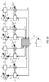
- FIG 25 illustrates an example of an assembly line.
- the assembly line contains four Industrial Device 406 arms.
- the Industrial Device 406 arms are placed along a line performing some manufacturing task in a part passing through the Industrial Devices 406.
- Each Industrial Device 406 has a determined time to due time the task. After the due time, the next Industrial Device 406 can start its task on the manufactured part being produced.
- the streamline illustrated in Figure 26 models the control for the servos in each Industrial Device 406 arm.
- the streamline contains four fine control loops in cascade, each controlling the speed of the servos and one coarse control loop with a coarse control of these speeds after some speed threshold.
- Supervision is the control with the largest response time. Supervision control permits a longer time interval than CLGC, taking actions to correct problems detected during the fine and coarse CLGC and cannot be corrected by varying the gain from VGPs.
- the supervision is characterized by the self-healing property which is the supervision property to correct some defect or problem in the MPI following an abnormal manufacturing condition.
- the Supervision functional block monitors the control functions of the fine and coarse CLGC. Additionally, the supervision can monitor properties of environmental sensors in the MPI and it might raise alarms to loT Cloud 708 or performing self-healing operations if pre-determined conditions are not met.
- Control stability It tells how often the output deviates from the target value.
- Control convergence it is the time in average for the PV to converge to PS (or very close to it).
- the supervisor triggers a self-healing action which will apply some predefined correction external to the control functional block such as:
- the manufacturing process may specify quality assurance control parameters which triggers the instantiation of supervision monitors for these parameters. Depending on the supervision plan these monitors can trigger events if the parameters are not met.
- the MPI Before executing a manufacturing process, the MPI verifies the state of the processing cell to determine whether or not any calibration is required. If the PC needs calibration, the MPI moves to uncalibrated state and may start a calibration procedure for the processing cell during a maintenance window. It is costly to discover any defective product being manufactured and it is extremely costly to pause any ongoing manufacturing process because any unplanned interruption has monetary impact. In other words, the product value that can be manufactured during the stoppage is not able to realize.
- a calibration plan may contain any one or more of:
- Production scaling It is the increase or decrease by the software interface of the production of orders in a manufacturing process.
- Figure 27 illustrates an example of an order to increase the production capacity. This action on SDM can be triggered by the SDM Planner or by a human operator through the SDM software interface.
- Production Relocation it is the physical relocation of a manufacturing process to a new area in a factory. This use case is illustrated in Figure 29 . This action can be triggered automatically through the SDM supervision, by the SDM Planner or by a human operator through the software interface of the SDM.
- FIG 30 illustrates an example cloud-based deployment of Software Defined Manufacturing.
- the loT cloud represents an information network implemented using cloud technologies.
- the loT cloud implements several services such as manufacturing order dispatching, SDM health reporting, SDM management.
- the Planner is responsible for generating the manufacturing process definition, each streamline comprising a manufacturing process and its correlated plans (control plan, supervision plan, motion plan, transport plan) of the streamline.
- the planner also keeps the centralized database with physical resource definitions.
- the scheduler can be situated in the cloud and it dispatches instruction to the controller and supervisor.
- the controller and supervisor can reside in the cloud as well if the real-time responses and closed-loop controls are not needed in the deployment. For this discussion, we assume they are edge computing and residing on the premise.
- the scheduler is responsible for instantiating the cells to produce the orders using the streamline definitions and the centralized resource database. The scheduler allocates Industrial Devices 406 and any other physical resources in a processing cell. It also operates the processing (start, pause, stop).
Landscapes
- Engineering & Computer Science (AREA)
- General Engineering & Computer Science (AREA)
- Manufacturing & Machinery (AREA)
- Quality & Reliability (AREA)
- Physics & Mathematics (AREA)
- General Physics & Mathematics (AREA)
- Automation & Control Theory (AREA)
- Health & Medical Sciences (AREA)
- Computing Systems (AREA)
- General Health & Medical Sciences (AREA)
- Medical Informatics (AREA)
- Computer Networks & Wireless Communication (AREA)
- Signal Processing (AREA)
- Mobile Radio Communication Systems (AREA)
Claims (11)
- System, umfassendmindestens einen Zugangsknoten (404), der dazu konfiguriert ist, Signale zu und von Industrievorrichtungen (406) innerhalb von mindestens zwei Zellen (408) eines zellulären Kommunikationsnetzwerks (400), das in einer Fertigungsanlage eingesetzt ist, drahtlos zu übertragen und zu empfangen, wobei das zelluläre Kommunikationsnetzwerk 5G-NR-Standards entspricht und Fähigkeiten von ultrazuverlässiger Kommunikation mit niedriger Latenz, URLLC-Fähigkeiten, aufweist;ein Computersystem, umfassend:eine Schnittstelle (108), die verbunden ist, um Signale zu und von dem Zugangsknoten unter Verwendung von URLLC zu übertragen und zu empfangen; undeine Verarbeitungsschaltung (104), die zu Folgendem konfiguriert ist:Definieren einer Fertigungsprozessinstanz, MPI, die Fertigungsvorgänge identifiziert, die erforderlich sind, um einen vorgegebenen Fertigungsprozess durchzuführen;Zuweisen einer oder mehrerer der Industrievorrichtungen zu der MPI, wobei jede zugewiesene Industrievorrichtung dazu konfiguriert ist, mindestens einen der identifizierten Fertigungsvorgänge durchzuführen; undImplementieren einer Steuerung (718), die dazu konfiguriert ist, jede der Industrievorrichtungen zu steuern, die der MPI zugewiesen sind, indem sie in jedem Zyklus eines iterativen Prozesses:unter Verwendung von URLLC ein Befehlssignal an eine ausgewählte der Industrievorrichtungen überträgt, die der MPI zugewiesen sind; undunter Verwendung von URLLC ein Antwortsignal von der ausgewählten der Industrievorrichtungen empfängt.
- System nach Anspruch 1, wobei die Industrievorrichtungen eines oder mehrere der Folgenden umfassen:Industrieroboter;Sensoren;Aktuatoren; undMaschinensteuerungen.
- System nach Anspruch 1, wobei das zelluläre Kommunikationsnetzwerk von einem öffentlichen Landmobilitätsnetzwerk, PLMN, durch eines oder mehrere der Folgenden isoliert ist:entweder eines oder beides aus einem Verschlüsselungsprotokoll und mindestens einem Verschlüsselungsschlüssel;räumliche Trennung; undHochfrequenzabschirmung.
- System nach Anspruch 1, wobei sich alle der Industrievorrichtungen, die der MPI zugewiesen sind, innerhalb einer gemeinsamen der Zellen des zellulären Kommunikationsnetzwerks befinden.
- System nach Anspruch 1, wobei sich mindestens eine der Industrievorrichtungen, die der MPI zugewiesen sind, innerhalb einer Zelle des Funkzugangsnetzwerks befindet und sich eine andere der Industrievorrichtungen, die der MPI zugewiesen sind, innerhalb einer anderen Zelle des zellulären Kommunikationsnetzwerks befindet.
- System nach Anspruch 1, wobei die Verarbeitungsschaltung ferner dazu konfiguriert ist, einen Supervisor (716) zu implementieren, der dazu konfiguriert ist, einen Betrieb einer jeden der Industrievorrichtungen, die der MPI zugewiesen sind, zu überwachen.
- System nach Anspruch 1, wobei die Verarbeitungsschaltung ferner dazu konfiguriert ist, einen MUTEX-Server (720) zu implementieren, der dazu konfiguriert ist, einen Zugriff durch die Industrievorrichtungen, die der MPI zugewiesen sind, auf Ressourcen der Fertigungsanlage zu steuern, die mit Industrieausrüstungen geteilt werden, die einer anderen MPI zugewiesen sind.
- System nach Anspruch 1, wobei die Verarbeitungsschaltung ferner dazu konfiguriert ist, einen Positionsserver (724) zu implementieren, der dazu konfiguriert ist, eine aktuelle Position jeder der Industrieausrüstungen, die der MPI zugewiesen sind, innerhalb der Fertigungsanlage aufzuzeichnen.
- System nach Anspruch 1, wobei das Antwortsignal Closed-Loop-Gain-Control-Daten, CLGC-Daten, umfasst.
- System nach Anspruch 1, wobei das Befehlssignal zumindest teilweise auf Folgendem basiert:
einem spezifischen Fertigungsvorgang, der mit der ausgewählten der Industrievorrichtungen verknüpft ist; und dem Antwortsignal, das von der ausgewählten der Industrievorrichtungen in einem vorherigen Zyklus des iterativen Prozesses empfangen wurde. - Computerimplementiertes Verfahren, umfassend:Drahtloses Übertragen und Empfangen von Signalen zu und von Industrievorrichtungen (406) innerhalb von mindestens zwei Zellen (408) eines zellulären Kommunikationsnetzwerks (400), das in einer Fertigungsanlage eingesetzt ist, wobei das zelluläre Kommunikationsnetzwerk 5G-NR-Standards entspricht und Fähigkeiten von ultrazuverlässiger Kommunikation mit niedriger Latenz, URLLC-Fähigkeiten, aufweist;Definieren einer Fertigungsprozessinstanz, MPI, die Fertigungsvorgänge identifiziert, die erforderlich sind, um einen vorgegebenen Fertigungsprozess durchzuführen;Zuweisen einer oder mehrerer der Industrievorrichtungen (406) zu der MPI, wobei jede zugewiesene Industrievorrichtung dazu konfiguriert ist, mindestens einen der identifizierten Fertigungsvorgänge durchzuführen; undImplementieren einer Steuerung (718), die dazu konfiguriert ist, jede der Industrievorrichtungen der MPI zu steuern, indem sie in jedem Zyklus eines iterativen Prozesses:unter Verwendung von URLLC ein Befehlssignal an eine ausgewählte der Industrievorrichtungen überträgt, die der MPI zugewiesen sind; undunter Verwendung von URLLC ein Antwortsignal von der ausgewählten der Industrievorrichtungen empfängt.
Applications Claiming Priority (2)
| Application Number | Priority Date | Filing Date | Title |
|---|---|---|---|
| US201962882261P | 2019-08-02 | 2019-08-02 | |
| PCT/IB2020/057218 WO2021024113A1 (en) | 2019-08-02 | 2020-07-30 | Software defined manufacturing in a cellular network |
Publications (3)
| Publication Number | Publication Date |
|---|---|
| EP4008097A1 EP4008097A1 (de) | 2022-06-08 |
| EP4008097B1 true EP4008097B1 (de) | 2024-09-11 |
| EP4008097C0 EP4008097C0 (de) | 2024-09-11 |
Family
ID=71994675
Family Applications (1)
| Application Number | Title | Priority Date | Filing Date |
|---|---|---|---|
| EP20753439.7A Active EP4008097B1 (de) | 2019-08-02 | 2020-07-30 | Softwaredefinierte fertigung in einem zellulären netzwerk |
Country Status (4)
| Country | Link |
|---|---|
| US (1) | US12468291B2 (de) |
| EP (1) | EP4008097B1 (de) |
| CN (1) | CN114144739B (de) |
| WO (1) | WO2021024113A1 (de) |
Families Citing this family (15)
| Publication number | Priority date | Publication date | Assignee | Title |
|---|---|---|---|---|
| US12417120B2 (en) | 2021-06-16 | 2025-09-16 | Fisher-Rosemount Systems, Inc. | Systems and methods for dynamically maintained redundancy and load balancing in software defined control systems for industrial process plants |
| US20220404812A1 (en) * | 2021-06-16 | 2022-12-22 | Fisher-Rosemount Systems, Inc. | Discovery Service in a Software Defined Control System |
| US12449789B2 (en) | 2021-06-16 | 2025-10-21 | Fisher-Rosemount Systems, Inc. | Security services in a software defined control system |
| US12321154B2 (en) | 2021-06-16 | 2025-06-03 | Fisher-Rosemount Systems, Inc. | Systems and methods for associating modules in a software defined control system for industrial process plants |
| US12314037B2 (en) | 2021-06-16 | 2025-05-27 | Fisher-Rosemount Systems, Inc | Systems and methods for associating modules in a software defined control system for industrial process plants |
| US12242245B2 (en) | 2021-06-16 | 2025-03-04 | Fisher-Rosemount Systems, Inc. | Discovery service in a software defined control system |
| US12210329B2 (en) | 2021-06-16 | 2025-01-28 | Fisher-Rosemount Systems, Inc. | Systems and methods for dynamically maintained redundancy and load balancing in software defined control systems for industrial process plants |
| US12535800B2 (en) | 2021-06-16 | 2026-01-27 | Fisher-Rosemount Systems, Inc. | Systems and methods for dynamically maintained redundancy and load balancing in software defined control systems for industrial process plants |
| WO2023274543A1 (en) * | 2021-07-01 | 2023-01-05 | Telefonaktiebolaget Lm Ericsson (Publ) | Precision time protocol link time error calibration using over-the-air synchronization |
| CN114726899A (zh) * | 2022-03-09 | 2022-07-08 | 上海有间建筑科技有限公司 | 一种智慧运维用日常巡检的管理系统及管理方法 |
| US12228897B2 (en) | 2022-07-18 | 2025-02-18 | Fisher-Rosemount Systems, Inc. | Securing access of a process control or automation system |
| US12476973B2 (en) | 2022-07-18 | 2025-11-18 | Fisher-Rosemount Systems, Inc. | Authentication/authorization framework for a process control or automation system |
| US20240118798A1 (en) * | 2022-10-10 | 2024-04-11 | Schneider Electric Systems Usa, Inc. | Configuration sourced direct from ethernet advanced physical layer field device |
| US12524389B2 (en) | 2022-10-20 | 2026-01-13 | Fisher-Rosemount Systems, Inc. | Enterprise engineering and configuration framework for advanced process control and monitoring systems |
| CN117596651A (zh) * | 2024-01-18 | 2024-02-23 | 煤炭科学技术研究院有限公司 | 工业设备的接入方法、装置、设备及存储介质 |
Family Cites Families (29)
| Publication number | Priority date | Publication date | Assignee | Title |
|---|---|---|---|---|
| US6801949B1 (en) * | 1999-04-12 | 2004-10-05 | Rainfinity, Inc. | Distributed server cluster with graphical user interface |
| US6819960B1 (en) | 2001-08-13 | 2004-11-16 | Rockwell Software Inc. | Industrial controller automation interface |
| US9565275B2 (en) | 2012-02-09 | 2017-02-07 | Rockwell Automation Technologies, Inc. | Transformation of industrial data into useful cloud information |
| US20040260405A1 (en) * | 2003-06-18 | 2004-12-23 | Ron Eddie | Modular monitoring, control and device management for use with process control systems |
| US7460865B2 (en) * | 2003-06-18 | 2008-12-02 | Fisher-Rosemount Systems, Inc. | Self-configuring communication networks for use with process control systems |
| US7323991B1 (en) * | 2005-05-12 | 2008-01-29 | Exavera Technologies Incorporated | System and method for locating and communicating with personnel and equipment in a facility |
| US9418263B2 (en) * | 2005-12-09 | 2016-08-16 | Tego, Inc. | Operating systems for an RFID tag |
| US8988223B2 (en) * | 2005-12-09 | 2015-03-24 | Tego Inc. | RFID drive management facility |
| JP2007233977A (ja) * | 2006-03-03 | 2007-09-13 | Oki Electric Ind Co Ltd | マルチタスクシステムの排他制御方法 |
| US7940749B2 (en) | 2007-09-15 | 2011-05-10 | Wei Lu | Common communication terminal architecture and method |
| US8413227B2 (en) * | 2007-09-28 | 2013-04-02 | Honeywell International Inc. | Apparatus and method supporting wireless access to multiple security layers in an industrial control and automation system or other system |
| EP2164033A1 (de) * | 2008-08-28 | 2010-03-17 | Siemens Aktiengesellschaft | Verfahren zur Auswahl von Geräteressourcen in einem Herstellungsverfahren |
| US8948067B2 (en) * | 2009-04-23 | 2015-02-03 | Honeywell International Inc. | Wireless controller grids for process control and other systems and related apparatus and method |
| US9350550B2 (en) * | 2013-09-10 | 2016-05-24 | M2M And Iot Technologies, Llc | Power management and security for wireless modules in “machine-to-machine” communications |
| US9971317B2 (en) * | 2014-03-26 | 2018-05-15 | Rockwell Automation Technologies, Inc. | Cloud-level industrial controller loop gain tuning based on industrial application type |
| US20150277407A1 (en) | 2014-03-27 | 2015-10-01 | Trane International Inc. | Location detection of control equipment in a building |
| US9958860B2 (en) * | 2014-05-01 | 2018-05-01 | Rockwell Automation Technologies, Inc. | Systems and methods for broadcasting data and data tags associated with an industrial automation system |
| US9720404B2 (en) * | 2014-05-05 | 2017-08-01 | Honeywell International Inc. | Gateway offering logical model mapped to independent underlying networks |
| US10649414B2 (en) * | 2015-03-27 | 2020-05-12 | Bühler AG | Adaptive cross plant control and steering system, and corresponding method thereof |
| CA3001790A1 (en) | 2015-10-13 | 2017-04-20 | Schneider Electric Industries Sas | Centralized management of a software defined automation system |
| US11000449B2 (en) | 2016-01-22 | 2021-05-11 | Hayward Industries, Inc. | Systems and methods for providing network connectivity and remote monitoring, optimization, and control of pool/spa equipment |
| WO2017165701A1 (en) * | 2016-03-25 | 2017-09-28 | Nebbiolo Technologies, Inc. | Fog Computing Facilitated Flexible Factory |
| US10375162B2 (en) * | 2016-07-22 | 2019-08-06 | Fisher-Rosemount Systems, Inc. | Process control communication architecture |
| US10595283B2 (en) * | 2016-11-22 | 2020-03-17 | Samsung Electronics Co., Ltd. | Method and apparatus for transmitting and receiving data of terminal |
| US10767885B2 (en) | 2017-03-09 | 2020-09-08 | Johnson Controls Technology Company | Building automation system with an energy optimization builder and generic data model designer |
| US10778378B2 (en) * | 2017-12-04 | 2020-09-15 | Samsung Electronics Co., Ltd | Method and apparatus for transmitting uplink data in wireless communication system |
| US11233594B2 (en) * | 2017-12-19 | 2022-01-25 | Qualcomm Incorporated | Time synchronization for wireless communications |
| US11533715B2 (en) * | 2019-02-08 | 2022-12-20 | Qualcomm Incorporated | Reliable low latency wireless communications |
| US12464041B2 (en) | 2019-02-13 | 2025-11-04 | Telefonaktiebolaget Lm Ericsson (Publ) | Industrial automation with 5G and beyond |
-
2020
- 2020-07-30 US US17/630,185 patent/US12468291B2/en active Active
- 2020-07-30 EP EP20753439.7A patent/EP4008097B1/de active Active
- 2020-07-30 WO PCT/IB2020/057218 patent/WO2021024113A1/en not_active Ceased
- 2020-07-30 CN CN202080054371.1A patent/CN114144739B/zh active Active
Non-Patent Citations (1)
| Title |
|---|
| PATEL DHRUVIN ET AL: "5G meets Time Sensitive Networking", 18 December 2018 (2018-12-18), pages 1 - 6, XP093047109, Retrieved from the Internet <URL:https://www.ericsson.com/en/blog/2018/12/5g-meets-time-sensitive-networking> [retrieved on 20230515] * |
Also Published As
| Publication number | Publication date |
|---|---|
| WO2021024113A1 (en) | 2021-02-11 |
| US12468291B2 (en) | 2025-11-11 |
| US20220283571A1 (en) | 2022-09-08 |
| EP4008097A1 (de) | 2022-06-08 |
| CN114144739A (zh) | 2022-03-04 |
| CN114144739B (zh) | 2025-07-04 |
| EP4008097C0 (de) | 2024-09-11 |
Similar Documents
| Publication | Publication Date | Title |
|---|---|---|
| EP4008097B1 (de) | Softwaredefinierte fertigung in einem zellulären netzwerk | |
| Baumann et al. | Wireless control for smart manufacturing: Recent approaches and open challenges | |
| US12416911B2 (en) | Modular process control system | |
| US11436544B2 (en) | System for managing an industrial workflow | |
| US10942251B2 (en) | Asset location and management system with distributed processing | |
| EP3440824B1 (de) | Kantenserver und verfahren zum betreiben eines kantenservers | |
| US20180332434A1 (en) | Events based asset location and management system | |
| JP2019514144A (ja) | フォグコンピューティング促進型フレキシブル工場 | |
| KR101940747B1 (ko) | IoT 기반의 공장 통합 관리 장치 | |
| WO2017127743A1 (en) | Cloud-based systems and methods for asset management | |
| CN106063221B (zh) | 用于在切换后用冗余设备建立安全通信的装置和方法 | |
| Külzer et al. | AI4Mobile: Use cases and challenges of AI-based QoS prediction for high-mobility scenarios | |
| Zeydan et al. | 6G wireless communications for industrial automation: Scenarios, requirements and challenges | |
| CN114051608A (zh) | 基于分布式事件的协调模型 | |
| US20240187356A1 (en) | Use of a curve section in a process control system | |
| CN120750976B (zh) | 基于人工智能的指挥调度管理方法及系统 | |
| Charpentier et al. | Advancing vertical services for 6g: Future directions and innovations | |
| US20240019852A1 (en) | Cloud edge network process automation control | |
| US20240098775A1 (en) | Method and network node for applying machine learning in a wireless communications network | |
| Zeydan et al. | The role of mobile communications for industrial automation: architecture, applications and challenges | |
| Grosjean et al. | 5G-Enabled Smart Manufacturing--A booklet by 5G-SMART | |
| Dang et al. | Open radio intelligent controller based wireless time sensitive networking for industry 5.0 | |
| Zannat | 5G Networks in Port Operations: Case Study Pori | |
| US12299009B2 (en) | Generating visualizations for deployment using edge compute modules and industrial design environments | |
| WO2022105992A1 (en) | TECHNIQUE FOR PERFORMING QoS CONTROL IN A CLOUD ROBOTICS SYSTEM |
Legal Events
| Date | Code | Title | Description |
|---|---|---|---|
| STAA | Information on the status of an ep patent application or granted ep patent |
Free format text: STATUS: UNKNOWN |
|
| STAA | Information on the status of an ep patent application or granted ep patent |
Free format text: STATUS: THE INTERNATIONAL PUBLICATION HAS BEEN MADE |
|
| PUAI | Public reference made under article 153(3) epc to a published international application that has entered the european phase |
Free format text: ORIGINAL CODE: 0009012 |
|
| STAA | Information on the status of an ep patent application or granted ep patent |
Free format text: STATUS: REQUEST FOR EXAMINATION WAS MADE |
|
| 17P | Request for examination filed |
Effective date: 20220215 |
|
| AK | Designated contracting states |
Kind code of ref document: A1 Designated state(s): AL AT BE BG CH CY CZ DE DK EE ES FI FR GB GR HR HU IE IS IT LI LT LU LV MC MK MT NL NO PL PT RO RS SE SI SK SM TR |
|
| DAV | Request for validation of the european patent (deleted) | ||
| DAX | Request for extension of the european patent (deleted) | ||
| STAA | Information on the status of an ep patent application or granted ep patent |
Free format text: STATUS: EXAMINATION IS IN PROGRESS |
|
| 17Q | First examination report despatched |
Effective date: 20230522 |
|
| REG | Reference to a national code |
Ref country code: DE Ref legal event code: R079 Free format text: PREVIOUS MAIN CLASS: H04L0029080000 Ipc: H04L0067120000 Ref document number: 602020037579 Country of ref document: DE |
|
| GRAP | Despatch of communication of intention to grant a patent |
Free format text: ORIGINAL CODE: EPIDOSNIGR1 |
|
| STAA | Information on the status of an ep patent application or granted ep patent |
Free format text: STATUS: GRANT OF PATENT IS INTENDED |
|
| RIC1 | Information provided on ipc code assigned before grant |
Ipc: H04L 67/12 20220101AFI20240328BHEP |
|
| INTG | Intention to grant announced |
Effective date: 20240426 |
|
| GRAS | Grant fee paid |
Free format text: ORIGINAL CODE: EPIDOSNIGR3 |
|
| GRAA | (expected) grant |
Free format text: ORIGINAL CODE: 0009210 |
|
| STAA | Information on the status of an ep patent application or granted ep patent |
Free format text: STATUS: THE PATENT HAS BEEN GRANTED |
|
| AK | Designated contracting states |
Kind code of ref document: B1 Designated state(s): AL AT BE BG CH CY CZ DE DK EE ES FI FR GB GR HR HU IE IS IT LI LT LU LV MC MK MT NL NO PL PT RO RS SE SI SK SM TR |
|
| REG | Reference to a national code |
Ref country code: GB Ref legal event code: FG4D |
|
| REG | Reference to a national code |
Ref country code: CH Ref legal event code: EP |
|
| REG | Reference to a national code |
Ref country code: DE Ref legal event code: R096 Ref document number: 602020037579 Country of ref document: DE |
|
| REG | Reference to a national code |
Ref country code: IE Ref legal event code: FG4D |
|
| U01 | Request for unitary effect filed |
Effective date: 20240911 |
|
| U07 | Unitary effect registered |
Designated state(s): AT BE BG DE DK EE FI FR IT LT LU LV MT NL PT RO SE SI Effective date: 20240930 |
|
| PG25 | Lapsed in a contracting state [announced via postgrant information from national office to epo] |
Ref country code: NO Free format text: LAPSE BECAUSE OF FAILURE TO SUBMIT A TRANSLATION OF THE DESCRIPTION OR TO PAY THE FEE WITHIN THE PRESCRIBED TIME-LIMIT Effective date: 20241211 |
|
| PG25 | Lapsed in a contracting state [announced via postgrant information from national office to epo] |
Ref country code: GR Free format text: LAPSE BECAUSE OF FAILURE TO SUBMIT A TRANSLATION OF THE DESCRIPTION OR TO PAY THE FEE WITHIN THE PRESCRIBED TIME-LIMIT Effective date: 20241212 |
|
| PG25 | Lapsed in a contracting state [announced via postgrant information from national office to epo] |
Ref country code: HR Free format text: LAPSE BECAUSE OF FAILURE TO SUBMIT A TRANSLATION OF THE DESCRIPTION OR TO PAY THE FEE WITHIN THE PRESCRIBED TIME-LIMIT Effective date: 20240911 |
|
| PG25 | Lapsed in a contracting state [announced via postgrant information from national office to epo] |
Ref country code: RS Free format text: LAPSE BECAUSE OF FAILURE TO SUBMIT A TRANSLATION OF THE DESCRIPTION OR TO PAY THE FEE WITHIN THE PRESCRIBED TIME-LIMIT Effective date: 20241211 Ref country code: ES Free format text: LAPSE BECAUSE OF FAILURE TO SUBMIT A TRANSLATION OF THE DESCRIPTION OR TO PAY THE FEE WITHIN THE PRESCRIBED TIME-LIMIT Effective date: 20240911 |
|
| PG25 | Lapsed in a contracting state [announced via postgrant information from national office to epo] |
Ref country code: RS Free format text: LAPSE BECAUSE OF FAILURE TO SUBMIT A TRANSLATION OF THE DESCRIPTION OR TO PAY THE FEE WITHIN THE PRESCRIBED TIME-LIMIT Effective date: 20241211 Ref country code: NO Free format text: LAPSE BECAUSE OF FAILURE TO SUBMIT A TRANSLATION OF THE DESCRIPTION OR TO PAY THE FEE WITHIN THE PRESCRIBED TIME-LIMIT Effective date: 20241211 Ref country code: HR Free format text: LAPSE BECAUSE OF FAILURE TO SUBMIT A TRANSLATION OF THE DESCRIPTION OR TO PAY THE FEE WITHIN THE PRESCRIBED TIME-LIMIT Effective date: 20240911 Ref country code: GR Free format text: LAPSE BECAUSE OF FAILURE TO SUBMIT A TRANSLATION OF THE DESCRIPTION OR TO PAY THE FEE WITHIN THE PRESCRIBED TIME-LIMIT Effective date: 20241212 Ref country code: ES Free format text: LAPSE BECAUSE OF FAILURE TO SUBMIT A TRANSLATION OF THE DESCRIPTION OR TO PAY THE FEE WITHIN THE PRESCRIBED TIME-LIMIT Effective date: 20240911 |
|
| PG25 | Lapsed in a contracting state [announced via postgrant information from national office to epo] |
Ref country code: IS Free format text: LAPSE BECAUSE OF FAILURE TO SUBMIT A TRANSLATION OF THE DESCRIPTION OR TO PAY THE FEE WITHIN THE PRESCRIBED TIME-LIMIT Effective date: 20250111 |
|
| PG25 | Lapsed in a contracting state [announced via postgrant information from national office to epo] |
Ref country code: SM Free format text: LAPSE BECAUSE OF FAILURE TO SUBMIT A TRANSLATION OF THE DESCRIPTION OR TO PAY THE FEE WITHIN THE PRESCRIBED TIME-LIMIT Effective date: 20240911 |
|
| PG25 | Lapsed in a contracting state [announced via postgrant information from national office to epo] |
Ref country code: CZ Free format text: LAPSE BECAUSE OF FAILURE TO SUBMIT A TRANSLATION OF THE DESCRIPTION OR TO PAY THE FEE WITHIN THE PRESCRIBED TIME-LIMIT Effective date: 20240911 Ref country code: PL Free format text: LAPSE BECAUSE OF FAILURE TO SUBMIT A TRANSLATION OF THE DESCRIPTION OR TO PAY THE FEE WITHIN THE PRESCRIBED TIME-LIMIT Effective date: 20240911 |
|
| PG25 | Lapsed in a contracting state [announced via postgrant information from national office to epo] |
Ref country code: SK Free format text: LAPSE BECAUSE OF FAILURE TO SUBMIT A TRANSLATION OF THE DESCRIPTION OR TO PAY THE FEE WITHIN THE PRESCRIBED TIME-LIMIT Effective date: 20240911 |
|
| PLBE | No opposition filed within time limit |
Free format text: ORIGINAL CODE: 0009261 |
|
| STAA | Information on the status of an ep patent application or granted ep patent |
Free format text: STATUS: NO OPPOSITION FILED WITHIN TIME LIMIT |
|
| 26N | No opposition filed |
Effective date: 20250612 |
|
| U20 | Renewal fee for the european patent with unitary effect paid |
Year of fee payment: 6 Effective date: 20250728 |
|
| PGFP | Annual fee paid to national office [announced via postgrant information from national office to epo] |
Ref country code: GB Payment date: 20250728 Year of fee payment: 6 |