EP4007304A1 - Ohrstück für ein hörgerät, kuppel und ohrstückteil - Google Patents
Ohrstück für ein hörgerät, kuppel und ohrstückteil Download PDFInfo
- Publication number
- EP4007304A1 EP4007304A1 EP21208724.1A EP21208724A EP4007304A1 EP 4007304 A1 EP4007304 A1 EP 4007304A1 EP 21208724 A EP21208724 A EP 21208724A EP 4007304 A1 EP4007304 A1 EP 4007304A1
- Authority
- EP
- European Patent Office
- Prior art keywords
- earpiece
- dome
- vent
- vent aperture
- housing
- Prior art date
- Legal status (The legal status is an assumption and is not a legal conclusion. Google has not performed a legal analysis and makes no representation as to the accuracy of the status listed.)
- Pending
Links
- 239000012530 fluid Substances 0.000 claims abstract description 88
- 238000004891 communication Methods 0.000 claims abstract description 75
- 210000000613 ear canal Anatomy 0.000 claims abstract description 36
- 238000003780 insertion Methods 0.000 claims abstract description 8
- 230000037431 insertion Effects 0.000 claims abstract description 8
- 230000007246 mechanism Effects 0.000 claims description 61
- 238000007781 pre-processing Methods 0.000 description 14
- 210000003454 tympanic membrane Anatomy 0.000 description 12
- 210000002939 cerumen Anatomy 0.000 description 7
- 230000007257 malfunction Effects 0.000 description 5
- 230000008901 benefit Effects 0.000 description 4
- 239000012528 membrane Substances 0.000 description 4
- 230000015556 catabolic process Effects 0.000 description 3
- 238000006731 degradation reaction Methods 0.000 description 3
- 230000013011 mating Effects 0.000 description 3
- 238000013022 venting Methods 0.000 description 3
- 206010011878 Deafness Diseases 0.000 description 2
- 210000000883 ear external Anatomy 0.000 description 2
- 230000000694 effects Effects 0.000 description 2
- 230000010370 hearing loss Effects 0.000 description 2
- 231100000888 hearing loss Toxicity 0.000 description 2
- 208000016354 hearing loss disease Diseases 0.000 description 2
- 238000002372 labelling Methods 0.000 description 2
- 238000004519 manufacturing process Methods 0.000 description 2
- 238000012986 modification Methods 0.000 description 2
- 230000004048 modification Effects 0.000 description 2
- 238000012545 processing Methods 0.000 description 2
- 230000005236 sound signal Effects 0.000 description 2
- 238000004140 cleaning Methods 0.000 description 1
- 239000013536 elastomeric material Substances 0.000 description 1
- 230000006870 function Effects 0.000 description 1
- 239000000463 material Substances 0.000 description 1
- 238000000034 method Methods 0.000 description 1
- 230000037361 pathway Effects 0.000 description 1
- 229920001296 polysiloxane Polymers 0.000 description 1
- 239000012858 resilient material Substances 0.000 description 1
- 238000007789 sealing Methods 0.000 description 1
- 239000003566 sealing material Substances 0.000 description 1
- 238000005549 size reduction Methods 0.000 description 1
- 238000004513 sizing Methods 0.000 description 1
- 230000002123 temporal effect Effects 0.000 description 1
Images


Classifications
-
- H—ELECTRICITY
- H04—ELECTRIC COMMUNICATION TECHNIQUE
- H04R—LOUDSPEAKERS, MICROPHONES, GRAMOPHONE PICK-UPS OR LIKE ACOUSTIC ELECTROMECHANICAL TRANSDUCERS; DEAF-AID SETS; PUBLIC ADDRESS SYSTEMS
- H04R25/00—Deaf-aid sets, i.e. electro-acoustic or electro-mechanical hearing aids; Electric tinnitus maskers providing an auditory perception
- H04R25/48—Deaf-aid sets, i.e. electro-acoustic or electro-mechanical hearing aids; Electric tinnitus maskers providing an auditory perception using constructional means for obtaining a desired frequency response
-
- H—ELECTRICITY
- H04—ELECTRIC COMMUNICATION TECHNIQUE
- H04R—LOUDSPEAKERS, MICROPHONES, GRAMOPHONE PICK-UPS OR LIKE ACOUSTIC ELECTROMECHANICAL TRANSDUCERS; DEAF-AID SETS; PUBLIC ADDRESS SYSTEMS
- H04R1/00—Details of transducers, loudspeakers or microphones
- H04R1/10—Earpieces; Attachments therefor ; Earphones; Monophonic headphones
- H04R1/1016—Earpieces of the intra-aural type
-
- H—ELECTRICITY
- H04—ELECTRIC COMMUNICATION TECHNIQUE
- H04R—LOUDSPEAKERS, MICROPHONES, GRAMOPHONE PICK-UPS OR LIKE ACOUSTIC ELECTROMECHANICAL TRANSDUCERS; DEAF-AID SETS; PUBLIC ADDRESS SYSTEMS
- H04R1/00—Details of transducers, loudspeakers or microphones
- H04R1/10—Earpieces; Attachments therefor ; Earphones; Monophonic headphones
- H04R1/1091—Details not provided for in groups H04R1/1008 - H04R1/1083
-
- H—ELECTRICITY
- H04—ELECTRIC COMMUNICATION TECHNIQUE
- H04R—LOUDSPEAKERS, MICROPHONES, GRAMOPHONE PICK-UPS OR LIKE ACOUSTIC ELECTROMECHANICAL TRANSDUCERS; DEAF-AID SETS; PUBLIC ADDRESS SYSTEMS
- H04R1/00—Details of transducers, loudspeakers or microphones
- H04R1/20—Arrangements for obtaining desired frequency or directional characteristics
- H04R1/22—Arrangements for obtaining desired frequency or directional characteristics for obtaining desired frequency characteristic only
- H04R1/28—Transducer mountings or enclosures modified by provision of mechanical or acoustic impedances, e.g. resonator, damping means
- H04R1/2807—Enclosures comprising vibrating or resonating arrangements
- H04R1/2815—Enclosures comprising vibrating or resonating arrangements of the bass reflex type
- H04R1/2823—Vents, i.e. ports, e.g. shape thereof or tuning thereof with damping material
- H04R1/2826—Vents, i.e. ports, e.g. shape thereof or tuning thereof with damping material for loudspeaker transducers
-
- H—ELECTRICITY
- H04—ELECTRIC COMMUNICATION TECHNIQUE
- H04R—LOUDSPEAKERS, MICROPHONES, GRAMOPHONE PICK-UPS OR LIKE ACOUSTIC ELECTROMECHANICAL TRANSDUCERS; DEAF-AID SETS; PUBLIC ADDRESS SYSTEMS
- H04R25/00—Deaf-aid sets, i.e. electro-acoustic or electro-mechanical hearing aids; Electric tinnitus maskers providing an auditory perception
- H04R25/60—Mounting or interconnection of hearing aid parts, e.g. inside tips, housings or to ossicles
-
- H—ELECTRICITY
- H04—ELECTRIC COMMUNICATION TECHNIQUE
- H04R—LOUDSPEAKERS, MICROPHONES, GRAMOPHONE PICK-UPS OR LIKE ACOUSTIC ELECTROMECHANICAL TRANSDUCERS; DEAF-AID SETS; PUBLIC ADDRESS SYSTEMS
- H04R25/00—Deaf-aid sets, i.e. electro-acoustic or electro-mechanical hearing aids; Electric tinnitus maskers providing an auditory perception
- H04R25/65—Housing parts, e.g. shells, tips or moulds, or their manufacture
- H04R25/652—Ear tips; Ear moulds
- H04R25/656—Non-customized, universal ear tips, i.e. ear tips which are not specifically adapted to the size or shape of the ear or ear canal
-
- H—ELECTRICITY
- H04—ELECTRIC COMMUNICATION TECHNIQUE
- H04R—LOUDSPEAKERS, MICROPHONES, GRAMOPHONE PICK-UPS OR LIKE ACOUSTIC ELECTROMECHANICAL TRANSDUCERS; DEAF-AID SETS; PUBLIC ADDRESS SYSTEMS
- H04R1/00—Details of transducers, loudspeakers or microphones
- H04R1/10—Earpieces; Attachments therefor ; Earphones; Monophonic headphones
- H04R1/1083—Reduction of ambient noise
-
- H—ELECTRICITY
- H04—ELECTRIC COMMUNICATION TECHNIQUE
- H04R—LOUDSPEAKERS, MICROPHONES, GRAMOPHONE PICK-UPS OR LIKE ACOUSTIC ELECTROMECHANICAL TRANSDUCERS; DEAF-AID SETS; PUBLIC ADDRESS SYSTEMS
- H04R2460/00—Details of hearing devices, i.e. of ear- or headphones covered by H04R1/10 or H04R5/033 but not provided for in any of their subgroups, or of hearing aids covered by H04R25/00 but not provided for in any of its subgroups
- H04R2460/11—Aspects relating to vents, e.g. shape, orientation, acoustic properties in ear tips of hearing devices to prevent occlusion
-
- H—ELECTRICITY
- H04—ELECTRIC COMMUNICATION TECHNIQUE
- H04R—LOUDSPEAKERS, MICROPHONES, GRAMOPHONE PICK-UPS OR LIKE ACOUSTIC ELECTROMECHANICAL TRANSDUCERS; DEAF-AID SETS; PUBLIC ADDRESS SYSTEMS
- H04R25/00—Deaf-aid sets, i.e. electro-acoustic or electro-mechanical hearing aids; Electric tinnitus maskers providing an auditory perception
- H04R25/60—Mounting or interconnection of hearing aid parts, e.g. inside tips, housings or to ossicles
- H04R25/604—Mounting or interconnection of hearing aid parts, e.g. inside tips, housings or to ossicles of acoustic or vibrational transducers
- H04R25/606—Mounting or interconnection of hearing aid parts, e.g. inside tips, housings or to ossicles of acoustic or vibrational transducers acting directly on the eardrum, the ossicles or the skull, e.g. mastoid, tooth, maxillary or mandibular bone, or mechanically stimulating the cochlea, e.g. at the oval window
Definitions
- the present disclosure relates to an earpiece for a hearing device, a dome for an earpiece of a hearing device and an earpiece part.
- Earpieces are used in a large variety of situations, where an audio signal is presented to the user via the earpiece. Further, earpieces are used in communication systems for presenting to and/or receiving audio signals from the user.
- the earpiece is connected to the external device by a cable comprising one or more wires and/or a sound guiding channel.
- Earpieces for hearing devices are typically worn for many hours and therefore wearing comfort is of key importance for a hearing device user, especially with the varying ear canal sizes of different users. Venting of the ear canal when the earpiece is arranged in the ear canal has proven to be a desired feature e.g., to avoid or reduce occlusion effects. On the other hand, a closed or sealed ear canal may be desired in different user situations.
- the earpiece for a hearing device for insertion into an ear canal of a user and having a longitudinal axis.
- the earpiece comprises an earpiece part comprising an earpiece housing having a distal end, a proximal end, and an outer surface connecting the distal end to the proximal end.
- the earpiece housing comprises a first primary vent aperture and/or a second primary vent aperture in the outer surface.
- the earpiece part optionally comprises a receiver arranged within the earpiece housing.
- the earpiece comprises a dome for securing the earpiece in the ear canal.
- the dome has an inner surface extending circumferentially along the outer surface of the earpiece housing.
- the dome comprises a proximal surface optionally having a first primary vent aperture.
- the earpiece comprises a vent path optionally forming a fluid communication between the first primary vent aperture of the dome and the second primary vent aperture of the earpiece housing via the first primary vent aperture of the earpiece housing
- a size of the earpiece can be reduced thereby increasing the wearing comfort to a user.
- the vent apertures such as the first primary vent aperture and the second primary vent aperture
- the dimensions of the proximal end of the earpiece housing, such as of a sound outlet from the earpiece housing may be reduced. This can allow for ease of fit with a user.
- reducing the size of the proximal end of the earpiece housing facilitates insertion and withdrawal of the earpiece from an ear of the user.
- the risk of the earpiece and/or parts of the earpiece getting stuck inside the ear is reduced. This also allows for an improved form factor of the earpiece and/or the dome which can increase the wearing comfort to a user of the earpiece.
- Previous hearing device solutions typically provide venting through the sound outlet on the proximal end of an earpiece housing.
- the proximal end of the earpiece housing may be of a relatively large size and may thus not fit properly in small ear canals. Since the proximal end of the earpiece housing, such as the sound outlet, is not required to accommodate vent apertures in the disclosed earpiece, the size of the proximal end of the earpiece housing can be reduced. The disclosed earpiece may thus be more accommodating and easier to insert and withdraw to those users with smaller ear canals.
- the earpiece of the present disclosure further reduces the risk of vent channels and/or vent mechanisms of the earpiece clogging up. This may e.g., be caused by cerumen entering the earpiece housing through the vent apertures in the earpiece housing.
- cerumen entering the vent apertures from the ear canal will enter the vent apertures in the dome from where it is easily removable, e.g., by removing the dome from the earpiece housing and cleaning or replacing the dome.
- vent apertures in the dome the risk of the vent apertures in the earpiece housing getting clogged is reduced, which reduces the risk of the vent mechanism getting clogged, which may otherwise lead to reduced functionality or a malfunction of the earpiece.
- the earpiece of the present disclosure allows for improved sizing, improved comfort to a user, and improved sound quality.
- an earpiece part for an earpiece of a hearing device comprises an earpiece housing having a distal end, a proximal end, and an outer surface connecting the distal end to the proximal end.
- the earpiece housing comprises a first primary vent aperture and/or a second primary vent aperture in the outer surface.
- the first primary vent aperture of the earpiece housing may be proximal to the second primary vent aperture of the earpiece housing.
- the dimensions of the proximal end of the earpiece housing can be reduced. This can allow for ease of fit of the earpiece with a user. Further, reducing the size of the proximal end of the earpiece housing facilitates insertion and withdrawal of the earpiece from an ear of the user, e.g., by provision of an improved attachment of the dome to the earpiece housing. Furthermore, the risk of the earpiece and/or parts of the earpiece getting stuck inside the ear is reduced. Reducing, the size of the proximal end of the earpiece housing also allows for an improved form factor of the earpiece and/or the dome which can increase the wearing comfort to a user of the earpiece.
- a dome for an earpiece of a hearing device is provided.
- the dome is configured for securing the earpiece in an ear canal.
- the dome has an inner surface forming a cavity and configured for extending circumferentially along an outer surface of an earpiece housing.
- the dome comprises a proximal surface having a first primary vent aperture.
- the first primary vent aperture is optionally in fluid communication with the cavity.
- the dome for the earpiece with a first primary vent aperture being in communication with the cavity formed by the inner surface, enables the first primary vent aperture of the earpiece housing to be arranged in the outer surface of the earpiece housing while being in fluid communication with a proximal side of the earpiece.
- the dome according to the current disclosure enables a size reduction of the proximal end of the earpiece housing, thereby enabling an improved form factor of the earpiece which can increase the wearing comfort to a user of the earpiece.
- the dome of the present disclosure further reduces the risk of vent channels and/or vent mechanisms of the earpiece clogging up.
- vent apertures in the dome By providing the first primary vent aperture in the dome, cerumen entering the vent apertures from the ear canal will enter the vent apertures in the dome, instead of vent apertures in the earpiece housing, from where it can easily be removed.
- vent apertures in the dome the risk of the vent apertures in the earpiece housing getting clogged is reduced, which reduces the risk of the vent mechanism getting clogged, which may otherwise lead to reduced functionality or a malfunction of the earpiece.
- a hearing device comprising an earpiece as described herein is provided
- the hearing device may be configured to be worn at an ear of a user and may be a hearable or a hearing aid, wherein the processor is configured to compensate for a hearing loss of a user.
- the hearing device may be of the behind-the-ear (BTE) type, in-the-ear (ITE) type, in-the-canal (ITC) type, receiver-in-canal (RIC) type, receiver-in-the-ear (RITE) type, and/or microphone-and-receiver-in-ear (MaRie) type.
- BTE behind-the-ear
- ITE in-the-ear
- ITC in-the-canal
- RIC receiver-in-canal
- RITE receiver-in-the-ear
- MaRie microphone-and-receiver-in-ear
- the earpiece is configured for insertion into an ear canal of a user and has a longitudinal axis.
- the earpiece comprises an earpiece part comprising an earpiece housing having a distal end, a proximal end, and an outer surface connecting the distal end to the proximal end.
- the proximal end can herein be seen as the end closest to an ear drum of the user when the earpiece is inserted into the ear of the user.
- the distal end can herein be seen as the end furthest away from an ear drum of the user when the earpiece is inserted into the ear of the user.
- the earpiece housing comprises a first primary vent aperture and/or a second primary vent aperture in the outer surface, such as in the outer surface of the earpiece housing.
- the first primary vent aperture and the second primary vent aperture allow air to flow through the outer surface of the earpiece housing, such that air can enter or leave the earpiece housing through the first primary vent aperture and the second primary vent aperture.
- the earpiece part comprises a receiver arranged within the earpiece housing.
- the receiver is configured for providing an audio output signal to an ear canal when the earpiece is inserted into the ear canal.
- the receiver has a receiver axis.
- the receiver axis may be a longitudinal center axis of the receiver.
- the receiver may comprise a receiver membrane.
- the receiver axis may be perpendicular to a normal of the receiver membrane.
- the earpiece comprises a dome for securing the earpiece in the ear canal.
- the dome has an inner surface extending circumferentially along the outer surface of the earpiece housing.
- the dome comprises a proximal surface optionally having a first primary vent aperture.
- the proximal surface of the dome is a surface of the dome facing the ear drum when the earpiece is inserted into the ear canal of the user.
- the earpiece comprises a vent path forming a fluid communication between the first primary vent aperture of the dome and the second primary vent aperture of the earpiece housing via the first primary vent aperture of the earpiece housing and/or between the second primary vent aperture of the dome and the second primary vent aperture of the earpiece housing.
- the vent path allows air to flow through at least a part of the earpiece housing, such as from a proximal end of the earpiece housing to a distal end of the earpiece housing and/or from the distal end of the earpiece housing to the proximal end of the earpiece housing.
- the dome may comprise additional vent apertures, such as first and second tertiary vent apertures, first and second quaternary vent apertures, etc.
- the first tertiary vent apertures, the first quaternary vent apertures and/or any further first vent apertures may be in fluid communication with the first vent groove.
- the first tertiary vent apertures, the first quaternary vent apertures and/or any further first vent apertures may be arranged on the proximal surface of the dome.
- the second tertiary vent apertures, the second quaternary vent apertures and/or any further second vent apertures may be in fluid communication with the second vent groove.
- the second tertiary vent apertures, the second quaternary vent apertures and/or any further second vent apertures may be arranged on the distal surface of the dome.
- the vent apertures may be evenly distributed around the proximal surface and/or the distal surface of the dome.
- the angular distance between the first vent apertures arranged on the proximal surface of the dome may be 360/M degrees, where M is the number of first vent apertures arranged on the proximal surface of the dome.
- the angular distance between the second vent apertures arranged on the distal surface of the dome may be 360/N degrees, where N is the number of second vent apertures arranged on the distal surface of the dome.
- N and M are equal.
- N and M are different.
- the earpiece housing may have a sound outlet at the proximal end of the earpiece housing.
- the proximal end of the earpiece comprising the sound outlet may herein also be referred to a nozzle or a nozzle element.
- the nozzle element may have a cylindrical shape.
- the sound outlet may be an aperture in the earpiece housing, e.g. in proximal end surface of the earpiece housing.
- the sound outlet may be separate from the first vent aperture(s), such as first primary vent aperture and/or first secondary vent aperture, of the earpiece housing.
- the sound outlet may have an outlet area, the outlet area having a normal.
- the normal of the outlet area of the sound outlet may in one or more exemplary earpieces be arranged parallel to a longitudinal axis of the earpiece and/or of the earpiece housing.
- the outlet area may in one or more example earpieces correspond to a base area of the nozzle element.
- the normal of the outlet area of the sound outlet may be arranged at an angle larger than 0 to the longitudinal axis of the earpiece and/or of the earpiece housing.
- earpiece housings were typically vented through the sound outlet of the earpiece housing, such that the sound outlet constituted and/or comprised the first primary vent aperture of the earpiece housing.
- the sound outlet is of a size allowing for both sound to be emitted and air to flow into the earpiece housing via the sound outlet.
- Increasing the size of the sound outlet of the housing brings with it an increase of the outer dimensions of the earpiece housing, which may cause discomfort for a user of the earpiece.
- the primary vent apertures such as the first primary vent aperture and the second primary vent aperture, in the outer surface of the earpiece housing as disclosed herein, in other words separate from the sound outlet, the size of the proximal end of the earpiece housing, such as of the nozzle element, may be reduced.
- the sound outlet and/or the proximal part of the earpiece housing may in one or more example earpieces be configured to hold a filter device for preventing cerumen from entering the sound outlet. Thereby, the sound outlet may be prevented from clogging up, which could otherwise cause a degradation of the sound quality and subsequently a malfunction of the hearing device.
- the inner surface of the dome comprises a first vent groove configured to be or being in fluid communication with the first primary vent aperture in the dome.
- the first vent groove may be aligned with the first primary vent aperture in the earpiece housing along the longitudinal axis, such as the longitudinal axis of the earpiece housing.
- the first vent groove may be circumferentially arranged along the inner surface of the dome.
- the first vent groove may have a first depth, e.g., in the range from 0.2 mm to 2 mm.
- the first vent groove may extend fully or partly along the circumference of the inner surface.
- the first vent groove may extend perpendicular to the longitudinal axis.
- the inner surface of the dome By providing the inner surface of the dome with the first vent groove, fluid connection between the first primary vent aperture (and/or further first vent apertures) in the earpiece housing and the first vent groove is ensured when the dome is correctly aligned with the earpiece housing along the longitudinal axis, without requiring an alignment of the dome with the earpiece housing in an angular direction. Thereby, an easy mounting or alignment of the dome to the earpiece housing is facilitated.
- the proximal surface of the dome has a first secondary vent aperture.
- the first secondary vent aperture may be in fluid communication with the first vent groove.
- the first secondary vent aperture allows a fluid, such as air, to flow from the proximal side of the dome to the first vent groove and/or from the first vent groove to the proximal side of the dome.
- the dome comprises a distal surface having a second primary vent aperture in a distal surface.
- the second primary vent aperture in the dome may be arranged to be in fluid communication with the second primary vent aperture in the earpiece housing.
- the first secondary vent aperture allows a fluid, such as air, to flow from the second primary vent aperture in the earpiece housing to a distal side of the dome or vice versa.
- the vent apertures of the dome such as the first primary vent aperture and/or the second primary vent aperture and/or the first secondary vent aperture and/or the second secondary vent aperture may be configured to hold a filter device, such as a respective filter device, for preventing cerumen from entering the vent apertures of the dome.
- a filter device such as a respective filter device
- Arranging filter devices in the vent apertures of the dome also reduces the risk of the vent apertures, such as the first primary and the second primary vent apertures in the earpiece housing from clogging up, since cerumen is prevented from reaching the vent apertures in the earpiece housing via the vent apertures in the dome.
- the inner surface of the dome comprises a second vent groove being in fluid communication with the second primary vent aperture of the dome.
- the second vent groove may be aligned with the second primary vent aperture in the earpiece housing along the longitudinal axis.
- the second vent groove may be circumferentially arranged along the inner surface of the dome.
- the second vent groove may be arranged distal to the first vent groove.
- the second vent groove may have a second depth, e.g., in the range from 0.2 mm to 2 mm.
- the second depth may be the same or greater or smaller than the first depth.
- the second vent groove may extend fully or partly along the circumference of the inner surface.
- the second vent groove may extend perpendicular to the longitudinal axis.
- the inner surface of the dome By providing the inner surface of the dome with the second vent groove, fluid connection between the second primary vent aperture (and/or further second vent apertures) in the earpiece housing and the second vent groove is ensured when the dome is correctly aligned with the earpiece housing along the longitudinal axis, without requiring an alignment of the dome with the earpiece housing in an angular direction. Thereby, an alignment of the dome to the earpiece housing is facilitated.
- the outer surface of the earpiece housing comprises a first vent groove being in fluid communication with the first primary vent aperture of the earpiece housing.
- the first vent groove may be aligned with the first primary vent aperture in the dome along the longitudinal axis.
- the first vent groove may be circumferentially arranged along the outer surface of the earpiece housing.
- the outer surface of the earpiece housing comprises a second vent groove being in fluid communication with the second primary vent aperture of the earpiece housing.
- the second vent groove may be aligned with the second primary vent aperture in the dome along the longitudinal axis.
- the second vent groove may be circumferentially arranged along the outer surface of the earpiece housing.
- the second vent groove of the earpiece housing may be arranged distal to the first vent groove of the earpiece housing.
- the outer surface of the earpiece housing comprises a first protrusion, optionally wherein the first vent aperture(s) of the earpiece housing is formed in the first protrusion.
- the first protrusion may be aligned with the first vent groove of the inner surface of the dome along the longitudinal axis.
- the first protrusion may have a first height, e.g., in the range from 0.2 mm to 2 mm.
- the first height of the first protrusion may be less than the first depth of the first vent groove in the dome to ensure fluid communication via the first groove in the dome.
- the first protrusion may be circumferentially arranged along the outer surface of the earpiece housing.
- the first protrusion may extend fully or partly along the circumference of the outer surface.
- the first protrusion may extend perpendicular to the longitudinal axis.
- the dome may be further secured to the earpiece housing.
- the first protrusion may comprise a plurality of first protrusion parts arranged along the circumference of the outer surface in the first position.
- the outer surface of the earpiece housing comprises a second protrusion, optionally wherein the second vent aperture(s) of the earpiece housing is formed in the second protrusion.
- the second protrusion may be aligned with the second vent groove of the inner surface of the dome along the longitudinal axis.
- the second protrusion may have a second height, e.g., in the range from 0.2 mm to 2 mm.
- the second height of the second protrusion may be less than the second depth of the second vent groove in the dome to ensure fluid communication via the second groove in the dome.
- the second protrusion may be circumferentially arranged along the outer surface of the earpiece housing.
- the second protrusion may extend fully or partly along the circumference of the outer surface.
- the second protrusion may extend perpendicular to the longitudinal axis.
- the dome may be further secured to the earpiece housing.
- the second protrusion may comprise a plurality of second protrusion parts arranged along the circumference of the outer surface in the second position.
- the distal surface of the dome has a second secondary vent aperture in fluid communication with the second vent groove of the inner surface of the dome and/or of the outer surface of the earpiece housing.
- the second secondary vent aperture may be in fluid communication with the second vent aperture of the earpiece housing via the second vent groove.
- the first primary vent aperture of the earpiece housing is proximal to the second primary vent aperture of the earpiece housing.
- the first primary vent aperture may be arranged at a first distance from the proximal end of earpiece housing and the second vent apertures may be arranged at a second distance from the proximal end of earpiece housing. The second distance may be larger than the first distance.
- the earpiece part comprises a vent mechanism arranged in the earpiece housing, and wherein the vent mechanism is arranged between the first primary vent aperture and the second primary vent aperture of the earpiece housing and configured to open and close the vent path.
- the vent mechanism may be an active vent mechanism.
- the vent mechanism being active can herein be seen as the vent mechanism being configured to open and close a vent path (such as a vent pathway, an air path, a sound path, a fluid path, and/or a fluid communication).
- the vent mechanism can be configured to be open in a first state.
- the vent mechanism can be configured to be closed in a second state.
- the vent mechanism may comprise one or more movable components.
- the opening and closing of the vent mechanism may be done by moving one or more of the movable components of the vent mechanism.
- the vent mechanism may comprise an actuator for moving the one or more movable components of the vent mechanism.
- the actuator may be a magnetic actuator, such as a microelectromechanical systems (MEMS) magnetic actuator and or an electrical actuator.
- MEMS microelectromechanical systems
- the vent path can pass at least partially through the earpiece housing.
- the vent mechanism can comprise any mechanical mechanism that opens and closes the vent path.
- the vent mechanism may be operated electronically and/or automatically and/or manually and/or mechanically. The opening and closing of the vent mechanism may not be audible to the user.
- the vent mechanism can include a circumferential rim extending around an inner surface of the earpiece housing.
- the circumferential rim may be a part of the earpiece housing.
- the circumferential rim may be attached to the earpiece housing.
- the circumferential rim may form an aperture (e.g., hole, empty space, opening, gap) within the earpiece housing.
- the circumferential rim may include mating features.
- the vent mechanism may include a plug that can move in the earpiece housing.
- the plug can move longitudinally along the longitudinal axis of the earpiece.
- the plug can form an airtight seal with the circumferential rim when in the closed position, thus closing a vent path.
- the vent path may be opened.
- the plug may have a diameter greater than the inner diameter of the circumferential rim.
- the plug may be flat.
- the plug may include an extension that fits within an aperture in the circumferential rim.
- the plug may include corresponding mating features to mate with the mating features of the circumferential rim.
- the plug and/or circumferential rim may include a sealing material for improving sealing between the plug and circumferential rim.
- vent mechanism can include rotational components.
- the vent mechanism can include translational components.
- the vent mechanism can include both rotational and translatable components.
- the vent mechanism is generally used to open and close the vent path.
- the vent mechanism allows air to flow through the earpiece between a proximal end and a distal end of the earpiece.
- the vent mechanism prevents air from flowing through the vent path in the earpiece, e.g., between a proximal end and a distal end of the earpiece and/or between a distal side and a proximal side of the vent mechanism.
- the vent mechanism can prevent fluid communication when closed. This can advantageously allow for improved sound quality when a user is for example listening to music.
- the vent mechanism can be closed so that the user can experience improved bass hearing, in particular during music playback. However, this may reduce the sound received from the environment when the vent is closed.
- the vent mechanism can be opened to avoid undesired occlusion effects.
- the earpiece housing comprises a flange arranged at the proximal end of the earpiece housing for securely attaching the dome to the earpiece housing.
- the flange may be configured to secure the dome in a longitudinal direction of the earpiece.
- the flange may be arranged circumferentially along the outer surface of the earpiece housing.
- the flange may be arranged along a section of the outer surface of the earpiece housing.
- the dome may comprise a corresponding groove for receiving the flange arranged at the proximal end of the earpiece housing.
- the earpiece housing comprises a first primary vent aperture and/or a second primary vent aperture.
- the earpiece housing may comprise a plurality of first vent apertures including the first primary vent aperture and a first secondary vent aperture in the outer surface.
- the earpiece housing may comprise a plurality of second vent apertures including the second primary vent aperture and a second secondary vent aperture in the outer surface.
- First vent aperture(s) in the outer surface of the earpiece housing may be proximal to second vent aperture(s) in the outer surface of the earpiece housing.
- the first primary vent aperture of the earpiece housing is optionally proximal to the second primary vent aperture of the earpiece housing.
- One or more first vent aperture(s) may be arranged at first distance from a proximal end of the earpiece housing and one or more second vent aperture(s) may be arranged at second distance from the proximal end of the earpiece housing, wherein the second distance is larger than the first distance.
- the earpiece part can comprise the same features as discussed above with respect to the earpiece part of the earpiece.
- the earpiece part comprises a vent mechanism arranged between the first primary vent aperture and the second primary vent aperture of the earpiece housing.
- the vent mechanism may be configured to open and close a vent path between the first primary vent aperture and the second primary vent aperture.
- the vent mechanism may be any vent mechanism disclosed herein, such as the vent mechanism disclosed in relation to the earpiece.
- a dome for an earpiece of a hearing device is disclosed.
- the dome is configured for securing the earpiece in an ear canal, such as in an ear canal of a user of the earpiece.
- the dome has an inner surface forming a cavity and configured for extending circumferentially along an outer surface of an earpiece housing.
- the cavity is configured to accommodate at least a part of the earpiece housing.
- the dome comprises a proximal surface having a first primary vent aperture, wherein the first primary vent aperture is in fluid communication with the cavity.
- the dome can comprise the same features as discussed above with respect to the dome of the earpiece.
- the dome may be formed as a plug or shell manufactured to fit snugly in the ear canal of the user, e.g., by manufacturing the dome according to an impression made of the ear canal or by manufacturing the dome as a generically shaped dome made from a resilient material, e.g., a silicone-based elastomeric material.
- the dome may be made from a plastic material with a smooth outer surface for comfort, stability, and hygienic reasons.
- the hearing device may be configured for wireless communication with one or more devices, such as with another hearing device, e.g., as part of a binaural hearing system, and/or with one or more accessory devices, such as a smartphone and/or a smart watch.
- the hearing device optionally comprises an antenna for converting one or more wireless input signals, e.g., a first wireless input signal and/or a second wireless input signal, to antenna output signal(s).
- the wireless input signal(s) may origin from external source(s), such as spouse microphone device(s), wireless TV audio transmitter, and/or a distributed microphone array associated with a wireless transmitter.
- the wireless input signal(s) may origin from another hearing device, e.g., as part of a binaural hearing system, and/or from one or more accessory devices.
- the hearing device optionally comprises a radio transceiver coupled to the antenna for converting the antenna output signal to a transceiver input signal.
- Wireless signals from different external sources may be multiplexed in the radio transceiver to a transceiver input signal or provided as separate transceiver input signals on separate transceiver output terminals of the radio transceiver.
- the hearing device may comprise a plurality of antennas and/or an antenna may be configured to be operate in one or a plurality of antenna modes.
- the transceiver input signal optionally comprises a first transceiver input signal representative of the first wireless signal from a first external source.
- the hearing device comprises a set of microphones.
- the set of microphones may comprise one or more microphones.
- the set of microphones comprises a first microphone for provision of a first microphone input signal and/or a second microphone for provision of a second microphone input signal.
- the set of microphones may comprise N microphones for provision of N microphone signals, wherein N is an integer in the range from 1 to 10. In one or more exemplary hearing devices, the number N of microphones is two, three, four, five or more.
- the set of microphones may comprise a third microphone for provision of a third microphone input signal.
- the set of microphones may be arranged in the earpiece housing of the earpiece and/or in a secondary earpiece housing, such as in an earpiece housing arranged behind the ear of a user.
- the hearing device optionally comprises a pre-processing unit.
- the pre-processing unit may be connected to the radio transceiver for pre-processing the transceiver input signal.
- the pre-processing unit may be connected the first microphone for pre-processing the first microphone input signal.
- the pre-processing unit may be connected the second microphone if present for pre-processing the second microphone input signal.
- the pre-processing unit may comprise one or more A/D-converters for converting analog microphone input signal(s) to digital pre-processed microphone input signal(s).
- the hearing device comprises a processor for processing input signals, such as pre-processed transceiver input signal and/or pre-processed microphone input signal(s).
- the processor provides an electrical output signal based on the input signals to the processor.
- Input terminal(s) of the processor are optionally connected to respective output terminals of the pre-processing unit.
- a transceiver input terminal of the processor may be connected to a transceiver output terminal of the pre-processing unit.
- One or more microphone input terminals of the processor may be connected to respective one or more microphone output terminals of the pre-processing unit.
- the hearing device comprises a processor for processing input signals, such as pre-processed transceiver input signal(s) and/or pre-processed microphone input signal(s).
- the processor is optionally configured to compensate for hearing loss of a user of the hearing device.
- the processor provides an electrical output signal based on the input signals to the processor.
- Input terminal(s) of the processor are optionally connected to respective output terminals of the pre-processing unit.
- a transceiver input terminal of the processor may be connected to a transceiver output terminal of the pre-processing unit.
- One or more microphone input terminals of the processor may be connected to respective one or more microphone output terminals of the pre-processing unit.
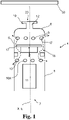
- Fig. 1 shows a part of an exemplary earpiece part 4 for an earpiece of a hearing device.
- the earpiece part 4 has an earpiece axis X_E.
- the earpiece axis X_E may be a longitudinal axis of the earpiece part 4 and/or of the earpiece.
- the earpiece part 4 comprises an earpiece housing 5 having a proximal end 6, a distal end 7, and an outer surface 8 connecting the distal end 7 to the proximal end 6.
- the proximal end 6 is the end closest to an ear drum 50 of the user when the earpiece 3 is inserted into the ear of the user.
- the distal end 7 is the end furthest away from the ear drum 50 of the user when the earpiece 3 is inserted into the ear of the user.
- the earpiece housing 5 comprises a first primary vent aperture 9, such as one or more first primary vent apertures 9, and a second primary vent aperture 10, such as one or more first primary vent apertures 10, in the outer surface 8.
- the first primary vent aperture 9 of the earpiece housing 5 is proximal to the second primary vent aperture 10 of the earpiece housing 5.
- the first primary vent aperture 9 is arranged closer to the ear drum 50 than the second primary vent aperture 10, when the earpiece 3 is arranged in the ear of a user.
- the one or more first primary vent aperture(s) 9 are arranged at first distance from the proximal end 6 of the earpiece housing 5 and the one or more second vent aperture(s) 10 are arranged at a second distance from the proximal end 6 of the earpiece housing 5.
- the second distance is larger than the first distance.
- the earpiece housing 5 has a sound outlet 20 at the proximal end 6 of the earpiece housing 5 and separate from the first vent apertures.
- the sound outlet 20 is in the example earpiece part 4 shown in Fig. 1 an aperture in the earpiece housing 5, such as in the proximal end of the earpiece housing 5.
- the sound outlet 20 is arranged in a nozzle 12 of the earpiece housing 5.
- the sound outlet 20 may have an outlet area, the outlet area having a normal.
- the normal of the outlet area of the sound outlet 20 is arranged parallel to a longitudinal axis of the earpiece part 4 and/or of the earpiece housing 5, such as parallel to the earpiece axis X_E.
- the example earpiece part 4 shown in Fig. 1 comprises a vent mechanism 18 arranged between the first primary vent aperture 9 and the second primary vent aperture 10 of the earpiece housing 5.
- the vent mechanism 18 may be configured to open and close the vent path 17 between the first primary vent aperture 9 and the second primary vent aperture 10.
- the vent mechanism 18 allows air to flow through the earpiece part 4, between a proximal end and a distal end of the earpiece 3.
- the vent mechanism 18 prevents air from flowing through the vent path 17 in the earpiece part 4, e.g., between a proximal end and a distal end of the earpiece part 4 and/or between a distal side and a proximal side of the vent mechanism 18.
- the vent mechanism 18 prevents the first primary vent aperture 9 and the second primary vent aperture 10 from being in fluid communication.
- the exemplary earpiece housing 5 shown in Fig, 1 comprises a flange 19 arranged at the proximal end 6 of the earpiece housing 5 for securely attaching a dome to the earpiece housing 5.
- the flange 19 is configured to mate with a corresponding groove for receiving the flange 19 in the dome.
- the flange 19 is configured to secure the dome to the earpiece housing 5 in a longitudinal direction of the earpiece housing 5.
- the flange 19 is arranged circumferentially along the outer surface 8 of the earpiece housing 5.
- the flange 19 is arranged along a section of the outer surface 8 of the earpiece housing 5.
- the flange 19 is arranged on the outer surface 8 at the proximal end of the earpiece housing 5.
- the flange 19 is arranged on the earpiece housing 5 so that, when a dome with a corresponding groove for receiving the flange 19 is arranged on the earpiece housing 5, the first primary vent aperture and/or the first vent groove of the dome is aligned and/or overlaps with the first primary vent aperture 9 of the earpiece housing 5 in a longitudinal direction of the earpiece housing 5.
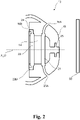
- Fig. 2 shows an exemplary dome 13 for an earpiece of a hearing device.
- the dome 13 is configured for securing the earpiece in the ear canal of the user.
- the dome has a dome axis X_D.
- the dome axis X_D may be a longitudinal axis of the dome 13.
- the dome 13 has an inner surface 14 configured to extend circumferentially along an outer surface of an earpiece housing of an earpiece housing part, such as along the outer surface 8 of the earpiece housing part 4 shown in Fig. 1 .
- the dome 13 comprises a proximal surface 15 having a first primary vent aperture 16A.
- the proximal surface 15 of the dome 13 is the surface of the dome 13 facing the ear drum 50 when the dome is arranged on an earpiece housing part and the earpiece is inserted into the ear canal of the user.
- the first primary vent aperture 16A of the dome 13 is configured to align with a first primary vent aperture in the earpiece housing when the dome 13 is arranged on the earpiece housing, so that a vent path forming a fluid communication between the first primary vent aperture 16A of the dome 13 and a first primary vent aperture of an earpiece housing is formed, such as the first primary vent aperture 9 of the earpiece housing 5 of the earpiece part 4 of Fig. 1 .
- the inner surface 14 of the dome 13 comprises a first vent groove 21 being in fluid communication with the first primary vent aperture 16A in the dome 13.
- the first primary vent aperture 16A is a throughgoing hole and/or a channel in the dome 13, extending from the proximal surface 15 of the dome 13 to the inner surface 14 of the dome 13.
- the first primary vent aperture allows air to flow between the proximal surface 15 of the dome 13 to the inner surface 14 of the dome 13.
- the first vent groove 21 is configured to be aligned with the first primary vent aperture in the earpiece housing along the longitudinal axis, such as along the earpiece housing axis X_EH.
- the first vent groove 21 is circumferentially arranged along the inner surface 14 of the dome 13.
- the first vent groove 21 has a first depth.
- the first vent groove 21 may extend fully or partly along the circumference of the inner surface 14.
- the first vent groove 21 extends perpendicular to the longitudinal axis, such as the dome axis X_D.
- the exemplary dome 13 further comprises secondary vent apertures 23.
- the proximal surface 15 of the dome 13 has a first secondary vent aperture 23A.
- the first secondary vent aperture 23A is in fluid communication with the first vent groove 21.
- the first secondary vent aperture 23A allows a fluid, such as air, to flow from the proximal side of the dome 13, such as from the proximal surface 15 of the dome 13 to the first vent groove 21 and/or from the first vent groove 21 to the proximal side of the dome 13.
- the exemplary dome 13 of Fig. 2 comprises a distal surface 24 having a second primary vent aperture 16B in the distal surface 24.
- the second primary vent aperture 16B in the dome 13 is configured to be in fluid communication with the second primary vent aperture in the earpiece housing when the dome 13 is arranged on the earpiece housing.
- the second primary vent aperture 16B is configured to allow a fluid, such as air, to flow from the second primary vent aperture in the earpiece housing to a distal side of the dome 13 or vice versa.
- the distal surface 24 further has a second secondary vent aperture 23B in the distal surface 24.
- the second secondary vent aperture 23B is configured to be in fluid communication with the second primary vent aperture in the earpiece housing when the dome 13 is arranged on the earpiece part 4.
- the inner surface 14 of the dome 13 comprises a second vent groove 22 being in fluid communication with the second primary vent aperture 16B of the dome 13.
- the second vent groove 22 is configured to be aligned with the second primary vent aperture 10 in the earpiece housing along the longitudinal axis, when the dome is arranged on the earpiece housing part.
- the second vent groove 22 is circumferentially arranged along the inner surface 14 of the dome 13.
- the second vent groove 22 is arranged distal to the first vent groove 21.
- the second vent groove 22 may have a second depth.
- the second depth may be the same or greater or smaller than the first depth of the first vent groove 21.
- the second vent groove 22 may extend fully or partly along the circumference of the inner surface 14 of the dome 13.
- the second vent groove 22 may extend perpendicular to the longitudinal axis, such as the dome axis X_D.
- the 3 further comprises a groove 25 for receiving a flange arranged at a proximal end of the earpiece housing for securing the dome 13 to the earpiece housing 5.
- the groove 25 is arranged circumferentially along the inner surface 14 of the dome 13.
- the groove is arranged on the inner surface 14 of the dome 13, such that when the dome 13 is arranged on the earpiece housing 13 and the flange is received in the groove 25, the first primary vent aperture 16A and/or the first vent groove 21 is correctly aligned and in fluid communication with the first primary vent aperture of the earpiece housing 5.
- an alignment of the dome 13 with the earpiece housing in an angular direction is not required to ensure fluid communication between the second primary vent apertures of the earpiece housing and the second primary vent aperture 16B in the dome 13. Thereby, a mounting and aligning of the dome 13 to the earpiece housing is facilitated.
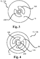
- Fig. 3 shows an exemplary dome 13 for an earpiece of a hearing device seen from a proximal side along a longitudinal axis of the dome 13.
- the dome 13 comprises a proximal surface 15 facing the eardrum of the user when the dome 13 is arranged on an earpiece housing and the earpiece is inserted into the ear canal of the user.
- the proximal surface 15 has a circular shape.
- the proximal surface 15 has the first primary vent aperture 16A and the first secondary vent aperture 23A.
- the first primary vent aperture 16A and the first secondary vent aperture 23A connect the proximal surface 15 with the inner surface 14 of the dome 13 for allowing fluid communication between the proximal surface 15 and the inner surface 14 of the dome 13.
- the first primary vent aperture 16A may be in fluid communication with the first vent groove (not shown in Fig. 3 ) being arranged circumferentially on the inner surface 14 of the dome 13.
- the first secondary vent aperture 23A may be in fluid communication with the first vent groove (not shown in Fig. 3 ) being arranged circumferentially on the inner surface 14 of the dome 13.
- the first primary vent aperture 16A and the first secondary vent aperture 23A are evenly distributed around the circumference of the dome, such as arranged at a 180-degree angle from each other.
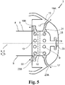
- Fig. 4 shows an exemplary dome 13 for an earpiece of a hearing device seen from a distal side along the longitudinal axis of the dome 13.
- the dome 13 has an inner surface 14 forming a cavity 14A.
- the inner surface 14 is configured for extending circumferentially along an outer surface of an earpiece housing, such as around the outer surface 8 of the exemplary earpiece housings 5, 5A, 5B or 5C shown in Fig. 1 and Fig. 7-9 .
- the cavity 14A is configured to accommodate at least a part of the earpiece housing, such as at least a part of the earpiece housing 5, 5A, 5B, 5C.
- the dome 13 comprises a distal surface 24 facing away from the ear drum 50 of the user when the dome 13 is arranged on an earpiece housing and the earpiece is inserted into the ear canal of the user.
- the distal surface 24 has a circular shape.
- the distal surface 24 has the second primary vent aperture 16B and the second secondary vent aperture 23B.
- the second primary vent aperture 16B and the first secondary vent aperture 23B connect the distal surface 24 with the inner surface 14 of the dome 13 for allowing fluid communication between the distal surface 24 and the inner surface 14 of the dome 13.
- the second primary vent aperture 16B can be in fluid communication with the second vent groove (not shown in Fig. 4 ) being arranged circumferentially on the inner surface 14 of the dome 13.
- the second secondary vent aperture 23B may be in fluid communication with the second vent groove (not shown in Fig. 4 ) being arranged circumferentially on the inner surface 14 of the dome 13.
- the second primary vent aperture 16B and the second secondary vent aperture 23B are evenly distributed around the circumference of the dome, such as arranged at a 180-degree angle from each other.
- Fig. 5 shows a part of an exemplary earpiece 3 for a hearing device.
- the earpiece 3 comprises an earpiece part 4 and a dome 13 in cross-section.
- the earpiece part 4 may be the earpiece part 4 shown in Fig. 1 and comprising an earpiece housing 5 having a distal end 6, a proximal end 7, and an outer surface 8 connecting the distal end 5 to the proximal end 6.
- the proximal end 6 can herein be seen as the end closest to an ear drum of the user when the earpiece 3 is inserted into the ear of the user.
- the distal end 7 can herein be seen as the end furthest away from an ear drum of the user when the earpiece 3 is inserted into the ear of the user.
- the earpiece housing 5 comprises a first primary vent aperture 9 and a second primary vent aperture 10 in the outer surface 8, such as in the outer surface of the earpiece housing.
- the first primary vent aperture 9 and the second primary vent aperture 10 allow fluid communication, such as air flow, through the outer surface 8 of the earpiece housing 5, such that air can enter or leave the earpiece housing 5 through the first primary vent aperture 9 and the second primary vent aperture 10.
- the first primary vent aperture 9 is arranged proximal to the second primary vent aperture 10.
- the earpiece part 4 comprises a receiver 11 arranged within the earpiece housing 5.
- the receiver 11 has a receiver axis X_R.
- the receiver axis X_R may be a longitudinal center axis of the receiver 11.
- the receiver 11 may comprise a receiver membrane.
- the receiver axis X_R may be perpendicular to a normal of the receiver membrane.
- the earpiece 3 comprises a dome 13 for securing the earpiece in the ear canal, such as the dome 13 shown in Figs. 2-4 .
- the dome 13 is arranged on the arranged on the proximal end 6 of the earpiece part 4.
- the dome 13 has an inner surface 14 extending circumferentially along the outer surface 8 of the earpiece housing 5.
- the dome 13 comprises a proximal surface 15 having a first primary vent aperture 16A and a first secondary vent aperture 23A.
- the earpiece 3 comprises a vent path 17 forming a fluid communication between the first primary vent aperture 16A and/or the first secondary vent aperture 23A of the dome 13 and the second primary vent aperture 10 of the earpiece housing 5 via the first primary vent aperture 9 of the earpiece housing 5.
- the vent path 17 allows air to flow through at least a part of the earpiece housing 5, such as from the proximal end 6 of the earpiece housing to a distal end 7 of the earpiece housing and/or from the distal end 7 of the earpiece housing to the proximal end 6 of the earpiece housing.
- the vent apertures in the dome 13 and in the earpiece part 4 form the vent path 17 of the earpiece 3.
- the vent path 17 is thus routed through or extends through both the dome 13 and the earpiece part 4. Air can thus flow from a proximal side of the earpiece 3 via the first primary vent aperture 16A and/or the first secondary vent aperture 23A in the dome 13, through at least a part of the earpiece housing 5 via the first primary vent aperture 9 and the second primary vent aperture 10 of the earpiece housing 4, to a distal side of the earpiece 3 via the second primary vent aperture 16B and/or the second secondary vent aperture 23B arranged in the distal surface 24 of the dome 13.
- the vent path 17 through the dome 13 via the first primary vent aperture 9, the dimensions of the proximal end of the earpiece housing 4, such as of the sound outlet of the earpiece housing, can be reduced.
- the size of the proximal end of the earpiece housing 4 facilitates insertion and withdrawal of the earpiece 3 from an ear of the user, e.g., by provision of an improved attachment of the dome 13 to the earpiece housing 4. Furthermore, the risk of the earpiece 3 and/or parts of the earpiece 3 getting stuck inside the ear can be reduced. Reducing, the size of the proximal end of the earpiece housing 4 also allows for an improved form factor of the earpiece 3 and/or the dome 13 which can increase the wearing comfort to a user of the earpiece 3.
- the inner surface 14 of the dome 13 comprises the first vent groove 21.
- the first vent groove 21 is in fluid communication with the first primary vent aperture 16A and the first secondary vent aperture 23A in the dome.
- the first vent groove 21 is aligned with, or at least overlaps with, and is in fluid communication with one or more first primary vent aperture(s) 9 in the earpiece housing 5 along the earpiece axis X_E.
- the first vent groove 21 is circumferentially arranged along the inner surface 14 of the dome 13.
- the inner surface 14 of the dome 13 further comprises the second vent groove 22 circumferentially arranged along the inner surface 14 of the dome 13.
- the second vent groove 22 is aligned and in fluid communication with the second primary vent aperture(s) 10 in the earpiece housing 5 along the earpiece housing axis X_EH.
- the second vent groove 22 is in fluid communication with the second primary vent aperture 16B and the second secondary vent aperture 23B in the dome and thus provides fluid communication between the distal surface 24 of the dome 13 and the second primary vent aperture 10 of the earpiece housing.
- the exemplary earpiece 3 shown in Fig. 5 comprises a vent mechanism 18 arranged in the earpiece housing 5.
- the vent mechanism 18 is arranged between the first primary vent aperture 9 and the second primary vent aperture 10 of the earpiece housing 5. And is configured to open and close the vent path 17.
- the earpiece housing 5 comprises the flange 19 arranged at the proximal end of the earpiece housing 5.
- the flange 19 is arranged in the corresponding groove 25 of the dome 13, so that the dome 13 is aligned with the earpiece housing 5.
- the first primary vent aperture 16A, the first secondary vent aperture 23A and/or the first vent groove 21 are aligned and in fluid communication with the first primary vent aperture 9 of the earpiece housing 5.
- the second primary vent aperture 16B, the second secondary vent aperture 23B and/or the second vent groove 21 are aligned and in fluid communication with the second primary vent aperture 10 of the earpiece housing 5.
- the flange 19 thus secures the dome 13 to the earpiece part 4 in an aligned position in the longitudinal direction of the earpiece 3.
- Fig. 6 shows a part of an exemplary earpiece 3A.
- the earpiece 3A comprises an exemplary earpiece housing 5A and an exemplary dome 13A.
- the outer surface 8 of the earpiece housing 5A comprises a first protrusion 31.
- the first protrusion 31 is aligned with the first vent groove 21 of the inner surface of the dome 13A along the longitudinal axis, such as along the earpiece axis X_E.
- the first vent groove 21 of the dome 13A receives the first protrusion 31 and thereby secures the dome 13A to the earpiece housing 5A in the longitudinal direction, such as along the earpiece axis X_E.
- the first protrusion 31 has a first height.
- the first height of the first protrusion 31 is less than the first depth of the first vent groove 21 in the dome 13A to ensure fluid communication via the first vent groove 21 in the dome 13A.
- the first protrusion 31 is circumferentially arranged along the outer surface 8 of the earpiece housing 5A.
- the first protrusion 31 may extend fully or partly along the circumference of the outer surface 8.
- the first protrusion 31 extends perpendicular to the earpiece axis X_E.
- the first protrusion 31 may comprise a plurality of first protrusion parts arranged along the circumference of the outer surface in the first position.
- the first vent aperture(s) 9 of the earpiece housing 5A is formed in the first protrusion 31.
- the outer surface 8 of the exemplary earpiece housing 5A comprises a second protrusion 32.
- the second protrusion 32 is aligned with the second vent groove 22 of the inner surface of the dome 13A along the earpiece axis X_E.
- the second vent groove 22 of the dome 13A receives the second protrusion 32 and thereby secures the dome 13A to the earpiece housing 5A in the longitudinal direction, such as along the earpiece axis X_E.
- the second protrusion 32 has a second height.
- the second height of the second protrusion 32 is less than the second depth of the second vent groove 22 in the dome 13A to ensure fluid communication via the second vent groove 22 in the dome 13A.
- a cavity is provided between the outer surface of the second protrusion 32 and the inner surface of the second vent groove 22 of the dome 13A through which a fluid can flow.
- the second protrusion 32 is circumferentially arranged along the outer surface 8 of the earpiece housing 5A.
- the second protrusion 32 may extend fully or partly along the circumference of the outer surface 8.
- the second protrusion 32 extends perpendicular to the earpiece axis X_E.
- the dome 13A may be further secured to the earpiece housing 5A.
- the second protrusion 32 may comprise a plurality of second protrusion parts arranged along the circumference of the outer surface 8 in the second position. In the example earpiece housing 5A shown in Fig. 6 , the second vent aperture(s) 10 of the earpiece housing 5A is formed in the second protrusion 32.
- the first primary vent aperture 16A and the first secondary vent aperture 23A in the exemplary dome 13A are arranged parallel to the dome axis X_D.
- the second primary vent aperture 16B and the second secondary vent aperture 23B in the exemplary dome 13A are arranged parallel to the dome axis X_D.
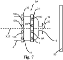
- Fig. 7 shows an exemplary earpiece housing 5A.
- the exemplary earpiece housing 5A comprises the first protrusion 31 arranged on the outer surface 8 of the earpiece housing 5A and the second protrusion 32 arranged on the outer surface 8 of the earpiece housing 5A.
- the first protrusion 31 is arranged proximal to the second protrusion 32.
- the first protrusion 31 is configured to be aligned with the first vent groove 21 of the inner surface of the dome 13A along the longitudinal axis, such as along the earpiece axis X_E, when the dome is mounted to the earpiece housing 5A.
- the first protrusion 31 has a first height.
- the first height of the first protrusion 31 is less than a first depth of the first vent groove 21 in the dome 13A to ensure fluid communication via the first vent groove 21 in the dome 13A, when the dome 13A is mounted on the earpiece housing 5A.
- the first protrusion 31 is circumferentially arranged along the outer surface 8 of the earpiece housing 5A.
- the first protrusion 31 may extend fully or partly along the circumference of the outer surface 8.
- the first protrusion 31 extends perpendicular to the earpiece axis X_E.
- the second protrusion 32 is configured to be aligned with the second vent groove 22 of the inner surface of the dome 13A along the longitudinal axis, such as along the earpiece axis X_E, when the dome is mounted to the earpiece housing 5A.
- the second protrusion 32 has a second height.
- the second height of the second protrusion 32 is less than the second depth of the second vent groove 22 in the dome 13A to ensure fluid communication via the second vent groove 22 in the dome 13A.
- the second protrusion 32 is circumferentially arranged along the outer surface 8 of the earpiece housing 5A.
- the second protrusion 32 may extend fully or partly along the circumference of the outer surface 8.
- the second protrusion 32 extends perpendicular to the earpiece axis X_E.
- a plurality of first vent apertures such as a first primary vent aperture 9, a first secondary vent aperture 9A, a first tertiary vent aperture 9B, a first quaternary vent aperture 9C, are formed in the first protrusion 31.
- the first primary vent aperture 9, the first secondary vent aperture 9A, the first tertiary vent aperture 9B and/or the first quaternary vent aperture 9C are arranged around the circumference of the first protrusion 31 and are configured to be in fluid communication with the first vent groove 21 of the dome 13, 13A.
- a plurality of second vent apertures such as the second primary vent aperture 10, the second secondary vent aperture 10A, the second tertiary vent aperture 10B and/or the second quaternary vent aperture 10C, are formed in the first protrusion 31.
- the second primary vent aperture 10, the second secondary vent aperture 10A, the second tertiary vent aperture 10B and/or the second quaternary vent aperture 10C are arranged around the circumference of the second protrusion 32 and are configured to be in fluid communication with the second vent groove 22 of the dome 13, 13A.
- Fig. 8 shows an exemplary earpiece housing 5B.
- the exemplary earpiece housing 5B comprises the first protrusion 31 arranged on the outer surface 8 of the earpiece housing 5B.
- the first protrusion 31 is arranged on a proximal end of the earpiece housing 5B.
- the first protrusion 31 is configured to be aligned with the first vent groove 21 of the inner surface 14 of the dome 13, 13A along the longitudinal axis, such as along the earpiece axis X_E, when the dome 13, 13A is mounted to the earpiece housing 5B.
- the first protrusion 31 has a first height.
- the first height of the first protrusion 31 is less than a first depth of the first vent groove 21 in the dome 13, 13A to ensure fluid communication via the first vent groove 21 in the dome 13, 13A, when the dome 13, 13A is mounted on the earpiece housing 5B.
- the first protrusion 31 is circumferentially arranged along the outer surface 8 of the earpiece housing 5B.
- the plurality of first vent apertures such as the first primary vent aperture 9, the first secondary vent aperture 9A, the first tertiary vent aperture 9B and/or the first quaternary vent aperture 9C, are formed in the first protrusion 31.
- the plurality of second vent apertures are formed in the outer surface 8 of the earpiece housing 5B.
- the second primary vent aperture 10, the second secondary vent aperture 10A, the second tertiary vent aperture 10B and/or the second quaternary vent aperture 10C are arranged on the outer surface 8 of the earpiece housing 5B, such as around the circumference of the outer surface 8 of the earpiece housing 5B.
- the second primary vent aperture 10, the second secondary vent aperture 10A, the second tertiary vent aperture 10B and/or the second quaternary vent aperture 10C are configured to be aligned with the second vent groove 22 of the inner surface 14 of the dome 13, 13A along the longitudinal axis, such as along the earpiece axis X_E, when the dome 13, 13A is mounted to the earpiece housing 5B.
- the second primary vent aperture 10, the second secondary vent aperture 10A, the second tertiary vent aperture 10B and/or the second quaternary vent aperture 10C are configured to be in fluid communication with the second vent groove 22 of the dome 13, 13A.
- Fig. 9 shows an exemplary earpiece housing 5C.
- the exemplary earpiece housing 5C comprises the second protrusion 32 arranged on the outer surface 8 of the earpiece housing 5C.
- the second protrusion 32 is arranged on a distal end of the earpiece housing 5C.
- the second protrusion 32 is configured to be aligned with the second vent groove 22 of the inner surface 14 of the dome 13, 13A along the longitudinal axis, such as along the earpiece axis X_E, when the dome 13, 13A is mounted to the earpiece housing 5C.
- the second protrusion 32 can thus be received by the second vent groove 22 of the dome 13, 13A, when the dome 13, 13A is mounted on the earpiece housing 5C.
- the second protrusion 32 has a second height.
- the second height of the second protrusion 32 is less than a second depth of the second vent groove 22 in the dome 13, 13A to ensure fluid communication via the second vent groove 22 in the dome 13, 13A, when the dome 13, 13A is mounted to the earpiece housing 5C.
- the second protrusion 32 is circumferentially arranged along the outer surface 8 of the earpiece housing 5C.
- the plurality of second vent apertures such as the second primary vent aperture 10, the second secondary vent aperture 10A, the second tertiary vent aperture 10B and/or the second quaternary vent aperture 10C, are formed in the second protrusion 32.
- the plurality of second vent apertures are formed in an outer surface of the protrusion 32.
- the second primary vent aperture 10, the second secondary vent aperture 10A, the second tertiary vent aperture 10B and/or the second quaternary vent aperture 10C are configured to be aligned with the second vent groove 22 of the inner surface 14 of the dome 13, 13A along the longitudinal axis, such as along the earpiece axis X_E, when the dome 13, 13A is mounted to the earpiece housing 5C.
- the plurality of first vent apertures are arranged on the outer surface 8 of the earpiece housing 5C.
- the first primary vent aperture 9, the first secondary vent aperture 9A, the first tertiary vent aperture 9B and/or the first quaternary vent aperture 9C are configured to be aligned with the second vent groove 22 of the inner surface 14 of the dome 13, 13A along the longitudinal axis, such as along the earpiece axis X_E, when the dome 13, 13A is mounted to the earpiece housing 5C.
- the first primary vent aperture 9, the first secondary vent aperture 9A, the first tertiary vent aperture 9B, and/or the first quaternary vent aperture 9C are distributed around the circumference of the outer surface 8 of the earpiece housing 5C.
- the first primary vent aperture 9, the first secondary vent aperture 9A, the first tertiary vent aperture 9B and/or the first quaternary vent aperture 9C are configured to be in fluid communication with the first vent groove 21 of the dome 13, 13A.
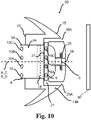
- Fig. 10 shows a part of an exemplary earpiece 3B.
- the earpiece 3B comprises an exemplary earpiece housing 5A and an exemplary dome 13B.
- the outer surface 8 of the earpiece housing 5A comprises a first protrusion 31.
- the inner surface 14 of the dome 13 comprises a single vent groove, such as the first vent groove 21, being in fluid communication with the first primary vent aperture 16A in the dome 13.
- the exemplary dome 13B does, in contrast to the exemplary dome 13A of Fig. 6 , not comprise a second vent groove in the distal end of the dome 13B.
- the first vent groove 21 is further in fluid communication with a first secondary vent aperture 23A.
- the first primary vent aperture 16A and/or the first secondary vent aperture is a through-going hole and/or a channel in the dome 13B, extending from the proximal surface 15 of the dome 13 to the inner surface 14 of the dome 13B.
- the first primary vent aperture 16A allows air to flow between the proximal surface 15 of the dome 13B to the inner surface 14 of the dome 13B.
- the first vent groove 21 is configured to be aligned with the first primary vent aperture 9 in the earpiece housing 5A along the longitudinal axis, such as along the earpiece axis X_E.
- the first vent groove 21 is circumferentially arranged along the inner surface 14 of the dome 13B.
- the first vent groove 21 has a first depth.
- the first vent groove 21 may extend fully or partly along the circumference of the inner surface 14.
- the first vent groove 21 extends perpendicular to the longitudinal axis, such as the dome axis X_D.
- the first protrusion 31 of the earpiece housing 5A is aligned with the first vent groove 21 of the inner surface of the dome 13A along the longitudinal axis, such as along the earpiece axis X_E.
- the first vent groove 21 of the dome 13A receives the first protrusion 31 and thereby secures the dome 13A to the earpiece housing 5A in the longitudinal direction, such as along the earpiece axis X_E.
- the first protrusion 31 has a first height. The first height of the first protrusion 31 is less than the first depth of the first vent groove 21 in the dome 13A to ensure fluid communication via the first vent groove 21 in the dome 13A.
- the first height of the first protrusion 31 being less than the first depth of the first vent groove 21 in the dome 13A a cavity is provided between the outer surface of the first protrusion 31 and an inner surface of the first vent groove 21 of the dome 13A through which a fluid can flow.
- the first protrusion 31 is circumferentially arranged along the outer surface 8 of the earpiece housing 5A.
- the first protrusion 31 may extend fully or partly along the circumference of the outer surface 8.
- the first protrusion 31 extends perpendicular to the earpiece axis X_E.
- the first protrusion 31 may comprise a plurality of first protrusion parts arranged along the circumference of the outer surface in the first position.
- the first vent aperture(s) 9 of the earpiece housing 5A is formed in the first protrusion 31.
- the example earpiece housing 5A comprises a second vent aperture 10 arranged distal to the first vent apertures 9.
- the second vent apertures 10 are arranged distal to the distal surface 24 of the dome 13B, when the dome 13B is arranged on the earpiece housing 5A. in the exemplary earpiece 3B shown in Fig.
- the distal surface 24 of the dome 13B is thus arranged proximal to the second vent aperture 10 of the earpiece hosing 5A along the earpiece axis X_E.
- the second vent apertures 10 are thus in fluid communication with an outer ear canal, such that air can flow between the earpiece housing 5A and the outer ear canal, through the second vent apertures 10 without passing through the dome 13B.
- earpieces for hearing devices examples include earpiece parts, earpiece parts and domes according to the disclosure are set out in the following items:
- Figs. 1-9 comprise some modules or operations which are illustrated with a solid line and some modules or operations which are illustrated with a dashed line.
- the modules or operations which are comprised in a solid line are modules or operations which are comprised in the broadest example embodiment.
- the modules or operations which are comprised in a dashed line are example embodiments which may be comprised in, or a part of, or are further modules or operations which may be taken in addition to the modules or operations of the solid line example embodiments. It should be appreciated that these operations need not be performed in order presented. Furthermore, it should be appreciated that not all of the operations need to be performed.
- the exemplary operations may be performed in any order and in any combination.
Applications Claiming Priority (1)
| Application Number | Priority Date | Filing Date | Title |
|---|---|---|---|
| DKPA202070805A DK202070805A1 (en) | 2020-11-30 | 2020-11-30 | Earpiece for a hearing device, dome and earpiece part |
Publications (1)
| Publication Number | Publication Date |
|---|---|
| EP4007304A1 true EP4007304A1 (de) | 2022-06-01 |
Family
ID=78676458
Family Applications (1)
| Application Number | Title | Priority Date | Filing Date |
|---|---|---|---|
| EP21208724.1A Pending EP4007304A1 (de) | 2020-11-30 | 2021-11-17 | Ohrstück für ein hörgerät, kuppel und ohrstückteil |
Country Status (5)
| Country | Link |
|---|---|
| US (1) | US11956596B2 (de) |
| EP (1) | EP4007304A1 (de) |
| JP (1) | JP2022087060A (de) |
| CN (1) | CN114640916A (de) |
| DK (1) | DK202070805A1 (de) |
Families Citing this family (1)
| Publication number | Priority date | Publication date | Assignee | Title |
|---|---|---|---|---|
| US11553284B2 (en) * | 2020-11-11 | 2023-01-10 | Gn Hearing A/S | Detection of filter clogging for hearing devices |
Citations (4)
| Publication number | Priority date | Publication date | Assignee | Title |
|---|---|---|---|---|
| WO2019052715A1 (en) * | 2017-09-18 | 2019-03-21 | Sonova Ag | COMMUNICATION DEVICE COMPRISING AN ACOUSTIC JOINT AND VENT OPENING |
| EP3675524A1 (de) * | 2018-12-28 | 2020-07-01 | GN Hearing A/S | Verfahren zur bestimmung eines zustands eines pfads von akustischem feedback eines am kopf tragbaren hörgeräts sowie am kopf tragbares hörgerät |
| EP3716649A1 (de) * | 2019-03-27 | 2020-09-30 | Sonova AG | Hörgerät mit einer entlüftung mit einem verstellbaren akustischen ventil |
| EP3726855A1 (de) * | 2019-04-15 | 2020-10-21 | Sonion Nederland B.V. | Persönliches hörgerät mit entlüftungskanal und akustischer trennung |
Family Cites Families (10)
| Publication number | Priority date | Publication date | Assignee | Title |
|---|---|---|---|---|
| US8457336B2 (en) * | 2004-02-05 | 2013-06-04 | Insound Medical, Inc. | Contamination resistant ports for hearing devices |
| US7551747B2 (en) * | 2004-02-13 | 2009-06-23 | Insound Medical, Inc. | Perforated cap for a hearing aid |
| JP5914887B2 (ja) | 2011-07-22 | 2016-05-11 | パナソニックIpマネジメント株式会社 | イヤホン |
| US8820474B2 (en) | 2011-08-25 | 2014-09-02 | Magnatone Hearing Aid Corporation | Ear tip piece for hearing instruments |
| EP2819435A1 (de) | 2013-06-26 | 2014-12-31 | Oticon A/s | Belüftete Kuppel |
| EP2849461B1 (de) * | 2013-09-16 | 2017-08-30 | Oticon A/s | Filterelement |
| EP4344253A2 (de) * | 2018-12-14 | 2024-03-27 | GN Hearing A/S | Ohrplastik mit verschlusselement für entlüftung |
| EP3706440A1 (de) | 2019-03-08 | 2020-09-09 | GN Hearing A/S | Hörgerät mit entlüftung |
| US11570537B2 (en) * | 2020-08-31 | 2023-01-31 | Oticon A/S | Dome for hearing aids |
| DK181159B1 (en) * | 2020-11-30 | 2023-03-09 | Gn Hearing As | Hearing device earpiece and receiver with vent assembly |
-
2020
- 2020-11-30 DK DKPA202070805A patent/DK202070805A1/en not_active Application Discontinuation
-
2021
- 2021-11-10 US US17/523,547 patent/US11956596B2/en active Active
- 2021-11-17 EP EP21208724.1A patent/EP4007304A1/de active Pending
- 2021-11-26 JP JP2021192549A patent/JP2022087060A/ja active Pending
- 2021-11-30 CN CN202111440408.7A patent/CN114640916A/zh active Pending
Patent Citations (4)
| Publication number | Priority date | Publication date | Assignee | Title |
|---|---|---|---|---|
| WO2019052715A1 (en) * | 2017-09-18 | 2019-03-21 | Sonova Ag | COMMUNICATION DEVICE COMPRISING AN ACOUSTIC JOINT AND VENT OPENING |
| EP3675524A1 (de) * | 2018-12-28 | 2020-07-01 | GN Hearing A/S | Verfahren zur bestimmung eines zustands eines pfads von akustischem feedback eines am kopf tragbaren hörgeräts sowie am kopf tragbares hörgerät |
| EP3716649A1 (de) * | 2019-03-27 | 2020-09-30 | Sonova AG | Hörgerät mit einer entlüftung mit einem verstellbaren akustischen ventil |
| EP3726855A1 (de) * | 2019-04-15 | 2020-10-21 | Sonion Nederland B.V. | Persönliches hörgerät mit entlüftungskanal und akustischer trennung |
Also Published As
| Publication number | Publication date |
|---|---|
| CN114640916A (zh) | 2022-06-17 |
| US11956596B2 (en) | 2024-04-09 |
| JP2022087060A (ja) | 2022-06-09 |
| US20220174431A1 (en) | 2022-06-02 |
| DK202070805A1 (en) | 2022-06-10 |
Similar Documents
| Publication | Publication Date | Title |
|---|---|---|
| EP3422734B1 (de) | Geflanschter ohrhörer und hörgerät damit | |
| US9467787B2 (en) | Hearing aid with a replaceable insertion cap | |
| US20110116668A1 (en) | Universal-fit hearing device | |
| US11882408B2 (en) | Earpiece with canal microphone, ambient microphone and receiver | |
| EP2025202B1 (de) | Universell passendes hörgerät | |
| US11956596B2 (en) | Earpiece for a hearing device, dome and earpiece part | |
| US20220174435A1 (en) | Hearing device earpiece and receiver with vent assembly | |
| US20230300548A1 (en) | Hearing device and earpiece with active vent | |
| US20220174438A1 (en) | Hearing device earpiece with tilted microphone/receiver | |
| US20230362562A1 (en) | Hearing device | |
| EP4254980A1 (de) | Hörvorrichtung | |
| US20230319494A1 (en) | Hearing device | |
| US11770652B2 (en) | Hearing device earpiece having intermediate module | |
| EP4254984A1 (de) | Hörgerät | |
| EP4254985A1 (de) | Hörgerät | |
| US20230319495A1 (en) | Hearing device | |
| US11019436B2 (en) | Earpiece for a hearing device and a hearing device |
Legal Events
| Date | Code | Title | Description |
|---|---|---|---|
| PUAI | Public reference made under article 153(3) epc to a published international application that has entered the european phase |
Free format text: ORIGINAL CODE: 0009012 |
|
| STAA | Information on the status of an ep patent application or granted ep patent |
Free format text: STATUS: THE APPLICATION HAS BEEN PUBLISHED |
|
| AK | Designated contracting states |
Kind code of ref document: A1 Designated state(s): AL AT BE BG CH CY CZ DE DK EE ES FI FR GB GR HR HU IE IS IT LI LT LU LV MC MK MT NL NO PL PT RO RS SE SI SK SM TR |
|
| STAA | Information on the status of an ep patent application or granted ep patent |
Free format text: STATUS: REQUEST FOR EXAMINATION WAS MADE |
|
| 17P | Request for examination filed |
Effective date: 20221130 |
|
| RBV | Designated contracting states (corrected) |
Designated state(s): AL AT BE BG CH CY CZ DE DK EE ES FI FR GB GR HR HU IE IS IT LI LT LU LV MC MK MT NL NO PL PT RO RS SE SI SK SM TR |
|
| GRAP | Despatch of communication of intention to grant a patent |
Free format text: ORIGINAL CODE: EPIDOSNIGR1 |
|
| STAA | Information on the status of an ep patent application or granted ep patent |
Free format text: STATUS: GRANT OF PATENT IS INTENDED |