EP4007128B1 - Motor and washing machine - Google Patents
Motor and washing machine Download PDFInfo
- Publication number
- EP4007128B1 EP4007128B1 EP20950480.2A EP20950480A EP4007128B1 EP 4007128 B1 EP4007128 B1 EP 4007128B1 EP 20950480 A EP20950480 A EP 20950480A EP 4007128 B1 EP4007128 B1 EP 4007128B1
- Authority
- EP
- European Patent Office
- Prior art keywords
- cover
- controller
- electromotor
- mounting part
- end cover
- Prior art date
- Legal status (The legal status is an assumption and is not a legal conclusion. Google has not performed a legal analysis and makes no representation as to the accuracy of the status listed.)
- Active
Links
Images



Classifications
-
- H—ELECTRICITY
- H02—GENERATION; CONVERSION OR DISTRIBUTION OF ELECTRIC POWER
- H02K—DYNAMO-ELECTRIC MACHINES
- H02K1/00—Details of the magnetic circuit
- H02K1/06—Details of the magnetic circuit characterised by the shape, form or construction
- H02K1/12—Stationary parts of the magnetic circuit
- H02K1/18—Means for mounting or fastening magnetic stationary parts on to, or to, the stator structures
- H02K1/185—Means for mounting or fastening magnetic stationary parts on to, or to, the stator structures to outer stators
-
- H—ELECTRICITY
- H02—GENERATION; CONVERSION OR DISTRIBUTION OF ELECTRIC POWER
- H02K—DYNAMO-ELECTRIC MACHINES
- H02K5/00—Casings; Enclosures; Supports
- H02K5/04—Casings or enclosures characterised by the shape, form or construction thereof
-
- D—TEXTILES; PAPER
- D06—TREATMENT OF TEXTILES OR THE LIKE; LAUNDERING; FLEXIBLE MATERIALS NOT OTHERWISE PROVIDED FOR
- D06F—LAUNDERING, DRYING, IRONING, PRESSING OR FOLDING TEXTILE ARTICLES
- D06F37/00—Details specific to washing machines covered by groups D06F21/00 - D06F25/00
- D06F37/20—Mountings, e.g. resilient mountings, for the rotary receptacle, motor, tub or casing; Preventing or damping vibrations
- D06F37/206—Mounting of motor
-
- H—ELECTRICITY
- H02—GENERATION; CONVERSION OR DISTRIBUTION OF ELECTRIC POWER
- H02K—DYNAMO-ELECTRIC MACHINES
- H02K1/00—Details of the magnetic circuit
- H02K1/06—Details of the magnetic circuit characterised by the shape, form or construction
- H02K1/12—Stationary parts of the magnetic circuit
-
- H—ELECTRICITY
- H02—GENERATION; CONVERSION OR DISTRIBUTION OF ELECTRIC POWER
- H02K—DYNAMO-ELECTRIC MACHINES
- H02K1/00—Details of the magnetic circuit
- H02K1/06—Details of the magnetic circuit characterised by the shape, form or construction
- H02K1/22—Rotating parts of the magnetic circuit
-
- H—ELECTRICITY
- H02—GENERATION; CONVERSION OR DISTRIBUTION OF ELECTRIC POWER
- H02K—DYNAMO-ELECTRIC MACHINES
- H02K11/00—Structural association of dynamo-electric machines with electric components or with devices for shielding, monitoring or protection
- H02K11/30—Structural association with control circuits or drive circuits
-
- H—ELECTRICITY
- H02—GENERATION; CONVERSION OR DISTRIBUTION OF ELECTRIC POWER
- H02K—DYNAMO-ELECTRIC MACHINES
- H02K5/00—Casings; Enclosures; Supports
- H02K5/02—Casings or enclosures characterised by the material thereof
-
- H—ELECTRICITY
- H02—GENERATION; CONVERSION OR DISTRIBUTION OF ELECTRIC POWER
- H02K—DYNAMO-ELECTRIC MACHINES
- H02K5/00—Casings; Enclosures; Supports
- H02K5/04—Casings or enclosures characterised by the shape, form or construction thereof
- H02K5/15—Mounting arrangements for bearing-shields or end plates
-
- H—ELECTRICITY
- H02—GENERATION; CONVERSION OR DISTRIBUTION OF ELECTRIC POWER
- H02K—DYNAMO-ELECTRIC MACHINES
- H02K5/00—Casings; Enclosures; Supports
- H02K5/04—Casings or enclosures characterised by the shape, form or construction thereof
- H02K5/16—Means for supporting bearings, e.g. insulating supports or means for fitting bearings in the bearing-shields
- H02K5/161—Means for supporting bearings, e.g. insulating supports or means for fitting bearings in the bearing-shields radially supporting the rotary shaft at both ends of the rotor
-
- H—ELECTRICITY
- H02—GENERATION; CONVERSION OR DISTRIBUTION OF ELECTRIC POWER
- H02K—DYNAMO-ELECTRIC MACHINES
- H02K5/00—Casings; Enclosures; Supports
- H02K5/04—Casings or enclosures characterised by the shape, form or construction thereof
- H02K5/18—Casings or enclosures characterised by the shape, form or construction thereof with ribs or fins for improving heat transfer
-
- H—ELECTRICITY
- H02—GENERATION; CONVERSION OR DISTRIBUTION OF ELECTRIC POWER
- H02K—DYNAMO-ELECTRIC MACHINES
- H02K7/00—Arrangements for handling mechanical energy structurally associated with dynamo-electric machines, e.g. structural association with mechanical driving motors or auxiliary dynamo-electric machines
- H02K7/08—Structural association with bearings
- H02K7/083—Structural association with bearings radially supporting the rotary shaft at both ends of the rotor
-
- H—ELECTRICITY
- H02—GENERATION; CONVERSION OR DISTRIBUTION OF ELECTRIC POWER
- H02K—DYNAMO-ELECTRIC MACHINES
- H02K7/00—Arrangements for handling mechanical energy structurally associated with dynamo-electric machines, e.g. structural association with mechanical driving motors or auxiliary dynamo-electric machines
- H02K7/14—Structural association with mechanical loads, e.g. with hand-held machine tools or fans
-
- D—TEXTILES; PAPER
- D06—TREATMENT OF TEXTILES OR THE LIKE; LAUNDERING; FLEXIBLE MATERIALS NOT OTHERWISE PROVIDED FOR
- D06F—LAUNDERING, DRYING, IRONING, PRESSING OR FOLDING TEXTILE ARTICLES
- D06F37/00—Details specific to washing machines covered by groups D06F21/00 - D06F25/00
- D06F37/30—Driving arrangements
- D06F37/304—Arrangements or adaptations of electric motors
-
- H—ELECTRICITY
- H02—GENERATION; CONVERSION OR DISTRIBUTION OF ELECTRIC POWER
- H02K—DYNAMO-ELECTRIC MACHINES
- H02K5/00—Casings; Enclosures; Supports
- H02K5/04—Casings or enclosures characterised by the shape, form or construction thereof
- H02K5/06—Cast metal casings
-
- H—ELECTRICITY
- H02—GENERATION; CONVERSION OR DISTRIBUTION OF ELECTRIC POWER
- H02K—DYNAMO-ELECTRIC MACHINES
- H02K5/00—Casings; Enclosures; Supports
- H02K5/04—Casings or enclosures characterised by the shape, form or construction thereof
- H02K5/08—Insulating casings
Definitions
- the present application relates to the technical field of household appliances, and particularly relates to an electromotor and a laundry machine.
- the invention of the laundry machine liberates people's hands.
- the laundry machine is an essential electric appliance in people's daily life.
- a controller arranged inside the laundry machine controls an electromotor to rotate so as to simulate a washing action.
- the controller is arranged on the electromotor; moreover, since the electromotor needs to be arranged on an external structure such as a water container of the laundry machine, so that a housing of the electromotor needs to be provided with a mounting structure arranged to be secured with the water container, thus, complex structures of end covers of the electromotor are caused, a range of selection of materials is restrained, resulting in a high cost.
- US2010/019629A1 relates to a brushless motor for a washing machine having a drive circuit accommodated in case. relates to a rotor type motor and discloses a control unit disposed in a housing.
- An objective of the embodiments of the present application is providing an electromotor and a laundry machine, which aims at solving a problem that the housing of the electromotor is provided with a structure fixedly connected with the water container, so that complex structures of the end covers of the electromotor are caused.
- an electromotor for a laundry machine includes a controller and a controller cover, the controller is arranged on the controller cover; the electromotor further includes a first end cover and a second end cover which is secured with the first end cover; the first end cover and the second end cover are fixed on two opposite sides of a stator respectively; the controller cover is provided with a first mounting part configured to be secured with the first end cover and is provided with a second mounting part configured to be secured with a water container of the laundry machine, and the first end cover is provided with a third mounting part configured to be secured with the first mounting part.
- the second mounting part is arranged on one side of the controller cover opposite to the controller.
- a surface of the controller cover protrudes outwards to form a mounting foot
- the second mounting part is arranged on the mounting foot
- the second mounting part is a mounting hole or a mounting column.
- a surface of the controller cover is provided with heat dissipation fins.
- the controller cover is the one selected from a group consisting of an aluminum cover, a cover made of aluminum alloy and a resin cover.
- the first mounting part and the third mounting part are connected by a fixing member, and the fixing member is arranged to pass through the first mounting part and the third mounting part.
- one side of the first end cover which faces towards the controller cover is provided with a first positioning element, and the controller cover is provided with a second positioning element that comes into engagement with the first positioning element; or one side of the stator which faces towards the controller cover is provided with a first positioning element, and the controller cover is provided with a second positioning element that comes into engagement with the first positioning element.
- the third mounting part is the first positioning element, and the first mounting part is the second positioning element; the first positioning element is provided with a first connecting hole, the second positioning element is provided with a second connecting hole, and the fixing member is arranged to pass through the first connecting hole and the second connecting hole.
- the controller is configured to be snap-fitted into the controller cover or the first end cover; or alternatively the controller is fixed with the controller cover or the first end cover through a fixing member.
- the first end cover is molded through a stretching molding, a casting molding, or an injection molding.
- the first end cover is a housing made of metal or a housing made of resin.
- the electromotor further includes the stator and a rotor configured to rotate relative to the stator, the rotor includes a rotating shaft and two bearings arranged at two ends of the rotating shaft respectively, the first end cover and the second end cover protrude outwards to form annular bosses, interiors of the annular bosses are provided with bearing bores for accommodating the bearings respectively, a bottom of at least one of the two annular bosses is provided with a groove structure or a convex structure.
- At least one of the first end cover and the second end cover is provided with an edge flanging which comes into contact with the stator tightly.
- the groove structure is an annular groove or the groove structure includes a plurality of separately arranged concave ribs which are enclosed to be ring-shaped;
- the convex structure is an annular boss or the convex structure includes a plurality of separately arranged convex ribs which are enclosed to be ring-shaped.
- a laundry machine in the second aspect, includes the electromotor described above and a water container.
- the electromotor disclosed in the embodiments of the present application has the beneficial effects as follows: the electromotor of the present application includes the first end cover, the second end cover, the controller and the controller cover, the controller is arranged on the controller cover, the controller cover is fixed through an engagement between the first mounting part arranged on the controller cover and the third mounting part arranged on the first end cover or the stator, so that the controller cover is enabled to be fixed on the housing or the stator; furthermore, the controller cover is secured with the water container of the laundry machine through the second mounting part arranged on the controller cover, in this way, it only needs to arrange the third mounting part secured with the controller cover on the housing of the electromotor, without the need of additionally arranging another mounting structure secured with the water container of the laundry machine on the first end cover, thereby effectively simplifying the structure of the first end cover, and reducing the cost of the laundry machine.
- the laundry machine disclosed in the embodiments of the present application has the beneficial effects listed below: the electromotor is applied in the laundry machine of the present application, the housing of the electromotor only needs to be provided with the third mounting part secured with the controller cover, without the need of additionally arranging another mounting structure secured with the water container of the laundry machine on the first end cover, thereby effectively simplifying the structure of the first end cover, and reducing the cost of the laundry machine.
- the electromotor 1 includes a housing 11, a controller 2 and a controller cover 3, the controller 2 may be configured to control the rotor 13 and other electronically controlled devices of the laundry machine.
- the controller 2 is arranged inside or outside the controller cover 3, and the controller cover 3 is fixed on the housing 11 of the electromotor 1 or a stator 12 of the electromotor 1.
- the housing 11 includes a first end cover 111 and a second end cover 112, the first end cover 111 and the second end cover 112 are fixed on two opposite sides of the stator 12, respectively.
- the controller cover 3 is provided with a first mounting part 31 and a second mounting part 320, the first end cover 111 or the stator 12 is provided with a third mounting part 1111, the first mounting part 31 and the third mounting part 1111 are arranged to be engaged with each other, so that the controller cover 3 is enabled to be fixed on the first end cover 111 or the stator 12, and the controller 2 is enabled to be integrated in the electromotor 1.
- the second mounting part 320 is configured to be connected with a water container 4 of the laundry machine, so that a structure which is originally arranged on the housing 11 of the electromotor 1 is redesigned to be arranged on the controller cover 3, thereby simplifying the structure of the housing 11 of the electromotor 1.
- the housing 11 of the electromotor 1 needs to support the rotor 13, if the structure of the housing 11 of the electromotor 1 is too complex, a difficulty in manufacturing the laundry machine may be increased, in order to ensure the strength of the housing 11 of the electromotor 1, the material and the production process of the housing 11 of the electromotor 1 are greatly limited.
- the housing 11 of the electromotor 1 in this embodiment is only provided with a third mounting part 1111, so that the complexity of the structure of the first end cover 111 is greatly reduced, the ranges of selections of the material and the production process of the first end cover 111 are broadened, and the production cost of the electromotor 1 is effectively reduced.
- the first end cover 111 in FIG. 3 is manufactured and molded by using a casting process; since the first end cover 111 has a simple structure, the first end cover 111 can be manufactured and molded by using different processes according to the requirement, and the requirement on the manufacturing process of the first end cover 111 is low.
- the first end cover 111 is made of a material such as resin
- the first end cover 111 may be molded through an injection molding.
- the first end cover 111 may be selected as a metal housing or be a resin housing, the first end cover 111 is simple in structure, has low performance requirement on the material, so that the production cost of the first end cover 111 can be greatly reduced.
- the electromotor in the aforesaid embodiment includes the housing 11, the controller 2, and the controller cover 3.
- the controller 2 is arranged on the controller cover 3, the housing 11 includes the first end cover 111 and the second end cover 112; the controller cover 3 is fixed through an engagement between the first mounting part 31 arranged on the controller cover 3 and the third mounting part 1111 arranged on the first end cover 111 or the stator 12; furthermore, the controller cover 3 is secured with the water container 4 of the laundry machine by arranging the second mounting part 320 on the controller cover 3.
- the housing 11 of the electromotor 1 only needs to be provided with the third mounting part 1111 secured with the controller cover 3. so that the structure of the first end cover 111 is simplified, other materials with lower price and simpler production process may be selected for the first end cover 111, and the cost of the laundry machine is reduced accordingly.
- the second mounting part 320 is arranged on one side of the controller cover 3 opposite to the controller 2.
- the controller cover 3 is provided with a cavity, the controller 2 is arranged in the cavity, and the controller cover 3 is arranged to cover the outside of the first end cover 111, which means that, a side of the controller cover 3 opposite to the controller 2 is the outer side of the controller cover 3, that is, the second mounting part 320 is arranged on the outer side of the controller cover 3, the first mounting part 31 and the second mounting part 320 are arranged on one side of the controller cover 3 facing the housing 11 and one side of the controller cover 3 opposite to the housing 11, respectively. In this way, when the controller cover 3 is connected with the water container 4, the housing 11 does not interfere with the water container 4.
- the surface of the controller cover 3 extends outwards to form a plurality of mounting feet 32
- the second mounting part 320 is disposed on the mounting feet 32
- the mounting feet 32 are arranged such that the second mounting part 320 may not be limited by the structure of the controller cover 3
- the position of the second mounting part 320 is designed according to the structure of the water container 4.
- the second mounting part 320 is a mounting hole or a mounting column.
- the water container 4 is provided with a mounting column, the mounting column is arranged to be inserted into the mounting hole, and the second mounting part 320 is fixed on the water container 4 through a fastener such as screw and a pin.
- the second mounting part 320 is a mounting column
- the water container 4 is provided with a mounting hole, and the mounting column is arranged to be inserted into the mounting hole.
- a cushioning element such as a gasket is arranged between the mounting hole and the mounting column, so that a vibration effect of the electromotor 1 on the water container 4 can be reduced.
- the surface of the controller cover 3 is provided with heat dissipation fins 34 which greatly increase the surface area of the controller cover 3, so that heat generated by the controller 2 can be rapidly dissipated through the heat dissipation fins 34, thereby accelerating the heat dissipation rate of the controller 2.
- the controller cover 3 is a metal cover such as an aluminum cover or an aluminum alloy cover, the metal cover has a better heat dissipation performance.
- the aluminum, the aluminum alloy and other materials are prone to be molded and machined, and thus are suitable to be used for manufacturing complex structures such as the second mounting part 320 without greatly increasing the production cost.
- the controller cover 3 may also be a resin cover, when the controller cover 3 is the resin cover, heat dissipation fins may be disposed on the controller cover 3.
- the positions and the number of the heat dissipation fins are not limited herein.
- the controller 2 is fixedly arranged inside the controller cover 3 by using a fastening method such as a snap-fit manner or a fastener; as an alternative, the controller 2 is fixed on the housing 11 using a fastening method such as a fastener; as yet another alternative, the controller 2 is received in the controller cover 3, and the controller cover 3 is fixed on the housing 11, so that the controller 2 is pressed tightly between the controller cover 3 and the housing 11.
- a fastening method such as a snap-fit manner or a fastener
- the controller 2 is fixed on the housing 11 using a fastening method such as a fastener
- the controller 2 is received in the controller cover 3, and the controller cover 3 is fixed on the housing 11, so that the controller 2 is pressed tightly between the controller cover 3 and the housing 11.
- the first mounting part 31 and the third mounting part 1111 are fixedly connected through a fixing member, so that the controller cover 3 is fixed on the first end cover 111 or the stator 12.
- the fixing member is arranged to pass through the first mounting part 31 and the third mounting part 1111, the fixing member may be selected as a screw or a pin, the controller cover 3 and the first end cover 111 or the stator 12 are fixed with each other by passing through the first mounting part 31 and the third mounting part 1111.
- one side of the first end cover 111 or the stator 12 that faces the controller cover 3 is provided with a positioning groove 1113
- the controller cover 3 is provided with a positioning column 33 correspondingly
- the positioning column 33 is arranged to be inserted into the positioning groove 1113 to facilitate the process of assembling and fixing the first end cover 111 or the stator 12 with the controller cover 3.
- one side of the first end cover 111 or the stator 12 that faces the controller cover 3 is provided with a positioning column
- the controller cover 3 is provided with a positioning groove
- the positioning column is arranged to be inserted into the positioning groove to facilitate the process of assembling and fixing the first end cover 111 or the stator 12 with the controller cover 3.
- a mounting structure i.e., the first mounting part 31 and the third mounting part 1111
- an alignment structure i.e., the positioning column 33 and the positioning groove 1113
- the positioning column 33 and the positioning groove 1113 is also arranged between the first end cover 111 or the stator 12 and the controller cover 3, so that the first end cover 111 or the stator 12 and the controller cover 3 can be accurately assembled and secured stably.
- the third mounting part 1111 is a positioning pole
- the first mounting part 31 is provided with a positioning aperture 311
- the positioning pole is inserted into the positioning aperture 311 to fix the third mounting part 1111 with the first mounting part 31.
- the first mounting part 31 is the positioning pole
- the third mounting part 1111 is provided with the positioning aperture
- the positioning pole is inserted into the positioning aperture to fix the third mounting part 1111 with the first mounting part 31.
- a bottom of the positioning aperture 311 is provided with a first connecting hole 312, the positioning pole is provided with a second connecting hole 1112, and the fixing member passes through the first connecting hole 312 and the second connecting hole 1112 to fix the first mounting part 31 with the third mounting part 1111.
- the first connecting hole 312 and the second connecting hole 1112 may be unthreaded holes or threaded holes.
- the fixing member When the first connecting hole 312 and the second connecting hole 1112 are unthreaded holes, the fixing member may be selected as a connection piece such as a pin; when one of the first connecting hole 312 and the second connecting hole 1112 is a threaded hole, and the other of the first connecting hole 312 and the second connecting hole 1112 is an unthreaded hole, the fixing member may be selected as a connection member such as a screw, and the screw passes through the optical hole to be connected to the threaded hole so as to secure the first mounting part 31 with the third mounting part 1111.
- both the mounting structure and the positioning structure between the first end cover 111/the stator 12 and the controller cover 3 are arranged on the first mounting part 31 and the third mounting part 1111, that is, it only needs to arrange the third mounting part 1111 on the first end cover 111 to simplify the structure of the first end cover 111 to the most extent.
- the third mounting part 1111 is the second connecting hole 1112
- the first mounting part 31 is the positioning column correspondingly
- the positioning column is provided with the first connecting hole 312.
- the third mounting part 1111 is a positioning column which is provided with the second connecting hole 1112
- the first mounting part is the first connecting hole 312 correspondingly.
- At least one of the first end cover 111 and the second end cover 112 is provided with an edge flanging 1115, due to the fact that both the first end cover 111 and the second end cover 112 are fixed on the stator 12, there is a gap between the first end cover 111 and the stator 12 and between the second end cover 112 and the stator 12, and thereby forming an air gap, if the air gap is too large, a reluctance of the electromotor 1 is increased, and an efficiency of the electromotor 1 is reduced.
- the edge flanging 1115 is formed by folding the edge of the first end cover 111 and/or the second end cover 112, and the edge flanging 1115 comes into contact with the surface of the stator 12 tightly, so that the air gap between the first end cover 111 and/or the second end cover 112 and the stator 12 can be reduced, and the efficiency of the electromotor 1 is ensured.
- the number and the distribution of the edge flanging 1115 are not limited herein, the edge flanging 1115 may be uniformly arranged on the first end cover 111 and/or the second end cover 112 circumferentially.
- the electromotor 1 includes a housing 11, a stator 12, and a rotor 13.
- the stator 12 is immobilized and stationary, the rotor 13 rotates relative to the stator 12, and the housing 11 is configured to support the rotor 13 and have a certain protection effect on the rotor 13 and the stator 12.
- the rotor 13 includes a rotating shaft 131 and two bearings 132 distributed on two ends of the rotating shaft 131 for supporting the rotating shaft 131, so that the rotating shaft 131 is enabled to rotate relative to the stator 12.
- the first end cover 111 and the second end cover 112 are provided with two annular bosses 1114, the annular bosses 1114 are arranged to protrude outwards from the interior of the electromotor 1, and interiors of the annular bosses 1114 are provided with two bearing bores 1116, and the two bearings 132 are respectively arranged in the two bearing bores 1116 of the first end cover 111 and the second end cover 112.
- a bottom of at least one of the annular bosses 1114 is provided with a groove structure or a convex structure for enhancing the structural strengths of the first end cover 111 and the second end cover 112.
- the groove structure may be an annular groove 1117, an annular concave rib, etc., the annular groove 1117 and the annular concave rib may be arranged segmentally, or may be arranged to be ring-shaped as a whole.
- the convex structure may be such as a boss, a convex rib and the like.
- the bottom of the annular boss 1114 is a component close to the stator 12, and the annular groove 1117 is recessed towards the interior of the bearing bore 1116, and the arrangement of the annular groove 1117 may increase the strength of the annular boss 1114, and prevent the annular boss 1114 from being damaged or cracked when the bottom of the annular boss 1114 is subjected to a great pressure.
- the present application further provides a laundry machine, the laundry machine includes the electromotor 1 according to any one of the embodiments described above.
- the electromotor 1 is used in the laundry machine provided in the present application.
- the controller cover 3 is fixed according to the first mounting part 31 disposed thereon and the third mounting part 1111 which is arranged on the housing 11 and matches with the first mounting part 31. Furthermore, by providing the second mounting part 320 on the controller cover 3, such that the controller cover 3 is secured with the water container 4 of the laundry machine.
- the housing 11 of the electromotor 1 only needs to be provided with the third mounting part 1111 secured with the controller cover 3, so that the electromotor 1 is enabled to be secured with the controller cover 3 which has the controller 2 inside it, there is no need to additionally provide other mounting structures fixedly connected with the water container 4 of the laundry machine, so that the structure of the housing 11 of the electromotor 1 is simplified, other materials with lower price and simpler production process can be selected for the housing 11 of the electromotor 1, thereby reducing the cost of the laundry machine.
- the laundry machine further includes a water container 4 and a rotating drum, the water container 4 is configured to contain water, and the rotating drum is rotatably mounted in the water container 4.
- a periphery of the water container 4 is provided with a fourth mounting part configured to be fixedly connected with the second mounting part 320.
- the second mounting part 320 is a mounting hole, and the fourth mounting part is a mounting column; as an alternative, the second mounting part 320 is a mounting column, and the fourth mounting part is a mounting hole; the mounting column is configured to be inserted into the mounting hole.
- the second mounting part 320 and the fourth mounting part may be fixedly connected through fasteners such as screws, pins, etc.
Landscapes
- Engineering & Computer Science (AREA)
- Power Engineering (AREA)
- Textile Engineering (AREA)
- Physics & Mathematics (AREA)
- Thermal Sciences (AREA)
- Motor Or Generator Frames (AREA)
- Main Body Construction Of Washing Machines And Laundry Dryers (AREA)
Description
- The present application relates to the technical field of household appliances, and particularly relates to an electromotor and a laundry machine.
- The invention of the laundry machine liberates people's hands. The laundry machine is an essential electric appliance in people's daily life. A controller arranged inside the laundry machine controls an electromotor to rotate so as to simulate a washing action. At present, a structure that integrates the electromotor with the controller is used in some laundry machines, the controller is arranged on the electromotor; moreover, since the electromotor needs to be arranged on an external structure such as a water container of the laundry machine, so that a housing of the electromotor needs to be provided with a mounting structure arranged to be secured with the water container, thus, complex structures of end covers of the electromotor are caused, a range of selection of materials is restrained, resulting in a high cost.
US2010/019629A1 relates to a brushless motor for a washing machine having a drive circuit accommodated in case. relates to a rotor type motor and discloses a control unit disposed in a housing. - The invention is set out in the appended set of claims. An objective of the embodiments of the present application is providing an electromotor and a laundry machine, which aims at solving a problem that the housing of the electromotor is provided with a structure fixedly connected with the water container, so that complex structures of the end covers of the electromotor are caused.
- In order to solve the technical problem discussed above, the technical solutions used in the embodiments of the present application are as follows: in the first aspect, an electromotor for a laundry machine is provided, the electromotor includes a controller and a controller cover, the controller is arranged on the controller cover; the electromotor further includes a first end cover and a second end cover which is secured with the first end cover; the first end cover and the second end cover are fixed on two opposite sides of a stator respectively; the controller cover is provided with a first mounting part configured to be secured with the first end cover and is provided with a second mounting part configured to be secured with a water container of the laundry machine, and the first end cover is provided with a third mounting part configured to be secured with the first mounting part.
- In one embodiment, the second mounting part is arranged on one side of the controller cover opposite to the controller.
- In one embodiment, a surface of the controller cover protrudes outwards to form a mounting foot, the second mounting part is arranged on the mounting foot, the second mounting part is a mounting hole or a mounting column.
- In one embodiment, a surface of the controller cover is provided with heat dissipation fins.
- In one embodiment, the controller cover is the one selected from a group consisting of an aluminum cover, a cover made of aluminum alloy and a resin cover.
- In one embodiment, the first mounting part and the third mounting part are connected by a fixing member, and the fixing member is arranged to pass through the first mounting part and the third mounting part.
- In one embodiment, one side of the first end cover which faces towards the controller cover is provided with a first positioning element, and the controller cover is provided with a second positioning element that comes into engagement with the first positioning element; or one side of the stator which faces towards the controller cover is provided with a first positioning element, and the controller cover is provided with a second positioning element that comes into engagement with the first positioning element.
- In one embodiment, the third mounting part is the first positioning element, and the first mounting part is the second positioning element;
the first positioning element is provided with a first connecting hole, the second positioning element is provided with a second connecting hole, and the fixing member is arranged to pass through the first connecting hole and the second connecting hole. - In one embodiment, the controller is configured to be snap-fitted into the controller cover or the first end cover; or alternatively the controller is fixed with the controller cover or the first end cover through a fixing member.
- In one embodiment, the first end cover is molded through a stretching molding, a casting molding, or an injection molding.
- In one embodiment, the first end cover is a housing made of metal or a housing made of resin.
- In one embodiment, the electromotor further includes the stator and a rotor configured to rotate relative to the stator, the rotor includes a rotating shaft and two bearings arranged at two ends of the rotating shaft respectively, the first end cover and the second end cover protrude outwards to form annular bosses, interiors of the annular bosses are provided with bearing bores for accommodating the bearings respectively, a bottom of at least one of the two annular bosses is provided with a groove structure or a convex structure.
- In one embodiment, at least one of the first end cover and the second end cover is provided with an edge flanging which comes into contact with the stator tightly.
- In one embodiment, the groove structure is an annular groove or the groove structure includes a plurality of separately arranged concave ribs which are enclosed to be ring-shaped; the convex structure is an annular boss or the convex structure includes a plurality of separately arranged convex ribs which are enclosed to be ring-shaped.
- In the second aspect, a laundry machine is provided, the laundry machine includes the electromotor described above and a water container.
- The electromotor disclosed in the embodiments of the present application has the beneficial effects as follows: the electromotor of the present application includes the first end cover, the second end cover, the controller and the controller cover, the controller is arranged on the controller cover, the controller cover is fixed through an engagement between the first mounting part arranged on the controller cover and the third mounting part arranged on the first end cover or the stator, so that the controller cover is enabled to be fixed on the housing or the stator; furthermore, the controller cover is secured with the water container of the laundry machine through the second mounting part arranged on the controller cover, in this way, it only needs to arrange the third mounting part secured with the controller cover on the housing of the electromotor, without the need of additionally arranging another mounting structure secured with the water container of the laundry machine on the first end cover, thereby effectively simplifying the structure of the first end cover, and reducing the cost of the laundry machine.
- The laundry machine disclosed in the embodiments of the present application has the beneficial effects listed below: the electromotor is applied in the laundry machine of the present application, the housing of the electromotor only needs to be provided with the third mounting part secured with the controller cover, without the need of additionally arranging another mounting structure secured with the water container of the laundry machine on the first end cover, thereby effectively simplifying the structure of the first end cover, and reducing the cost of the laundry machine.
-
-
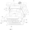
FIG. 1 illustrates a three-dimensional structural diagram of a first electromotor according to one embodiment of the present application; -
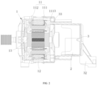
FIG. 2 illustrates a cross-sectional diagram of the first electromotor according to one embodiment of the present application; -
FIG. 3 illustrates a cross-sectional diagram of a second electromotor according to one embodiment of the present application; -
FIG. 4 illustrates an enlarged partial view of a part A shown inFIG. 3 ; -
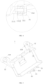
FIG. 5 illustrates a three-dimensional structural diagram of a controller cover according to one embodiment of the present application; -
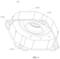
FIG. 6 illustrates a three-dimensional structural diagram of a second end cover according to one embodiment of the present application; -
FIG. 7 illustrates a cross-sectional diagram of the second end cover according to one embodiment of the present application; -
FIG. 8 illustrates a three-dimensional structural diagram of a part of the laundry machine according to one embodiment of the present application; - Where, reference numerals in the figures are listed below:
1-electromotor; 11-housing; 1111-first mounting part; 1112-second connecting hole; 1113-positioning groove; 1114-annular boss; 1115-edge flanging; 1116-bearing bore; 1117-annular groove; 112-second end cover; 12- stator; 13-rotor; 131-rotating shaft; 132-bearing; 2-controller; 3-controller cover; 31-first mounting part; 311-positioning aperture; 312-first connecting hole; 32-mounting foot; 320-second mounting part; 33-positioning pole; 34-heat dissipation fins; 4-water container. - In order to make the purpose, the technical solution and the advantages of the present application be clearer and more understandable, the present application will be further described in detail below with reference to accompanying figures and embodiments. It should be understood that the embodiments described in detail herein are merely intended to illustrate but not to limit the present application.
- It needs to be noted that, when one component is described to be "fixed to" or "arranged on" another component, this component may be directly or indirectly arranged on another component. When it is described that one component "is connected with" another component, this component may be directly or indirectly connected to another component. Orientation or position relationships indicated by terms including "upper", "lower", "left" and "right" are based on the orientation or position relationships shown in the accompanying figures and is only used for the convenience of description, instead of indicating or implying that the indicated device or element must have a specific orientation and is constructed and operated in a particular orientation, and thus should not be interpreted as limitation to the present application. As for the person of ordinary skill in the art, the specific meanings of the terms may be interpreted according to specific conditions. Terms such as "the first" and "the second" are only for the purpose of conveniently describing and should not be interpreted as indicating or implying relative importance or implicitly indicating the number of indicated technical features. "Multiple/a plurality of" means two or more unless there is an additional explicit and specific limitation.
- In order to describe the technical solutions disclosed in the present application, the technical solutions are described in detail with reference to the accompanying figures and the embodiments.
- Referring to
FIG. 1 andFIG. 2 , in one embodiment of the electromotor, theelectromotor 1 includes ahousing 11, acontroller 2 and acontroller cover 3, thecontroller 2 may be configured to control therotor 13 and other electronically controlled devices of the laundry machine. Thecontroller 2 is arranged inside or outside thecontroller cover 3, and thecontroller cover 3 is fixed on thehousing 11 of theelectromotor 1 or astator 12 of theelectromotor 1. Thehousing 11 includes afirst end cover 111 and asecond end cover 112, thefirst end cover 111 and thesecond end cover 112 are fixed on two opposite sides of thestator 12, respectively. Thecontroller cover 3 is provided with afirst mounting part 31 and asecond mounting part 320, thefirst end cover 111 or thestator 12 is provided with athird mounting part 1111, thefirst mounting part 31 and thethird mounting part 1111 are arranged to be engaged with each other, so that thecontroller cover 3 is enabled to be fixed on thefirst end cover 111 or thestator 12, and thecontroller 2 is enabled to be integrated in theelectromotor 1. Thesecond mounting part 320 is configured to be connected with awater container 4 of the laundry machine, so that a structure which is originally arranged on thehousing 11 of theelectromotor 1 is redesigned to be arranged on thecontroller cover 3, thereby simplifying the structure of thehousing 11 of theelectromotor 1. Since thehousing 11 of theelectromotor 1 needs to support therotor 13, if the structure of thehousing 11 of theelectromotor 1 is too complex, a difficulty in manufacturing the laundry machine may be increased, in order to ensure the strength of thehousing 11 of theelectromotor 1, the material and the production process of thehousing 11 of theelectromotor 1 are greatly limited. Thehousing 11 of theelectromotor 1 in this embodiment is only provided with athird mounting part 1111, so that the complexity of the structure of thefirst end cover 111 is greatly reduced, the ranges of selections of the material and the production process of thefirst end cover 111 are broadened, and the production cost of theelectromotor 1 is effectively reduced. In particular, with reference toFIG. 2 andFIG. 3 , thefirst end cover 111 inFIG. 2 is manufactured and molded by using a stretching process, and thefirst end cover 111 inFIG. 3 is manufactured and molded by using a casting process; since thefirst end cover 111 has a simple structure, thefirst end cover 111 can be manufactured and molded by using different processes according to the requirement, and the requirement on the manufacturing process of thefirst end cover 111 is low. When thefirst end cover 111 is made of a material such as resin, thefirst end cover 111 may be molded through an injection molding. Thefirst end cover 111 may be selected as a metal housing or be a resin housing, thefirst end cover 111 is simple in structure, has low performance requirement on the material, so that the production cost of thefirst end cover 111 can be greatly reduced. Moreover, thecontroller cover 3 is only used to accommodate and protect thecontroller 2, and the requirements of thecontrol cover 3 on the production process and the material is low, thus, arranging thesecond mounting part 320 on thecontroller cover 3 will not significantly increase the production difficulty and the cost. The electromotor in the aforesaid embodiment includes thehousing 11, thecontroller 2, and thecontroller cover 3. Thecontroller 2 is arranged on thecontroller cover 3, thehousing 11 includes thefirst end cover 111 and thesecond end cover 112; thecontroller cover 3 is fixed through an engagement between thefirst mounting part 31 arranged on thecontroller cover 3 and thethird mounting part 1111 arranged on thefirst end cover 111 or thestator 12; furthermore, thecontroller cover 3 is secured with thewater container 4 of the laundry machine by arranging thesecond mounting part 320 on thecontroller cover 3. In this way, thehousing 11 of theelectromotor 1 only needs to be provided with the third mountingpart 1111 secured with thecontroller cover 3. so that the structure of thefirst end cover 111 is simplified, other materials with lower price and simpler production process may be selected for thefirst end cover 111, and the cost of the laundry machine is reduced accordingly. - Referring to
FIG. 2 andFIG. 3 , in one embodiment of the present application, the second mountingpart 320 is arranged on one side of thecontroller cover 3 opposite to thecontroller 2. Thecontroller cover 3 is provided with a cavity, thecontroller 2 is arranged in the cavity, and thecontroller cover 3 is arranged to cover the outside of thefirst end cover 111, which means that, a side of thecontroller cover 3 opposite to thecontroller 2 is the outer side of thecontroller cover 3, that is, the second mountingpart 320 is arranged on the outer side of thecontroller cover 3, the first mountingpart 31 and the second mountingpart 320 are arranged on one side of thecontroller cover 3 facing thehousing 11 and one side of thecontroller cover 3 opposite to thehousing 11, respectively. In this way, when thecontroller cover 3 is connected with thewater container 4, thehousing 11 does not interfere with thewater container 4. - Referring to
FIG. 5 , in one embodiment of the present application, the surface of thecontroller cover 3 extends outwards to form a plurality of mountingfeet 32, the second mountingpart 320 is disposed on the mountingfeet 32, the mountingfeet 32 are arranged such that the second mountingpart 320 may not be limited by the structure of thecontroller cover 3, the position of the second mountingpart 320 is designed according to the structure of thewater container 4. There may be a plurality of mountingfeet 32, and each of the mountingfeet 32 is provided with at least one second mountingpart 320, such that thecontroller cover 3 can be stably fixed on thewater container 4. More specifically, there are two mountingfeet 32, the two mountingfeet 32 extend outwards from the surface of thecontroller cover 3, and the two mountingfeet 32 are arranged to be splayed. - In one embodiment, the second mounting
part 320 is a mounting hole or a mounting column. When the second mountingpart 320 is a mounting hole, thewater container 4 is provided with a mounting column, the mounting column is arranged to be inserted into the mounting hole, and the second mountingpart 320 is fixed on thewater container 4 through a fastener such as screw and a pin. Alternatively, when the second mountingpart 320 is a mounting column, thewater container 4 is provided with a mounting hole, and the mounting column is arranged to be inserted into the mounting hole. When the mounting column is inserted into the mounting hole, a cushioning element such as a gasket is arranged between the mounting hole and the mounting column, so that a vibration effect of theelectromotor 1 on thewater container 4 can be reduced. - Referring to
FIG. 1 , in one embodiment of the present application, the surface of thecontroller cover 3 is provided withheat dissipation fins 34 which greatly increase the surface area of thecontroller cover 3, so that heat generated by thecontroller 2 can be rapidly dissipated through theheat dissipation fins 34, thereby accelerating the heat dissipation rate of thecontroller 2. In one embodiment, thecontroller cover 3 is a metal cover such as an aluminum cover or an aluminum alloy cover, the metal cover has a better heat dissipation performance. Moreover, the aluminum, the aluminum alloy and other materials are prone to be molded and machined, and thus are suitable to be used for manufacturing complex structures such as the second mountingpart 320 without greatly increasing the production cost. In one embodiment, thecontroller cover 3 may also be a resin cover, when thecontroller cover 3 is the resin cover, heat dissipation fins may be disposed on thecontroller cover 3. The positions and the number of the heat dissipation fins are not limited herein. - In any one of the embodiments described above, the
controller 2 is fixedly arranged inside thecontroller cover 3 by using a fastening method such as a snap-fit manner or a fastener; as an alternative, thecontroller 2 is fixed on thehousing 11 using a fastening method such as a fastener; as yet another alternative, thecontroller 2 is received in thecontroller cover 3, and thecontroller cover 3 is fixed on thehousing 11, so that thecontroller 2 is pressed tightly between thecontroller cover 3 and thehousing 11. - In one embodiment of the present application, the first mounting
part 31 and the third mountingpart 1111 are fixedly connected through a fixing member, so that thecontroller cover 3 is fixed on thefirst end cover 111 or thestator 12. The fixing member is arranged to pass through the first mountingpart 31 and the third mountingpart 1111, the fixing member may be selected as a screw or a pin, thecontroller cover 3 and thefirst end cover 111 or thestator 12 are fixed with each other by passing through the first mountingpart 31 and the third mountingpart 1111. - In one embodiment, referring to
FIG. 2 andFIG. 5 , one side of thefirst end cover 111 or thestator 12 that faces thecontroller cover 3 is provided with apositioning groove 1113, thecontroller cover 3 is provided with apositioning column 33 correspondingly, and thepositioning column 33 is arranged to be inserted into thepositioning groove 1113 to facilitate the process of assembling and fixing thefirst end cover 111 or thestator 12 with thecontroller cover 3. Alternatively, one side of thefirst end cover 111 or thestator 12 that faces thecontroller cover 3 is provided with a positioning column, thecontroller cover 3 is provided with a positioning groove, and the positioning column is arranged to be inserted into the positioning groove to facilitate the process of assembling and fixing thefirst end cover 111 or thestator 12 with thecontroller cover 3. In the two embodiments described above, not only a mounting structure (i.e., the first mountingpart 31 and the third mounting part 1111) is arranged between thefirst end cover 111 or thestator 12 and thecontroller cover 3, an alignment structure (i.e., thepositioning column 33 and the positioning groove 1113) is also arranged between thefirst end cover 111 or thestator 12 and thecontroller cover 3, so that thefirst end cover 111 or thestator 12 and thecontroller cover 3 can be accurately assembled and secured stably. - In one embodiment, referring to
FIG. 3 andFIG. 4 , the third mountingpart 1111 is a positioning pole, the first mountingpart 31 is provided with apositioning aperture 311, and the positioning pole is inserted into thepositioning aperture 311 to fix the third mountingpart 1111 with the first mountingpart 31. As an alternative, the first mountingpart 31 is the positioning pole, the third mountingpart 1111 is provided with the positioning aperture, and the positioning pole is inserted into the positioning aperture to fix the third mountingpart 1111 with the first mountingpart 31. In one preferable embodiment, a bottom of thepositioning aperture 311 is provided with a first connectinghole 312, the positioning pole is provided with a second connectinghole 1112, and the fixing member passes through the first connectinghole 312 and the second connectinghole 1112 to fix the first mountingpart 31 with the third mountingpart 1111. The first connectinghole 312 and the second connectinghole 1112 may be unthreaded holes or threaded holes. When the first connectinghole 312 and the second connectinghole 1112 are unthreaded holes, the fixing member may be selected as a connection piece such as a pin; when one of the first connectinghole 312 and the second connectinghole 1112 is a threaded hole, and the other of the first connectinghole 312 and the second connectinghole 1112 is an unthreaded hole, the fixing member may be selected as a connection member such as a screw, and the screw passes through the optical hole to be connected to the threaded hole so as to secure the first mountingpart 31 with the third mountingpart 1111. In this embodiment, both the mounting structure and the positioning structure between thefirst end cover 111/thestator 12 and thecontroller cover 3 are arranged on the first mountingpart 31 and the third mountingpart 1111, that is, it only needs to arrange the third mountingpart 1111 on thefirst end cover 111 to simplify the structure of thefirst end cover 111 to the most extent. - More specifically, when the
first end cover 111 is a stretched end cover, the third mountingpart 1111 is the second connectinghole 1112, the first mountingpart 31 is the positioning column correspondingly, and the positioning column is provided with the first connectinghole 312. When thefirst end cover 111 is an aluminum casting end cover, the third mountingpart 1111 is a positioning column which is provided with the second connectinghole 1112, and the first mounting part is the first connectinghole 312 correspondingly. - In one embodiment, referring to
FIG. 6 , at least one of thefirst end cover 111 and thesecond end cover 112 is provided with anedge flanging 1115, due to the fact that both thefirst end cover 111 and thesecond end cover 112 are fixed on thestator 12, there is a gap between thefirst end cover 111 and thestator 12 and between thesecond end cover 112 and thestator 12, and thereby forming an air gap, if the air gap is too large, a reluctance of theelectromotor 1 is increased, and an efficiency of theelectromotor 1 is reduced. Theedge flanging 1115 is formed by folding the edge of thefirst end cover 111 and/or thesecond end cover 112, and theedge flanging 1115 comes into contact with the surface of thestator 12 tightly, so that the air gap between thefirst end cover 111 and/or thesecond end cover 112 and thestator 12 can be reduced, and the efficiency of theelectromotor 1 is ensured. The number and the distribution of theedge flanging 1115 are not limited herein, theedge flanging 1115 may be uniformly arranged on thefirst end cover 111 and/or thesecond end cover 112 circumferentially. - In one embodiment, referring to
FIG. 2 ,FIG. 3 andFIG. 7 , theelectromotor 1 includes ahousing 11, astator 12, and arotor 13. Thestator 12 is immobilized and stationary, therotor 13 rotates relative to thestator 12, and thehousing 11 is configured to support therotor 13 and have a certain protection effect on therotor 13 and thestator 12. Therotor 13 includes arotating shaft 131 and twobearings 132 distributed on two ends of therotating shaft 131 for supporting therotating shaft 131, so that therotating shaft 131 is enabled to rotate relative to thestator 12. Thefirst end cover 111 and thesecond end cover 112 are provided with twoannular bosses 1114, theannular bosses 1114 are arranged to protrude outwards from the interior of theelectromotor 1, and interiors of theannular bosses 1114 are provided with two bearingbores 1116, and the twobearings 132 are respectively arranged in the two bearingbores 1116 of thefirst end cover 111 and thesecond end cover 112. A bottom of at least one of theannular bosses 1114 is provided with a groove structure or a convex structure for enhancing the structural strengths of thefirst end cover 111 and thesecond end cover 112. The groove structure may be anannular groove 1117, an annular concave rib, etc., theannular groove 1117 and the annular concave rib may be arranged segmentally, or may be arranged to be ring-shaped as a whole. The convex structure may be such as a boss, a convex rib and the like. The bottom of theannular boss 1114 is a component close to thestator 12, and theannular groove 1117 is recessed towards the interior of the bearing bore 1116, and the arrangement of theannular groove 1117 may increase the strength of theannular boss 1114, and prevent theannular boss 1114 from being damaged or cracked when the bottom of theannular boss 1114 is subjected to a great pressure. - The present application further provides a laundry machine, the laundry machine includes the
electromotor 1 according to any one of the embodiments described above. Theelectromotor 1 is used in the laundry machine provided in the present application. Thecontroller cover 3 is fixed according to the first mountingpart 31 disposed thereon and the third mountingpart 1111 which is arranged on thehousing 11 and matches with the first mountingpart 31. Furthermore, by providing the second mountingpart 320 on thecontroller cover 3, such that thecontroller cover 3 is secured with thewater container 4 of the laundry machine. In this way, thehousing 11 of theelectromotor 1 only needs to be provided with the third mountingpart 1111 secured with thecontroller cover 3, so that theelectromotor 1 is enabled to be secured with thecontroller cover 3 which has thecontroller 2 inside it, there is no need to additionally provide other mounting structures fixedly connected with thewater container 4 of the laundry machine, so that the structure of thehousing 11 of theelectromotor 1 is simplified, other materials with lower price and simpler production process can be selected for thehousing 11 of theelectromotor 1, thereby reducing the cost of the laundry machine. - In one embodiment, referring to
FIG. 8 , the laundry machine further includes awater container 4 and a rotating drum, thewater container 4 is configured to contain water, and the rotating drum is rotatably mounted in thewater container 4. A periphery of thewater container 4 is provided with a fourth mounting part configured to be fixedly connected with the second mountingpart 320. The second mountingpart 320 is a mounting hole, and the fourth mounting part is a mounting column; as an alternative, the second mountingpart 320 is a mounting column, and the fourth mounting part is a mounting hole; the mounting column is configured to be inserted into the mounting hole. The second mountingpart 320 and the fourth mounting part may be fixedly connected through fasteners such as screws, pins, etc.
Claims (15)
- An electromotor (1) for a laundry machine comprising a controller (2) and a controller cover (3), the controller (2) is arranged on the controller cover (3); the electromotor (1) further comprises a first end cover (111) and a second end cover (112) which is secured with the first end cover (111); wherein the electromotor (1) further comprises a stator (12), the first end cover (111) and the second end cover (112) are fixed on two opposite sides of the stator (12) respectively; the controller cover (3) is provided with a first mounting part (31) configured to be secured with the first end cover (111), and a second mounting part (320) configured to be secured with a water container (4) of the laundry machine, and the first end cover (111) is provided with a third mounting part (1111) configured to be secured with the first mounting part (31).
- The electromotor (1) according to claim 1, wherein the second mounting part (320) is arranged on one side of the controller cover (3) opposite to the controller (2).
- The electromotor (1) according to claim 1, wherein a surface of the controller cover (3) protrudes outwards to form a mounting foot (32), the second mounting part (320) is arranged on the mounting foot (32), the second mounting part (320) is a mounting hole or a mounting column.
- The electromotor (1) according to claim 1, wherein a surface of the controller cover (3) is provided with heat dissipation fins (34).
- The electromotor (1) according to claim 4, wherein the controller cover (3) is the one selected from a group consisting of an aluminum cover, a cover made of aluminum alloy and a resin cover.
- The electromotor (1) according to claim 1, wherein the first mounting part (31) and the third mounting part (1111) are connected by a first fixing member, and the first fixing member is arranged to pass through the first mounting part (31) and the third mounting part (1111).
- The electromotor (1) according to claim 6, wherein one side of the first end cover (111) which faces towards the controller cover (3) is provided with a first positioning element, and the controller cover (3) is provided with a second positioning element that comes into engagement with the first positioning element; or one side of the stator (12) which faces towards the controller cover (3) is provided with a first positioning element, and the controller cover (3) is provided with a second positioning element that comes into engagement with the first positioning element.
- The electromotor (1) according to claim 7, wherein the third mounting part (1111) is the first positioning element, and the first mounting part (31) is the second positioning element;
the first positioning element is provided with a first connecting hole (312), the second positioning element is provided with a second connecting hole (1112), and the first fixing member is arranged to pass through the first connecting hole (312) and the second connecting hole (1112). - The electromotor (1) according to claim 1, wherein the controller (2) is configured to be snap-fitted into the controller cover (3) or the first end cover (111).
- The electromotor (1) according to claim 1, wherein the first end cover (111) is molded through a stretching molding process, a casting molding process, or an injection molding process.
- The electromotor (1) according to claim 1, wherein the first end cover (111) is a housing (11) made of metal or a housing (11) made of resin.
- The electromotor (1) according to claim 1, wherein the electromotor (1) further comprises a rotor (13) configured to rotate relative to the stator (12), the rotor (13) comprises a rotating shaft (131) and two bearings (132) arranged at two ends of the rotating shaft (131) respectively, the first end cover (111) and the second end cover (112) protrude outwards to form two annular bosses (1114), interiors of the two annular bosses (1114) are provided with two bearing bores (1116) for accommodating the two bearings (132), and a bottom of at least one of the two annular bosses (1114) is provided with a groove structure or a convex structure, wherein the bottom of the annular boss (1114) is a component close to the stator (12).
- The electromotor (1) according to claim 12, wherein the first end cover (111) and/or the second end cover (112) is provided with at least one edge flanging (1115) which comes into contact with the stator (12) tightly.
- The electromotor (1) according to claim 12, wherein the groove structure is an annular groove (1117); the convex structure is an annular boss or the convex structure comprises a plurality of separately arranged convex ribs which are enclosed to be ring-shaped.
- A laundry machine, wherein the laundry machine comprises the electromotor (1) according to any one of claims 1-14, and a water container (4) configured to be secured with the second mounting part (320) of the second controller cover (3).
Applications Claiming Priority (2)
| Application Number | Priority Date | Filing Date | Title |
|---|---|---|---|
| CN202010968683.5A CN114268183A (en) | 2020-09-15 | 2020-09-15 | Electric motor and washing machine |
| PCT/CN2020/137628 WO2022057130A1 (en) | 2020-09-15 | 2020-12-18 | Motor and washing machine |
Publications (3)
| Publication Number | Publication Date |
|---|---|
| EP4007128A1 EP4007128A1 (en) | 2022-06-01 |
| EP4007128A4 EP4007128A4 (en) | 2022-11-30 |
| EP4007128B1 true EP4007128B1 (en) | 2025-05-21 |
Family
ID=80490584
Family Applications (1)
| Application Number | Title | Priority Date | Filing Date |
|---|---|---|---|
| EP20950480.2A Active EP4007128B1 (en) | 2020-09-15 | 2020-12-18 | Motor and washing machine |
Country Status (7)
| Country | Link |
|---|---|
| US (1) | US12136852B2 (en) |
| EP (1) | EP4007128B1 (en) |
| JP (1) | JP7305036B2 (en) |
| KR (1) | KR102650000B1 (en) |
| CN (3) | CN114268183A (en) |
| PL (1) | PL4007128T3 (en) |
| WO (1) | WO2022057130A1 (en) |
Families Citing this family (1)
| Publication number | Priority date | Publication date | Assignee | Title |
|---|---|---|---|---|
| CN114268183A (en) * | 2020-09-15 | 2022-04-01 | 佛山市威灵洗涤电机制造有限公司 | Electric motor and washing machine |
Family Cites Families (65)
| Publication number | Priority date | Publication date | Assignee | Title |
|---|---|---|---|---|
| DE608371C (en) | 1931-06-24 | 1935-01-24 | Aeg | Clamp to hold the stator core of electrical machines together |
| DE2148827A1 (en) | 1971-09-30 | 1973-04-12 | Siemens Ag | ELECTRIC MOTOR WITH TWO BEARING PLATES OVERALLING ITS STAND PLATE, OR ENCLOSED |
| JPS60202116A (en) | 1984-03-28 | 1985-10-12 | Toho Rayon Co Ltd | Epoxy resin composition |
| US4668898A (en) * | 1986-04-21 | 1987-05-26 | General Electric Company | Electronically commutated motor |
| JPH01321848A (en) | 1988-06-21 | 1989-12-27 | Sanyo Electric Co Ltd | Rotary electric machine |
| EP0640507B1 (en) | 1992-05-12 | 2003-04-16 | Seiko Epson Corporation | Electric vehicle |
| DE9301825U1 (en) | 1993-02-10 | 1994-06-16 | Robert Bosch Gmbh, 70469 Stuttgart | Electrical machine, in particular three-phase generator for internal combustion engines |
| JPH07212993A (en) | 1994-01-18 | 1995-08-11 | Matsushita Electric Ind Co Ltd | Motor stator core |
| JPH08266001A (en) | 1995-03-20 | 1996-10-11 | Fujitsu General Ltd | Electric motor |
| DE19532506B4 (en) | 1995-09-02 | 2016-05-25 | Robert Bosch Gmbh | Electric machine |
| KR200160335Y1 (en) * | 1997-10-28 | 1999-11-01 | 구자홍 | The motor controller case and back cover of a washing machine |
| EP1416611B1 (en) | 1999-12-14 | 2005-04-27 | Mitsubishi Denki Kabushiki Kaisha | Alternator |
| JP2001251806A (en) | 2000-03-01 | 2001-09-14 | Hitachi Ltd | AC generator for vehicles |
| US6479916B1 (en) * | 2001-04-26 | 2002-11-12 | General Electric Company | Method and apparatus for mounting electronic motor controls |
| TW525871U (en) | 2001-11-06 | 2003-03-21 | Lidashi Industry Co Ltd | Improved structure of motor housing |
| JP2005304213A (en) | 2004-04-14 | 2005-10-27 | Toyota Motor Corp | Stator fixing structure |
| JP4583191B2 (en) | 2005-01-28 | 2010-11-17 | 三菱電機株式会社 | Rotating electric machine |
| US7352092B2 (en) * | 2005-08-22 | 2008-04-01 | Emerson Electric Co. | Integrated motor and controller assemblies for horizontal axis washing machines |
| JP4811114B2 (en) | 2006-05-15 | 2011-11-09 | トヨタ自動車株式会社 | Stator fixing structure and vehicle |
| WO2007139129A1 (en) * | 2006-06-01 | 2007-12-06 | Panasonic Corporation | Brushless motor for washing machine and washing machine having the brushless motor mounted therein |
| ITMI20070304U1 (en) * | 2007-09-11 | 2009-03-12 | Askoll Holding Srl | SUPPORT FOR FIXING AN ELECTRIC MOTOR TO A WASHING MACHINE OR SIMILAR APPLIANCE |
| US9093884B2 (en) * | 2010-10-20 | 2015-07-28 | Nidec Motor Corporation | Integrated motor and control |
| DE102010062824A1 (en) * | 2010-12-10 | 2012-06-14 | BSH Bosch und Siemens Hausgeräte GmbH | Housingless electric motor for a household appliance |
| JP5485926B2 (en) | 2011-02-25 | 2014-05-07 | 東芝産業機器製造株式会社 | Manufacturing method of stator core |
| JP5898876B2 (en) | 2011-07-26 | 2016-04-06 | 山洋電気株式会社 | Electrical equipment |
| CN202187199U (en) * | 2011-08-05 | 2012-04-11 | 常州新亚电机有限公司 | Integral motor and controller assembly |
| CN202150773U (en) * | 2011-08-05 | 2012-02-22 | 无锡艾柯威科技有限公司 | Controller assembly and motor applied by same |
| JP5742570B2 (en) | 2011-08-09 | 2015-07-01 | トヨタ自動車株式会社 | Electric vehicle drive device |
| KR20130063212A (en) * | 2011-12-06 | 2013-06-14 | 삼성전기주식회사 | Motor of outer rotor type |
| CN102587081A (en) * | 2012-03-12 | 2012-07-18 | 无锡艾柯威科技有限公司 | Installation structure of motor controller for vertical axis washing machine |
| CN202721533U (en) * | 2012-06-29 | 2013-02-06 | 中山大洋电机股份有限公司 | A New Type of End Cover and Its Applied External Rotor Motor |
| JP5660400B2 (en) | 2012-08-03 | 2015-01-28 | 株式会社デンソー | Rotating electric machine and electric power steering apparatus using the same |
| CN202721563U (en) * | 2012-08-20 | 2013-02-06 | 常州新亚电机有限公司 | Motor end cap and controller assembly |
| CN102801253A (en) * | 2012-08-20 | 2012-11-28 | 常州新亚电机有限公司 | Motor and controller assembly |
| CN203660711U (en) | 2013-12-09 | 2014-06-18 | 中山大洋电机制造有限公司 | Stretching end cover motor |
| CN203883586U (en) | 2014-05-28 | 2014-10-15 | 中山大洋电机股份有限公司 | Motor |
| CN105463774B (en) * | 2014-06-30 | 2019-11-12 | 青岛海尔洗衣机有限公司 | a clutch device |
| CN203933222U (en) * | 2014-07-16 | 2014-11-05 | 浙江伟康电机有限公司 | Stretching iron end cover structure for roller washing machine series excited machine |
| CN104158333B (en) * | 2014-07-29 | 2017-11-24 | 佛山市威灵洗涤电机制造有限公司 | Electric motor end cap and the integrated motor with it and split type motor |
| US20160056681A1 (en) * | 2014-08-21 | 2016-02-25 | Nidec Motor Corporation | Integrated motor and controller with internal heat sink and snap-on dripshield |
| CN104682607A (en) * | 2015-03-10 | 2015-06-03 | 佛山市威灵洗涤电机制造有限公司 | Rear end cover of motor, integrated motor and washing machine |
| CN204794453U (en) | 2015-05-21 | 2015-11-18 | 中山大洋电机制造有限公司 | A stretching end cap motor |
| CN204733005U (en) | 2015-06-30 | 2015-10-28 | 中山大洋电机股份有限公司 | An iron shell motor |
| CN204794462U (en) | 2015-07-06 | 2015-11-18 | 黄炜琦 | Pull end lid motor |
| CN105048705A (en) * | 2015-08-06 | 2015-11-11 | 佛山市威灵洗涤电机制造有限公司 | Motor and washing machine with same |
| CN205039640U (en) * | 2015-10-14 | 2016-02-17 | 苏州三星电子有限公司 | Drum type washing machine , motor and combination formula rear end cap thereof |
| CN105386278B (en) | 2015-11-26 | 2018-01-16 | 佛山市威灵洗涤电机制造有限公司 | The electric motor mounting structure of household electrical appliance |
| CN105656251B (en) * | 2016-03-28 | 2019-01-08 | 佛山市威灵洗涤电机制造有限公司 | Electric machine assembly and washing machine |
| CN106253572A (en) * | 2016-07-28 | 2016-12-21 | 佛山市威灵洗涤电机制造有限公司 | Household electrical appliance |
| CN206962600U (en) | 2017-07-26 | 2018-02-02 | 佛山市威灵洗涤电机制造有限公司 | Motor and roller washing machine |
| CN107313948B (en) | 2017-07-31 | 2023-07-18 | 广东威灵电机制造有限公司 | Motor pump and dish washer |
| CN107404174B (en) * | 2017-08-28 | 2024-03-26 | 广东威灵电机制造有限公司 | Motor shell and motor |
| CN109962541A (en) | 2017-12-26 | 2019-07-02 | 上海海立电器有限公司 | Motor stator, compressor, and method for manufacturing the same |
| CN108134464A (en) * | 2018-02-10 | 2018-06-08 | 中山市科艺电机有限公司 | Motor rotor and sewing machine energy-saving motor and sewing machine using the rotor |
| CN108551223B (en) * | 2018-06-14 | 2024-10-22 | 广东威灵电机制造有限公司 | End cover for motor, motor with end cover and washing machine |
| CN110768474B (en) * | 2018-07-27 | 2025-07-25 | 广东威灵电机制造有限公司 | Motor and washing machine with same |
| CN208489737U (en) * | 2018-08-20 | 2019-02-12 | 广东威灵电机制造有限公司 | End cap, motor and washing machine for motor |
| CN208608816U (en) * | 2018-09-06 | 2019-03-15 | 广东威灵电机制造有限公司 | Motor |
| JP2020054628A (en) * | 2018-10-02 | 2020-04-09 | 三星電子株式会社Samsung Electronics Co.,Ltd. | Washing machine |
| CN209233673U (en) * | 2018-12-11 | 2019-08-09 | 常州雷利电机科技有限公司 | Electronic water pump and controller mounting structure for the electronic water pump |
| CN210273657U (en) * | 2019-08-01 | 2020-04-07 | 莱克电气股份有限公司 | Motor and motor controller integrated installation mechanism |
| CN212751976U (en) | 2020-09-15 | 2021-03-19 | 佛山市威灵洗涤电机制造有限公司 | Motor and washing machine |
| CN114268183A (en) * | 2020-09-15 | 2022-04-01 | 佛山市威灵洗涤电机制造有限公司 | Electric motor and washing machine |
| CN212935583U (en) | 2020-09-15 | 2021-04-09 | 佛山市威灵洗涤电机制造有限公司 | Stator core punching sheet, stator core and motor |
| CN212343506U (en) * | 2020-09-15 | 2021-01-12 | 佛山市威灵洗涤电机制造有限公司 | Motor and washing machine |
-
2020
- 2020-09-15 CN CN202010968683.5A patent/CN114268183A/en active Pending
- 2020-09-15 CN CN202111454864.7A patent/CN114204728B/en active Active
- 2020-09-15 CN CN202111453050.1A patent/CN114172302B/en active Active
- 2020-12-18 PL PL20950480.2T patent/PL4007128T3/en unknown
- 2020-12-18 KR KR1020227006870A patent/KR102650000B1/en active Active
- 2020-12-18 JP JP2022513595A patent/JP7305036B2/en active Active
- 2020-12-18 EP EP20950480.2A patent/EP4007128B1/en active Active
- 2020-12-18 WO PCT/CN2020/137628 patent/WO2022057130A1/en not_active Ceased
-
2022
- 2022-02-28 US US17/682,519 patent/US12136852B2/en active Active
Also Published As
| Publication number | Publication date |
|---|---|
| EP4007128A4 (en) | 2022-11-30 |
| WO2022057130A1 (en) | 2022-03-24 |
| JP7305036B2 (en) | 2023-07-07 |
| KR20220041184A (en) | 2022-03-31 |
| JP2022553119A (en) | 2022-12-22 |
| PL4007128T3 (en) | 2025-09-08 |
| CN114204728B (en) | 2023-11-14 |
| CN114172302B (en) | 2024-01-05 |
| EP4007128A1 (en) | 2022-06-01 |
| CN114204728A (en) | 2022-03-18 |
| US12136852B2 (en) | 2024-11-05 |
| KR102650000B1 (en) | 2024-03-22 |
| CN114172302A (en) | 2022-03-11 |
| CN114268183A (en) | 2022-04-01 |
| US20220181924A1 (en) | 2022-06-09 |
Similar Documents
| Publication | Publication Date | Title |
|---|---|---|
| EP2375544B1 (en) | Motor for washing machine and washing machine having the same | |
| JP6872036B2 (en) | Inverter device and electric compressor | |
| US20090064726A1 (en) | Driving apparatus for washing machine | |
| JP2005193030A (en) | Motor for washing machine | |
| KR102596664B1 (en) | Motor | |
| EP0354158B1 (en) | Minimum height motor assembly using aluminum endshields | |
| JP2019009912A (en) | Electronic apparatus | |
| JP2013039011A (en) | Motor | |
| US12136852B2 (en) | Electromotor and laundry machine | |
| CN212343506U (en) | Motor and washing machine | |
| CN219420470U (en) | Drive assembly and washing equipment | |
| CN213185851U (en) | Linear stepping motor device | |
| US12188479B2 (en) | Fan assembly of clothes treatment device and clothes treatment device | |
| US20220181944A1 (en) | Electric motor and washing machine | |
| KR20170119792A (en) | Fan motor and electronic device having the same | |
| CN212935629U (en) | Motor and washing machine | |
| CN219568410U (en) | Base assembly for clothes treatment equipment and clothes treatment equipment with base assembly | |
| WO2018127314A1 (en) | A washing machine wherein the electric motor is integrated to the tub | |
| KR100582298B1 (en) | Motor mounting structure of washing machine and rotor structure of washing machine motor | |
| US9970145B2 (en) | Fabric treating machine | |
| KR101040276B1 (en) | Fastening structure of rotor frame and bush of motor for washing machine | |
| CN109861585A (en) | A double-acting piezoelectric generator | |
| CN109957950A (en) | A wall-mounted washing machine | |
| CN105305694A (en) | Motor and housing assembly for same | |
| JPS6315647A (en) | Motor mounting device |
Legal Events
| Date | Code | Title | Description |
|---|---|---|---|
| STAA | Information on the status of an ep patent application or granted ep patent |
Free format text: STATUS: UNKNOWN |
|
| STAA | Information on the status of an ep patent application or granted ep patent |
Free format text: STATUS: THE INTERNATIONAL PUBLICATION HAS BEEN MADE |
|
| PUAI | Public reference made under article 153(3) epc to a published international application that has entered the european phase |
Free format text: ORIGINAL CODE: 0009012 |
|
| STAA | Information on the status of an ep patent application or granted ep patent |
Free format text: STATUS: REQUEST FOR EXAMINATION WAS MADE |
|
| 17P | Request for examination filed |
Effective date: 20220228 |
|
| AK | Designated contracting states |
Kind code of ref document: A1 Designated state(s): AL AT BE BG CH CY CZ DE DK EE ES FI FR GB GR HR HU IE IS IT LI LT LU LV MC MK MT NL NO PL PT RO RS SE SI SK SM TR |
|
| REG | Reference to a national code |
Ref legal event code: R079 Ref country code: DE Ref document number: 602020051903 Country of ref document: DE Free format text: PREVIOUS MAIN CLASS: H02K0005040000 Ipc: H02K0011300000 |
|
| A4 | Supplementary search report drawn up and despatched |
Effective date: 20221031 |
|
| RIC1 | Information provided on ipc code assigned before grant |
Ipc: D06F 37/30 20200101ALN20221025BHEP Ipc: D06F 37/20 20060101ALN20221025BHEP Ipc: H02K 5/08 20060101ALN20221025BHEP Ipc: H02K 5/06 20060101ALN20221025BHEP Ipc: H02K 5/18 20060101ALN20221025BHEP Ipc: H02K 7/14 20060101ALI20221025BHEP Ipc: H02K 5/04 20060101ALI20221025BHEP Ipc: H02K 5/16 20060101ALI20221025BHEP Ipc: H02K 5/15 20060101ALI20221025BHEP Ipc: H02K 11/30 20160101AFI20221025BHEP |
|
| DAV | Request for validation of the european patent (deleted) | ||
| DAX | Request for extension of the european patent (deleted) | ||
| GRAP | Despatch of communication of intention to grant a patent |
Free format text: ORIGINAL CODE: EPIDOSNIGR1 |
|
| STAA | Information on the status of an ep patent application or granted ep patent |
Free format text: STATUS: GRANT OF PATENT IS INTENDED |
|
| RIC1 | Information provided on ipc code assigned before grant |
Ipc: D06F 37/30 20200101ALN20250203BHEP Ipc: D06F 37/20 20060101ALN20250203BHEP Ipc: H02K 5/08 20060101ALN20250203BHEP Ipc: H02K 5/06 20060101ALN20250203BHEP Ipc: H02K 5/18 20060101ALN20250203BHEP Ipc: H02K 7/14 20060101ALI20250203BHEP Ipc: H02K 5/04 20060101ALI20250203BHEP Ipc: H02K 5/16 20060101ALI20250203BHEP Ipc: H02K 5/15 20060101ALI20250203BHEP Ipc: H02K 11/30 20160101AFI20250203BHEP |
|
| INTG | Intention to grant announced |
Effective date: 20250213 |
|
| GRAS | Grant fee paid |
Free format text: ORIGINAL CODE: EPIDOSNIGR3 |
|
| GRAA | (expected) grant |
Free format text: ORIGINAL CODE: 0009210 |
|
| STAA | Information on the status of an ep patent application or granted ep patent |
Free format text: STATUS: THE PATENT HAS BEEN GRANTED |
|
| AK | Designated contracting states |
Kind code of ref document: B1 Designated state(s): AL AT BE BG CH CY CZ DE DK EE ES FI FR GB GR HR HU IE IS IT LI LT LU LV MC MK MT NL NO PL PT RO RS SE SI SK SM TR |
|
| RAP3 | Party data changed (applicant data changed or rights of an application transferred) |
Owner name: HUAI'AN WELLING MOTOR MANUFACTURING CO., LTD. Owner name: FOSHAN WELLING WASHER MOTOR MANUFACTURING CO.,LTD. |
|
| REG | Reference to a national code |
Ref country code: GB Ref legal event code: FG4D |
|
| REG | Reference to a national code |
Ref country code: CH Ref legal event code: EP |
|
| REG | Reference to a national code |
Ref country code: DE Ref legal event code: R096 Ref document number: 602020051903 Country of ref document: DE |
|
| REG | Reference to a national code |
Ref country code: IE Ref legal event code: FG4D |
|
| REG | Reference to a national code |
Ref country code: SK Ref legal event code: T3 Ref document number: E 46775 Country of ref document: SK Ref country code: NL Ref legal event code: MP Effective date: 20250521 |
|
| PG25 | Lapsed in a contracting state [announced via postgrant information from national office to epo] |
Ref country code: FI Free format text: LAPSE BECAUSE OF FAILURE TO SUBMIT A TRANSLATION OF THE DESCRIPTION OR TO PAY THE FEE WITHIN THE PRESCRIBED TIME-LIMIT Effective date: 20250521 Ref country code: PT Free format text: LAPSE BECAUSE OF FAILURE TO SUBMIT A TRANSLATION OF THE DESCRIPTION OR TO PAY THE FEE WITHIN THE PRESCRIBED TIME-LIMIT Effective date: 20250922 Ref country code: ES Free format text: LAPSE BECAUSE OF FAILURE TO SUBMIT A TRANSLATION OF THE DESCRIPTION OR TO PAY THE FEE WITHIN THE PRESCRIBED TIME-LIMIT Effective date: 20250521 |
|
| REG | Reference to a national code |
Ref country code: LT Ref legal event code: MG9D |
|
| PG25 | Lapsed in a contracting state [announced via postgrant information from national office to epo] |
Ref country code: NO Free format text: LAPSE BECAUSE OF FAILURE TO SUBMIT A TRANSLATION OF THE DESCRIPTION OR TO PAY THE FEE WITHIN THE PRESCRIBED TIME-LIMIT Effective date: 20250821 Ref country code: GR Free format text: LAPSE BECAUSE OF FAILURE TO SUBMIT A TRANSLATION OF THE DESCRIPTION OR TO PAY THE FEE WITHIN THE PRESCRIBED TIME-LIMIT Effective date: 20250822 |
|
| PG25 | Lapsed in a contracting state [announced via postgrant information from national office to epo] |
Ref country code: NL Free format text: LAPSE BECAUSE OF FAILURE TO SUBMIT A TRANSLATION OF THE DESCRIPTION OR TO PAY THE FEE WITHIN THE PRESCRIBED TIME-LIMIT Effective date: 20250521 |
|
| PG25 | Lapsed in a contracting state [announced via postgrant information from national office to epo] |
Ref country code: BG Free format text: LAPSE BECAUSE OF FAILURE TO SUBMIT A TRANSLATION OF THE DESCRIPTION OR TO PAY THE FEE WITHIN THE PRESCRIBED TIME-LIMIT Effective date: 20250521 |
|
| PG25 | Lapsed in a contracting state [announced via postgrant information from national office to epo] |
Ref country code: HR Free format text: LAPSE BECAUSE OF FAILURE TO SUBMIT A TRANSLATION OF THE DESCRIPTION OR TO PAY THE FEE WITHIN THE PRESCRIBED TIME-LIMIT Effective date: 20250521 |
|
| PG25 | Lapsed in a contracting state [announced via postgrant information from national office to epo] |
Ref country code: RS Free format text: LAPSE BECAUSE OF FAILURE TO SUBMIT A TRANSLATION OF THE DESCRIPTION OR TO PAY THE FEE WITHIN THE PRESCRIBED TIME-LIMIT Effective date: 20250821 |
|
| PG25 | Lapsed in a contracting state [announced via postgrant information from national office to epo] |
Ref country code: IS Free format text: LAPSE BECAUSE OF FAILURE TO SUBMIT A TRANSLATION OF THE DESCRIPTION OR TO PAY THE FEE WITHIN THE PRESCRIBED TIME-LIMIT Effective date: 20250921 |
|
| PG25 | Lapsed in a contracting state [announced via postgrant information from national office to epo] |
Ref country code: LV Free format text: LAPSE BECAUSE OF FAILURE TO SUBMIT A TRANSLATION OF THE DESCRIPTION OR TO PAY THE FEE WITHIN THE PRESCRIBED TIME-LIMIT Effective date: 20250521 |
|
| REG | Reference to a national code |
Ref country code: AT Ref legal event code: MK05 Ref document number: 1797669 Country of ref document: AT Kind code of ref document: T Effective date: 20250521 |
|
| PG25 | Lapsed in a contracting state [announced via postgrant information from national office to epo] |
Ref country code: AT Free format text: LAPSE BECAUSE OF FAILURE TO SUBMIT A TRANSLATION OF THE DESCRIPTION OR TO PAY THE FEE WITHIN THE PRESCRIBED TIME-LIMIT Effective date: 20250521 Ref country code: DK Free format text: LAPSE BECAUSE OF FAILURE TO SUBMIT A TRANSLATION OF THE DESCRIPTION OR TO PAY THE FEE WITHIN THE PRESCRIBED TIME-LIMIT Effective date: 20250521 Ref country code: SM Free format text: LAPSE BECAUSE OF FAILURE TO SUBMIT A TRANSLATION OF THE DESCRIPTION OR TO PAY THE FEE WITHIN THE PRESCRIBED TIME-LIMIT Effective date: 20250521 |
|
| PGFP | Annual fee paid to national office [announced via postgrant information from national office to epo] |
Ref country code: IT Payment date: 20251212 Year of fee payment: 6 |
|
| PGFP | Annual fee paid to national office [announced via postgrant information from national office to epo] |
Ref country code: TR Payment date: 20251128 Year of fee payment: 6 |
|
| PG25 | Lapsed in a contracting state [announced via postgrant information from national office to epo] |
Ref country code: CZ Free format text: LAPSE BECAUSE OF FAILURE TO SUBMIT A TRANSLATION OF THE DESCRIPTION OR TO PAY THE FEE WITHIN THE PRESCRIBED TIME-LIMIT Effective date: 20250521 |
|
| PGFP | Annual fee paid to national office [announced via postgrant information from national office to epo] |
Ref country code: PL Payment date: 20251202 Year of fee payment: 6 |
|
| PG25 | Lapsed in a contracting state [announced via postgrant information from national office to epo] |
Ref country code: EE Free format text: LAPSE BECAUSE OF FAILURE TO SUBMIT A TRANSLATION OF THE DESCRIPTION OR TO PAY THE FEE WITHIN THE PRESCRIBED TIME-LIMIT Effective date: 20250521 |
|
| PG25 | Lapsed in a contracting state [announced via postgrant information from national office to epo] |
Ref country code: RO Free format text: LAPSE BECAUSE OF FAILURE TO SUBMIT A TRANSLATION OF THE DESCRIPTION OR TO PAY THE FEE WITHIN THE PRESCRIBED TIME-LIMIT Effective date: 20250521 |
|
| PGFP | Annual fee paid to national office [announced via postgrant information from national office to epo] |
Ref country code: SK Payment date: 20251127 Year of fee payment: 6 |
|
| REG | Reference to a national code |
Ref country code: DE Ref legal event code: R097 Ref document number: 602020051903 Country of ref document: DE |
|
| PLBE | No opposition filed within time limit |
Free format text: ORIGINAL CODE: 0009261 |
|
| STAA | Information on the status of an ep patent application or granted ep patent |
Free format text: STATUS: NO OPPOSITION FILED WITHIN TIME LIMIT |
|
| REG | Reference to a national code |
Ref country code: CH Ref legal event code: L10 Free format text: ST27 STATUS EVENT CODE: U-0-0-L10-L00 (AS PROVIDED BY THE NATIONAL OFFICE) Effective date: 20260402 |
|
| 26N | No opposition filed |
Effective date: 20260224 |