EP4007086A1 - Line tube adapter assembly and endoscope - Google Patents
Line tube adapter assembly and endoscope Download PDFInfo
- Publication number
- EP4007086A1 EP4007086A1 EP20861370.3A EP20861370A EP4007086A1 EP 4007086 A1 EP4007086 A1 EP 4007086A1 EP 20861370 A EP20861370 A EP 20861370A EP 4007086 A1 EP4007086 A1 EP 4007086A1
- Authority
- EP
- European Patent Office
- Prior art keywords
- line
- housing
- base
- limiting part
- storage device
- Prior art date
- Legal status (The legal status is an assumption and is not a legal conclusion. Google has not performed a legal analysis and makes no representation as to the accuracy of the status listed.)
- Granted
Links
Images


Classifications
-
- G—PHYSICS
- G02—OPTICS
- G02B—OPTICAL ELEMENTS, SYSTEMS OR APPARATUS
- G02B23/00—Telescopes, e.g. binoculars; Periscopes; Instruments for viewing the inside of hollow bodies; Viewfinders; Optical aiming or sighting devices
- G02B23/24—Instruments or systems for viewing the inside of hollow bodies, e.g. fibrescopes
-
- A—HUMAN NECESSITIES
- A61—MEDICAL OR VETERINARY SCIENCE; HYGIENE
- A61B—DIAGNOSIS; SURGERY; IDENTIFICATION
- A61B1/00—Instruments for performing medical examinations of the interior of cavities or tubes of the body by visual or photographical inspection, e.g. endoscopes; Illuminating arrangements therefor
- A61B1/00112—Connection or coupling means
- A61B1/00114—Electrical cables in or with an endoscope
-
- A—HUMAN NECESSITIES
- A61—MEDICAL OR VETERINARY SCIENCE; HYGIENE
- A61B—DIAGNOSIS; SURGERY; IDENTIFICATION
- A61B1/00—Instruments for performing medical examinations of the interior of cavities or tubes of the body by visual or photographical inspection, e.g. endoscopes; Illuminating arrangements therefor
- A61B1/00112—Connection or coupling means
- A61B1/00121—Connectors, fasteners and adapters, e.g. on the endoscope handle
- A61B1/00124—Connectors, fasteners and adapters, e.g. on the endoscope handle electrical, e.g. electrical plug-and-socket connection
-
- G—PHYSICS
- G02—OPTICS
- G02B—OPTICAL ELEMENTS, SYSTEMS OR APPARATUS
- G02B23/00—Telescopes, e.g. binoculars; Periscopes; Instruments for viewing the inside of hollow bodies; Viewfinders; Optical aiming or sighting devices
- G02B23/24—Instruments or systems for viewing the inside of hollow bodies, e.g. fibrescopes
- G02B23/2476—Non-optical details, e.g. housings, mountings, supports
-
- H—ELECTRICITY
- H01—ELECTRIC ELEMENTS
- H01R—ELECTRICALLY-CONDUCTIVE CONNECTIONS; STRUCTURAL ASSOCIATIONS OF A PLURALITY OF MUTUALLY-INSULATED ELECTRICAL CONNECTING ELEMENTS; COUPLING DEVICES; CURRENT COLLECTORS
- H01R13/00—Details of coupling devices of the kinds covered by groups H01R12/70 or H01R24/00 - H01R33/00
- H01R13/72—Means for accommodating flexible lead within the holder
-
- H—ELECTRICITY
- H01—ELECTRIC ELEMENTS
- H01R—ELECTRICALLY-CONDUCTIVE CONNECTIONS; STRUCTURAL ASSOCIATIONS OF A PLURALITY OF MUTUALLY-INSULATED ELECTRICAL CONNECTING ELEMENTS; COUPLING DEVICES; CURRENT COLLECTORS
- H01R13/00—Details of coupling devices of the kinds covered by groups H01R12/70 or H01R24/00 - H01R33/00
- H01R13/73—Means for mounting coupling parts to apparatus or structures, e.g. to a wall
-
- H—ELECTRICITY
- H01—ELECTRIC ELEMENTS
- H01R—ELECTRICALLY-CONDUCTIVE CONNECTIONS; STRUCTURAL ASSOCIATIONS OF A PLURALITY OF MUTUALLY-INSULATED ELECTRICAL CONNECTING ELEMENTS; COUPLING DEVICES; CURRENT COLLECTORS
- H01R31/00—Coupling parts supported only by co-operation with counterpart
- H01R31/06—Intermediate parts for linking two coupling parts, e.g. adapter
-
- H—ELECTRICITY
- H01—ELECTRIC ELEMENTS
- H01R—ELECTRICALLY-CONDUCTIVE CONNECTIONS; STRUCTURAL ASSOCIATIONS OF A PLURALITY OF MUTUALLY-INSULATED ELECTRICAL CONNECTING ELEMENTS; COUPLING DEVICES; CURRENT COLLECTORS
- H01R13/00—Details of coupling devices of the kinds covered by groups H01R12/70 or H01R24/00 - H01R33/00
- H01R13/46—Bases; Cases
- H01R13/516—Means for holding or embracing insulating body, e.g. casing, hoods
-
- H—ELECTRICITY
- H01—ELECTRIC ELEMENTS
- H01R—ELECTRICALLY-CONDUCTIVE CONNECTIONS; STRUCTURAL ASSOCIATIONS OF A PLURALITY OF MUTUALLY-INSULATED ELECTRICAL CONNECTING ELEMENTS; COUPLING DEVICES; CURRENT COLLECTORS
- H01R2201/00—Connectors or connections adapted for particular applications
- H01R2201/12—Connectors or connections adapted for particular applications for medicine and surgery
Definitions
- the present application relates to the technical field of communication connections, and more particularly to a line tube adapter assembly and an endoscope.
- Such line tube adapters generally include a housing, a line tube, and a strip line connector accommodated between the housing and the line tube.
- the strip line connector comprises a base, a transmission line, and a communication port.
- the base is accommodated in the housing and fixed to the housing, the transmission line and the communication port are respectively connected to two ends of the base, one end of the transmission line away from the base extends from the housing to one end of the line tube away from the housing and is connected to the above-mentioned industrial or medical equipment, and the communication port is configured to connect to the above-mentioned external equipment to realize a communication or charging and discharging process with the external equipment.
- the inventor of the present invention has found in the course of carrying out the present invention that: at present, the shell and the line tube of the line tube adapter are sometimes tightly fitted and fixed by means of stamping; since the transmission line is overlong and is in a disordered state both in the shell and the line tube, in the process of stamping and tightly fitting the shell and the line tube, the shell or the line tube is easily squeezed strongly against the transmission line to cause the transmission line to be damaged, thereby affecting the normal communication connection between the above-mentioned industrial or medical equipment and the external equipment, resulting in low user satisfaction degree.
- Embodiments of the present invention are intended to provide a line tube adapter assembly and an endoscope to solve the present technical problem that a shell of a line tube adapter and the line tube may easily damage a transmission line in a matching process.
- the present invention solves the technical problem thereof by using the following technical solutions.
- a line tube adapter assembly comprises:
- the accommodation space is a through-hole extending through the line storage device from one end close to the base to one end away from the base.
- an outer wall of the line storage device is further provided with a side opening communicating with the accommodation space; the accommodation space always communicates with the side opening from one end close to the base to one end away from the base.
- the line storage device is integrally formed with the base.
- the line tube adapter assembly further comprises a first limiting part and a second limiting part adapted to the first limiting part, wherein the first limiting part is located in the accommodation cavity and provided on an inner wall of the housing, and the second limiting part is provided on an outer wall of the base, the first limiting part and the second limiting part matching to circumferentially fix the connector and the housing.
- the inner wall of the housing is provided with a first plane, the first plane being the first limiting part, and the outer wall of the base is provided with a second plane, the second plane being the second limiting part, and the first plane is fitted with the second plane.
- the first limiting part is a limiting protrusion extending from the inner wall of the housing to the center of the housing
- the second limiting part is a limiting groove extending from the outer wall of the base to the center of the base and adapted to the limiting protrusion
- circumferential fixing is achieved between the housing and the connector through the matching of the limiting protrusion and the limiting groove
- the first limiting part is a limiting groove extending from the inner wall of the housing to a direction away from the center of the housing
- the second limiting part is a limiting protrusion extending from the outer wall of the base to a direction away from the center of the base and adapted to the limiting groove
- circumferential fixing is achieved between the housing and the connector through the matching of the limiting groove and the limiting protrusion.
- the line tube adapter assembly of claim 1 further comprises a third limiting part, and a fourth limiting part adapted to the third limiting part, wherein the third limiting part is located in the accommodation cavity and is provided on an inner wall of the housing, the fourth limiting part is provided on an outer wall of the line storage device, and the third limiting part and the fourth limiting part match to circumferentially fix the line storage device and the housing.
- the inner wall of the housing is provided with a third plane, the third plane being the third limiting part, and the outer wall of the line storage device is provided with a fourth plane, the fourth plane being the fourth limiting part, and the third plane is fitted with the fourth plane.
- the accommodation space is a through-hole extending through the line storage device from one end close to the base to one end away from the base;
- the connector further comprises a communication port provided at one end of the base away from the transmission line, the communication port being connected to the transmission line.
- the housing is threadedly connected to the line tube.
- the inner side wall of the housing is provided with a centrally extending flange, one end of the base away from the transmission line abutting against the flange, one end of the base away from the flange abutting against or being fixed to the line storage device, and one end of the line tube extending into the accommodation cavity, abutting against the line storage device, and being threadedly connected to the housing.
- the present invention solves the technical problem thereof by further using the following technical solutions.
- An endoscope comprises an endoscope body, and the above-mentioned line tube adapter assembly, one end of the transmission line away from the base being connected to the endoscope body.
- An embodiment of the present invention provides a line tube adapter assembly comprising a housing, a connector, a line storage device, and a line tube, wherein the connector comprises a base and a transmission line connected to the base, the base, and the line storage device are both accommodated in an accommodation cavity of the housing, and the line storage device is provided with an accommodation space.
- the line tube adapter assembly provided by embodiments of the present invention further comprises a line storage device, and the overlong transmission line can be accommodated in the accommodation space of the line storage device in a bending and folding manner, so that the overlong transmission line is prevented from being accommodated in the housing disorderly, and the transmission line is further prevented from being extruded and damaged in a matching process of the housing and the line tube.
- mounting includes welding, screwing, clamping, gluing, etc. to fix or restrain a certain element or device in a specific position or place.
- the element or device may either be fixed in a specific position or place, or may be movable within a limited range.
- the element or device may or may not be detachable after being fixed or limited in the specific position or place, and is not limited in the embodiments of the present invention.
- the line tube adapter assembly includes a housing 100, a connector 200, a line storage device 300, and a line tube 400.
- the connector 200 includes a base 210 and a transmission line 220; the base 210 and the line storage device 300 are both accommodated in the housing 100; one end of the base 210 abuts against the housing 100, and the other end abuts against the line storage device 300; the transmission line 220 is connected to one end of the base 210 close to the line storage device 300; one end of the line tube 400 extends into the interior of the housing 100 and abuts against the line storage device 300; and at the same time, one end of the line tube 400 extending into the housing 100 is fixedly connected to the housing 100.
- Fig. 3 shows a schematic sectional view of the housing 100 in one direction.
- the housing 100 has an overall hollow cylindrical structure, the inner side wall thereof is provided with a flange 110 formed by extending toward the center, and the flange 110 has a ring shape.
- An accommodation cavity 111 for accommodating the base 210 and the line storage device 300 is enclosed between the flange 110 and the housing 100.
- One end of the housing 100 is provided with an internal thread 120, which is located in the above-mentioned accommodation cavity 111 and is used for connecting with an external thread on the line tube 400.
- Fig. 4 shows a schematic perspective view of the connector 200 in one direction.
- the connector 200 specifically includes a base 210, a transmission line 220, and a communication port 230.
- the base 210 is accommodated in the housing 100 in an approximately cylindrical shape adapted to the inner wall of the housing 100, and the transmission line 220 and the communication port 230 are respectively provided at both ends of the base 210 in the axial direction of the base 210.
- One end of the base 210 away from the transmission line 220 abuts against the above-mentioned flange 110, and the other end abuts against the line storage device 300.
- One end of the transmission line 220 is connected to the base 210 and the other end extends away from the flange 110 and into the line tube 400.
- the communication port 230 for connecting with external equipment passes through the flange 110 and is connected with the transmission line 220.
- the present line tube adapter assembly further includes a first limiting part and a second limiting part adapted to the first limiting part, wherein the first limiting part is located in the accommodation cavity and is provided on the inner wall of the housing 100, and the second limiting part is provided on the outer wall of the base 210, and the first limiting part and the second limiting part cooperate to fix the connector 200 and the housing 100 in the circumferential direction.
- a limiting protrusion 130 is provided on the inner wall of the housing 100 between the flange 110 and the internal thread 130.
- the end face of one end of the limiting protrusion 130 near the center of the housing 100 is a first plane 131, and the first plane 131 is parallel to the axis of the housing 100, and the first plane 131 is the above-mentioned first limiting part.
- the outer wall of the base 210 is provided with a second plane 211, and the second plane 211 is parallel to the axis of the base 210, and the second plane 211 is the above-mentioned second limiting part.
- the distance between the first plane 131 and the axis of the housing 100 is equal to the distance between the second plane 211 and the axis of the base 210.
- the second plane 211 is fitted with the first plane 131, and the remaining surface of the inner wall of the housing 100 is adapted and fitted with the remaining surface of the outer wall of the base 210.
- the first plane 131 of the embodiment is indirectly formed on the inner wall of the housing 100 through the limiting protrusion 130.
- the first plane may be formed directly on the inner wall of the housing 100, for example, the inner wall of the housing 100 having a D-shape.
- the present invention is not limited thereto; as long as the above-mentioned first limiting part and the second limiting part cooperate together so as to fix the installed connector 200 and housing 100 in the circumferential direction, it will do; for example: in some embodiments of the present invention, the first limiting part is a limiting protrusion extending from the inner wall of the housing to the center of the housing, and the second limiting part is a limiting groove extending from the outer wall of the base to the center of the base, wherein the limiting groove is adapted to the limiting protrusion, and the housing and the connector are circumferentially fixed by the matching of the limiting protrusion and the limiting groove; in further embodiments of the present invention, the first limiting part is a limiting groove extending from the inner wall of the housing towards a direction away from the center of the housing, and the second limiting part is a limiting protru
- the line storage device 300 shows a schematic perspective view of the line storage device 300 in one direction.
- the line storage device 300 has an overall cylindrical structure, which is accommodated in the accommodation cavity 111 in parallel, and one end of the line storage device 300 abuts against one end of the base 210 away from the flange 110, and the other end abuts against one end of the line tube 400 extending into the housing 100.
- the line storage device 300 is provided with an accommodation space 310 in the form of a through-hole extending through the line storage device 300 from one end close to the base 210 to one end away from the base 210.
- the outer wall of the line storage device 300 is further provided with a side opening 320 communicating with the accommodation space 310, the side opening 320 extending from one end close to the base to one end away from the base.
- the accommodation space 310 always communicates with the side opening 320 from one end close to the base 210 to one end away from the base 210.
- the overlong transmission line 220 in the housing 100 and the line tube 400 can be accommodated in the accommodation space 310 of the line storage device 300 by bending and folding (as shown in Fig. 4 ), and the side opening 320 is provided to facilitate placing the bent and folded transmission line 220 in the accommodation space 310.
- the line storage device 300 may also be provided without a side opening, i.e. the line storage device 300 has an O-shape cross section parallel to the end face, and correspondingly, the bent and folded transmission line is accommodated in the line storage device 300 through the end part of the accommodation space 310.
- the present line tube adapter assembly further comprises a third limiting part and a fourth limiting part adapted to the third limiting part, wherein the third limiting part is located in the accommodation cavity 111 and is provided on the inner wall of the housing 100, the fourth limiting part is provided on the outer wall of the line storage device 300, and the third limiting part and the fourth limiting part cooperate together to circumferentially fix the line storage device 300 and the housing 100.
- the inner wall of the housing 100 is provided with a third plane, and the third plane is parallel to the axis of the housing 100, and the third plane is the above-mentioned third limiting part.
- the third plane is the above-mentioned first plane 131.
- the outer wall of the line storage device 300 is provided with a fourth plane 330, and the fourth plane 330 is parallel to the axis of the line storage device 300, and the fourth plane 330 is the above-mentioned fourth limiting part.
- the distance between the third plane and the axis of the housing 100 is equal to the distance between the fourth plane 330 and the axis of the line storage device 300.
- the above-mentioned fourth plane 330 is fitted with the third plane, and the remaining surface of the inner wall of the housing 100 is adapted and fitted with the remaining surface of the outer wall of the line storage device 300.
- the third plane and the first plane 131 may also be two different planes.
- the fourth plane 330 is provided at the side opening 320 of the line storage device 300, and the side opening 320 divides the fourth plane 330 into two parts.
- the fourth plane 330 after being fitted with the third plane, can block the transmission line 220 accommodated in the line storage device 300 from moving out of the line storage device 300 through the side opening 320.
- the line tube 400 has an overall cylindrical structure, one end of which extends into the accommodation cavity 111 and abuts against one end of the line storage device 300 away from the base 210.
- One end of the line tube 400 abutting against the line storage device 300 is provided with an external thread 410, and the line tube 400 is fixedly connected to the housing 100 through the external thread 410 and the above-mentioned internal thread 120.
- the external thread may also be provided on the housing, and correspondingly, the internal thread may be provided on the line tube, and the two may be fixed by matching the internal thread and external thread; in addition, the line tube 400 may be fixedly connected to the housing 100 via a snap connection or the like.
- the line tube adapter in the current market includes a housing, a connector, and a line tube.
- There are generally two fixing modes between the housing and the line tube wherein one is to stamp the housing and the line tube into a coaxial close-fitting fixing through die stamping, and the other is to glue-fix the housing and the line tube through an adhesive such as glue.
- the mode of close-fitting fixing by stamping easily causes the housing or the line tube to extrude the transmission line to damage the transmission line; however, with regard to the glue-fixing mode, as time goes by, the product gradually ages, and the adhesive will fall off, and the line tube and the housing will separate, which will lead to the damage of the line tube adapter.
- the present invention provides a line tube adapter assembly, including a housing 100, a connector 200, a line storage device 300, and a line tube 400.
- the arrangement of the line storage device 300 can accommodate an overlong transmission line, so as to avoid damaging the transmission line during the assembly of the housing 100 and the line tube 400; and on the other hand, both ends of the line storage device 300 abut against the base of the connector 200 and the end part of the line tube 400, respectively, so that the connector 200 is fixed to the housing 100, and at the same time, one axial force is applied to the line tube 400 so that the axial force between the line tube 400 and the housing 100 is sufficiently large, thereby enhancing the self-locking effect of the threaded connection of the line tube 400 and the housing 100.
- the line tube 400 of the line tube adapter will not separate from the housing 100 by product aging.
- the arrangement of a threaded connection between the line tube 400 and the housing 100 also facilitates the disassembly and assembly of the two, thereby facilitating the maintenance of the line tube adapter device.
- FIG. 6 there is shown a schematic perspective view of a line tube adapter assembly in one direction provided by another embodiment of the present invention.
- the line tube adapter assembly of the present embodiment is generally the same as the line tube adapter assembly of the above-mentioned embodiment, with the major differences lying in that: the connector 200 and the line storage device 300 in the first embodiment are independently arranged; however, the connector 200'and the line storage device 300' in the present embodiment are integrally formed and arranged, namely: one end of the line storage device 300'close to the connector 200' is fixedly connected to the base of the connector 200'.
- the integral arrangement of the connector 200' and the line storage device 300' facilitates the overall disassembly and assembly of the connector 200' and the line storage device 300', and the disassembly and assembly process of the line tube adapter assembly is simpler and more convenient.
- the line storage device 300' in the second embodiment may not be arranged with the above-mentioned side opening, that is, the cross section of the line storage device 300' parallel to the end face is O-shaped; the fourth plane may not be arranged at the side opening.
- the present invention also provides an endoscope, including an endoscope body (not shown) and the above-mentioned line tube adapter assembly. Referring to Figs. 1 to 6 , one end of the transmission line away from the flange is connected to the endoscope body.
- the endoscope may be applied in the industrial field or medical field.
- an endoscope line tube adapter assembly including the above-mentioned line storage device.
- the line storage device is configured to accommodate an overlong transmission line, so that the transmission line connected to the above-mentioned endoscope body is not easily damaged;
- both ends of the line storage device respectively abut against the base of the connector and the end part of the line tube, so that the connector is fixed to the housing, and at the same time, one axial force is applied to the line tube, so that the axial force between the line tube and the housing is sufficiently large, thereby enhancing the self-locking effect of the threaded connection of the line tube and the housing. Since the line tube adapter is not fixed by bonding, the line tube and the housing of the line tube adapter in the endoscope will not separate by product aging.
Landscapes
- Physics & Mathematics (AREA)
- Health & Medical Sciences (AREA)
- Life Sciences & Earth Sciences (AREA)
- Optics & Photonics (AREA)
- Surgery (AREA)
- Astronomy & Astrophysics (AREA)
- General Physics & Mathematics (AREA)
- Heart & Thoracic Surgery (AREA)
- Medical Informatics (AREA)
- Radiology & Medical Imaging (AREA)
- Nuclear Medicine, Radiotherapy & Molecular Imaging (AREA)
- Engineering & Computer Science (AREA)
- Biomedical Technology (AREA)
- Biophysics (AREA)
- Pathology (AREA)
- Molecular Biology (AREA)
- Animal Behavior & Ethology (AREA)
- General Health & Medical Sciences (AREA)
- Public Health (AREA)
- Veterinary Medicine (AREA)
- Endoscopes (AREA)
Abstract
Description
- The present application claims priority to the
Chinese Patent Application No. 201910842095.4 - The present application relates to the technical field of communication connections, and more particularly to a line tube adapter assembly and an endoscope.
- Industrial or medical equipment often requires the communication or charging and discharging with external equipment via a communication line. One end of the communication line away from the industrial or medical device is provided with a line tube adapter. Such line tube adapters generally include a housing, a line tube, and a strip line connector accommodated between the housing and the line tube. The strip line connector comprises a base, a transmission line, and a communication port. The base is accommodated in the housing and fixed to the housing, the transmission line and the communication port are respectively connected to two ends of the base, one end of the transmission line away from the base extends from the housing to one end of the line tube away from the housing and is connected to the above-mentioned industrial or medical equipment, and the communication port is configured to connect to the above-mentioned external equipment to realize a communication or charging and discharging process with the external equipment.
- However, the inventor of the present invention has found in the course of carrying out the present invention that: at present, the shell and the line tube of the line tube adapter are sometimes tightly fitted and fixed by means of stamping; since the transmission line is overlong and is in a disordered state both in the shell and the line tube, in the process of stamping and tightly fitting the shell and the line tube, the shell or the line tube is easily squeezed strongly against the transmission line to cause the transmission line to be damaged, thereby affecting the normal communication connection between the above-mentioned industrial or medical equipment and the external equipment, resulting in low user satisfaction degree.
- Embodiments of the present invention are intended to provide a line tube adapter assembly and an endoscope to solve the present technical problem that a shell of a line tube adapter and the line tube may easily damage a transmission line in a matching process.
- The present invention solves the technical problem thereof by using the following technical solutions.
- A line tube adapter assembly, comprises:
- a housing provided with an accommodation cavity;
- a connector comprising a base and a transmission line, wherein the base is accommodated in the accommodation cavity, and the transmission line is connected to one end of the base;
- a line storage device accommodated in the accommodation cavity, wherein the line storage device is provided with an accommodation space configured to accommodate part of the transmission line;
- and a line tube provided at one end of the line storage device away from the base, the line tube being connected to the housing.
- As a further improvement of the above-mentioned technical solution, the accommodation space is a through-hole extending through the line storage device from one end close to the base to one end away from the base.
- As a further improvement of the above-mentioned technical solution, an outer wall of the line storage device is further provided with a side opening communicating with the accommodation space;
the accommodation space always communicates with the side opening from one end close to the base to one end away from the base. - As a further improvement of the above-mentioned technical solution, the line storage device is integrally formed with the base.
- As a further improvement of the above-mentioned technical solution, the line tube adapter assembly further comprises a first limiting part and a second limiting part adapted to the first limiting part, wherein the first limiting part is located in the accommodation cavity and provided on an inner wall of the housing, and the second limiting part is provided on an outer wall of the base, the first limiting part and the second limiting part matching to circumferentially fix the connector and the housing.
- As a further improvement of the above-mentioned technical solution, the inner wall of the housing is provided with a first plane, the first plane being the first limiting part, and the outer wall of the base is provided with a second plane, the second plane being the second limiting part, and the first plane is fitted with the second plane.
- As a further improvement of the above-mentioned technical solution, the first limiting part is a limiting protrusion extending from the inner wall of the housing to the center of the housing, the second limiting part is a limiting groove extending from the outer wall of the base to the center of the base and adapted to the limiting protrusion, and circumferential fixing is achieved between the housing and the connector through the matching of the limiting protrusion and the limiting groove; alternatively,
the first limiting part is a limiting groove extending from the inner wall of the housing to a direction away from the center of the housing, the second limiting part is a limiting protrusion extending from the outer wall of the base to a direction away from the center of the base and adapted to the limiting groove, and circumferential fixing is achieved between the housing and the connector through the matching of the limiting groove and the limiting protrusion. - As a further improvement of the above-mentioned technical solution, the line tube adapter assembly of claim 1 further comprises a third limiting part, and a fourth limiting part adapted to the third limiting part, wherein the third limiting part is located in the accommodation cavity and is provided on an inner wall of the housing, the fourth limiting part is provided on an outer wall of the line storage device, and the third limiting part and the fourth limiting part match to circumferentially fix the line storage device and the housing.
- As a further improvement of the above-mentioned technical solution, the inner wall of the housing is provided with a third plane, the third plane being the third limiting part, and the outer wall of the line storage device is provided with a fourth plane, the fourth plane being the fourth limiting part, and the third plane is fitted with the fourth plane.
- As a further improvement of the above-mentioned technical solution, the accommodation space is a through-hole extending through the line storage device from one end close to the base to one end away from the base;
- the outer wall of the line storage device is further provided with a side opening communicating with the accommodation space, and the accommodation space always communicates with the side opening from one end close to the base to one end away from the base;
- the side opening divides the fourth plane into two parts.
- As a further improvement of the above-mentioned technical solution, the connector further comprises a communication port provided at one end of the base away from the transmission line, the communication port being connected to the transmission line.
- As a further improvement of the above-mentioned technical solution, the housing is threadedly connected to the line tube.
- As a further improvement of the above-mentioned technical solution, the inner side wall of the housing is provided with a centrally extending flange, one end of the base away from the transmission line abutting against the flange, one end of the base away from the flange abutting against or being fixed to the line storage device, and one end of the line tube extending into the accommodation cavity, abutting against the line storage device, and being threadedly connected to the housing.
- The present invention solves the technical problem thereof by further using the following technical solutions.
- An endoscope comprises an endoscope body, and the above-mentioned line tube adapter assembly, one end of the transmission line away from the base being connected to the endoscope body.
- The advantageous effects of the present invention are as follows.
- An embodiment of the present invention provides a line tube adapter assembly comprising a housing, a connector, a line storage device, and a line tube, wherein the connector comprises a base and a transmission line connected to the base, the base, and the line storage device are both accommodated in an accommodation cavity of the housing, and the line storage device is provided with an accommodation space.
- Compared with the current line tube adapters, the line tube adapter assembly provided by embodiments of the present invention further comprises a line storage device, and the overlong transmission line can be accommodated in the accommodation space of the line storage device in a bending and folding manner, so that the overlong transmission line is prevented from being accommodated in the housing disorderly, and the transmission line is further prevented from being extruded and damaged in a matching process of the housing and the line tube.
- One or more embodiments are illustrated by way of examples with the accompanying drawings. The illustrative examples are not to be construed as limiting the embodiments. In the drawings, elements having the same reference numeral designations represent like elements, and unless otherwise specified, the drawings are not to scale.
-
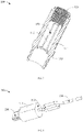
Fig. 1 is an exploded view of a line tube adapter assembly in one direction provided by an embodiment of the present invention; -
Fig. 2 is a schematic sectional view of the line tube adapter assembly ofFig. 1 taken along line A-A; -
Fig. 3 is a schematic sectional view of a housing ofFig. 1 in one direction; -
Fig. 4 is a schematic perspective view of a connector ofFig. 1 in one direction; -
Fig. 5 is a schematic perspective view of a line storage device ofFig. 1 in one direction; -
Fig. 6 is a schematic perspective view of a line tube adapter assembly in one direction provided by another embodiment of the present invention. - In order that the present invention may be readily understood, a more particular description of the invention will be rendered by reference to specific embodiments and the accompanying drawings. It should be noted that when an element is referred to as being "secured"/"fixed" to another element, it can be directly on the other element or one or more intermediate elements may be present between the elements. When one element is referred to as being "connected" to another element, it can be directly connected to the other element or one or more intermediate elements may be present between the elements. The terms "vertical", "horizontal", "left", "right", "inner", "outer", and the like are used herein for descriptive purposes only.
- Unless defined otherwise, all technical and scientific terms used in the description have the same meaning as commonly understood by one of ordinary skill in the art to which this invention belongs. The terms used in the description of the present invention are for the purpose of describing specific embodiments only and are not intended to be limiting of the present invention. As used in the description, the term "and/or" includes any and all combinations of one or more of the associated listed items.
- Further, the technical features involved in various embodiments of the present invention described below can be combined as long as they do not conflict with each other.
- In this description, "mounting" includes welding, screwing, clamping, gluing, etc. to fix or restrain a certain element or device in a specific position or place. The element or device may either be fixed in a specific position or place, or may be movable within a limited range. The element or device may or may not be detachable after being fixed or limited in the specific position or place, and is not limited in the embodiments of the present invention.
- Referring to
Figs. 1 to 2 that respectively showing an exploded view of a line tube adapter assembly in one direction provided by an embodiment of the present invention, and a schematic sectional view taken along line A-A, the line tube adapter assembly includes ahousing 100, aconnector 200, aline storage device 300, and aline tube 400. Theconnector 200 includes abase 210 and atransmission line 220; thebase 210 and theline storage device 300 are both accommodated in thehousing 100; one end of thebase 210 abuts against thehousing 100, and the other end abuts against theline storage device 300; thetransmission line 220 is connected to one end of thebase 210 close to theline storage device 300; one end of theline tube 400 extends into the interior of thehousing 100 and abuts against theline storage device 300; and at the same time, one end of theline tube 400 extending into thehousing 100 is fixedly connected to thehousing 100. - With regard to the above-mentioned
housing 100, reference is made toFig. 3 , which shows a schematic sectional view of thehousing 100 in one direction. And in conjunction withFigs. 1 and 2 , thehousing 100 has an overall hollow cylindrical structure, the inner side wall thereof is provided with aflange 110 formed by extending toward the center, and theflange 110 has a ring shape. Anaccommodation cavity 111 for accommodating the base 210 and theline storage device 300 is enclosed between theflange 110 and thehousing 100. One end of thehousing 100 is provided with aninternal thread 120, which is located in the above-mentionedaccommodation cavity 111 and is used for connecting with an external thread on theline tube 400. - With respect to the above-mentioned
connector 200, the reference is made toFig. 4 , which shows a schematic perspective view of theconnector 200 in one direction. In conjunction with -
Figs. 1-3 , theconnector 200 specifically includes abase 210, atransmission line 220, and acommunication port 230. Thebase 210 is accommodated in thehousing 100 in an approximately cylindrical shape adapted to the inner wall of thehousing 100, and thetransmission line 220 and thecommunication port 230 are respectively provided at both ends of the base 210 in the axial direction of thebase 210. One end of the base 210 away from thetransmission line 220 abuts against the above-mentionedflange 110, and the other end abuts against theline storage device 300. One end of thetransmission line 220 is connected to thebase 210 and the other end extends away from theflange 110 and into theline tube 400. Thecommunication port 230 for connecting with external equipment passes through theflange 110 and is connected with thetransmission line 220. - Further, in order to prevent the
transmission line 220 from being twisted in thehousing 100 or theline tube 400 due to the circumferential rotation of the assembledconnector 200 inside the housing, which makes thetransmission line 220 easily damaged by overwork, and to prevent thecommunication port 230 from being randomly rotated, the present line tube adapter assembly further includes a first limiting part and a second limiting part adapted to the first limiting part, wherein the first limiting part is located in the accommodation cavity and is provided on the inner wall of thehousing 100, and the second limiting part is provided on the outer wall of thebase 210, and the first limiting part and the second limiting part cooperate to fix theconnector 200 and thehousing 100 in the circumferential direction. - Specifically, referring to
Figs. 3 and 4 , a limitingprotrusion 130 is provided on the inner wall of thehousing 100 between theflange 110 and theinternal thread 130. The end face of one end of the limitingprotrusion 130 near the center of thehousing 100 is afirst plane 131, and thefirst plane 131 is parallel to the axis of thehousing 100, and thefirst plane 131 is the above-mentioned first limiting part. Correspondingly, the outer wall of thebase 210 is provided with asecond plane 211, and thesecond plane 211 is parallel to the axis of thebase 210, and thesecond plane 211 is the above-mentioned second limiting part. The distance between thefirst plane 131 and the axis of thehousing 100 is equal to the distance between thesecond plane 211 and the axis of thebase 210. When theconnector 200 is loaded into theaccommodation cavity 111, thesecond plane 211 is fitted with thefirst plane 131, and the remaining surface of the inner wall of thehousing 100 is adapted and fitted with the remaining surface of the outer wall of thebase 210. It is to be understood that thefirst plane 131 of the embodiment is indirectly formed on the inner wall of thehousing 100 through the limitingprotrusion 130. However, in other embodiments of the present invention, the first plane may be formed directly on the inner wall of thehousing 100, for example, the inner wall of thehousing 100 having a D-shape. - It should be understood that although the first limiting part and the second limiting part in the above-mentioned embodiments are both limiting planes, the present invention is not limited thereto; as long as the above-mentioned first limiting part and the second limiting part cooperate together so as to fix the installed connector 200 and housing 100 in the circumferential direction, it will do; for example: in some embodiments of the present invention, the first limiting part is a limiting protrusion extending from the inner wall of the housing to the center of the housing, and the second limiting part is a limiting groove extending from the outer wall of the base to the center of the base, wherein the limiting groove is adapted to the limiting protrusion, and the housing and the connector are circumferentially fixed by the matching of the limiting protrusion and the limiting groove; in further embodiments of the present invention, the first limiting part is a limiting groove extending from the inner wall of the housing towards a direction away from the center of the housing, and the second limiting part is a limiting protrusion extending from the outer wall of the base towards a direction away from the center of the base, wherein the limiting protrusion is adapted to the limiting groove, and the housing and the connector are circumferentially fixed by the matching of the limiting groove and the limiting protrusion.
- With regard to the
line storage device 300, the reference is made toFig. 5 , which shows a schematic perspective view of theline storage device 300 in one direction. In conjunction withFigs.1 to 4 at the same time, theline storage device 300 has an overall cylindrical structure, which is accommodated in theaccommodation cavity 111 in parallel, and one end of theline storage device 300 abuts against one end of the base 210 away from theflange 110, and the other end abuts against one end of theline tube 400 extending into thehousing 100. Theline storage device 300 is provided with anaccommodation space 310 in the form of a through-hole extending through theline storage device 300 from one end close to the base 210 to one end away from thebase 210. The outer wall of theline storage device 300 is further provided with aside opening 320 communicating with theaccommodation space 310, theside opening 320 extending from one end close to the base to one end away from the base. Theaccommodation space 310 always communicates with the side opening 320 from one end close to the base 210 to one end away from thebase 210. Theoverlong transmission line 220 in thehousing 100 and theline tube 400 can be accommodated in theaccommodation space 310 of theline storage device 300 by bending and folding (as shown inFig. 4 ), and theside opening 320 is provided to facilitate placing the bent and foldedtransmission line 220 in theaccommodation space 310. It is to be understood that in other embodiments of the present invention, theline storage device 300 may also be provided without a side opening, i.e. theline storage device 300 has an O-shape cross section parallel to the end face, and correspondingly, the bent and folded transmission line is accommodated in theline storage device 300 through the end part of theaccommodation space 310. - Further, in order to prevent the
transmission line 220 from being twisted in theaccommodation cavity 111 or theline tube 400 due to the circumferential rotation of the assembledline storage device 300 inside thehousing 100, which makes thetransmission line 220 easily damaged by overwork, the present line tube adapter assembly further comprises a third limiting part and a fourth limiting part adapted to the third limiting part, wherein the third limiting part is located in theaccommodation cavity 111 and is provided on the inner wall of thehousing 100, the fourth limiting part is provided on the outer wall of theline storage device 300, and the third limiting part and the fourth limiting part cooperate together to circumferentially fix theline storage device 300 and thehousing 100. - Specifically, referring to
Figs. 3 and5 , and in conjunction withFigs. 1, 2 , and4 , the inner wall of thehousing 100 is provided with a third plane, and the third plane is parallel to the axis of thehousing 100, and the third plane is the above-mentioned third limiting part. In this embodiment, the third plane is the above-mentionedfirst plane 131. Accordingly, the outer wall of theline storage device 300 is provided with afourth plane 330, and thefourth plane 330 is parallel to the axis of theline storage device 300, and thefourth plane 330 is the above-mentioned fourth limiting part. The distance between the third plane and the axis of thehousing 100 is equal to the distance between thefourth plane 330 and the axis of theline storage device 300. In the process of loading theline storage device 300 into thehousing 100, the above-mentionedfourth plane 330 is fitted with the third plane, and the remaining surface of the inner wall of thehousing 100 is adapted and fitted with the remaining surface of the outer wall of theline storage device 300. It will be understood that in other embodiments of the present invention, the third plane and thefirst plane 131 may also be two different planes. Preferably, thefourth plane 330 is provided at theside opening 320 of theline storage device 300, and theside opening 320 divides thefourth plane 330 into two parts. Thefourth plane 330, after being fitted with the third plane, can block thetransmission line 220 accommodated in theline storage device 300 from moving out of theline storage device 300 through theside opening 320. - With regard to the above-mentioned
line tube 400, referring toFigs. 1 and 2 , theline tube 400 has an overall cylindrical structure, one end of which extends into theaccommodation cavity 111 and abuts against one end of theline storage device 300 away from thebase 210. One end of theline tube 400 abutting against theline storage device 300 is provided with anexternal thread 410, and theline tube 400 is fixedly connected to thehousing 100 through theexternal thread 410 and the above-mentionedinternal thread 120. It should be understood that in other embodiments of the present invention, the external thread may also be provided on the housing, and correspondingly, the internal thread may be provided on the line tube, and the two may be fixed by matching the internal thread and external thread; in addition, theline tube 400 may be fixedly connected to thehousing 100 via a snap connection or the like. - The line tube adapter in the current market includes a housing, a connector, and a line tube. There are generally two fixing modes between the housing and the line tube, wherein one is to stamp the housing and the line tube into a coaxial close-fitting fixing through die stamping, and the other is to glue-fix the housing and the line tube through an adhesive such as glue. The mode of close-fitting fixing by stamping easily causes the housing or the line tube to extrude the transmission line to damage the transmission line; however, with regard to the glue-fixing mode, as time goes by, the product gradually ages, and the adhesive will fall off, and the line tube and the housing will separate, which will lead to the damage of the line tube adapter.
- However, the present invention provides a line tube adapter assembly, including a
housing 100, aconnector 200, aline storage device 300, and aline tube 400. On the one hand, the arrangement of theline storage device 300 can accommodate an overlong transmission line, so as to avoid damaging the transmission line during the assembly of thehousing 100 and theline tube 400; and on the other hand, both ends of theline storage device 300 abut against the base of theconnector 200 and the end part of theline tube 400, respectively, so that theconnector 200 is fixed to thehousing 100, and at the same time, one axial force is applied to theline tube 400 so that the axial force between theline tube 400 and thehousing 100 is sufficiently large, thereby enhancing the self-locking effect of the threaded connection of theline tube 400 and thehousing 100. Since the line tube adapter is not fixed by bonding, theline tube 400 of the line tube adapter will not separate from thehousing 100 by product aging. In addition, the arrangement of a threaded connection between theline tube 400 and thehousing 100 also facilitates the disassembly and assembly of the two, thereby facilitating the maintenance of the line tube adapter device. - Referring to
Fig. 6 , there is shown a schematic perspective view of a line tube adapter assembly in one direction provided by another embodiment of the present invention. In conjunction withFigs. 1-5 at the same time, the line tube adapter assembly of the present embodiment is generally the same as the line tube adapter assembly of the above-mentioned embodiment, with the major differences lying in that: theconnector 200 and theline storage device 300 in the first embodiment are independently arranged; however, the connector 200'and the line storage device 300' in the present embodiment are integrally formed and arranged, namely: one end of the line storage device 300'close to the connector 200' is fixedly connected to the base of the connector 200'. The integral arrangement of the connector 200' and the line storage device 300' facilitates the overall disassembly and assembly of the connector 200' and the line storage device 300', and the disassembly and assembly process of the line tube adapter assembly is simpler and more convenient. - It is to be understood that the line storage device 300' in the second embodiment may not be arranged with the above-mentioned side opening, that is, the cross section of the line storage device 300' parallel to the end face is O-shaped; the fourth plane may not be arranged at the side opening.
- Based on the same inventive concept, the present invention also provides an endoscope, including an endoscope body (not shown) and the above-mentioned line tube adapter assembly. Referring to
Figs. 1 to 6 , one end of the transmission line away from the flange is connected to the endoscope body. The endoscope may be applied in the industrial field or medical field. - According to the present invention, there is provided an endoscope line tube adapter assembly, including the above-mentioned line storage device. On the one hand, the line storage device is configured to accommodate an overlong transmission line, so that the transmission line connected to the above-mentioned endoscope body is not easily damaged; on the other hand, both ends of the line storage device respectively abut against the base of the connector and the end part of the line tube, so that the connector is fixed to the housing, and at the same time, one axial force is applied to the line tube, so that the axial force between the line tube and the housing is sufficiently large, thereby enhancing the self-locking effect of the threaded connection of the line tube and the housing. Since the line tube adapter is not fixed by bonding, the line tube and the housing of the line tube adapter in the endoscope will not separate by product aging.
- Finally, it should be noted that: the above embodiments are merely illustrative of the technical solutions of the present invention, rather than limiting the same; combinations of technical features in the above embodiments or in different embodiments are also possible within the concept of the invention, the steps may be implemented in any order, and there may be many other changes of different aspects of the present invention described above that are not provided in detail for the sake of brevity. Although the present invention has been described in detail with reference to the foregoing embodiments, those skilled in the art will appreciate that: the technical solutions disclosed in the above-mentioned embodiments can still be modified, or some of the technical features thereof can be replaced by equivalents; such modifications and substitutions do not depart the essence of the corresponding technical solutions from the scope of the technical solutions of various embodiments of the present invention.
Claims (14)
- A line tube adapter assembly, characterized by comprising:a housing provided with an accommodation cavity;a connector comprising a base and a transmission line, wherein the base is accommodated in the accommodation cavity, and the transmission line is connected to one end of the base;a line storage device accommodated in the accommodation cavity, wherein the line storage device is provided with an accommodation space configured to accommodate part of the transmission line;and a line tube provided at one end of the line storage device away from the base, the line tube being connected to the housing.
- The line tube adapter assembly of claim 1, characterized in that the accommodation space is a through-hole extending through the line storage device from one end close to the base to one end away from the base.
- The line tube adapter assembly of claim 2, characterized in that an outer wall of the line storage device is further provided with a side opening communicating with the accommodation space;
the accommodation space always communicates with the side opening from one end close to the base to one end away from the base. - The line tube adapter assembly of any one of claims 1 to 3, characterized in that the line storage device is integrally formed with the base.
- The line tube adapter assembly of claim 1, characterized by further comprising a first limiting part and a second limiting part adapted to the first limiting part, wherein the first limiting part is located in the accommodation cavity and provided on an inner wall of the housing, and the second limiting part is provided on an outer wall of the base, the first limiting part and the second limiting part matching to circumferentially fix the connector and the housing.
- The line tube adapter assembly of claim 5, characterized in that the inner wall of the housing is provided with a first plane, the first plane being the first limiting part, and the outer wall of the base is provided with a second plane, the second plane being the second limiting part, and the first plane is fitted with the second plane.
- The line tube adapter assembly of claim 5, characterized in thatthe first limiting part is a limiting protrusion extending from the inner wall of the housing to a center of the housing, the second limiting part is a limiting groove extending from the outer wall of the base to the center of the base and adapted to the limiting protrusion, and circumferential fixing is achieved between the housing and the connector through the matching of the limiting protrusion and the limiting groove; alternatively,the first limiting part is a limiting groove extending from the inner wall of the housing to a direction away from the center of the housing, the second limiting part is a limiting protrusion extending from the outer wall of the base to a direction away from the center of the base and adapted to the limiting groove, and circumferential fixing is achieved between the housing and the connector through matching of the limiting groove and the limiting protrusion.
- The line tube adapter assembly of claim 1, characterized by further comprising a third limiting part, and a fourth limiting part adapted to the third limiting part, wherein the third limiting part is located in the accommodation cavity and is provided on an inner wall of the housing, the fourth limiting part is provided on an outer wall of the line storage device, and the third limiting part and the fourth limiting part match to circumferentially fix the line storage device and the housing.
- The line tube adapter assembly of claim 8, characterized in that the inner wall of the housing is provided with a third plane, the third plane being the third limiting part, and the outer wall of the line storage device is provided with a fourth plane, the fourth plane being the fourth limiting part, and the third plane is fitted with the fourth plane.
- The line tube adapter assembly of claim 9, characterized in that the accommodation space is a through-hole extending through the line storage device from one end close to the base to one end away from the base.the outer wall of the line storage device is further provided with a side opening communicating with the accommodation space, and the accommodation space always communicates with the side opening from one end close to the base to one end away from the base;the side opening divides the fourth plane into two parts.
- The line tube adapter assembly of claim 1, characterized in that the connector further comprises a communication port provided at one end of the base away from the transmission line, the communication port being connected to the transmission line.
- The line tube adapter assembly of claim 1, characterized in that the housing is threadedly connected to the line tube.
- The line tube adapter assembly of claim 12, characterized in that the inner side wall of the housing is provided with a centrally extending flange, one end of the base away from the transmission line abutting against the flange, one end of the base away from the flange abutting against or being fixed to the line storage device, and one end of the line tube extending into the accommodation cavity, abutting against the line storage device, and being threadedly connected to the housing.
- An endoscope, characterized by comprising an endoscope body, and the line tube adapter assembly according to any one of claims 1 to 13, wherein the transmission line is connected to the endoscope body.
Applications Claiming Priority (2)
| Application Number | Priority Date | Filing Date | Title |
|---|---|---|---|
| CN201910842095.4A CN110444978B (en) | 2019-09-06 | 2019-09-06 | Wire tube adapter assembly and endoscope |
| PCT/CN2020/113581 WO2021043282A1 (en) | 2019-09-06 | 2020-09-04 | Line tube adapter assembly and endoscope |
Publications (3)
| Publication Number | Publication Date |
|---|---|
| EP4007086A1 true EP4007086A1 (en) | 2022-06-01 |
| EP4007086A4 EP4007086A4 (en) | 2022-08-31 |
| EP4007086B1 EP4007086B1 (en) | 2024-07-17 |
Family
ID=68439479
Family Applications (1)
| Application Number | Title | Priority Date | Filing Date |
|---|---|---|---|
| EP20861370.3A Active EP4007086B1 (en) | 2019-09-06 | 2020-09-04 | Line tube adapter assembly and endoscope |
Country Status (4)
| Country | Link |
|---|---|
| US (1) | US12169272B2 (en) |
| EP (1) | EP4007086B1 (en) |
| CN (1) | CN110444978B (en) |
| WO (1) | WO2021043282A1 (en) |
Families Citing this family (2)
| Publication number | Priority date | Publication date | Assignee | Title |
|---|---|---|---|---|
| CN110444978B (en) | 2019-09-06 | 2024-07-26 | 深圳市道通科技股份有限公司 | Wire tube adapter assembly and endoscope |
| CN111012284B (en) * | 2019-11-22 | 2022-08-26 | 浙江百安医疗科技有限公司 | Endoscope and method for operating the same |
Family Cites Families (40)
| Publication number | Priority date | Publication date | Assignee | Title |
|---|---|---|---|---|
| US3219961A (en) * | 1963-02-04 | 1965-11-23 | Switchcraft | Electrical connector |
| DE4404260A1 (en) * | 1994-02-10 | 1995-08-17 | W W Fischer Sa | Electric plug connector |
| US20110034769A1 (en) * | 1997-10-06 | 2011-02-10 | Micro-Imaging Solutions Llc | Reduced area imaging device incorporated within wireless endoscopic devices |
| EP1834571A4 (en) * | 2005-01-07 | 2012-12-05 | Olympus Medical Systems Corp | INSERTION UNIT FOR ENDOSCOPE |
| WO2006073186A1 (en) * | 2005-01-07 | 2006-07-13 | Olympus Medical Systems Corp. | Endoscope-use insertion unit |
| JP2008237812A (en) * | 2007-03-29 | 2008-10-09 | Olympus Medical Systems Corp | Multi-joint bending mechanism and medical device with multi-joint bending mechanism |
| JP4987790B2 (en) * | 2008-04-15 | 2012-07-25 | オリンパスメディカルシステムズ株式会社 | Imaging device |
| WO2012077626A1 (en) * | 2010-12-06 | 2012-06-14 | オリンパスメディカルシステムズ株式会社 | Connector |
| CN201986304U (en) * | 2010-12-31 | 2011-09-21 | 奇盟国际有限公司 | The hidden structure of the combination of 3C products and transmission lines |
| CN202231202U (en) * | 2011-09-01 | 2012-05-23 | 富士康(昆山)电脑接插件有限公司 | Adapter |
| WO2013084547A1 (en) * | 2011-12-07 | 2013-06-13 | オリンパスメディカルシステムズ株式会社 | Electronic endoscope |
| WO2013114661A1 (en) * | 2012-01-31 | 2013-08-08 | オリンパスメディカルシステムズ株式会社 | Endoscope |
| KR101946974B1 (en) * | 2012-12-12 | 2019-02-12 | 엘지이노텍 주식회사 | Tuner jack and tuner module including the same |
| JP5690455B1 (en) * | 2013-04-16 | 2015-03-25 | オリンパスメディカルシステムズ株式会社 | Board connection structure |
| US10499794B2 (en) * | 2013-05-09 | 2019-12-10 | Endochoice, Inc. | Operational interface in a multi-viewing element endoscope |
| CN105222026B (en) * | 2014-06-26 | 2018-04-24 | 欧普照明股份有限公司 | A kind of guide tracked pendent lamp |
| JP6215806B2 (en) * | 2014-09-29 | 2017-10-18 | 富士フイルム株式会社 | Endoscope |
| JP6058226B2 (en) * | 2014-12-25 | 2017-01-11 | オリンパス株式会社 | Endoscope |
| EP3285634A4 (en) * | 2015-04-20 | 2019-01-09 | Medrobotics Corporation | Articulated robotic probes |
| CN104864299B (en) * | 2015-06-04 | 2017-08-25 | 欧普照明股份有限公司 | A kind of strip light and strip light combination with wire harness adapter assembly |
| KR101699229B1 (en) * | 2015-09-03 | 2017-01-25 | 부산대학교 산학협력단 | Light guide injection device |
| CN106610524B (en) * | 2015-10-23 | 2019-08-16 | 宁波舜宇光电信息有限公司 | Endoscope and its camera assembly |
| WO2017086107A1 (en) * | 2015-11-16 | 2017-05-26 | オリンパス株式会社 | Device for insertion of treatment instrument |
| CN108366710B (en) * | 2015-11-20 | 2020-08-11 | 奥林巴斯株式会社 | endoscope system |
| CN108348140B (en) * | 2016-06-07 | 2020-10-30 | 奥林巴斯株式会社 | Endoscopic systems and endoscopes |
| US9966696B2 (en) * | 2016-09-29 | 2018-05-08 | Huidong Songyi Manufactory Co. Ltd. | Two connector assemblies coupled to each other and an elastic conductive metal sheet connected to a receptacle tube containing one of the assemblies |
| CN206135166U (en) * | 2016-11-19 | 2017-04-26 | 中国医科大学附属第一医院 | Apply to data acquisition line of urine sample medical treatment testing instruments |
| JP6330117B1 (en) * | 2016-12-20 | 2018-05-23 | オリンパス株式会社 | Board mounting structure |
| JP6837217B2 (en) * | 2017-01-26 | 2021-03-03 | パナソニックIpマネジメント株式会社 | Lighting device for endoscopes |
| JP6853076B2 (en) * | 2017-03-13 | 2021-03-31 | ソニー・オリンパスメディカルソリューションズ株式会社 | Endoscope device |
| US20180280046A1 (en) * | 2017-03-30 | 2018-10-04 | Acclarent, Inc. | Guidewire with optics tube containing core wire |
| CN108802910A (en) * | 2017-04-28 | 2018-11-13 | 中天海洋系统有限公司 | Optical connector |
| CN207134515U (en) * | 2017-05-14 | 2018-03-23 | 朱立立 | A kind of cellular phone data line protective cover of energy take-up |
| CN207947456U (en) | 2017-06-16 | 2018-10-09 | 惠东淞艺工艺品有限公司 | A kind of electric connector for artificial tree |
| CN207505339U (en) * | 2017-11-08 | 2018-06-15 | 四川信息职业技术学院 | For the anti-static device of electronic and electrical equipment |
| CN208508090U (en) * | 2018-09-10 | 2019-02-15 | 深圳市坚果皮科技有限公司 | A data cable structure that is easy to store and carry |
| CN109254394A (en) * | 2018-10-24 | 2019-01-22 | 深圳市古安泰自动化技术有限公司 | Endoscopic system |
| CN209016373U (en) * | 2018-12-24 | 2019-06-21 | 深圳市聚胜得电子有限公司 | A kind of smart phone patchcord |
| CN110444978B (en) * | 2019-09-06 | 2024-07-26 | 深圳市道通科技股份有限公司 | Wire tube adapter assembly and endoscope |
| CN210326406U (en) * | 2019-09-06 | 2020-04-14 | 深圳市道通科技股份有限公司 | Spool switching subassembly and endoscope |
-
2019
- 2019-09-06 CN CN201910842095.4A patent/CN110444978B/en active Active
-
2020
- 2020-09-04 EP EP20861370.3A patent/EP4007086B1/en active Active
- 2020-09-04 WO PCT/CN2020/113581 patent/WO2021043282A1/en not_active Ceased
-
2022
- 2022-02-22 US US17/651,980 patent/US12169272B2/en active Active
Also Published As
| Publication number | Publication date |
|---|---|
| EP4007086A4 (en) | 2022-08-31 |
| EP4007086B1 (en) | 2024-07-17 |
| CN110444978A (en) | 2019-11-12 |
| WO2021043282A1 (en) | 2021-03-11 |
| CN110444978B (en) | 2024-07-26 |
| US12169272B2 (en) | 2024-12-17 |
| US20220171179A1 (en) | 2022-06-02 |
Similar Documents
| Publication | Publication Date | Title |
|---|---|---|
| US12169272B2 (en) | Line tube adapter assembly and endoscope | |
| US7689090B2 (en) | Cable sleeve for the structured storage and handling of optical waveguides guided in optical waveguide cables | |
| US7264506B2 (en) | Terminal-movable connector | |
| EP2617613A2 (en) | Wiper connector and bolt-stabilizing sleeve adaptor | |
| US8960973B1 (en) | Splice enclosure for luminaires | |
| JP2009528095A (en) | Two-piece double syringe | |
| AU2012385404A1 (en) | Electronic cigarette | |
| US20170077636A1 (en) | Connector | |
| WO2011113055A1 (en) | Portable universal serial bus (usb) cable assembly | |
| KR20170012948A (en) | Assembling frame structure | |
| CN210326406U (en) | Spool switching subassembly and endoscope | |
| EA034782B1 (en) | Extension cord, socket and cover of a socket | |
| US20080242154A1 (en) | Powered, Mobile Electronics Mount | |
| CN210779187U (en) | Cable adapter of monitor | |
| JPH06504142A (en) | Multipurpose fiber optic connector | |
| CN207217904U (en) | A kind of structure of coaxial connector | |
| WO2020092480A1 (en) | Adapter for cable gland and cable gland unit | |
| US20160211605A1 (en) | Electrical connector having a seal retainer | |
| ES2685320T3 (en) | Multi-device block equipped with wall fixing means | |
| CN211210161U (en) | Aluminum profile frame structure for liquid crystal display screen | |
| CN212587827U (en) | Self-assembly changeover plug | |
| CN211351682U (en) | Novel cable connection device | |
| US12601877B2 (en) | Multipurpose fiber-optic connector and fiber-optic adapter | |
| US10214309B2 (en) | Plastic tube designed for pressing out a liquid to pasty mass | |
| CN109262224A (en) | Cooperate the tooling accessory of toothed wheel installation |
Legal Events
| Date | Code | Title | Description |
|---|---|---|---|
| STAA | Information on the status of an ep patent application or granted ep patent |
Free format text: STATUS: THE INTERNATIONAL PUBLICATION HAS BEEN MADE |
|
| PUAI | Public reference made under article 153(3) epc to a published international application that has entered the european phase |
Free format text: ORIGINAL CODE: 0009012 |
|
| STAA | Information on the status of an ep patent application or granted ep patent |
Free format text: STATUS: REQUEST FOR EXAMINATION WAS MADE |
|
| 17P | Request for examination filed |
Effective date: 20220224 |
|
| AK | Designated contracting states |
Kind code of ref document: A1 Designated state(s): AL AT BE BG CH CY CZ DE DK EE ES FI FR GB GR HR HU IE IS IT LI LT LU LV MC MK MT NL NO PL PT RO RS SE SI SK SM TR |
|
| REG | Reference to a national code |
Ref legal event code: R079 Free format text: PREVIOUS MAIN CLASS: H01R0031060000 Ipc: H01R0013720000 Ref country code: DE Ref legal event code: R079 Ref document number: 602020034273 Country of ref document: DE Free format text: PREVIOUS MAIN CLASS: H01R0031060000 Ipc: H01R0013720000 |
|
| A4 | Supplementary search report drawn up and despatched |
Effective date: 20220801 |
|
| RIC1 | Information provided on ipc code assigned before grant |
Ipc: A61B 1/00 20060101ALI20220726BHEP Ipc: G02B 23/24 20060101ALI20220726BHEP Ipc: H01R 13/72 20060101AFI20220726BHEP |
|
| DAV | Request for validation of the european patent (deleted) | ||
| DAX | Request for extension of the european patent (deleted) | ||
| GRAP | Despatch of communication of intention to grant a patent |
Free format text: ORIGINAL CODE: EPIDOSNIGR1 |
|
| STAA | Information on the status of an ep patent application or granted ep patent |
Free format text: STATUS: GRANT OF PATENT IS INTENDED |
|
| INTG | Intention to grant announced |
Effective date: 20240508 |
|
| GRAS | Grant fee paid |
Free format text: ORIGINAL CODE: EPIDOSNIGR3 |
|
| GRAA | (expected) grant |
Free format text: ORIGINAL CODE: 0009210 |
|
| STAA | Information on the status of an ep patent application or granted ep patent |
Free format text: STATUS: THE PATENT HAS BEEN GRANTED |
|
| AK | Designated contracting states |
Kind code of ref document: B1 Designated state(s): AL AT BE BG CH CY CZ DE DK EE ES FI FR GB GR HR HU IE IS IT LI LT LU LV MC MK MT NL NO PL PT RO RS SE SI SK SM TR |
|
| REG | Reference to a national code |
Ref country code: CH Ref legal event code: EP |
|
| REG | Reference to a national code |
Ref country code: DE Ref legal event code: R096 Ref document number: 602020034273 Country of ref document: DE |
|
| REG | Reference to a national code |
Ref country code: IE Ref legal event code: FG4D |
|
| REG | Reference to a national code |
Ref country code: LT Ref legal event code: MG9D |
|
| REG | Reference to a national code |
Ref country code: NL Ref legal event code: MP Effective date: 20240717 |
|
| PG25 | Lapsed in a contracting state [announced via postgrant information from national office to epo] |
Ref country code: PT Free format text: LAPSE BECAUSE OF FAILURE TO SUBMIT A TRANSLATION OF THE DESCRIPTION OR TO PAY THE FEE WITHIN THE PRESCRIBED TIME-LIMIT Effective date: 20241118 |
|
| REG | Reference to a national code |
Ref country code: AT Ref legal event code: MK05 Ref document number: 1705043 Country of ref document: AT Kind code of ref document: T Effective date: 20240717 |
|
| PG25 | Lapsed in a contracting state [announced via postgrant information from national office to epo] |
Ref country code: NL Free format text: LAPSE BECAUSE OF FAILURE TO SUBMIT A TRANSLATION OF THE DESCRIPTION OR TO PAY THE FEE WITHIN THE PRESCRIBED TIME-LIMIT Effective date: 20240717 |
|
| PG25 | Lapsed in a contracting state [announced via postgrant information from national office to epo] |
Ref country code: PT Free format text: LAPSE BECAUSE OF FAILURE TO SUBMIT A TRANSLATION OF THE DESCRIPTION OR TO PAY THE FEE WITHIN THE PRESCRIBED TIME-LIMIT Effective date: 20241118 Ref country code: NL Free format text: LAPSE BECAUSE OF FAILURE TO SUBMIT A TRANSLATION OF THE DESCRIPTION OR TO PAY THE FEE WITHIN THE PRESCRIBED TIME-LIMIT Effective date: 20240717 |
|
| PG25 | Lapsed in a contracting state [announced via postgrant information from national office to epo] |
Ref country code: NO Free format text: LAPSE BECAUSE OF FAILURE TO SUBMIT A TRANSLATION OF THE DESCRIPTION OR TO PAY THE FEE WITHIN THE PRESCRIBED TIME-LIMIT Effective date: 20241017 |
|
| PG25 | Lapsed in a contracting state [announced via postgrant information from national office to epo] |
Ref country code: FI Free format text: LAPSE BECAUSE OF FAILURE TO SUBMIT A TRANSLATION OF THE DESCRIPTION OR TO PAY THE FEE WITHIN THE PRESCRIBED TIME-LIMIT Effective date: 20240717 Ref country code: PL Free format text: LAPSE BECAUSE OF FAILURE TO SUBMIT A TRANSLATION OF THE DESCRIPTION OR TO PAY THE FEE WITHIN THE PRESCRIBED TIME-LIMIT Effective date: 20240717 Ref country code: GR Free format text: LAPSE BECAUSE OF FAILURE TO SUBMIT A TRANSLATION OF THE DESCRIPTION OR TO PAY THE FEE WITHIN THE PRESCRIBED TIME-LIMIT Effective date: 20241018 |
|
| PG25 | Lapsed in a contracting state [announced via postgrant information from national office to epo] |
Ref country code: BG Free format text: LAPSE BECAUSE OF FAILURE TO SUBMIT A TRANSLATION OF THE DESCRIPTION OR TO PAY THE FEE WITHIN THE PRESCRIBED TIME-LIMIT Effective date: 20240717 |
|
| PG25 | Lapsed in a contracting state [announced via postgrant information from national office to epo] |
Ref country code: LV Free format text: LAPSE BECAUSE OF FAILURE TO SUBMIT A TRANSLATION OF THE DESCRIPTION OR TO PAY THE FEE WITHIN THE PRESCRIBED TIME-LIMIT Effective date: 20240717 |
|
| PG25 | Lapsed in a contracting state [announced via postgrant information from national office to epo] |
Ref country code: IS Free format text: LAPSE BECAUSE OF FAILURE TO SUBMIT A TRANSLATION OF THE DESCRIPTION OR TO PAY THE FEE WITHIN THE PRESCRIBED TIME-LIMIT Effective date: 20241117 Ref country code: AT Free format text: LAPSE BECAUSE OF FAILURE TO SUBMIT A TRANSLATION OF THE DESCRIPTION OR TO PAY THE FEE WITHIN THE PRESCRIBED TIME-LIMIT Effective date: 20240717 |
|
| PG25 | Lapsed in a contracting state [announced via postgrant information from national office to epo] |
Ref country code: HR Free format text: LAPSE BECAUSE OF FAILURE TO SUBMIT A TRANSLATION OF THE DESCRIPTION OR TO PAY THE FEE WITHIN THE PRESCRIBED TIME-LIMIT Effective date: 20240717 |
|
| PG25 | Lapsed in a contracting state [announced via postgrant information from national office to epo] |
Ref country code: ES Free format text: LAPSE BECAUSE OF FAILURE TO SUBMIT A TRANSLATION OF THE DESCRIPTION OR TO PAY THE FEE WITHIN THE PRESCRIBED TIME-LIMIT Effective date: 20240717 Ref country code: RS Free format text: LAPSE BECAUSE OF FAILURE TO SUBMIT A TRANSLATION OF THE DESCRIPTION OR TO PAY THE FEE WITHIN THE PRESCRIBED TIME-LIMIT Effective date: 20241017 |
|
| PG25 | Lapsed in a contracting state [announced via postgrant information from national office to epo] |
Ref country code: RS Free format text: LAPSE BECAUSE OF FAILURE TO SUBMIT A TRANSLATION OF THE DESCRIPTION OR TO PAY THE FEE WITHIN THE PRESCRIBED TIME-LIMIT Effective date: 20241017 Ref country code: PL Free format text: LAPSE BECAUSE OF FAILURE TO SUBMIT A TRANSLATION OF THE DESCRIPTION OR TO PAY THE FEE WITHIN THE PRESCRIBED TIME-LIMIT Effective date: 20240717 Ref country code: NO Free format text: LAPSE BECAUSE OF FAILURE TO SUBMIT A TRANSLATION OF THE DESCRIPTION OR TO PAY THE FEE WITHIN THE PRESCRIBED TIME-LIMIT Effective date: 20241017 Ref country code: LV Free format text: LAPSE BECAUSE OF FAILURE TO SUBMIT A TRANSLATION OF THE DESCRIPTION OR TO PAY THE FEE WITHIN THE PRESCRIBED TIME-LIMIT Effective date: 20240717 Ref country code: IS Free format text: LAPSE BECAUSE OF FAILURE TO SUBMIT A TRANSLATION OF THE DESCRIPTION OR TO PAY THE FEE WITHIN THE PRESCRIBED TIME-LIMIT Effective date: 20241117 Ref country code: HR Free format text: LAPSE BECAUSE OF FAILURE TO SUBMIT A TRANSLATION OF THE DESCRIPTION OR TO PAY THE FEE WITHIN THE PRESCRIBED TIME-LIMIT Effective date: 20240717 Ref country code: GR Free format text: LAPSE BECAUSE OF FAILURE TO SUBMIT A TRANSLATION OF THE DESCRIPTION OR TO PAY THE FEE WITHIN THE PRESCRIBED TIME-LIMIT Effective date: 20241018 Ref country code: FI Free format text: LAPSE BECAUSE OF FAILURE TO SUBMIT A TRANSLATION OF THE DESCRIPTION OR TO PAY THE FEE WITHIN THE PRESCRIBED TIME-LIMIT Effective date: 20240717 Ref country code: ES Free format text: LAPSE BECAUSE OF FAILURE TO SUBMIT A TRANSLATION OF THE DESCRIPTION OR TO PAY THE FEE WITHIN THE PRESCRIBED TIME-LIMIT Effective date: 20240717 Ref country code: BG Free format text: LAPSE BECAUSE OF FAILURE TO SUBMIT A TRANSLATION OF THE DESCRIPTION OR TO PAY THE FEE WITHIN THE PRESCRIBED TIME-LIMIT Effective date: 20240717 Ref country code: AT Free format text: LAPSE BECAUSE OF FAILURE TO SUBMIT A TRANSLATION OF THE DESCRIPTION OR TO PAY THE FEE WITHIN THE PRESCRIBED TIME-LIMIT Effective date: 20240717 |
|
| PG25 | Lapsed in a contracting state [announced via postgrant information from national office to epo] |
Ref country code: DK Free format text: LAPSE BECAUSE OF FAILURE TO SUBMIT A TRANSLATION OF THE DESCRIPTION OR TO PAY THE FEE WITHIN THE PRESCRIBED TIME-LIMIT Effective date: 20240717 Ref country code: RO Free format text: LAPSE BECAUSE OF FAILURE TO SUBMIT A TRANSLATION OF THE DESCRIPTION OR TO PAY THE FEE WITHIN THE PRESCRIBED TIME-LIMIT Effective date: 20240717 Ref country code: SM Free format text: LAPSE BECAUSE OF FAILURE TO SUBMIT A TRANSLATION OF THE DESCRIPTION OR TO PAY THE FEE WITHIN THE PRESCRIBED TIME-LIMIT Effective date: 20240717 |
|
| REG | Reference to a national code |
Ref country code: DE Ref legal event code: R097 Ref document number: 602020034273 Country of ref document: DE |
|
| PG25 | Lapsed in a contracting state [announced via postgrant information from national office to epo] |
Ref country code: MC Free format text: LAPSE BECAUSE OF FAILURE TO SUBMIT A TRANSLATION OF THE DESCRIPTION OR TO PAY THE FEE WITHIN THE PRESCRIBED TIME-LIMIT Effective date: 20240717 Ref country code: EE Free format text: LAPSE BECAUSE OF FAILURE TO SUBMIT A TRANSLATION OF THE DESCRIPTION OR TO PAY THE FEE WITHIN THE PRESCRIBED TIME-LIMIT Effective date: 20240717 |
|
| PG25 | Lapsed in a contracting state [announced via postgrant information from national office to epo] |
Ref country code: CZ Free format text: LAPSE BECAUSE OF FAILURE TO SUBMIT A TRANSLATION OF THE DESCRIPTION OR TO PAY THE FEE WITHIN THE PRESCRIBED TIME-LIMIT Effective date: 20240717 |
|
| PG25 | Lapsed in a contracting state [announced via postgrant information from national office to epo] |
Ref country code: SK Free format text: LAPSE BECAUSE OF FAILURE TO SUBMIT A TRANSLATION OF THE DESCRIPTION OR TO PAY THE FEE WITHIN THE PRESCRIBED TIME-LIMIT Effective date: 20240717 |
|
| REG | Reference to a national code |
Ref country code: CH Ref legal event code: PL |
|
| PG25 | Lapsed in a contracting state [announced via postgrant information from national office to epo] |
Ref country code: LU Free format text: LAPSE BECAUSE OF NON-PAYMENT OF DUE FEES Effective date: 20240904 |
|
| PLBE | No opposition filed within time limit |
Free format text: ORIGINAL CODE: 0009261 |
|
| STAA | Information on the status of an ep patent application or granted ep patent |
Free format text: STATUS: NO OPPOSITION FILED WITHIN TIME LIMIT |
|
| 26N | No opposition filed |
Effective date: 20250422 |
|
| REG | Reference to a national code |
Ref country code: BE Ref legal event code: MM Effective date: 20240930 |
|
| PG25 | Lapsed in a contracting state [announced via postgrant information from national office to epo] |
Ref country code: BE Free format text: LAPSE BECAUSE OF NON-PAYMENT OF DUE FEES Effective date: 20240930 |
|
| PG25 | Lapsed in a contracting state [announced via postgrant information from national office to epo] |
Ref country code: CH Free format text: LAPSE BECAUSE OF NON-PAYMENT OF DUE FEES Effective date: 20240930 |
|
| PG25 | Lapsed in a contracting state [announced via postgrant information from national office to epo] |
Ref country code: IE Free format text: LAPSE BECAUSE OF NON-PAYMENT OF DUE FEES Effective date: 20240904 |
|
| PG25 | Lapsed in a contracting state [announced via postgrant information from national office to epo] |
Ref country code: SE Free format text: LAPSE BECAUSE OF FAILURE TO SUBMIT A TRANSLATION OF THE DESCRIPTION OR TO PAY THE FEE WITHIN THE PRESCRIBED TIME-LIMIT Effective date: 20240717 |
|
| PGFP | Annual fee paid to national office [announced via postgrant information from national office to epo] |
Ref country code: DE Payment date: 20250919 Year of fee payment: 6 |
|
| PGFP | Annual fee paid to national office [announced via postgrant information from national office to epo] |
Ref country code: GB Payment date: 20250923 Year of fee payment: 6 |
|
| PGFP | Annual fee paid to national office [announced via postgrant information from national office to epo] |
Ref country code: FR Payment date: 20250924 Year of fee payment: 6 |
|
| PG25 | Lapsed in a contracting state [announced via postgrant information from national office to epo] |
Ref country code: CY Free format text: LAPSE BECAUSE OF FAILURE TO SUBMIT A TRANSLATION OF THE DESCRIPTION OR TO PAY THE FEE WITHIN THE PRESCRIBED TIME-LIMIT; INVALID AB INITIO Effective date: 20200904 Ref country code: IT Free format text: LAPSE BECAUSE OF FAILURE TO SUBMIT A TRANSLATION OF THE DESCRIPTION OR TO PAY THE FEE WITHIN THE PRESCRIBED TIME-LIMIT Effective date: 20240717 |
|
| PG25 | Lapsed in a contracting state [announced via postgrant information from national office to epo] |
Ref country code: HU Free format text: LAPSE BECAUSE OF FAILURE TO SUBMIT A TRANSLATION OF THE DESCRIPTION OR TO PAY THE FEE WITHIN THE PRESCRIBED TIME-LIMIT; INVALID AB INITIO Effective date: 20200904 |