EP4007072A1 - Terminal and terminal fixing structure - Google Patents
Terminal and terminal fixing structure Download PDFInfo
- Publication number
- EP4007072A1 EP4007072A1 EP21209534.3A EP21209534A EP4007072A1 EP 4007072 A1 EP4007072 A1 EP 4007072A1 EP 21209534 A EP21209534 A EP 21209534A EP 4007072 A1 EP4007072 A1 EP 4007072A1
- Authority
- EP
- European Patent Office
- Prior art keywords
- terminal
- bolt
- seat
- rotation stop
- flat surface
- Prior art date
- Legal status (The legal status is an assumption and is not a legal conclusion. Google has not performed a legal analysis and makes no representation as to the accuracy of the status listed.)
- Granted
Links
- 238000003780 insertion Methods 0.000 claims description 3
- 230000037431 insertion Effects 0.000 claims description 3
- 238000006073 displacement reaction Methods 0.000 description 9
- 238000000034 method Methods 0.000 description 6
- 230000000694 effects Effects 0.000 description 3
- 210000000078 claw Anatomy 0.000 description 2
- 238000012986 modification Methods 0.000 description 2
- 230000004048 modification Effects 0.000 description 2
- 230000002093 peripheral effect Effects 0.000 description 2
- 238000013459 approach Methods 0.000 description 1
- 238000005452 bending Methods 0.000 description 1
- 230000008595 infiltration Effects 0.000 description 1
- 238000001764 infiltration Methods 0.000 description 1
- 238000004519 manufacturing process Methods 0.000 description 1
- 239000000463 material Substances 0.000 description 1
- XLYOFNOQVPJJNP-UHFFFAOYSA-N water Substances O XLYOFNOQVPJJNP-UHFFFAOYSA-N 0.000 description 1
Images


Classifications
-
- H—ELECTRICITY
- H01—ELECTRIC ELEMENTS
- H01R—ELECTRICALLY-CONDUCTIVE CONNECTIONS; STRUCTURAL ASSOCIATIONS OF A PLURALITY OF MUTUALLY-INSULATED ELECTRICAL CONNECTING ELEMENTS; COUPLING DEVICES; CURRENT COLLECTORS
- H01R4/00—Electrically-conductive connections between two or more conductive members in direct contact, i.e. touching one another; Means for effecting or maintaining such contact; Electrically-conductive connections having two or more spaced connecting locations for conductors and using contact members penetrating insulation
- H01R4/28—Clamped connections, spring connections
- H01R4/30—Clamped connections, spring connections utilising a screw or nut clamping member
- H01R4/307—Clamped connections, spring connections utilising a screw or nut clamping member characterised by the thread of the screw or nut
-
- H—ELECTRICITY
- H01—ELECTRIC ELEMENTS
- H01R—ELECTRICALLY-CONDUCTIVE CONNECTIONS; STRUCTURAL ASSOCIATIONS OF A PLURALITY OF MUTUALLY-INSULATED ELECTRICAL CONNECTING ELEMENTS; COUPLING DEVICES; CURRENT COLLECTORS
- H01R13/00—Details of coupling devices of the kinds covered by groups H01R12/70 or H01R24/00 - H01R33/00
- H01R13/02—Contact members
-
- F—MECHANICAL ENGINEERING; LIGHTING; HEATING; WEAPONS; BLASTING
- F16—ENGINEERING ELEMENTS AND UNITS; GENERAL MEASURES FOR PRODUCING AND MAINTAINING EFFECTIVE FUNCTIONING OF MACHINES OR INSTALLATIONS; THERMAL INSULATION IN GENERAL
- F16B—DEVICES FOR FASTENING OR SECURING CONSTRUCTIONAL ELEMENTS OR MACHINE PARTS TOGETHER, e.g. NAILS, BOLTS, CIRCLIPS, CLAMPS, CLIPS OR WEDGES; JOINTS OR JOINTING
- F16B35/00—Screw-bolts; Stay-bolts; Screw-threaded studs; Screws; Set screws
- F16B35/04—Screw-bolts; Stay-bolts; Screw-threaded studs; Screws; Set screws with specially-shaped head or shaft in order to fix the bolt on or in an object
- F16B35/06—Specially-shaped heads
-
- F—MECHANICAL ENGINEERING; LIGHTING; HEATING; WEAPONS; BLASTING
- F16—ENGINEERING ELEMENTS AND UNITS; GENERAL MEASURES FOR PRODUCING AND MAINTAINING EFFECTIVE FUNCTIONING OF MACHINES OR INSTALLATIONS; THERMAL INSULATION IN GENERAL
- F16B—DEVICES FOR FASTENING OR SECURING CONSTRUCTIONAL ELEMENTS OR MACHINE PARTS TOGETHER, e.g. NAILS, BOLTS, CIRCLIPS, CLAMPS, CLIPS OR WEDGES; JOINTS OR JOINTING
- F16B39/00—Locking of screws, bolts or nuts
- F16B39/22—Locking of screws, bolts or nuts in which the locking takes place during screwing down or tightening
- F16B39/28—Locking of screws, bolts or nuts in which the locking takes place during screwing down or tightening by special members on, or shape of, the nut or bolt
- F16B39/282—Locking by means of special shape of work-engaging surfaces, e.g. notched or toothed nuts
-
- H—ELECTRICITY
- H01—ELECTRIC ELEMENTS
- H01R—ELECTRICALLY-CONDUCTIVE CONNECTIONS; STRUCTURAL ASSOCIATIONS OF A PLURALITY OF MUTUALLY-INSULATED ELECTRICAL CONNECTING ELEMENTS; COUPLING DEVICES; CURRENT COLLECTORS
- H01R11/00—Individual connecting elements providing two or more spaced connecting locations for conductive members which are, or may be, thereby interconnected, e.g. end pieces for wires or cables supported by the wire or cable and having means for facilitating electrical connection to some other wire, terminal, or conductive member, blocks of binding posts
- H01R11/11—End pieces or tapping pieces for wires, supported by the wire and for facilitating electrical connection to some other wire, terminal or conductive member
- H01R11/12—End pieces terminating in an eye, hook, or fork
-
- H—ELECTRICITY
- H01—ELECTRIC ELEMENTS
- H01R—ELECTRICALLY-CONDUCTIVE CONNECTIONS; STRUCTURAL ASSOCIATIONS OF A PLURALITY OF MUTUALLY-INSULATED ELECTRICAL CONNECTING ELEMENTS; COUPLING DEVICES; CURRENT COLLECTORS
- H01R13/00—Details of coupling devices of the kinds covered by groups H01R12/70 or H01R24/00 - H01R33/00
- H01R13/62—Means for facilitating engagement or disengagement of coupling parts or for holding them in engagement
- H01R13/629—Additional means for facilitating engagement or disengagement of coupling parts, e.g. aligning or guiding means, levers, gas pressure electrical locking indicators, manufacturing tolerances
-
- H—ELECTRICITY
- H01—ELECTRIC ELEMENTS
- H01R—ELECTRICALLY-CONDUCTIVE CONNECTIONS; STRUCTURAL ASSOCIATIONS OF A PLURALITY OF MUTUALLY-INSULATED ELECTRICAL CONNECTING ELEMENTS; COUPLING DEVICES; CURRENT COLLECTORS
- H01R13/00—Details of coupling devices of the kinds covered by groups H01R12/70 or H01R24/00 - H01R33/00
- H01R13/648—Protective earth or shield arrangements on coupling devices, e.g. anti-static shielding
-
- H—ELECTRICITY
- H01—ELECTRIC ELEMENTS
- H01R—ELECTRICALLY-CONDUCTIVE CONNECTIONS; STRUCTURAL ASSOCIATIONS OF A PLURALITY OF MUTUALLY-INSULATED ELECTRICAL CONNECTING ELEMENTS; COUPLING DEVICES; CURRENT COLLECTORS
- H01R4/00—Electrically-conductive connections between two or more conductive members in direct contact, i.e. touching one another; Means for effecting or maintaining such contact; Electrically-conductive connections having two or more spaced connecting locations for conductors and using contact members penetrating insulation
- H01R4/28—Clamped connections, spring connections
- H01R4/30—Clamped connections, spring connections utilising a screw or nut clamping member
- H01R4/305—Clamped connections, spring connections utilising a screw or nut clamping member having means for facilitating engagement of conductive member or for holding it in position
-
- H—ELECTRICITY
- H01—ELECTRIC ELEMENTS
- H01R—ELECTRICALLY-CONDUCTIVE CONNECTIONS; STRUCTURAL ASSOCIATIONS OF A PLURALITY OF MUTUALLY-INSULATED ELECTRICAL CONNECTING ELEMENTS; COUPLING DEVICES; CURRENT COLLECTORS
- H01R4/00—Electrically-conductive connections between two or more conductive members in direct contact, i.e. touching one another; Means for effecting or maintaining such contact; Electrically-conductive connections having two or more spaced connecting locations for conductors and using contact members penetrating insulation
- H01R4/28—Clamped connections, spring connections
- H01R4/30—Clamped connections, spring connections utilising a screw or nut clamping member
- H01R4/34—Conductive members located under head of screw
-
- H—ELECTRICITY
- H01—ELECTRIC ELEMENTS
- H01R—ELECTRICALLY-CONDUCTIVE CONNECTIONS; STRUCTURAL ASSOCIATIONS OF A PLURALITY OF MUTUALLY-INSULATED ELECTRICAL CONNECTING ELEMENTS; COUPLING DEVICES; CURRENT COLLECTORS
- H01R4/00—Electrically-conductive connections between two or more conductive members in direct contact, i.e. touching one another; Means for effecting or maintaining such contact; Electrically-conductive connections having two or more spaced connecting locations for conductors and using contact members penetrating insulation
- H01R4/58—Electrically-conductive connections between two or more conductive members in direct contact, i.e. touching one another; Means for effecting or maintaining such contact; Electrically-conductive connections having two or more spaced connecting locations for conductors and using contact members penetrating insulation characterised by the form or material of the contacting members
- H01R4/64—Connections between or with conductive parts having primarily a non-electric function, e.g. frame, casing, rail
- H01R4/646—Connections between or with conductive parts having primarily a non-electric function, e.g. frame, casing, rail for cables or flexible cylindrical bodies
-
- H—ELECTRICITY
- H01—ELECTRIC ELEMENTS
- H01R—ELECTRICALLY-CONDUCTIVE CONNECTIONS; STRUCTURAL ASSOCIATIONS OF A PLURALITY OF MUTUALLY-INSULATED ELECTRICAL CONNECTING ELEMENTS; COUPLING DEVICES; CURRENT COLLECTORS
- H01R2201/00—Connectors or connections adapted for particular applications
- H01R2201/26—Connectors or connections adapted for particular applications for vehicles
Definitions
- the present disclosure relates to a terminal and a terminal fixing structure.
- ground terminal that is grounded and fastened to a body of an automobile such as a vehicle body frame or a vehicle body panel
- a ground terminal by using the ground terminal, a plurality of electric wires that make up a wire harness used in an electric circuit of a vehicle may be collectively electrically connected (that is, grounded) to the body of the automobile.
- a fixing structure of the ground terminal with respect to the body in the related art there is a method in which the ground terminal and the body are grounded and fastened via a bolt protruding from a body of the vehicle.
- the bolt having a screw portion and a seat is used, and the ground terminal is grounded and fastened to the body by inserting the screw portion into the ground terminal and by the ground terminal contacting the seat (see, for example, Patent Literature 1).
- Patent Literature 1 JP-A-2019-160769
- the ground terminal may be displaced from a predetermined position, and workability is not excellent. Specifically, since the ground terminal is rotated about the screw portion due to an external factor such as being pulled from an electric wire until the ground terminal into which the screw portion is inserted is fastened to the body via the bolt, a fixing operation the ground terminal is complicated.
- a claw portion is provided on the ground terminal and the seat of the bolt is formed in a polygonal shape in order to prevent the above rotation. Accordingly, the claw portion of the ground terminal is hooked to at least one corner of the seat of the bolt to prevent the rotation.
- a mounting angle of the ground terminal with respect to the seat depends on a shape of the seat of the bolt. Specifically, for example, the seat being hexagonal can correspond to the mounting angle rotating at every 60°.
- the present disclosure has been made in view of the above circumstances, and an object thereof is to provide a terminal and a terminal fixing structure excellent in workability without reducing conductivity between the terminal and a fixing member.
- the present disclosure provides a terminal attachable to a bolt, the bolt protruding from a fixing member and including a seat separated from the fixing member, the terminal being electrically connected to the fixing member when the terminal is attached to the bolt, the terminal including: a flat surface portion; an extending portion continuous with the flat surface portion and extending to form a same surface as a surface of which the flat surface portion extends; a branch portion continuous with the extending portion and extending to form a same surface as the surface of which the flat surface portion extends, the branch portion extending in a direction different from a direction in which the extending portion extends; and a plurality of rotation stop portions continuous with the branch portion, wherein when the terminal is attached to the bolt by insertion of the bolt into the flat surface portion, the flat surface portion contacts the seat, the plurality of rotation stop portions extend from the branch portion toward a base end of the bolt in a protruding direction of the bolt, and at least a pair of the plurality of rotation stop portions are positioned to sandwich the seat in a direction intersect
- the terminal and the terminal fixing structure excellent in workability without reducing the conductivity between the terminal and the fixing member.
- the fixing structure 1 of the ground terminal 10 shows a state in which a screw portion 22 of a bolt 20 is inserted into a through hole 11a of the ground terminal 10, a flat surface portion 11 and a seat 21 are in contact with each other, and a rotation stop portion 14 sandwiches the seat 21 in a left-right direction to prevent rotation.
- a terminal is referred to as the "ground terminal 10", and a fixing member is referred to as a "body 30".
- a ground terminal 10 a terminal is referred to as the "ground terminal 10”
- a fixing member is referred to as a "body 30”.
- an end of an electric wire 40 is crimped to a crimp portion 18 so as to be electrically connected to the electric wire 40.
- a "front-rear direction”, an “upper-lower direction”, the “left-right direction”, a “front”, a “rear”, “upper”, “lower”, “left”, and “right” are defined as shown in Figs. 1 and 2 .
- the "front-rear direction”, the “upper-lower direction”, and the “left-right direction” are orthogonal to one another.
- the left-right direction is left and right when the ground terminal is viewed from above (see Fig. 3 ).
- a nut 50 is used for the bolt 20 so as to protrude upward from the body 30, and the ground terminal 10 to which the end of the electric wire 40 is crimped is fastened and fixed so as to be electrically connected to the electric wire 40.
- the ground terminal 10 and the body 30 are electrically connected via the bolt 20.
- the ground terminal 10 is fastened (fixed) to the bolt 20 by using the nut 50, but a different member may be used as long as the ground terminal 10 is fixed.
- the ground terminal 10 is formed of a conductive member. As shown in Figs. 1 to 3 , the ground terminal 10 is fixed to the body 30 from an upper side of the body 30 via the bolt 20.
- the ground terminal 10 includes the flat surface portion 11, a pair of extending portions 12, a pair of branch portions 13, and the rotation stop portion 14. Further, the ground terminal 10 also includes the crimp portion 18 on which the end of the electric wire 40 is placed and the end of the electric wire 40 is crimped.
- the flat surface portion 11 has a substantially rectangular flat plate shape whose rear end extends from the crimp portion 18 along the front-rear direction and toward a front side.
- the through hole 11a into which the screw portion 22 of the bolt 20 is inserted is provided on a front end side of the flat surface portion 11.
- the pair of extending portions 12 extend in the left-right direction from side faces of the flat surface portion 11 in the left-right direction.
- an extending portion 12a provided on a right side face of the flat surface portion 11 extends along the left-right direction and toward a right side
- an extending portion 12b provided on a left side face of the flat surface portion 11 extends along the left-right direction and toward a left side.
- the pair of extending portions 12 sandwich the flat surface portion 11 in the left-right direction.
- the pair of branch portions 13 extend in a direction different from the direction in which each extending portion 12 extends.
- a branch portion 13a on a side of the extending portion 12a has a substantially V shape having a portion extending on the front side and the right side and a portion extending on a rear side and the right side
- a branch portion 13b on a side of the extending portion 12b has a substantially V shape having a portion extending on the front side and the left side and a portion extending on the rear side and the left side.
- the pair of branch portions 13 sandwich the flat surface portion 11 and the extending portion 12 in the left-right direction.
- the rotation stop portion 14 extends from each end portion of the pair of branch portions 13 toward a lower side along the upper-lower direction.
- the rotation stop portion 14 has a shape in which the branch portion 13 is bent toward the lower side.
- two rotation stop portions 14 are provided at each of the branch portion 13a and the branch portion 13b.
- An end surface of the rotation stop portion 14 is positioned on the lower side relative to a surface of the bolt 20 facing the body 30.
- a length of the rotation stop portion 14 in the upper-lower direction is longer than a length (that is, a thickness) of the seat 21 of the bolt 20 to be described later in the upper-lower direction (see Fig. 3 ).
- the length of the rotation stop portion 14 in the upper-lower direction may be shorter than the length of the seat 21 in the upper-lower direction.
- the rotation stop portion 14 on the left side and the front side is referred to as a "rotation stop portion 14a"
- the rotation stop portion 14 on the left side and the rear side is referred to as a “rotation stop portion 14b”
- the rotation stop portion 14 on the right side and the rear side is referred to as a “rotation stop portion 14c”
- the rotation stop portion 14 on the right side and the front side is referred to as a “rotation stop portion 14d”.
- the bolt 20 is formed of a conductive member. As shown in Figs. 1 to 3 , the bolt 20 is formed integrally with the body 30.
- the bolt 20 includes the seat 21 that is in contact with the flat surface portion 11, and the screw portion 22 that is inserted into the through hole 11a.
- the seat 21 has a substantially star-shaped octagonal shape. That is, on an outer peripheral surface (that is, the outer peripheral surface in a circumferential direction) along the upper-lower direction of the seat 21, a convex portion 21a and a concave portion 21b are continuously adjacent along the circumferential direction.
- the convex portion 21a is a portion protruding outward in the circumferential direction
- the concave portion 21b is a portion recessed inward in the circumferential direction.
- the convex portion 21a includes convex portions 21a1 to 21a8.
- the seat 21 is separated from the body 30.
- the seat 21 is provided so that a gap S is defined between the seat 21 and the body 30. Since the gap S is defined between the seat 21 and the body 30, the length of the rotation stop portion 14 in the upper-lower direction can be made longer than the length of the seat 21 in the upper-lower direction.
- Fig. 5A is a view showing a state where the rotation stop portion 14 and the seat 21 are engaged with each other in a mode shown in Figs. 1 to 3 .
- Fig. 5B is a view showing a state where the rotation stop portion 14 is rotated to a left by 22.5° from the state shown in Fig. 5A .
- the ground terminal 10 is positioned so that the rotation stop portion 14 sandwiches the seat 21 at an intermediate stage of being fixed to the body 30 via the bolt 20 (that is, during a fixing operation of the ground terminal) and at a fixing completion stage, and the rotation stop portion 14 is engaged with the seat 21 as shown in Figs. 5A and 5B .
- the ground terminal 10 is attached to the bolt 20 such that the rotation stop portion 14a and the rotation stop portion 14b, and the rotation stop portion 14c and the rotation stop portion 14d sandwich the convex portion 21a3 and the convex portion 21a7 (see Fig. 5A ).
- the rotation stop portion 14a and the rotation stop portion 14d, and the rotation stop portion 14b and the rotation stop portion 14c are positioned so as to sandwich two concave portions 21b adjacent to each other in the circumferential direction of the seat 21.
- the rotation stop portion 14a and the rotation stop portion 14d sandwich the seat 21 in the left-right direction.
- an end portion on a right side (a left side in a sheet of Figs. 5A and 5B ) and a rear side of the rotation stop portion 14a contacts a side face of the convex portion 21a2
- an end portion on a left side and a rear side of the rotation stop portion 14d contacts a side face of the convex portion 21a8.
- the rotation stop portion 14b and the rotation stop portion 14c sandwich the seat 21 in the left-right direction, an end portion on a right side and a front side of the rotation stop portion 14b contacts a side face of the convex portion 21a4, and an end portion on a left side and a front side of the rotation stop portion 14c contacts a side face of the convex portion 21a6.
- the clockwise and counterclockwise rotation of the ground terminal 10 with respect to the seat 21 is prevented.
- the grounding terminal 10 can be attached to the bolt 20 such that the rotation stop portion 14a and the rotation stop portion 14b sandwich one concave portion 21b, and the rotation stop portion 14c and the rotation stop portion 14d sandwich one concave portion 21b (see Fig. 5B ). At this time, the rotation stop portion 14a and the rotation stop portion 14d, and the rotation stop portion 14b and the rotation stop portion 14c are positioned so as to sandwich two convex portions 21b adjacent to each other in the circumferential direction of the seat 21.
- the rotation stop portion 14a and the rotation stop portion 14b sandwich the seat 21 in the front-rear direction.
- a rear side face of the rotation stop portion 14a contacts a side face of the convex portion 21a3
- a front side face of the rotation stop portion 14b contacts the side surface of the convex portion 21a4.
- the rotation stop portion 14c and the rotation stop portion 14d sandwich the seat 21 in the front-rear direction, and a front side face of the rotation stop portion 14c contacts a side face of the convex portion 21a7, and a rear side face of the rotation stop portion 14d contacts the side face of the convex portion 21a8.
- the clockwise and counterclockwise rotation of the ground terminal 10 with respect to the seat 21 is prevented.
- the contact between the rotation stop portion 14 and the convex portion 21a is so-called point contact
- the contact between the rotation stop portion 14 and the convex portion 21a is so-called face contact.
- the contact between the rotation stop portion 14 and the convex portion 21a is the point contact or the face contact, there is no substantial difference in an effect of preventing the rotation of the ground terminal 10.
- the rotation stop portion 14 and the convex portion 21a are in contact with each other, but a gap of a manufacturing tolerance is allowed.
- a mounting angle of the ground terminal 10 with respect to the bolt 20 can be changed every 22.5°. Therefore, the mounting angle can be finely adjusted according to pulling and bending of the electric wire 40.
- the ground terminal 10 includes the flat surface portion 11 that contacts the seat 21 of the bolt 20, the extending portion 12 that extends on the same surface as a surface on which the flat surface portion 11 extends, the branch portion 13 that extends on the same surface as the surface on which the flat surface portion 11 extends and extends in a direction different from the extending portion, and a plurality of rotation stop portions 14 that extend toward the seat 21 along a standing (or protruding) direction of the bolt 20.
- the ground terminal 10 according to the present embodiment is applied to the bolt 20 in which the seat 21 is separated from the body 30, and is electrically connected to and fastened to the body 30 by the bolt 20.
- the screw portion 22 of the bolt 20 is inserted into the flat surface portion 11 of the ground terminal 10, and the flat surface portion 11 contacts the seat 21 to be electrically connected to the body 30 via the bolt 20. Then, by positioning at least a pair of rotation stop portions 14 so as to sandwich the seat 21, the rotation of the ground terminal 10 with respect to the bolt 20 is prevented.
- the ground terminal 10 since the rotation of the ground terminal 10 is prevented, a complexity of the fixing operation of the ground terminal 10 with respect to the body 30 is eliminated.
- the ground terminal 10 since the ground terminal 10 includes the extending portion 12 and the branch portion 13 extending on the same surface as the flat surface portion 11, a contact area with the seat 21 is increased, and thus conductivity with the body 30 is improved as compared with a terminal in the related art. As a result, the ground terminal 10 according to the present embodiment is excellent in workability while improving the conductivity with the body 30.
- the end surface of the rotation stop portion 14 is positioned on the lower side in the upper-lower direction relative to the surface on the seat 21 facing the body 30, and compared with the terminal in the related art, the contact area (so-called engagement allowance) between the rotation stop portion 14 and the seat 21 is secured.
- the rotation of the ground terminal 10 with respect to the bolt 20 is prevented as compared with the terminal in the related art.
- a temporary locking portion temporary locking protrusion 15a, inclined portion 15b, and a plurality of small protrusions 15c
- the temporary locking portion interfere with the seat 21.
- the ground terminal 10 not only the rotation but also the displacement along the upper-lower direction (so-called disconnection or detachment of the terminal) is prevented.
- the ground terminal 10 can be configured as described above.
- the ground terminal 10 as described above is applied to the bolt 20 in which the gap S is defined by the seat 21 and the body 30, the workability is also excellent while the conductivity between the ground terminal 10 and the body 30 is being improved.
- the temporary locking protrusion 15a may be provided on the side face of the rotation stop portion 14.
- the temporary locking protrusion 15a is positioned in the gap S, and prevents the displacement of the ground terminal 10 in the upper-lower direction. Specifically, when the ground terminal 10 is moved with respect to the bolt 20 until the flat surface portion 11 contacts the seat 21, the temporary locking protrusion 15a is positioned in the gap S. At this time, even if the ground terminal 10 is displaced toward the upper side, the temporary locking protrusion 15a contacts a lower surface of the seat 21, so that the displacement of the ground terminal 10 in the upper-lower direction with respect to the bolt 20 is prevented.
- the inclined portion 15b may be provided instead of the temporary locking protrusion 15a.
- the inclined portion 15b preferably has a shape that approaches a central axis of the seat as an inclined surface moves downward.
- the plurality of small protrusions 15c may be provided instead of the temporary locking protrusion 15a.
- a terminal such as the ground terminal 10 is attachable to a bolt 20, the bolt protruding from a fixing member such as the body 30 and including a seat 21 separated from the fixing member, and the terminal is electrically connected to the fixing member when the terminal is attached to the bolt.
- the terminal includes: a flat surface portion 11; an extending portion 12 continuous with the flat surface portion and extending to form a same surface as a surface of which the flat surface portion extends; a branch portion 13 continuous with the extending portion and extending to form a same surface as the surface of which the flat surface portion extends, the branch portion 13 extending in a direction different from a direction in which the extending portion extends; and a plurality of rotation stop portions 14 continuous with the branch portion.
- the plurality of rotation stop portions 14 extend from the branch portion 13 toward a base end of the bolt 20 in a protruding direction of the bolt 20, and at least a pair of the plurality of rotation stop portions 14 are positioned to sandwich the seat 21 in a direction intersecting the protruding direction to prevent rotation of the terminal such as the ground terminal 10 with respect to the bolt 20.
- the terminal includes the flat surface portion that contacts the seat of the bolt, the extending portion extending to form the same surface as the surface of which the flat surface portion extends, the branch portion extending to form the same surface as the surface of which the flat surface portion extends and extending in the direction different from the direction in which the extending portion extends, and the plurality of rotation stop portions extending toward the base end in the protruding direction of the bolt.
- the terminal is attachable to the bolt including the seat separated from the fixing member, and is electrically connected to and fastened to the fixing member by the bolt. Specifically, when the bolt is inserted into the flat surface portion of the terminal, the flat surface portion contacts the seat to be electrically connected to the fixing member via the bolt.
- the terminal since the rotation of the terminal is prevented, a complexity of the fixing operation of the terminal with respect to the fixing member is eliminated.
- the terminal since the terminal includes the extending portion and the branch portion extending to form the same surface as that of the flat surface portion, a contact area with the seat is increased, and thus conductivity with the fixing member is improved as compared with a terminal in the related art. As a result, the terminal is excellent in workability while improving the conductivity with the fixing member.
- end surfaces of the rotation stop portion 14 are positioned closer to the base end than a surface of the seat 21 facing the fixing member.
- the end surface of the rotation stop portion is positioned closer to the base end in the protruding direction than the surface of the seat facing the fixing member, and compared with the terminal in the related art, the contact area (so-called engagement allowance) between the rotation stop portion and the seat is secured.
- the terminal of the present configuration the rotation of the terminal with respect to the bolt is prevented as compared with the terminal in the related art. Since the terminal is applicable to the bolt in which the seat is separated from the fixing member, the terminal can be configured as described above.
- At lease one of the rotation stop portions 14 includes a temporary locking portion, such as the temporary locking protrusion 15a, the inclined portion 15b, and the plurality of small protrusions 15c, configured to be engaged with the seat 21.
- the temporary locking portion which is a part of the rotation stop portion, is configured to be engaged with the seat of the bolt, displacement along the standing direction is prevented. Specifically, even when the displacement in which the flat surface portion is separated from the seat along the standing direction occurs in the terminal, the temporary locking portion interferes with the seat. As a result, in the terminal of the present configuration, not only the rotation but also the displacement along the standing direction is prevented. Since the terminal of the present configuration is applied to the bolt in which the seat is separated from the fixing member, the terminal can be configured as described above.
- a terminal fixing structure such as the fixing structure 1 includes: a bolt 20 protruding from a fixing member and including a seat separated from the fixing member; and the above-described terminal such as the ground terminal 10.
- the bolt 20 is inserted into the flat surface portion 11, and the flat surface portion 11 contacts the seat 12, and the rotation stop portions 14 of the terminal are positioned to sandwich the seat 21 to prevent rotation of the terminal with respect to the bolt 20.
- the terminal fixing structure the terminal is applied to the bolt including the seat separated from the fixing member.
- the fixing structure of the present configuration is also excellent in the workability while improving the conductivity between the terminal and the fixing member.
Landscapes
- Engineering & Computer Science (AREA)
- General Engineering & Computer Science (AREA)
- Mechanical Engineering (AREA)
- Connections By Means Of Piercing Elements, Nuts, Or Screws (AREA)
Abstract
Description
- The present disclosure relates to a terminal and a terminal fixing structure.
- An example of a ground terminal that is grounded and fastened to a body of an automobile such as a vehicle body frame or a vehicle body panel will be described below. In the related art, by using the ground terminal, a plurality of electric wires that make up a wire harness used in an electric circuit of a vehicle may be collectively electrically connected (that is, grounded) to the body of the automobile. In a fixing structure of the ground terminal with respect to the body in the related art, there is a method in which the ground terminal and the body are grounded and fastened via a bolt protruding from a body of the vehicle. In the above method, for example, the bolt having a screw portion and a seat is used, and the ground terminal is grounded and fastened to the body by inserting the screw portion into the ground terminal and by the ground terminal contacting the seat (see, for example, Patent Literature 1).
- Patent Literature 1:
JP-A-2019-160769 - In the above fixing structure of the ground terminal, during an operation until the ground terminal is fastened to the body, the ground terminal may be displaced from a predetermined position, and workability is not excellent. Specifically, since the ground terminal is rotated about the screw portion due to an external factor such as being pulled from an electric wire until the ground terminal into which the screw portion is inserted is fastened to the body via the bolt, a fixing operation the ground terminal is complicated.
- On the other hand, there is a method in which, in one of ground terminals in the related art, a claw portion is provided on the ground terminal and the seat of the bolt is formed in a polygonal shape in order to prevent the above rotation. Accordingly, the claw portion of the ground terminal is hooked to at least one corner of the seat of the bolt to prevent the rotation. In the above method of preventing the rotation of the ground terminal, when the ground terminal is fastened to the body, a mounting angle of the ground terminal with respect to the seat depends on a shape of the seat of the bolt. Specifically, for example, the seat being hexagonal can correspond to the mounting angle rotating at every 60°. However, it is difficult to deal with a case where the electric wire is pulled or loosened, because the ground terminal can be rotated only at every 60° (that is, a width of the angle is large). On the contrary, when the seat is made octagonal or more and the mounting angle is subdivided, the angle becomes an obtuse angle and becomes close to a circle, so that it becomes difficult to prevent the rotation. Thus, in the method described above, although the rotation of the ground terminal can be prevented, there is room for improvement from a viewpoint of the workability.
- There is also a method of preventing the rotation by providing a hole in the body and inserting a part of the ground terminal into the hole, but infiltration of water from the hole and rusting of the body may reduce conductivity between the ground terminal and the body. That is, in the ground terminal in the related art, it is difficult to improve the workability without reducing the conductivity with a fixing member.
- The present disclosure has been made in view of the above circumstances, and an object thereof is to provide a terminal and a terminal fixing structure excellent in workability without reducing conductivity between the terminal and a fixing member.
- The present disclosure provides a terminal attachable to a bolt, the bolt protruding from a fixing member and including a seat separated from the fixing member, the terminal being electrically connected to the fixing member when the terminal is attached to the bolt, the terminal including: a flat surface portion; an extending portion continuous with the flat surface portion and extending to form a same surface as a surface of which the flat surface portion extends; a branch portion continuous with the extending portion and extending to form a same surface as the surface of which the flat surface portion extends, the branch portion extending in a direction different from a direction in which the extending portion extends; and a plurality of rotation stop portions continuous with the branch portion, wherein when the terminal is attached to the bolt by insertion of the bolt into the flat surface portion, the flat surface portion contacts the seat, the plurality of rotation stop portions extend from the branch portion toward a base end of the bolt in a protruding direction of the bolt, and at least a pair of the plurality of rotation stop portions are positioned to sandwich the seat in a direction intersecting the protruding direction to prevent rotation of the terminal with respect to the bolt.
- Thus, according to the present disclosure, it is possible to provide the terminal and the terminal fixing structure excellent in workability without reducing the conductivity between the terminal and the fixing member.
- The present disclosure has been briefly described as above. Further, details of the present disclosure will be further clarified by reading a mode for carrying out the disclosure described below with reference to the accompanying drawings.
-
-
Fig. 1 is a perspective view showing a fixing structure of a ground terminal according to a present embodiment. -
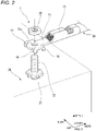
Fig. 2 is an exploded perspective view of the fixing structure shown inFig. 1 . -
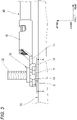
Fig. 3 is a side view of the fixing structure shown inFig. 1 . -
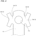
Fig. 4 is a front view of a part of the ground terminal according to the present embodiment as viewed from above. -
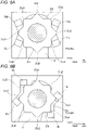
Fig. 5A is a cross-sectional view taken along a line A-A shown inFig. 3 , andFig. 5B is a view corresponding toFig. 5A fixed at an angle different from that ofFig. 5A . -
Fig. 6A is an enlarged view showing a mode in which a rotation stop portion is engaged with a seat,Fig. 6B is an enlarged view of an engaging portion inFig. 6A, and Fig. 6C and Fig. 6D are views according to modifications ofFig. 6A . - Hereinafter, a
ground terminal 10 and a fixing structure 1 of theground terminal 10 according to an embodiment of the present disclosure will be described with reference to the drawings. In the example shown inFig. 1 , the fixing structure 1 of theground terminal 10 shows a state in which ascrew portion 22 of abolt 20 is inserted into athrough hole 11a of theground terminal 10, aflat surface portion 11 and aseat 21 are in contact with each other, and arotation stop portion 14 sandwiches theseat 21 in a left-right direction to prevent rotation. - In the present embodiment, a terminal is referred to as the "
ground terminal 10", and a fixing member is referred to as a "body 30". At theground terminal 10, an end of anelectric wire 40 is crimped to acrimp portion 18 so as to be electrically connected to theelectric wire 40. - Hereinafter, for convenience of description, a "front-rear direction", an "upper-lower direction", the "left-right direction", a "front", a "rear", "upper", "lower", "left", and "right" are defined as shown in
Figs. 1 and2 . The "front-rear direction", the "upper-lower direction", and the "left-right direction" are orthogonal to one another. The left-right direction is left and right when the ground terminal is viewed from above (seeFig. 3 ). - In the fixing structure 1 according to the present embodiment, as shown in
Fig. 1 , anut 50 is used for thebolt 20 so as to protrude upward from thebody 30, and theground terminal 10 to which the end of theelectric wire 40 is crimped is fastened and fixed so as to be electrically connected to theelectric wire 40. At this time, theground terminal 10 and thebody 30 are electrically connected via thebolt 20. In the present embodiment, theground terminal 10 is fastened (fixed) to thebolt 20 by using thenut 50, but a different member may be used as long as theground terminal 10 is fixed. - First, the
ground terminal 10 will be described. Theground terminal 10 is formed of a conductive member. As shown inFigs. 1 to 3 , theground terminal 10 is fixed to thebody 30 from an upper side of thebody 30 via thebolt 20. - As shown in
Figs. 1 to 4 , theground terminal 10 includes theflat surface portion 11, a pair of extendingportions 12, a pair ofbranch portions 13, and therotation stop portion 14. Further, theground terminal 10 also includes thecrimp portion 18 on which the end of theelectric wire 40 is placed and the end of theelectric wire 40 is crimped. - As shown in
Figs. 1 to 4 , theflat surface portion 11 has a substantially rectangular flat plate shape whose rear end extends from thecrimp portion 18 along the front-rear direction and toward a front side. The throughhole 11a into which thescrew portion 22 of thebolt 20 is inserted is provided on a front end side of theflat surface portion 11. - In particular, as shown in
Fig. 4 , the pair of extendingportions 12 extend in the left-right direction from side faces of theflat surface portion 11 in the left-right direction. Specifically, an extendingportion 12a provided on a right side face of theflat surface portion 11 extends along the left-right direction and toward a right side, and an extendingportion 12b provided on a left side face of theflat surface portion 11 extends along the left-right direction and toward a left side. The pair of extendingportions 12 sandwich theflat surface portion 11 in the left-right direction. - In particular, as shown in
Fig. 4 , the pair ofbranch portions 13 extend in a direction different from the direction in which each extendingportion 12 extends. Specifically, abranch portion 13a on a side of the extendingportion 12a has a substantially V shape having a portion extending on the front side and the right side and a portion extending on a rear side and the right side, and abranch portion 13b on a side of the extendingportion 12b has a substantially V shape having a portion extending on the front side and the left side and a portion extending on the rear side and the left side. The pair ofbranch portions 13 sandwich theflat surface portion 11 and the extendingportion 12 in the left-right direction. - The
rotation stop portion 14 extends from each end portion of the pair ofbranch portions 13 toward a lower side along the upper-lower direction. In other words, therotation stop portion 14 has a shape in which thebranch portion 13 is bent toward the lower side. Thus, tworotation stop portions 14 are provided at each of thebranch portion 13a and thebranch portion 13b. - An end surface of the
rotation stop portion 14 is positioned on the lower side relative to a surface of thebolt 20 facing thebody 30. In other words, a length of therotation stop portion 14 in the upper-lower direction is longer than a length (that is, a thickness) of theseat 21 of thebolt 20 to be described later in the upper-lower direction (seeFig. 3 ). The length of therotation stop portion 14 in the upper-lower direction may be shorter than the length of theseat 21 in the upper-lower direction. - The
rotation stop portion 14 on the left side and the front side is referred to as a "rotation stopportion 14a", therotation stop portion 14 on the left side and the rear side is referred to as a "rotation stop portion 14b", therotation stop portion 14 on the right side and the rear side is referred to as a "rotation stop portion 14c", and therotation stop portion 14 on the right side and the front side is referred to as a "rotation stop portion 14d". - Next, the
bolt 20 will be described. Thebolt 20 is formed of a conductive member. As shown inFigs. 1 to 3 , thebolt 20 is formed integrally with thebody 30. Thebolt 20 includes theseat 21 that is in contact with theflat surface portion 11, and thescrew portion 22 that is inserted into the throughhole 11a. - In particular, as shown in
Figs. 5A and 5B , theseat 21 has a substantially star-shaped octagonal shape. That is, on an outer peripheral surface (that is, the outer peripheral surface in a circumferential direction) along the upper-lower direction of theseat 21, a convex portion 21a and aconcave portion 21b are continuously adjacent along the circumferential direction. The convex portion 21a is a portion protruding outward in the circumferential direction, and theconcave portion 21b is a portion recessed inward in the circumferential direction. The convex portion 21a includes convex portions 21a1 to 21a8. - As shown in
Fig. 3 , theseat 21 is separated from thebody 30. In other words, theseat 21 is provided so that a gap S is defined between theseat 21 and thebody 30. Since the gap S is defined between theseat 21 and thebody 30, the length of therotation stop portion 14 in the upper-lower direction can be made longer than the length of theseat 21 in the upper-lower direction. - Next, the fixing structure 1 of the
ground terminal 10 will be described.Fig. 5A is a view showing a state where therotation stop portion 14 and theseat 21 are engaged with each other in a mode shown inFigs. 1 to 3 .Fig. 5B is a view showing a state where therotation stop portion 14 is rotated to a left by 22.5° from the state shown inFig. 5A . - The
ground terminal 10 is positioned so that therotation stop portion 14 sandwiches theseat 21 at an intermediate stage of being fixed to thebody 30 via the bolt 20 (that is, during a fixing operation of the ground terminal) and at a fixing completion stage, and therotation stop portion 14 is engaged with theseat 21 as shown inFigs. 5A and 5B . - Specifically, the
ground terminal 10 is attached to thebolt 20 such that therotation stop portion 14a and therotation stop portion 14b, and therotation stop portion 14c and therotation stop portion 14d sandwich the convex portion 21a3 and the convex portion 21a7 (seeFig. 5A ). At this time, therotation stop portion 14a and therotation stop portion 14d, and therotation stop portion 14b and therotation stop portion 14c are positioned so as to sandwich twoconcave portions 21b adjacent to each other in the circumferential direction of theseat 21. - More specifically, the
rotation stop portion 14a and therotation stop portion 14d sandwich theseat 21 in the left-right direction. At this time, an end portion on a right side (a left side in a sheet ofFigs. 5A and 5B ) and a rear side of therotation stop portion 14a contacts a side face of the convex portion 21a2, and an end portion on a left side and a rear side of therotation stop portion 14d contacts a side face of the convex portion 21a8. Thus, by sandwiching theseat 21 by therotation stop portion 14a and therotation stop portion 14d, clockwise and counterclockwise rotation of theground terminal 10 with respect to theseat 21 is prevented. - Similarly, the
rotation stop portion 14b and therotation stop portion 14c sandwich theseat 21 in the left-right direction, an end portion on a right side and a front side of therotation stop portion 14b contacts a side face of the convex portion 21a4, and an end portion on a left side and a front side of therotation stop portion 14c contacts a side face of the convex portion 21a6. Thus, the clockwise and counterclockwise rotation of theground terminal 10 with respect to theseat 21 is prevented. - By sandwiching the
seat 21 by therotation stop portion 14a and therotation stop portion 14c, the counterclockwise rotation is prevented, but the clockwise rotation is not prevented. However, by sandwiching theseat 21 by therotation stop portion 14b and therotation stop portion 14d, the clockwise rotation is prevented. - The grounding
terminal 10 can be attached to thebolt 20 such that therotation stop portion 14a and therotation stop portion 14b sandwich oneconcave portion 21b, and therotation stop portion 14c and therotation stop portion 14d sandwich oneconcave portion 21b (seeFig. 5B ). At this time, therotation stop portion 14a and therotation stop portion 14d, and therotation stop portion 14b and therotation stop portion 14c are positioned so as to sandwich twoconvex portions 21b adjacent to each other in the circumferential direction of theseat 21. - Specifically, the
rotation stop portion 14a and therotation stop portion 14b sandwich theseat 21 in the front-rear direction. At this time, a rear side face of therotation stop portion 14a contacts a side face of the convex portion 21a3, and a front side face of therotation stop portion 14b contacts the side surface of the convex portion 21a4. Thus, by sandwiching theseat 21 by therotation stop portion 14a and therotation stop portion 14b, the clockwise and counterclockwise rotation of theground terminal 10 with respect to theseat 21 is prevented. - Similarly, the
rotation stop portion 14c and therotation stop portion 14d sandwich theseat 21 in the front-rear direction, and a front side face of therotation stop portion 14c contacts a side face of the convex portion 21a7, and a rear side face of therotation stop portion 14d contacts the side face of the convex portion 21a8. Thus, the clockwise and counterclockwise rotation of theground terminal 10 with respect to theseat 21 is prevented. - By sandwiching the
seat 21 by therotation stop portion 14a and therotation stop portion 14c, the clockwise rotation is prevented, but the counterclockwise rotation is not prevented. However, by sandwiching theseat 21 by therotation stop portion 14b and therotation stop portion 14d, the counterclockwise rotation is prevented. - In the fixing structure 1 shown in
Fig. 5A , the contact between therotation stop portion 14 and the convex portion 21a is so-called point contact, and in the fixing structure 1 shown inFig. 5B , the contact between therotation stop portion 14 and the convex portion 21a is so-called face contact. Whether the contact between therotation stop portion 14 and the convex portion 21a is the point contact or the face contact, there is no substantial difference in an effect of preventing the rotation of theground terminal 10. In the fixing structures 1 shown inFigs. 5A and 5B , therotation stop portion 14 and the convex portion 21a are in contact with each other, but a gap of a manufacturing tolerance is allowed. - In the
ground terminal 10 according to the present embodiment in which the rotation is prevented as described above, a mounting angle of theground terminal 10 with respect to thebolt 20 can be changed every 22.5°. Therefore, the mounting angle can be finely adjusted according to pulling and bending of theelectric wire 40. - According to the
ground terminal 10 of the present embodiment, theground terminal 10 includes theflat surface portion 11 that contacts theseat 21 of thebolt 20, the extendingportion 12 that extends on the same surface as a surface on which theflat surface portion 11 extends, thebranch portion 13 that extends on the same surface as the surface on which theflat surface portion 11 extends and extends in a direction different from the extending portion, and a plurality of rotation stopportions 14 that extend toward theseat 21 along a standing (or protruding) direction of thebolt 20. Theground terminal 10 according to the present embodiment is applied to thebolt 20 in which theseat 21 is separated from thebody 30, and is electrically connected to and fastened to thebody 30 by thebolt 20. Specifically, thescrew portion 22 of thebolt 20 is inserted into theflat surface portion 11 of theground terminal 10, and theflat surface portion 11 contacts theseat 21 to be electrically connected to thebody 30 via thebolt 20. Then, by positioning at least a pair of rotation stopportions 14 so as to sandwich theseat 21, the rotation of theground terminal 10 with respect to thebolt 20 is prevented. Thus, in theground terminal 10 according to the present embodiment, since the rotation of theground terminal 10 is prevented, a complexity of the fixing operation of theground terminal 10 with respect to thebody 30 is eliminated. In addition, since theground terminal 10 includes the extendingportion 12 and thebranch portion 13 extending on the same surface as theflat surface portion 11, a contact area with theseat 21 is increased, and thus conductivity with thebody 30 is improved as compared with a terminal in the related art. As a result, theground terminal 10 according to the present embodiment is excellent in workability while improving the conductivity with thebody 30. - Further, the end surface of the
rotation stop portion 14 is positioned on the lower side in the upper-lower direction relative to the surface on theseat 21 facing thebody 30, and compared with the terminal in the related art, the contact area (so-called engagement allowance) between therotation stop portion 14 and theseat 21 is secured. As a result, in theground terminal 10 according to the present embodiment, the rotation of theground terminal 10 with respect to thebolt 20 is prevented as compared with the terminal in the related art. - Further, since a temporary locking portion (
temporary locking protrusion 15a,inclined portion 15b, and a plurality ofsmall protrusions 15c), which is a part of therotation stop portion 14, can be engaged with theseat 21 of thebolt 20, displacement along the upper-lower direction is prevented. Specifically, even when the displacement in which theflat surface portion 11 is separated from theseat 21 along the upper-lower direction occurs in theground terminal 10, the temporary locking portion (temporary locking protrusion 15a,inclined portion 15b, and the plurality ofsmall protrusions 15c) interfere with theseat 21. As a result, in theground terminal 10 according to the present embodiment, not only the rotation but also the displacement along the upper-lower direction (so-called disconnection or detachment of the terminal) is prevented. - Since the
ground terminal 10 according to the present embodiment is applied to thebolt 20 in which theseat 21 is separated from the body 30 (that is, the gap S is defined by theseat 21 and the body 30), theground terminal 10 can be configured as described above. - According to the fixing structure 1 of the present embodiment, since the
ground terminal 10 as described above is applied to thebolt 20 in which the gap S is defined by theseat 21 and thebody 30, the workability is also excellent while the conductivity between theground terminal 10 and thebody 30 is being improved. - The present disclosure is not limited to the above embodiment, and modifications, improvements, and the like can be made as appropriate. In addition, a material, shape, size, number, arrangement position, and the like of each component in the above embodiment are optional and are not limited as long as the present disclosure can be achieved.
- For example, as shown in
Figs. 6A and 6B , thetemporary locking protrusion 15a may be provided on the side face of therotation stop portion 14. Thetemporary locking protrusion 15a is positioned in the gap S, and prevents the displacement of theground terminal 10 in the upper-lower direction. Specifically, when theground terminal 10 is moved with respect to thebolt 20 until theflat surface portion 11 contacts theseat 21, thetemporary locking protrusion 15a is positioned in the gap S. At this time, even if theground terminal 10 is displaced toward the upper side, thetemporary locking protrusion 15a contacts a lower surface of theseat 21, so that the displacement of theground terminal 10 in the upper-lower direction with respect to thebolt 20 is prevented. - As shown in
Fig. 6C , theinclined portion 15b may be provided instead of thetemporary locking protrusion 15a. Theinclined portion 15b preferably has a shape that approaches a central axis of the seat as an inclined surface moves downward. As shown inFig. 6D , the plurality ofsmall protrusions 15c may be provided instead of thetemporary locking protrusion 15a. As described above, by being formed so that a part of the rotation stop portion 14 (temporary locking protrusion 15a,inclined portion 15b, and the plurality ofsmall protrusions 15c) is positioned in the gap S, the displacement of theground terminal 10 in the upper-lower direction with respect to thebolt 20 is prevented. - As described above, a terminal such as the
ground terminal 10 is attachable to abolt 20, the bolt protruding from a fixing member such as thebody 30 and including aseat 21 separated from the fixing member, and the terminal is electrically connected to the fixing member when the terminal is attached to the bolt. The terminal includes: aflat surface portion 11; an extendingportion 12 continuous with the flat surface portion and extending to form a same surface as a surface of which the flat surface portion extends; abranch portion 13 continuous with the extending portion and extending to form a same surface as the surface of which the flat surface portion extends, thebranch portion 13 extending in a direction different from a direction in which the extending portion extends; and a plurality of rotation stopportions 14 continuous with the branch portion. When the terminal is attached to thebolt 20 by insertion of thebolt 20 into theflat surface portion 11, theflat surface portion 11 contacts theseat 21, the plurality of rotation stopportions 14 extend from thebranch portion 13 toward a base end of thebolt 20 in a protruding direction of thebolt 20, and at least a pair of the plurality of rotation stopportions 14 are positioned to sandwich theseat 21 in a direction intersecting the protruding direction to prevent rotation of the terminal such as theground terminal 10 with respect to thebolt 20. - According to the terminal, the terminal includes the flat surface portion that contacts the seat of the bolt, the extending portion extending to form the same surface as the surface of which the flat surface portion extends, the branch portion extending to form the same surface as the surface of which the flat surface portion extends and extending in the direction different from the direction in which the extending portion extends, and the plurality of rotation stop portions extending toward the base end in the protruding direction of the bolt. The terminal is attachable to the bolt including the seat separated from the fixing member, and is electrically connected to and fastened to the fixing member by the bolt. Specifically, when the bolt is inserted into the flat surface portion of the terminal, the flat surface portion contacts the seat to be electrically connected to the fixing member via the bolt. Then, by positioning at least a pair of rotation stop portions so as to sandwich the seat, the rotation of the terminal with respect to the bolt is prevented. Thus, in the terminal, since the rotation of the terminal is prevented, a complexity of the fixing operation of the terminal with respect to the fixing member is eliminated. In addition, since the terminal includes the extending portion and the branch portion extending to form the same surface as that of the flat surface portion, a contact area with the seat is increased, and thus conductivity with the fixing member is improved as compared with a terminal in the related art. As a result, the terminal is excellent in workability while improving the conductivity with the fixing member.
- In the terminal, end surfaces of the
rotation stop portion 14 are positioned closer to the base end than a surface of theseat 21 facing the fixing member. - According to the terminal, the end surface of the rotation stop portion is positioned closer to the base end in the protruding direction than the surface of the seat facing the fixing member, and compared with the terminal in the related art, the contact area (so-called engagement allowance) between the rotation stop portion and the seat is secured. As a result, in the terminal of the present configuration, the rotation of the terminal with respect to the bolt is prevented as compared with the terminal in the related art. Since the terminal is applicable to the bolt in which the seat is separated from the fixing member, the terminal can be configured as described above.
- In the terminal, at lease one of the rotation stop
portions 14 includes a temporary locking portion, such as thetemporary locking protrusion 15a, theinclined portion 15b, and the plurality ofsmall protrusions 15c, configured to be engaged with theseat 21. - According to the terminal, since the temporary locking portion, which is a part of the rotation stop portion, is configured to be engaged with the seat of the bolt, displacement along the standing direction is prevented. Specifically, even when the displacement in which the flat surface portion is separated from the seat along the standing direction occurs in the terminal, the temporary locking portion interferes with the seat. As a result, in the terminal of the present configuration, not only the rotation but also the displacement along the standing direction is prevented. Since the terminal of the present configuration is applied to the bolt in which the seat is separated from the fixing member, the terminal can be configured as described above.
- A terminal fixing structure such as the fixing structure 1 includes: a
bolt 20 protruding from a fixing member and including a seat separated from the fixing member; and the above-described terminal such as theground terminal 10. Thebolt 20 is inserted into theflat surface portion 11, and theflat surface portion 11 contacts theseat 12, and the rotation stopportions 14 of the terminal are positioned to sandwich theseat 21 to prevent rotation of the terminal with respect to thebolt 20. - According to the terminal fixing structure, the terminal is applied to the bolt including the seat separated from the fixing member. As a result, by an operation and effect of the terminal as described above, the fixing structure of the present configuration is also excellent in the workability while improving the conductivity between the terminal and the fixing member.
Claims (4)
- A terminal attachable to a bolt, the bolt protruding from a fixing member and comprising a seat separated from the fixing member, the terminal being electrically connected to the fixing member when the terminal is attached to the bolt, the terminal comprising:a flat surface portion;an extending portion continuous with the flat surface portion and extending to form a same surface as a surface of which the flat surface portion extends;a branch portion continuous with the extending portion and extending to form a same surface as the surface of which the flat surface portion extends, the branch portion extending in a direction different from a direction in which the extending portion extends; anda plurality of rotation stop portions continuous with the branch portion,wherein when the terminal is attached to the bolt by insertion of the bolt into the flat surface portion,the flat surface portion contacts the seat,the plurality of rotation stop portions extend from the branch portion toward a base end of the bolt in a protruding direction of the bolt, andat least a pair of the plurality of rotation stop portions are positioned to sandwich the seat in a direction intersecting the protruding direction to prevent rotation of the terminal with respect to the bolt.
- The terminal according to claim 1,
wherein end surfaces of the plurality of rotation stop portions are positioned closer to the base end than a surface of the seat facing the fixing member. - The terminal according to claim 1 or 2,
wherein at least one of the plurality of rotation stop portions comprises a temporary locking portion configured to be engaged with the seat. - A terminal fixing structure comprising:a bolt protruding from a fixing member and comprising a seat separated from the fixing member; andthe terminal according to any one of claims 1 to 3,wherein the bolt is inserted into the flat surface portion, and the flat surface portion contacts the seat, andwherein the plurality of rotation stop portions of the terminal are positioned to sandwich the seat to prevent rotation of the terminal with respect to the bolt.
Applications Claiming Priority (1)
| Application Number | Priority Date | Filing Date | Title |
|---|---|---|---|
| JP2020198704A JP7273019B2 (en) | 2020-11-30 | 2020-11-30 | Terminal and terminal fixing structure |
Publications (2)
| Publication Number | Publication Date |
|---|---|
| EP4007072A1 true EP4007072A1 (en) | 2022-06-01 |
| EP4007072B1 EP4007072B1 (en) | 2022-12-07 |
Family
ID=78827863
Family Applications (1)
| Application Number | Title | Priority Date | Filing Date |
|---|---|---|---|
| EP21209534.3A Active EP4007072B1 (en) | 2020-11-30 | 2021-11-22 | Assembly comprising a terminal and a bolt |
Country Status (4)
| Country | Link |
|---|---|
| US (1) | US11728580B2 (en) |
| EP (1) | EP4007072B1 (en) |
| JP (1) | JP7273019B2 (en) |
| CN (1) | CN114583483B (en) |
Citations (4)
| Publication number | Priority date | Publication date | Assignee | Title |
|---|---|---|---|---|
| EP1133007A1 (en) * | 2000-03-09 | 2001-09-12 | Sumitomo Wiring Systems, Ltd. | A construction and a terminal cap for preventing an erroneous connection |
| WO2004109863A2 (en) * | 2003-05-28 | 2004-12-16 | Valeo Equipements Electriques Moteur | Arrangement for securing a bond plug to a power outlet terminal secured to the rectifier device of a rotating electrical machine |
| FR3063393A1 (en) * | 2017-02-28 | 2018-08-31 | Peugeot Citroen Automobiles Sa | DEVICE FOR MOUNTING ELECTRIC TERMINALS. |
| JP2019160769A (en) | 2018-03-12 | 2019-09-19 | 矢崎総業株式会社 | Terminal attachment structure |
Family Cites Families (12)
| Publication number | Priority date | Publication date | Assignee | Title |
|---|---|---|---|---|
| US906476A (en) * | 1908-05-08 | 1908-12-08 | Albert Ullmann | Nut-lock. |
| US998514A (en) * | 1910-01-29 | 1911-07-18 | Benjamin Houghton | Nut-lock. |
| JPH0323664Y2 (en) * | 1986-05-01 | 1991-05-23 | ||
| JPH0447274U (en) * | 1990-08-28 | 1992-04-22 | ||
| JP2521697Y2 (en) * | 1991-09-30 | 1996-12-25 | 株式会社デンソー | Starter |
| JPH07192791A (en) * | 1993-12-28 | 1995-07-28 | Matsushita Electric Works Ltd | Cable connector terminal |
| US6250975B1 (en) * | 2000-11-30 | 2001-06-26 | Ewd., L.L.C. | Anti-rotation ground terminal for weld nut |
| US7056161B2 (en) * | 2001-02-20 | 2006-06-06 | Newfrey Llc | Grounding stud |
| US6855008B1 (en) * | 2003-10-06 | 2005-02-15 | Royal Die & Stamping Co., Inc. | Fuse holder with adjustable terminals |
| CN204927406U (en) * | 2015-08-25 | 2015-12-30 | 超威电源有限公司 | Locking lead acid battery terminal mounting structure that moves |
| JP2017142886A (en) * | 2016-02-08 | 2017-08-17 | 住友電装株式会社 | Grounding connection structure and grounding terminal fitting |
| CN206441880U (en) * | 2017-02-17 | 2017-08-25 | 深圳市土川投资管理有限公司 | A kind of connector, connection terminal and nut |
-
2020
- 2020-11-30 JP JP2020198704A patent/JP7273019B2/en active Active
-
2021
- 2021-11-22 EP EP21209534.3A patent/EP4007072B1/en active Active
- 2021-11-29 US US17/537,372 patent/US11728580B2/en active Active
- 2021-11-30 CN CN202111439376.9A patent/CN114583483B/en active Active
Patent Citations (4)
| Publication number | Priority date | Publication date | Assignee | Title |
|---|---|---|---|---|
| EP1133007A1 (en) * | 2000-03-09 | 2001-09-12 | Sumitomo Wiring Systems, Ltd. | A construction and a terminal cap for preventing an erroneous connection |
| WO2004109863A2 (en) * | 2003-05-28 | 2004-12-16 | Valeo Equipements Electriques Moteur | Arrangement for securing a bond plug to a power outlet terminal secured to the rectifier device of a rotating electrical machine |
| FR3063393A1 (en) * | 2017-02-28 | 2018-08-31 | Peugeot Citroen Automobiles Sa | DEVICE FOR MOUNTING ELECTRIC TERMINALS. |
| JP2019160769A (en) | 2018-03-12 | 2019-09-19 | 矢崎総業株式会社 | Terminal attachment structure |
Also Published As
| Publication number | Publication date |
|---|---|
| EP4007072B1 (en) | 2022-12-07 |
| US11728580B2 (en) | 2023-08-15 |
| CN114583483A (en) | 2022-06-03 |
| US20220173533A1 (en) | 2022-06-02 |
| JP7273019B2 (en) | 2023-05-12 |
| CN114583483B (en) | 2023-07-14 |
| JP2022086602A (en) | 2022-06-09 |
Similar Documents
| Publication | Publication Date | Title |
|---|---|---|
| JP3317174B2 (en) | Earth joint connector | |
| US10707603B2 (en) | Electrical cable connector | |
| US10770876B2 (en) | Electrical connection box and ground connection structure thereof | |
| US7364449B2 (en) | Joint connector block | |
| JPH06310200A (en) | Split multipolar connector | |
| US7442064B2 (en) | Board connecting body | |
| WO2015041329A1 (en) | Fuse unit attachment structure | |
| US9033727B2 (en) | Terminal platform block | |
| EP4007072A1 (en) | Terminal and terminal fixing structure | |
| JP2002260754A (en) | Terminal fitting for grounding | |
| US10615521B2 (en) | Coaxial cable connector provided with a housing having a pair of crimping pieces | |
| JP3944070B2 (en) | Earth joint connector | |
| US7059875B2 (en) | Ground metal fitting and ground structure for jacks of electronic devices | |
| US20200006885A1 (en) | Stacked connector and wire harness | |
| KR200477645Y1 (en) | A terminal for earthing | |
| US20200028294A1 (en) | Terminal | |
| JPH11301379A (en) | Ground wire connecting structure | |
| JP2582776Y2 (en) | Circuit insulation board | |
| US20230128481A1 (en) | Terminal unit | |
| JP2008235095A (en) | Joint connector for grounding, and wire connection structure | |
| JPH06310186A (en) | Short-circuiting structure for bus bar | |
| JP2987539B2 (en) | Bus bar connector | |
| CN100365877C (en) | Coaxial connector | |
| JP7393132B2 (en) | Board connector and board connector structure | |
| JP2002199556A (en) | Clamp for wire harness |
Legal Events
| Date | Code | Title | Description |
|---|---|---|---|
| PUAI | Public reference made under article 153(3) epc to a published international application that has entered the european phase |
Free format text: ORIGINAL CODE: 0009012 |
|
| STAA | Information on the status of an ep patent application or granted ep patent |
Free format text: STATUS: REQUEST FOR EXAMINATION WAS MADE |
|
| 17P | Request for examination filed |
Effective date: 20211122 |
|
| AK | Designated contracting states |
Kind code of ref document: A1 Designated state(s): AL AT BE BG CH CY CZ DE DK EE ES FI FR GB GR HR HU IE IS IT LI LT LU LV MC MK MT NL NO PL PT RO RS SE SI SK SM TR |
|
| GRAP | Despatch of communication of intention to grant a patent |
Free format text: ORIGINAL CODE: EPIDOSNIGR1 |
|
| STAA | Information on the status of an ep patent application or granted ep patent |
Free format text: STATUS: GRANT OF PATENT IS INTENDED |
|
| RIC1 | Information provided on ipc code assigned before grant |
Ipc: F16B 35/06 20060101ALI20220826BHEP Ipc: F16B 39/282 20060101ALI20220826BHEP Ipc: H01R 11/12 20060101ALI20220826BHEP Ipc: H01R 4/64 20060101ALI20220826BHEP Ipc: H01R 4/34 20060101ALI20220826BHEP Ipc: H01R 4/30 20060101AFI20220826BHEP |
|
| INTG | Intention to grant announced |
Effective date: 20220929 |
|
| GRAS | Grant fee paid |
Free format text: ORIGINAL CODE: EPIDOSNIGR3 |
|
| GRAA | (expected) grant |
Free format text: ORIGINAL CODE: 0009210 |
|
| STAA | Information on the status of an ep patent application or granted ep patent |
Free format text: STATUS: THE PATENT HAS BEEN GRANTED |
|
| AK | Designated contracting states |
Kind code of ref document: B1 Designated state(s): AL AT BE BG CH CY CZ DE DK EE ES FI FR GB GR HR HU IE IS IT LI LT LU LV MC MK MT NL NO PL PT RO RS SE SI SK SM TR |
|
| REG | Reference to a national code |
Ref country code: GB Ref legal event code: FG4D |
|
| REG | Reference to a national code |
Ref country code: CH Ref legal event code: EP Ref country code: AT Ref legal event code: REF Ref document number: 1536846 Country of ref document: AT Kind code of ref document: T Effective date: 20221215 |
|
| REG | Reference to a national code |
Ref country code: DE Ref legal event code: R096 Ref document number: 602021000921 Country of ref document: DE |
|
| REG | Reference to a national code |
Ref country code: IE Ref legal event code: FG4D |
|
| REG | Reference to a national code |
Ref country code: LT Ref legal event code: MG9D |
|
| REG | Reference to a national code |
Ref country code: NL Ref legal event code: MP Effective date: 20221207 |
|
| PG25 | Lapsed in a contracting state [announced via postgrant information from national office to epo] |
Ref country code: SE Free format text: LAPSE BECAUSE OF FAILURE TO SUBMIT A TRANSLATION OF THE DESCRIPTION OR TO PAY THE FEE WITHIN THE PRESCRIBED TIME-LIMIT Effective date: 20221207 Ref country code: NO Free format text: LAPSE BECAUSE OF FAILURE TO SUBMIT A TRANSLATION OF THE DESCRIPTION OR TO PAY THE FEE WITHIN THE PRESCRIBED TIME-LIMIT Effective date: 20230307 Ref country code: LT Free format text: LAPSE BECAUSE OF FAILURE TO SUBMIT A TRANSLATION OF THE DESCRIPTION OR TO PAY THE FEE WITHIN THE PRESCRIBED TIME-LIMIT Effective date: 20221207 Ref country code: FI Free format text: LAPSE BECAUSE OF FAILURE TO SUBMIT A TRANSLATION OF THE DESCRIPTION OR TO PAY THE FEE WITHIN THE PRESCRIBED TIME-LIMIT Effective date: 20221207 Ref country code: ES Free format text: LAPSE BECAUSE OF FAILURE TO SUBMIT A TRANSLATION OF THE DESCRIPTION OR TO PAY THE FEE WITHIN THE PRESCRIBED TIME-LIMIT Effective date: 20221207 |
|
| REG | Reference to a national code |
Ref country code: AT Ref legal event code: MK05 Ref document number: 1536846 Country of ref document: AT Kind code of ref document: T Effective date: 20221207 |
|
| PG25 | Lapsed in a contracting state [announced via postgrant information from national office to epo] |
Ref country code: RS Free format text: LAPSE BECAUSE OF FAILURE TO SUBMIT A TRANSLATION OF THE DESCRIPTION OR TO PAY THE FEE WITHIN THE PRESCRIBED TIME-LIMIT Effective date: 20221207 Ref country code: PL Free format text: LAPSE BECAUSE OF FAILURE TO SUBMIT A TRANSLATION OF THE DESCRIPTION OR TO PAY THE FEE WITHIN THE PRESCRIBED TIME-LIMIT Effective date: 20221207 Ref country code: LV Free format text: LAPSE BECAUSE OF FAILURE TO SUBMIT A TRANSLATION OF THE DESCRIPTION OR TO PAY THE FEE WITHIN THE PRESCRIBED TIME-LIMIT Effective date: 20221207 Ref country code: HR Free format text: LAPSE BECAUSE OF FAILURE TO SUBMIT A TRANSLATION OF THE DESCRIPTION OR TO PAY THE FEE WITHIN THE PRESCRIBED TIME-LIMIT Effective date: 20221207 Ref country code: GR Free format text: LAPSE BECAUSE OF FAILURE TO SUBMIT A TRANSLATION OF THE DESCRIPTION OR TO PAY THE FEE WITHIN THE PRESCRIBED TIME-LIMIT Effective date: 20230308 |
|
| PG25 | Lapsed in a contracting state [announced via postgrant information from national office to epo] |
Ref country code: NL Free format text: LAPSE BECAUSE OF FAILURE TO SUBMIT A TRANSLATION OF THE DESCRIPTION OR TO PAY THE FEE WITHIN THE PRESCRIBED TIME-LIMIT Effective date: 20221207 |
|
| PG25 | Lapsed in a contracting state [announced via postgrant information from national office to epo] |
Ref country code: SM Free format text: LAPSE BECAUSE OF FAILURE TO SUBMIT A TRANSLATION OF THE DESCRIPTION OR TO PAY THE FEE WITHIN THE PRESCRIBED TIME-LIMIT Effective date: 20221207 Ref country code: RO Free format text: LAPSE BECAUSE OF FAILURE TO SUBMIT A TRANSLATION OF THE DESCRIPTION OR TO PAY THE FEE WITHIN THE PRESCRIBED TIME-LIMIT Effective date: 20221207 Ref country code: PT Free format text: LAPSE BECAUSE OF FAILURE TO SUBMIT A TRANSLATION OF THE DESCRIPTION OR TO PAY THE FEE WITHIN THE PRESCRIBED TIME-LIMIT Effective date: 20230410 Ref country code: EE Free format text: LAPSE BECAUSE OF FAILURE TO SUBMIT A TRANSLATION OF THE DESCRIPTION OR TO PAY THE FEE WITHIN THE PRESCRIBED TIME-LIMIT Effective date: 20221207 Ref country code: CZ Free format text: LAPSE BECAUSE OF FAILURE TO SUBMIT A TRANSLATION OF THE DESCRIPTION OR TO PAY THE FEE WITHIN THE PRESCRIBED TIME-LIMIT Effective date: 20221207 Ref country code: AT Free format text: LAPSE BECAUSE OF FAILURE TO SUBMIT A TRANSLATION OF THE DESCRIPTION OR TO PAY THE FEE WITHIN THE PRESCRIBED TIME-LIMIT Effective date: 20221207 |
|
| PG25 | Lapsed in a contracting state [announced via postgrant information from national office to epo] |
Ref country code: SK Free format text: LAPSE BECAUSE OF FAILURE TO SUBMIT A TRANSLATION OF THE DESCRIPTION OR TO PAY THE FEE WITHIN THE PRESCRIBED TIME-LIMIT Effective date: 20221207 Ref country code: IS Free format text: LAPSE BECAUSE OF FAILURE TO SUBMIT A TRANSLATION OF THE DESCRIPTION OR TO PAY THE FEE WITHIN THE PRESCRIBED TIME-LIMIT Effective date: 20230407 Ref country code: AL Free format text: LAPSE BECAUSE OF FAILURE TO SUBMIT A TRANSLATION OF THE DESCRIPTION OR TO PAY THE FEE WITHIN THE PRESCRIBED TIME-LIMIT Effective date: 20221207 |
|
| REG | Reference to a national code |
Ref country code: DE Ref legal event code: R097 Ref document number: 602021000921 Country of ref document: DE |
|
| PLBE | No opposition filed within time limit |
Free format text: ORIGINAL CODE: 0009261 |
|
| STAA | Information on the status of an ep patent application or granted ep patent |
Free format text: STATUS: NO OPPOSITION FILED WITHIN TIME LIMIT |
|
| PG25 | Lapsed in a contracting state [announced via postgrant information from national office to epo] |
Ref country code: DK Free format text: LAPSE BECAUSE OF FAILURE TO SUBMIT A TRANSLATION OF THE DESCRIPTION OR TO PAY THE FEE WITHIN THE PRESCRIBED TIME-LIMIT Effective date: 20221207 |
|
| 26N | No opposition filed |
Effective date: 20230908 |
|
| PG25 | Lapsed in a contracting state [announced via postgrant information from national office to epo] |
Ref country code: SI Free format text: LAPSE BECAUSE OF FAILURE TO SUBMIT A TRANSLATION OF THE DESCRIPTION OR TO PAY THE FEE WITHIN THE PRESCRIBED TIME-LIMIT Effective date: 20221207 |
|
| PGFP | Annual fee paid to national office [announced via postgrant information from national office to epo] |
Ref country code: DE Payment date: 20230929 Year of fee payment: 3 |