EP4006945A1 - System mit mindestens einer mobilen eiheit - Google Patents
System mit mindestens einer mobilen eiheit Download PDFInfo
- Publication number
- EP4006945A1 EP4006945A1 EP21209653.1A EP21209653A EP4006945A1 EP 4006945 A1 EP4006945 A1 EP 4006945A1 EP 21209653 A EP21209653 A EP 21209653A EP 4006945 A1 EP4006945 A1 EP 4006945A1
- Authority
- EP
- European Patent Office
- Prior art keywords
- unit
- support
- fusible
- melting temperature
- temperature
- Prior art date
- Legal status (The legal status is an assumption and is not a legal conclusion. Google has not performed a legal analysis and makes no representation as to the accuracy of the status listed.)
- Granted
Links
Images



Classifications
-
- H—ELECTRICITY
- H01—ELECTRIC ELEMENTS
- H01H—ELECTRIC SWITCHES; RELAYS; SELECTORS; EMERGENCY PROTECTIVE DEVICES
- H01H85/00—Protective devices in which the current flows through a part of fusible material and this current is interrupted by displacement of the fusible material when this current becomes excessive
- H01H85/02—Details
- H01H85/36—Means for applying mechanical tension to fusible member
-
- H—ELECTRICITY
- H01—ELECTRIC ELEMENTS
- H01H—ELECTRIC SWITCHES; RELAYS; SELECTORS; EMERGENCY PROTECTIVE DEVICES
- H01H85/00—Protective devices in which the current flows through a part of fusible material and this current is interrupted by displacement of the fusible material when this current becomes excessive
- H01H85/02—Details
- H01H85/0241—Structural association of a fuse and another component or apparatus
- H01H2085/0275—Structural association with a printed circuit board
-
- Y—GENERAL TAGGING OF NEW TECHNOLOGICAL DEVELOPMENTS; GENERAL TAGGING OF CROSS-SECTIONAL TECHNOLOGIES SPANNING OVER SEVERAL SECTIONS OF THE IPC; TECHNICAL SUBJECTS COVERED BY FORMER USPC CROSS-REFERENCE ART COLLECTIONS [XRACs] AND DIGESTS
- Y02—TECHNOLOGIES OR APPLICATIONS FOR MITIGATION OR ADAPTATION AGAINST CLIMATE CHANGE
- Y02E—REDUCTION OF GREENHOUSE GAS [GHG] EMISSIONS, RELATED TO ENERGY GENERATION, TRANSMISSION OR DISTRIBUTION
- Y02E60/00—Enabling technologies; Technologies with a potential or indirect contribution to GHG emissions mitigation
- Y02E60/10—Energy storage using batteries
Definitions
- a multitude of devices are electrically powered by electrical power supply devices comprising electrical energy storage units, such as batteries, and in particular lithium-ion batteries.
- electrical energy storage units such as batteries, and in particular lithium-ion batteries.
- a storage unit can more particularly experience overheating, or even thermal runaway, during which the temperature of the unit rises abnormally. There is then a risk of propagating the operating fault in the electrical power supply device, for example from the storage unit to other units, or even to the rest of the device.
- An object of the present invention is therefore to provide a system, in particular for the power supply, but not only, improving the disconnection of a unit during an operating fault which results in a temperature rise beyond a threshold temperature.
- the system disconnects the unit, in the sense that it moves the unit away from its elements for securing to the support.
- This disconnection can be electrical and/or at least partially thermal.
- the at least one unit in the second position, is in a state of less thermal connection with the support, and the at least one unit is not connected electrically to the support.
- the main vectors of propagation of an operating fault in the device, or even in the apparatus comprising it are cut off.
- Another aspect relates to an apparatus comprising at least one system according to the first aspect.
- the system may be an electrical power supply system and the device incorporating it may include at least one component powered electrically by the system.
- the retention device is also configured to oppose the gravity of the unit in a position of the apparatus in which the unit is in the first position; for example, the unit can be steered with a non-zero vertical component when using the apparatus, and the retention device also serves to counter gravity in this configuration.
- the position of use corresponds to a rolling position.
- the equipped device in particular a vehicle, will advantageously present a situation of use in which the retention device opposes the weight of the unit.
- Another aspect of the invention relates to a method of disconnecting a unit in a system. Beyond a melting temperature of a fusible element, a blocking of movement operated hitherto by a retention device is released so as to allow movement of the unit from a first position thanks to the thrust of an elastically deformable device prestressed in the first position.
- the term mobile corresponds to a rotational movement or to a translational movement or else to a combination of movements, for example the combination of a rotation and a translation.
- the term “united” used to qualify the connection between two parts means that the two parts are linked/fixed with respect to each other, according to at least one degree of freedom. For example, if it is indicated that two parts are integral in translation along a Y direction, this means that the parts can be movable relative to each other, possibly according to several degrees of freedom, excluding freedom in translation along the Y direction. In other words, if a part is moved along the Y direction, the other part performs the same movement.
- melting temperature is meant a temperature level from which a material passes from the solid state to the liquid state. This temperature threshold is well defined for a given material, the pressure conditions being little variable and therefore impacting the temperature at the margin. In general, it will be possible to choose a material whose melting temperature corresponds to a safety threshold temperature from which a disconnection of the unit is required.
- an element “based” on a material A is understood to mean an element comprising this material A only or this material A and possibly other materials.
- the element comprises a material A and an envelope configured to contain the element A, the envelope being able to be formed of at least one material distinct from the material A.
- the device comprising the system of the invention can be configured to be electrically powered by a lithium-ion battery whose unit or units form the cells.
- the operating kinematics which follow is described on a non-limiting basis for a storage unit 1.
- the system comprises a support 2 configured to receive the storage unit 1. It further comprises a retention device 4 for the storage unit 1 to support 2 and an elastically deformable device which tends to push unit 1 relative to the support.
- This assembly is configured to physically disconnect, and advantageously electrically and/or at least partially thermally, the unit 1 from the support 2 during an operating fault. This operating fault may more particularly be overheating, or even thermal runaway.
- the system is therefore more particularly configured to disconnect the storage unit 1 according to its temperature.
- the unit of storage 1 and support 2 are in a first position relative to each other.
- the storage unit 1 is fixed and electrically connected to the support 2.
- the storage unit 1 can in particular be fixed to the support 2 according to all its degrees of freedom.
- the temperature of the storage unit 1 can rise above a threshold temperature from which it is desired to trigger a disconnection of the unit.
- the system comprises at least one fuse element associated according to the embodiments with the elements bearing the references 4, 43, 45, having a predefined melting temperature, and which can be thermally connected to the storage unit 1, by direct contact or via the environment between the fuse element and the storage unit.
- the temperature of the fuse element can in turn rise above its melting temperature which here corresponds to the threshold temperature triggering the movement of the unit from the first position towards a second position.
- the storage unit 1 is not electrically connected to the support 2 in the second position.
- the operation of the storage unit 1 can be interrupted in the event of overheating.
- the risk of propagation of the operating fault by short-circuit, or by ejection of gas from the faulty storage unit, is thus avoided. Since these gases are generally hot, loaded with molten or burning conductive materials and corrosive in nature, their propagation in the system is minimized.
- the system is secure.
- the storage unit 1 is electrically disconnected from the support 2 and is in a state of lesser thermal connection with the support 2.
- the risk that overheating of the storage unit in fault spreads to other storage units 1 or to other system elements is limited. Synergistically between these two characteristics, the main vectors of propagation of the malfunction are then cut. The security of the power supply system is further increased.
- the thrust force exerted by the elastically deformable device can be a support force or a traction force.
- the term “thrust” therefore means the capacity of the elastically deformable device to push the unit back from the support 2.
- the melting temperature is greater than or equal to a maximum normal operating temperature of the unit 1.
- This temperature is the threshold from which one is overheated.
- the threshold temperature may be greater than or equal to the overheating temperature, or even the thermal runaway temperature of the storage unit 1. More preferably still, the melting temperature is between the overheating temperature and the temperature of thermal runaway of the storage unit. Thus, the disconnection of the storage unit is performed before its thermal runaway.
- the melting temperature is below 120°C, preferably below 100°C.
- the melting temperature can for example be substantially between 60° C. and 120° C., this range of temperatures being particularly suited to the example in which the storage units are lithium-ion batteries.
- the melting temperature may for example be substantially equal to 80°C.
- the support 2 may comprise electrical connectors 21, 22 complementary to the connection elements 11, 12 of the unit.
- the connectors of support 2 can be connected in series and/or in parallel by a power bus (designated in English by “ busbar ”) of support 2.
- a power bus generally consists of a set of bars or of conductive tracks on a printed circuit, for example copper. Note that the connectors 21, 22 of the support 2 can be connected in series and/or in parallel by any type of power network.
- the unit 1 is in the form of an elongated element, for example cylindrical, and having a front face 13, a rear face 14 opposite the front face 13, and, between these two faces, a wall 17.
- the front face 13 is located opposite one face of a support 2 having, for the example, a base plate.
- a retention device 4 holds the unit 1 relative to the support 2.
- This device is here in the form of a wire 43 having at each of its ends an anchor 41, 42 ensuring its attachment relative to the support 2.
- the term "wire” means any elongated structure capable of being stretched around the unit, and includes the notions of cable or strap.
- the anchors can be arranged at the level of the base plate of the support 2; the illustration provided is purely schematic.
- the wire 43 is applied to the unit, and preferably at least at the level of the rear face 14.
- the retention device 4 can be equipped with one or more elastic portions 44, for example in the form of a helical spring or an elastomer, to ensure minor movement damping of the unit relative to the support 2 and to ensure retention despite the thermal expansions of the unit 1 relative to the support 2.
- the retention device 4 is configured to tend to press the unit towards the support 2.
- the force produced by the retention device 4 opposes a thrust force developed by an elastically deformable device.
- the latter is in fact configured to produce a force tending to push the unit relative to the support, and, in the present case, to tend to move the front face 13 of the unit away from the base plate of the support 2 which faces him.
- the elastically deformable device comprises an element 31.
- the latter can typically be in the form of a spring, for example of the helical type or of the coil spring type, an example of which is shown in figure 4 .
- the unit 1 is in a situation of equilibrium, in the first position, the thrust force of the element 31 and the retention force of the device 4 producing this equilibrium; they are preferably in the same direction (but in opposite directions) which can be directed along a longitudinal axis of the unit; possibly, these forces are located on this axis.
- the complementary elements 31, 32 which at least partially produces the elastically deformable device.
- the sight of the figure 1 reflects that it is the first complementary element 31 which is made in the form of a spring element capable of deforming and remaining under stress in the first position of the unit visible in this figure.
- the second complementary element 32 is here in the form of metal tabs.
- the unit 1 in the first position presented to the figure 1 , the unit 1 is in a static situation vis-à-vis the support 2 to which it is attached. Unit 1 is also electrically connected in this position. This situation can however be thwarted in the event of an excessive rise in temperature, in order to move the unit 1 towards a second position further away from the support 2.
- the retention device 4 comprises a fusible element which has a temperature of melting ensuring the collapse (preferably irreversible) of the mechanical strength of the retention device when the melting temperature is exceeded; the term "cross" means a temperature of the fuse element from and beyond this melting temperature from a lower temperature.
- the fuse element is the whole of the wire 43 which forms the fuse element.
- it is another part, more insulated, or several parts which form the fuse element.
- the fuse element can be arranged at the level of the and/or the other of the anchorages 41, 42 or even at any place along the length of the wire 43.
- wire 43 is an elongated structure. Whether all of the wire 43 or only one or more parts of the wire 43 form the fuse element, the latter is in fact elongated. In fact, the exceeding of the melting temperature at any point of the fuse element due to local heating allows the breaking of the wire 43 and carries the release of the unit 1. The elongated nature of the wire therefore allows a gain in thermal inertia and better efficiency with regard to the separation of unit 1 and support 2.
- the representation of the figure 1 presents a retention device with a single wire 43. It is understood that a plurality of such wires can be distributed around the unit to complete the retention. For example, at least one complementary wire 43 can be arranged similarly to the first, but angularly offset by 90°.
- the figure 2 provides another embodiment.
- the first complementary element 31 of the connection device performs both the function elastically deformable device and an electrical connection function, it being recalled that this combination of functions is not necessarily necessary in the invention.
- a guide 20 at least partially surrounds the wall 17 of the unit 1 so as to guide it, here in a direction of translation directed along its longitudinal axis.
- the guide 20 can be formed with an envelope of section similar to that of the unit 1, with a slightly larger dimension.
- the guide 20 can be a cylindrical envelope surrounding a unit 20 which is itself cylindrical.
- any form of guide 20 capable of guiding the unit in its direction of movement from the first position to the second position falls within the scope of the invention.
- the guide 20 is connected to the support 2 so as to form a single mechanical assembly.
- the guide 20 only allows freedom of movement for the unit 1, namely the translational movement passing from the first to the second position.
- the unit 20 is held in the guide 20, against the thrust of the elastically deformable element 31, by a retention device 4 here in the form of a one or more abutment elements interfering with the path of movement of the unit 1 from the first position.
- abutment element or elements 4 protrude towards the inside of the guide 20 and block the unit 1, by abutting on its rear face 14.
- the fuse elements are the abutment elements 4, for example studs organized at several places on the inner wall of the guide 20, or even a continuous bead. It is understood that the fusion of the elements 4 releases the translation capacity of the unit.
- the faulty unit 1 can be ejected from the guide 20 after the translation guidance.
- the storage unit 1 can remain attached to the support 2 during movement from the first to the second position.
- the second complementary element 32 is in the form of a spring contact so as to accommodate any small movements of the unit, for example due to vibrations or thermal expansion.
- the picture 3 presents another example in which, to minimize the number of parts, mobility is implemented on the scale of a module consisting of a plurality of accumulators; the latter can then be mounted in parallel or in series or in a matrix from an electrical point of view. They are mechanically united within the module thus forming a complex unit.
- the illustration does not provide detail of the arrangement between the accumulators, but it forms a module having, as previously, a first and a second connection elements 11, 12.
- the latter are preferably located on the front face of the module forming the unit.
- the first complementary element 31 and the second complementary element 32 are both organized in the form of elastically deformable elements so as to serve both as electrical connection means and as elastically deformable devices tending to push the unity.
- the support 2 comprises a peripheral guide ring of a portion of the length of the unit. It is in this housing that the connection elements 11, 12 are connected to the support.
- a retention device 4 in the form of one or more threads runs through a portion of the unit so as to provide retention opposite to the pushing force of the elements 31, 32.
- a retention thread forming at least in part, the fuse element can travel in zigzag over part of the periphery and the rear face of the unit 1 while being connected right through to the crown for inserting the unit 20 into the support.
- the unit 1 further comprises a casing 16 covering part of the rest of the unit by its rear face and associated with a spring portion integral with the support 2.
- the spring portion comprises one or more leaf springs 46 capable of covering a distal end of the casing 16 in the first position of the unit 1.
- the spring portion can also be constituted by a deformable ring in flexion in one piece, rather than by blades.
- the spring portion is configured to be deformed in the first position, in particular by applying a bending force to its outer periphery, so as to apply one end 461 of this portion to the casing 16.
- the bending deformation can be kept under stress by means of a fuse element 45 in the form of a ring encircling the spring portion; and, when the spring portion is formed of a plurality of blades 46, the fuse element 45 will tend to bring them together.
- the distal end 461 of blades 46 comprises a hooked part folded down towards the casing 16 of the unit.
- the casing 16 comprises an edge 161 at its distal end directed outwards and capable of abutting on the hook part of the blades 46.
- This retention by obstacle emerges from the figure 5 .
- the fuse element 45 is no longer in the solid state, the bending of the blades 46 is released and the border 161 can escape from the hooked part of the end 461. Being no longer retained, the unit is mobilized by the spring elements 31, 32, to move away from the first position.
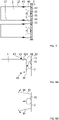
- the cross-sectional representation given at the Figure 6A shows a support 2 as before, with a first connector 21 capable of being placed in electrical continuity with the first connection element 11, a second connector 22 capable of being placed in electrical continuity with the second connection element 12, the elements 11, 12 here being the poles of an accumulator.
- the support further comprises a receiver 23 comprising an annular portion projecting above the face of the support 2 and capable of receiving, in partial insertion, the unit 1 by its front face 13.
- the unit is retained relative to the support 2 by means of a fusible element 45, for example in the form of a glue joint between the upper edge of the receiver 23 and the wall 17 of the unit 1.
- the thrust force is ensured here by the elastically deformable character of a first complementary element 31 and of a second complementary element 32 of the connection device ensuring the electrical continuity between the elements 11, 12, 21, 22.
- the first complementary element 31 is here central and in the form of a pressed contact, deformed in bending in the first position of the unit.
- the second complementary element 32 comprises a plurality of blades elastically deformed under pressure (however, it is not excluded that a single blade is sufficient, or at least two diametrically opposed blades), possibly folded as in the case of the Figure 6A , and connected on the one hand to the negative pole of the accumulator, and on the other hand to the connector 22 of the support 2.
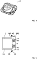
- FIG. 6B An example of realization in perspective is given at the figure 6B , with eight legs in the form of leaf springs for the elements 32.
- the plurality of legs having a spring function ensures a plurality of electrical contacts in parallel with a maintained contact pressure. This ensures a very low parasitic resistance making it possible to pass the current levels of the storages, in particular those at based on lithium-ion batteries.
- This example gives both central and peripheral balanced thrust on the front face of the unit.
- the fusible part forms a joint, advantageously continuous, between the wall of the unit and the receiver. The latter preferably formed integrally with the rest of the support 2.
- the part in the form of an annular ring of the receiver 23 can be integrated into the unit 20 and the fuse element 45 can be a bonding part between the edge of this annular ring and the face of the support 2.
- More blades 46 can be used, and they are, in this case, preferably evenly distributed around the unit.
- the blades 46 can be replaced by a single blade 46 in the form of a deformable crown in bending; or the blades 46 can be integral with a common crown-shaped base.
- a plurality of blades makes it possible to ensure a plurality of electrical contacts in parallel with a contact pressure maintained on each of these contacts. This ensures a very low parasitic resistance allowing the current levels of the lithium-ion accumulators to transit.
- the retention in the first position takes place by friction only, by pinching the unit thanks to the blades 46.
- the wall 17 of the unit 1 has a recess 15 which may be in the form of a groove.
- each blade 46 has a protrusion directed toward the unit and configured to fit into recess 15 in the first position of the unit.
- a retention by obstacle is achieved. If the melting temperature is reached, the blades 46 are released from unit 1 and deploy laterally; the unit is then no longer retained and the thrust exerted by the elastically deformable device generates a displacement.
- the elastically deformable device ensuring the thrust comprises the first complementary element 31 which is an electrical contact by pressure.
- Such grooves 15 exist on small cylindrical accumulators, for example of formats known under the numbers 18650 or 21700 of the International Electrotechnical Commission, that is to say 18 mm (respectively 21 mm) in diameter and 65 mm ( respectively 70 mm) long.
- the positive terminal 11 is fitted with an insulating peripheral seal ensuring the electrical insulation of the terminal 11 with respect to the case 17 and the sealing of the accumulator, and the terminal provided with its seal is crimped in the housing 17.
- the groove 15 is a result of this crimping operation, to provide support for the seal.
- the variant presented at the figure 8A and at the figure 8B differs little from the previous case.
- An obstacle cooperation is always formed there between blades 46 and a part of the outer surface of the unit 20, preferably at the level of the wall 17.
- the fuse element 45 is placed elsewhere, preferably at proximity to the distal end of the blades 46 to limit the movement of force necessary for fixing by the fusible part, located here far from the point of bending of the blade 46.
- Such a positioning ensures a constant controlled pressure on all points of electrical contact to minimize the overall equivalent parasitic resistance.
- the elasticity of the blades makes it possible to insert the unit 1 at the end of an assembly process.
- the fuse element 45 can be made in the form of a ring which, by default, maintains the blades 46 in the deformed position so as to delimit an insertion volume of the unit.
- This annular fuse element 45 can be received in a recess, preferably formed by crimping, on the blade or blades 46 making it possible to retain the ring on one side and forming an effective contact zone on the wall 17 of the unit of the other side.
- the support is for example made up of a printed circuit board and the blades can be simply welded (for example with a tin alloy) or fixed in a traversing manner on the latter. On insertion, each blade deforms slightly until the unit comes into the first position. Preferably, in this situation, the cooperation of a recess 15 of the unit with a projection 321 of the blade blocks any recoil.
- At least the last embodiment illustrated in figure 8A has the advantage that all the units are in the same direction and not mounted head to tail as is often the case in battery packs made from small cylindrical accumulators. Additionally, all vents evacuation of internal gases in the event of overpressure are located on the same side, which simplifies the design of the evacuation circuit for these gases outside the battery pack,
- figure 8B gives an example of the deployment of the blades releasing the unit.
- the fuse element has previously released the blades by its melting. This mechanism is similar to that of figure 5 and 7 .
- the material of the fuse element or elements it is possible to opt for an insulating material. Indeed, in an electrical application, the electrical connection in the first position is made at the level of the connection elements 11, 12 and not at the level of the fuse element(s).
- Using an insulating material has the advantage in this context of avoiding any problem linked to the differences in electrical potential between the elements in contact with the retention system. This also prevents that, as in the document DE 1 2101 038 066 A1 , the fuse elements constitute electrical connectors and that the latter are traversed by a current causing the local temperature to increase until it exceeds the melting temperature of the fuse elements, and this before the threshold temperature at the level of the unit 1 from from which its disconnection is required is reached.
- Insulating materials have the advantage of having a low melting temperature compared to the materials usually used in fuse systems.
- a melting temperature of the material of the fuse element(s) of between 60 and 120°C is chosen. These temperatures have the advantage of being compatible with the temperatures that can be tolerated by the various elements of the system and in particular unit 1.
- polyethylene it is possible in particular to use polyethylene.
- the solid-to-liquid transition temperature can be adjusted by the density and the implementation process of this material, for example between 70 and 80°C.
- Polyethylene has long molecules and the phase transition is not very marked in temperature. To have a smoother transition, smaller molecules can be used, for example to form a fusible adhesive.
- the figure 9 provides an example of the mechanical behavior of polyolefins, which are polymers of alkenes, as a function of temperature. Around 80°C, the Young's modulus of this material collapses, reflecting the phase transition.
- the maximum temperature in normal operation is typically of the order of 60° C., while the temperature of the first reaction leading to runaway of the battery is of the order of 100° C. C, so that the melting temperature of the material forming the fuse element is in this case well positioned between these two values.
- the invention proposes a system improving the disconnection of a unit during an operating fault, compared to existing solutions.
- a method of using such a system is also advantageous in a maintenance or recycling context. Indeed, in this case, it suffices to cut the fusible links, by a rise in temperature, to disassemble all units in a simple way. Fusion can take place either locally by bringing a source of heat to the required temperature, or by raising the temperature of the entire system or the entire device.
- the invention is not limited to the embodiments described above and extends to all the embodiments covered by the invention.
- the examples described illustrate in particular an absolute displacement of the storage unit 1 relative to the support 2, provision can be made for the support 2 to be movable between a first position and a second position in the system. For example, the support 2 slides in translation between the first position and the second position.
- the storage units shown in the drawings are cylindrical in shape. Provision can be made for the device 1 to be adapted to storage units of various formats and sizes.
Landscapes
- Fuses (AREA)
- Hooks, Suction Cups, And Attachment By Adhesive Means (AREA)
Applications Claiming Priority (1)
| Application Number | Priority Date | Filing Date | Title |
|---|---|---|---|
| FR2012138A FR3116664B1 (fr) | 2020-11-25 | 2020-11-25 | Système à au moins une unité mobile |
Publications (2)
| Publication Number | Publication Date |
|---|---|
| EP4006945A1 true EP4006945A1 (de) | 2022-06-01 |
| EP4006945B1 EP4006945B1 (de) | 2024-09-11 |
Family
ID=74553998
Family Applications (1)
| Application Number | Title | Priority Date | Filing Date |
|---|---|---|---|
| EP21209653.1A Active EP4006945B1 (de) | 2020-11-25 | 2021-11-22 | System mit mindestens einer mobilen einheit |
Country Status (2)
| Country | Link |
|---|---|
| EP (1) | EP4006945B1 (de) |
| FR (1) | FR3116664B1 (de) |
Citations (4)
| Publication number | Priority date | Publication date | Assignee | Title |
|---|---|---|---|---|
| EP1528586A1 (de) * | 2003-10-28 | 2005-05-04 | Nec Schott Components Corporation | Thermischer Sicherung mit thermischen Pellet und Verfahren zur Herstellung des Pellets |
| DE102010038066A1 (de) | 2010-08-06 | 2012-02-09 | Phoenix Contact Gmbh & Co. Kg | Thermische Überlastschutzanordnung |
| US20160020054A1 (en) * | 2014-07-16 | 2016-01-21 | Borgwarner Ludwigsburg Gmbh | Thermal fuse and printed circuit board with thermal fuse |
| WO2017121498A1 (en) * | 2016-01-14 | 2017-07-20 | Schurter Ag | Activatable thermal fuse |
-
2020
- 2020-11-25 FR FR2012138A patent/FR3116664B1/fr active Active
-
2021
- 2021-11-22 EP EP21209653.1A patent/EP4006945B1/de active Active
Patent Citations (4)
| Publication number | Priority date | Publication date | Assignee | Title |
|---|---|---|---|---|
| EP1528586A1 (de) * | 2003-10-28 | 2005-05-04 | Nec Schott Components Corporation | Thermischer Sicherung mit thermischen Pellet und Verfahren zur Herstellung des Pellets |
| DE102010038066A1 (de) | 2010-08-06 | 2012-02-09 | Phoenix Contact Gmbh & Co. Kg | Thermische Überlastschutzanordnung |
| US20160020054A1 (en) * | 2014-07-16 | 2016-01-21 | Borgwarner Ludwigsburg Gmbh | Thermal fuse and printed circuit board with thermal fuse |
| WO2017121498A1 (en) * | 2016-01-14 | 2017-07-20 | Schurter Ag | Activatable thermal fuse |
Also Published As
| Publication number | Publication date |
|---|---|
| EP4006945B1 (de) | 2024-09-11 |
| FR3116664A1 (fr) | 2022-05-27 |
| FR3116664B1 (fr) | 2023-08-25 |
Similar Documents
| Publication | Publication Date | Title |
|---|---|---|
| EP3624298B1 (de) | Batteriesatz aus akkus, das magnetische nebenschlüsse umfasst, die bei bedarf zum elektrischen schalten eines oder mehrerer dieser akkus betätigt werden können | |
| EP2375426B1 (de) | Varistor, der eine Elektrode mit einem vorstehenden Teil umfasst, der einen Kontakt bildet und Blitzableiter, der einen solchen Varistor umfasst | |
| EP2375424B1 (de) | Schutzvorrichtung gegen Überlastspannung mit parallelen Thermoabschaltern | |
| EP3624299B1 (de) | Batteriepaket aus elektrochemischen akkus, das vorrichtungen zur passiven magnetischen trennung zwischen den akkus und den sammelschienen umfasst, und gegebenenfalls einen passiven nebenschluss von einem oder mehreren akkus im falle eines ausfalls von einem von ihnen | |
| EP3044803B1 (de) | Schalter zum kurzschliessen einer gleichstrom-stromquelle | |
| FR2958789A1 (fr) | Dispositif de protection contre les surtensions transitoires a deconnecteur thermique ameliore | |
| EP4006941A1 (de) | Stromversorgungsvorrichtung mit einem wärmeempfindlichen stellglied und entsprechendes gerät | |
| EP3624232B1 (de) | Vorrichtung zum lichtbogenblasen mithilfe von druckgas bei einer verbindung/trennung zwischen einer ausgangsklemme eines elektrochemischen akkus und einer sammelschiene | |
| EP3624300B1 (de) | Verbindungs-/trennvorrichtung mit einem schnittstellenadapter zum befestigen um eine klemme eines elektrochemischen akkus herum, der mindestens einen magnetverschluss zur magnetischen befestigung mit elektrischer leitung der klemme zu einer sammelschiene umfasst | |
| FR3085793A1 (fr) | Procede d'assemblage d'un pack-batterie d'accumulateurs electrochimiques a des busbars par verrouillage magnetique | |
| EP4006945B1 (de) | System mit mindestens einer mobilen einheit | |
| EP4427252A1 (de) | System zum schutz gegen kurzschlüsse | |
| FR3085796A1 (fr) | Dispositif de connexion/deconnexion magnetique entre un accumulateur electrochimique et des busbars, et de shunt magnetique passif de l'accumulateur apres sa chute par gravite | |
| EP4006944B1 (de) | Unterbrechbares elektrisches verbindungssystem | |
| EP3624229B1 (de) | Ausgangsklemme eines elektrochemischen akkus, die einen magnetverschluss zur magnetischen befestigung mit elektrischer leitung mit einer sammelschiene umfasst | |
| EP4007027A1 (de) | Magnetisches verbindungssystem von mindestens einem elektrischen energiespeicher, speicher und zugehörige stromversorgung | |
| EP1815569B1 (de) | Überspannungsschutzeinrichtung mit verbesserter trennung | |
| EP3624230B1 (de) | Schnittstellenadapter, der mindestens einen magnetverschluss zur magnetischen befestigung mit elektrischer leitung von einem elektrochemischem akku zu einer sammelschiene umfasst | |
| EP3624158B1 (de) | Vorrichtung zur magnetischen lichtbogenlöschung bei einer verbindung/trennung zwischen einer ausgangsklemme eines elektrochemischen akkus und einer sammelschiene | |
| BE1030628B1 (fr) | Un dispositif de protection contre la coupure de courant pour véhicule électrique | |
| EP3559973B1 (de) | Selbstgetragene aktivierungsvorrichtung für einen elektromechanischen schalter | |
| FR3144415A1 (fr) | Connecteur de module accumulateur électrochimique, à portion frangible | |
| EP4007061A1 (de) | Fortgeschrittenes anschlusssystem von mindestens einem elektrischen energiespeicher, speicher und der zugehörigen stromversorgung | |
| FR2641649A1 (fr) | Dispositif de connexion entre troncons de cable plat |
Legal Events
| Date | Code | Title | Description |
|---|---|---|---|
| PUAI | Public reference made under article 153(3) epc to a published international application that has entered the european phase |
Free format text: ORIGINAL CODE: 0009012 |
|
| STAA | Information on the status of an ep patent application or granted ep patent |
Free format text: STATUS: REQUEST FOR EXAMINATION WAS MADE |
|
| 17P | Request for examination filed |
Effective date: 20211122 |
|
| AK | Designated contracting states |
Kind code of ref document: A1 Designated state(s): AL AT BE BG CH CY CZ DE DK EE ES FI FR GB GR HR HU IE IS IT LI LT LU LV MC MK MT NL NO PL PT RO RS SE SI SK SM TR |
|
| GRAP | Despatch of communication of intention to grant a patent |
Free format text: ORIGINAL CODE: EPIDOSNIGR1 |
|
| STAA | Information on the status of an ep patent application or granted ep patent |
Free format text: STATUS: GRANT OF PATENT IS INTENDED |
|
| RIC1 | Information provided on ipc code assigned before grant |
Ipc: H01H 85/02 20060101ALN20240326BHEP Ipc: H01H 85/36 20060101AFI20240326BHEP |
|
| INTG | Intention to grant announced |
Effective date: 20240416 |
|
| GRAS | Grant fee paid |
Free format text: ORIGINAL CODE: EPIDOSNIGR3 |
|
| GRAA | (expected) grant |
Free format text: ORIGINAL CODE: 0009210 |
|
| STAA | Information on the status of an ep patent application or granted ep patent |
Free format text: STATUS: THE PATENT HAS BEEN GRANTED |
|
| AK | Designated contracting states |
Kind code of ref document: B1 Designated state(s): AL AT BE BG CH CY CZ DE DK EE ES FI FR GB GR HR HU IE IS IT LI LT LU LV MC MK MT NL NO PL PT RO RS SE SI SK SM TR |
|
| REG | Reference to a national code |
Ref country code: GB Ref legal event code: FG4D Free format text: NOT ENGLISH |
|
| REG | Reference to a national code |
Ref country code: CH Ref legal event code: EP |
|
| REG | Reference to a national code |
Ref country code: DE Ref legal event code: R096 Ref document number: 602021018600 Country of ref document: DE |
|
| REG | Reference to a national code |
Ref country code: IE Ref legal event code: FG4D Free format text: LANGUAGE OF EP DOCUMENT: FRENCH |
|
| RAP4 | Party data changed (patent owner data changed or rights of a patent transferred) |
Owner name: COMMISSARIAT A L'ENERGIE ATOMIQUE ET AUX ENERGIESALTERNATIVES |
|
| REG | Reference to a national code |
Ref country code: LT Ref legal event code: MG9D |
|
| PG25 | Lapsed in a contracting state [announced via postgrant information from national office to epo] |
Ref country code: NO Free format text: LAPSE BECAUSE OF FAILURE TO SUBMIT A TRANSLATION OF THE DESCRIPTION OR TO PAY THE FEE WITHIN THE PRESCRIBED TIME-LIMIT Effective date: 20241211 |
|
| REG | Reference to a national code |
Ref country code: NL Ref legal event code: MP Effective date: 20240911 |
|
| PG25 | Lapsed in a contracting state [announced via postgrant information from national office to epo] |
Ref country code: GR Free format text: LAPSE BECAUSE OF FAILURE TO SUBMIT A TRANSLATION OF THE DESCRIPTION OR TO PAY THE FEE WITHIN THE PRESCRIBED TIME-LIMIT Effective date: 20241212 Ref country code: FI Free format text: LAPSE BECAUSE OF FAILURE TO SUBMIT A TRANSLATION OF THE DESCRIPTION OR TO PAY THE FEE WITHIN THE PRESCRIBED TIME-LIMIT Effective date: 20240911 |
|
| PG25 | Lapsed in a contracting state [announced via postgrant information from national office to epo] |
Ref country code: BG Free format text: LAPSE BECAUSE OF FAILURE TO SUBMIT A TRANSLATION OF THE DESCRIPTION OR TO PAY THE FEE WITHIN THE PRESCRIBED TIME-LIMIT Effective date: 20240911 |
|
| PG25 | Lapsed in a contracting state [announced via postgrant information from national office to epo] |
Ref country code: LV Free format text: LAPSE BECAUSE OF FAILURE TO SUBMIT A TRANSLATION OF THE DESCRIPTION OR TO PAY THE FEE WITHIN THE PRESCRIBED TIME-LIMIT Effective date: 20240911 |
|
| PG25 | Lapsed in a contracting state [announced via postgrant information from national office to epo] |
Ref country code: HR Free format text: LAPSE BECAUSE OF FAILURE TO SUBMIT A TRANSLATION OF THE DESCRIPTION OR TO PAY THE FEE WITHIN THE PRESCRIBED TIME-LIMIT Effective date: 20240911 |
|
| PG25 | Lapsed in a contracting state [announced via postgrant information from national office to epo] |
Ref country code: RS Free format text: LAPSE BECAUSE OF FAILURE TO SUBMIT A TRANSLATION OF THE DESCRIPTION OR TO PAY THE FEE WITHIN THE PRESCRIBED TIME-LIMIT Effective date: 20241211 Ref country code: ES Free format text: LAPSE BECAUSE OF FAILURE TO SUBMIT A TRANSLATION OF THE DESCRIPTION OR TO PAY THE FEE WITHIN THE PRESCRIBED TIME-LIMIT Effective date: 20240911 |
|
| PG25 | Lapsed in a contracting state [announced via postgrant information from national office to epo] |
Ref country code: RS Free format text: LAPSE BECAUSE OF FAILURE TO SUBMIT A TRANSLATION OF THE DESCRIPTION OR TO PAY THE FEE WITHIN THE PRESCRIBED TIME-LIMIT Effective date: 20241211 Ref country code: NO Free format text: LAPSE BECAUSE OF FAILURE TO SUBMIT A TRANSLATION OF THE DESCRIPTION OR TO PAY THE FEE WITHIN THE PRESCRIBED TIME-LIMIT Effective date: 20241211 Ref country code: LV Free format text: LAPSE BECAUSE OF FAILURE TO SUBMIT A TRANSLATION OF THE DESCRIPTION OR TO PAY THE FEE WITHIN THE PRESCRIBED TIME-LIMIT Effective date: 20240911 Ref country code: HR Free format text: LAPSE BECAUSE OF FAILURE TO SUBMIT A TRANSLATION OF THE DESCRIPTION OR TO PAY THE FEE WITHIN THE PRESCRIBED TIME-LIMIT Effective date: 20240911 Ref country code: GR Free format text: LAPSE BECAUSE OF FAILURE TO SUBMIT A TRANSLATION OF THE DESCRIPTION OR TO PAY THE FEE WITHIN THE PRESCRIBED TIME-LIMIT Effective date: 20241212 Ref country code: FI Free format text: LAPSE BECAUSE OF FAILURE TO SUBMIT A TRANSLATION OF THE DESCRIPTION OR TO PAY THE FEE WITHIN THE PRESCRIBED TIME-LIMIT Effective date: 20240911 Ref country code: ES Free format text: LAPSE BECAUSE OF FAILURE TO SUBMIT A TRANSLATION OF THE DESCRIPTION OR TO PAY THE FEE WITHIN THE PRESCRIBED TIME-LIMIT Effective date: 20240911 Ref country code: BG Free format text: LAPSE BECAUSE OF FAILURE TO SUBMIT A TRANSLATION OF THE DESCRIPTION OR TO PAY THE FEE WITHIN THE PRESCRIBED TIME-LIMIT Effective date: 20240911 |
|
| REG | Reference to a national code |
Ref country code: AT Ref legal event code: MK05 Ref document number: 1723469 Country of ref document: AT Kind code of ref document: T Effective date: 20240911 |
|
| PG25 | Lapsed in a contracting state [announced via postgrant information from national office to epo] |
Ref country code: NL Free format text: LAPSE BECAUSE OF FAILURE TO SUBMIT A TRANSLATION OF THE DESCRIPTION OR TO PAY THE FEE WITHIN THE PRESCRIBED TIME-LIMIT Effective date: 20240911 |
|
| PG25 | Lapsed in a contracting state [announced via postgrant information from national office to epo] |
Ref country code: PT Free format text: LAPSE BECAUSE OF FAILURE TO SUBMIT A TRANSLATION OF THE DESCRIPTION OR TO PAY THE FEE WITHIN THE PRESCRIBED TIME-LIMIT Effective date: 20250113 Ref country code: IS Free format text: LAPSE BECAUSE OF FAILURE TO SUBMIT A TRANSLATION OF THE DESCRIPTION OR TO PAY THE FEE WITHIN THE PRESCRIBED TIME-LIMIT Effective date: 20250111 |
|
| PG25 | Lapsed in a contracting state [announced via postgrant information from national office to epo] |
Ref country code: RO Free format text: LAPSE BECAUSE OF FAILURE TO SUBMIT A TRANSLATION OF THE DESCRIPTION OR TO PAY THE FEE WITHIN THE PRESCRIBED TIME-LIMIT Effective date: 20240911 Ref country code: SM Free format text: LAPSE BECAUSE OF FAILURE TO SUBMIT A TRANSLATION OF THE DESCRIPTION OR TO PAY THE FEE WITHIN THE PRESCRIBED TIME-LIMIT Effective date: 20240911 |
|
| PG25 | Lapsed in a contracting state [announced via postgrant information from national office to epo] |
Ref country code: EE Free format text: LAPSE BECAUSE OF FAILURE TO SUBMIT A TRANSLATION OF THE DESCRIPTION OR TO PAY THE FEE WITHIN THE PRESCRIBED TIME-LIMIT Effective date: 20240911 Ref country code: AT Free format text: LAPSE BECAUSE OF FAILURE TO SUBMIT A TRANSLATION OF THE DESCRIPTION OR TO PAY THE FEE WITHIN THE PRESCRIBED TIME-LIMIT Effective date: 20240911 |
|
| PG25 | Lapsed in a contracting state [announced via postgrant information from national office to epo] |
Ref country code: CZ Free format text: LAPSE BECAUSE OF FAILURE TO SUBMIT A TRANSLATION OF THE DESCRIPTION OR TO PAY THE FEE WITHIN THE PRESCRIBED TIME-LIMIT Effective date: 20240911 Ref country code: PL Free format text: LAPSE BECAUSE OF FAILURE TO SUBMIT A TRANSLATION OF THE DESCRIPTION OR TO PAY THE FEE WITHIN THE PRESCRIBED TIME-LIMIT Effective date: 20240911 |
|
| PG25 | Lapsed in a contracting state [announced via postgrant information from national office to epo] |
Ref country code: SK Free format text: LAPSE BECAUSE OF FAILURE TO SUBMIT A TRANSLATION OF THE DESCRIPTION OR TO PAY THE FEE WITHIN THE PRESCRIBED TIME-LIMIT Effective date: 20240911 Ref country code: IT Free format text: LAPSE BECAUSE OF FAILURE TO SUBMIT A TRANSLATION OF THE DESCRIPTION OR TO PAY THE FEE WITHIN THE PRESCRIBED TIME-LIMIT Effective date: 20240911 |
|
| REG | Reference to a national code |
Ref country code: DE Ref legal event code: R097 Ref document number: 602021018600 Country of ref document: DE |
|
| REG | Reference to a national code |
Ref country code: CH Ref legal event code: PL |
|
| PG25 | Lapsed in a contracting state [announced via postgrant information from national office to epo] |
Ref country code: MC Free format text: LAPSE BECAUSE OF FAILURE TO SUBMIT A TRANSLATION OF THE DESCRIPTION OR TO PAY THE FEE WITHIN THE PRESCRIBED TIME-LIMIT Effective date: 20240911 |
|
| PG25 | Lapsed in a contracting state [announced via postgrant information from national office to epo] |
Ref country code: DK Free format text: LAPSE BECAUSE OF FAILURE TO SUBMIT A TRANSLATION OF THE DESCRIPTION OR TO PAY THE FEE WITHIN THE PRESCRIBED TIME-LIMIT Effective date: 20240911 |
|
| PG25 | Lapsed in a contracting state [announced via postgrant information from national office to epo] |
Ref country code: LU Free format text: LAPSE BECAUSE OF NON-PAYMENT OF DUE FEES Effective date: 20241122 |
|
| REG | Reference to a national code |
Ref country code: CH Ref legal event code: PL |
|
| PLBE | No opposition filed within time limit |
Free format text: ORIGINAL CODE: 0009261 |
|
| STAA | Information on the status of an ep patent application or granted ep patent |
Free format text: STATUS: NO OPPOSITION FILED WITHIN TIME LIMIT |
|
| PG25 | Lapsed in a contracting state [announced via postgrant information from national office to epo] |
Ref country code: CH Free format text: LAPSE BECAUSE OF NON-PAYMENT OF DUE FEES Effective date: 20241130 |
|
| 26N | No opposition filed |
Effective date: 20250612 |
|
| REG | Reference to a national code |
Ref country code: BE Ref legal event code: MM Effective date: 20241130 |
|
| PG25 | Lapsed in a contracting state [announced via postgrant information from national office to epo] |
Ref country code: SE Free format text: LAPSE BECAUSE OF FAILURE TO SUBMIT A TRANSLATION OF THE DESCRIPTION OR TO PAY THE FEE WITHIN THE PRESCRIBED TIME-LIMIT Effective date: 20240911 |
|
| PG25 | Lapsed in a contracting state [announced via postgrant information from national office to epo] |
Ref country code: BE Free format text: LAPSE BECAUSE OF NON-PAYMENT OF DUE FEES Effective date: 20241130 |
|
| PG25 | Lapsed in a contracting state [announced via postgrant information from national office to epo] |
Ref country code: IE Free format text: LAPSE BECAUSE OF NON-PAYMENT OF DUE FEES Effective date: 20241122 |
|
| PGFP | Annual fee paid to national office [announced via postgrant information from national office to epo] |
Ref country code: DE Payment date: 20251118 Year of fee payment: 5 |
|
| PGFP | Annual fee paid to national office [announced via postgrant information from national office to epo] |
Ref country code: FR Payment date: 20251125 Year of fee payment: 5 |
|
| PG25 | Lapsed in a contracting state [announced via postgrant information from national office to epo] |
Ref country code: HU Free format text: LAPSE BECAUSE OF FAILURE TO SUBMIT A TRANSLATION OF THE DESCRIPTION OR TO PAY THE FEE WITHIN THE PRESCRIBED TIME-LIMIT; INVALID AB INITIO Effective date: 20211122 |
|
| PG25 | Lapsed in a contracting state [announced via postgrant information from national office to epo] |
Ref country code: CY Free format text: LAPSE BECAUSE OF FAILURE TO SUBMIT A TRANSLATION OF THE DESCRIPTION OR TO PAY THE FEE WITHIN THE PRESCRIBED TIME-LIMIT; INVALID AB INITIO Effective date: 20211122 |