EP4006666A1 - Article processing apparatus and downstream apparatus - Google Patents
Article processing apparatus and downstream apparatus Download PDFInfo
- Publication number
- EP4006666A1 EP4006666A1 EP21207020.5A EP21207020A EP4006666A1 EP 4006666 A1 EP4006666 A1 EP 4006666A1 EP 21207020 A EP21207020 A EP 21207020A EP 4006666 A1 EP4006666 A1 EP 4006666A1
- Authority
- EP
- European Patent Office
- Prior art keywords
- article
- downstream
- picture
- display
- processing apparatus
- Prior art date
- Legal status (The legal status is an assumption and is not a legal conclusion. Google has not performed a legal analysis and makes no representation as to the accuracy of the status listed.)
- Granted
Links
Images



Classifications
-
- G—PHYSICS
- G05—CONTROLLING; REGULATING
- G05B—CONTROL OR REGULATING SYSTEMS IN GENERAL; FUNCTIONAL ELEMENTS OF SUCH SYSTEMS; MONITORING OR TESTING ARRANGEMENTS FOR SUCH SYSTEMS OR ELEMENTS
- G05B19/00—Program-control systems
- G05B19/02—Program-control systems electric
- G05B19/18—Numerical control [NC], i.e. automatically operating machines, in particular machine tools, e.g. in a manufacturing environment, so as to execute positioning, movement or co-ordinated operations by means of program data in numerical form
- G05B19/402—Numerical control [NC], i.e. automatically operating machines, in particular machine tools, e.g. in a manufacturing environment, so as to execute positioning, movement or co-ordinated operations by means of program data in numerical form characterised by control arrangements for positioning, e.g. centring a tool relative to a hole in the workpiece, additional detection means to correct position
-
- B—PERFORMING OPERATIONS; TRANSPORTING
- B65—CONVEYING; PACKING; STORING; HANDLING THIN OR FILAMENTARY MATERIAL
- B65B—MACHINES, APPARATUS OR DEVICES FOR, OR METHODS OF, PACKAGING ARTICLES OR MATERIALS; UNPACKING
- B65B57/00—Automatic control, checking, warning, or safety devices
- B65B57/10—Automatic control, checking, warning, or safety devices responsive to absence, presence, abnormal feed, or misplacement of articles or materials to be packaged
- B65B57/14—Automatic control, checking, warning, or safety devices responsive to absence, presence, abnormal feed, or misplacement of articles or materials to be packaged and operating to control, or stop, the feed of articles or material to be packaged
-
- B—PERFORMING OPERATIONS; TRANSPORTING
- B65—CONVEYING; PACKING; STORING; HANDLING THIN OR FILAMENTARY MATERIAL
- B65B—MACHINES, APPARATUS OR DEVICES FOR, OR METHODS OF, PACKAGING ARTICLES OR MATERIALS; UNPACKING
- B65B1/00—Packaging fluent solid material, e.g. powders, granular or loose fibrous material, loose masses of small articles, in individual containers or receptacles, e.g. bags, sacks, boxes, cartons, cans, or jars
- B65B1/30—Devices or methods for controlling or determining the quantity or quality or the material fed or filled
- B65B1/32—Devices or methods for controlling or determining the quantity or quality or the material fed or filled by weighing
-
- B—PERFORMING OPERATIONS; TRANSPORTING
- B65—CONVEYING; PACKING; STORING; HANDLING THIN OR FILAMENTARY MATERIAL
- B65B—MACHINES, APPARATUS OR DEVICES FOR, OR METHODS OF, PACKAGING ARTICLES OR MATERIALS; UNPACKING
- B65B57/00—Automatic control, checking, warning, or safety devices
- B65B57/18—Automatic control, checking, warning, or safety devices causing operation of audible or visible alarm signals
-
- B—PERFORMING OPERATIONS; TRANSPORTING
- B65—CONVEYING; PACKING; STORING; HANDLING THIN OR FILAMENTARY MATERIAL
- B65B—MACHINES, APPARATUS OR DEVICES FOR, OR METHODS OF, PACKAGING ARTICLES OR MATERIALS; UNPACKING
- B65B65/00—Details peculiar to packaging machines and not otherwise provided for; Arrangements of such details
-
- B—PERFORMING OPERATIONS; TRANSPORTING
- B65—CONVEYING; PACKING; STORING; HANDLING THIN OR FILAMENTARY MATERIAL
- B65D—CONTAINERS FOR STORAGE OR TRANSPORT OF ARTICLES OR MATERIALS, e.g. BAGS, BARRELS, BOTTLES, BOXES, CANS, CARTONS, CRATES, DRUMS, JARS, TANKS, HOPPERS, FORWARDING CONTAINERS; ACCESSORIES, CLOSURES, OR FITTINGS THEREFOR; PACKAGING ELEMENTS; PACKAGES
- B65D88/00—Large containers
- B65D88/26—Hoppers, i.e. containers having funnel-shaped discharge sections
- B65D88/28—Construction or shape of discharge section
-
- G—PHYSICS
- G01—MEASURING; TESTING
- G01G—WEIGHING
- G01G19/00—Weighing apparatus or methods adapted for special purposes not provided for in the preceding groups
- G01G19/387—Weighing apparatus or methods adapted for special purposes not provided for in the preceding groups for combinatorial weighing, i.e. selecting a combination of articles whose total weight or number is closest to a desired value
- G01G19/393—Weighing apparatus or methods adapted for special purposes not provided for in the preceding groups for combinatorial weighing, i.e. selecting a combination of articles whose total weight or number is closest to a desired value using two or more weighing units
-
- G—PHYSICS
- G05—CONTROLLING; REGULATING
- G05B—CONTROL OR REGULATING SYSTEMS IN GENERAL; FUNCTIONAL ELEMENTS OF SUCH SYSTEMS; MONITORING OR TESTING ARRANGEMENTS FOR SUCH SYSTEMS OR ELEMENTS
- G05B19/00—Program-control systems
- G05B19/02—Program-control systems electric
- G05B19/418—Total factory control, i.e. centrally controlling a plurality of machines, e.g. direct or distributed numerical control [DNC], flexible manufacturing systems [FMS], integrated manufacturing systems [IMS] or computer integrated manufacturing [CIM]
- G05B19/41815—Total factory control, i.e. centrally controlling a plurality of machines, e.g. direct or distributed numerical control [DNC], flexible manufacturing systems [FMS], integrated manufacturing systems [IMS] or computer integrated manufacturing [CIM] characterised by the cooperation between machine tools, manipulators and conveyor or other workpiece supply system, workcell
-
- G—PHYSICS
- G05—CONTROLLING; REGULATING
- G05B—CONTROL OR REGULATING SYSTEMS IN GENERAL; FUNCTIONAL ELEMENTS OF SUCH SYSTEMS; MONITORING OR TESTING ARRANGEMENTS FOR SUCH SYSTEMS OR ELEMENTS
- G05B2219/00—Program-control systems
- G05B2219/30—Nc systems
- G05B2219/37—Measurements
- G05B2219/37565—Camera to detect precisely, crosshair, positions on workpiece by operator
-
- G—PHYSICS
- G05—CONTROLLING; REGULATING
- G05B—CONTROL OR REGULATING SYSTEMS IN GENERAL; FUNCTIONAL ELEMENTS OF SUCH SYSTEMS; MONITORING OR TESTING ARRANGEMENTS FOR SUCH SYSTEMS OR ELEMENTS
- G05B2219/00—Program-control systems
- G05B2219/30—Nc systems
- G05B2219/45—Nc applications
- G05B2219/45048—Packaging
-
- G—PHYSICS
- G05—CONTROLLING; REGULATING
- G05B—CONTROL OR REGULATING SYSTEMS IN GENERAL; FUNCTIONAL ELEMENTS OF SUCH SYSTEMS; MONITORING OR TESTING ARRANGEMENTS FOR SUCH SYSTEMS OR ELEMENTS
- G05B2219/00—Program-control systems
- G05B2219/30—Nc systems
- G05B2219/49—Nc machine tool, till multiple
- G05B2219/49113—Align elements like hole and drill, centering tool, probe, workpiece
-
- G—PHYSICS
- G05—CONTROLLING; REGULATING
- G05B—CONTROL OR REGULATING SYSTEMS IN GENERAL; FUNCTIONAL ELEMENTS OF SUCH SYSTEMS; MONITORING OR TESTING ARRANGEMENTS FOR SUCH SYSTEMS OR ELEMENTS
- G05B2219/00—Program-control systems
- G05B2219/30—Nc systems
- G05B2219/50—Machine tool, machine tool null till machine tool work handling
- G05B2219/50019—Zero, null offset
-
- G—PHYSICS
- G05—CONTROLLING; REGULATING
- G05B—CONTROL OR REGULATING SYSTEMS IN GENERAL; FUNCTIONAL ELEMENTS OF SUCH SYSTEMS; MONITORING OR TESTING ARRANGEMENTS FOR SUCH SYSTEMS OR ELEMENTS
- G05B2219/00—Program-control systems
- G05B2219/30—Nc systems
- G05B2219/50—Machine tool, machine tool null till machine tool work handling
- G05B2219/50036—Find center of circular mark, groove
-
- Y—GENERAL TAGGING OF NEW TECHNOLOGICAL DEVELOPMENTS; GENERAL TAGGING OF CROSS-SECTIONAL TECHNOLOGIES SPANNING OVER SEVERAL SECTIONS OF THE IPC; TECHNICAL SUBJECTS COVERED BY FORMER USPC CROSS-REFERENCE ART COLLECTIONS [XRACs] AND DIGESTS
- Y02—TECHNOLOGIES OR APPLICATIONS FOR MITIGATION OR ADAPTATION AGAINST CLIMATE CHANGE
- Y02P—CLIMATE CHANGE MITIGATION TECHNOLOGIES IN THE PRODUCTION OR PROCESSING OF GOODS
- Y02P90/00—Enabling technologies with a potential contribution to greenhouse gas [GHG] emissions mitigation
- Y02P90/02—Total factory control, e.g. smart factories, flexible manufacturing systems [FMS] or integrated manufacturing systems [IMS]
Definitions
- the present invention relates to an article processing apparatus and a downstream apparatus.
- the center of the article processing apparatus and the center of the downstream apparatus require aligning (for example, refer to JP 2009-258040 A ).
- center alignment is important for high-rate weighing and packaging.
- known has been the center alignment based on visual observation of a combination weighing apparatus and a packaging machine from all sides.
- center alignment based on a process including hanging a chain from the center of a combination weighing apparatus, attaching a jig to a stand supporting a former in a packaging machine, making a hole at the position of the jig corresponding to the center of the former, and adjusting the position of the packaging machine such that the chain hanging from the center of the combination weighing apparatus passes through the hole of the jig.
- an object of the present invention is to provide an article processing apparatus and a downstream apparatus that enable easy and accurate alignment of the center of the article processing apparatus and the center of the downstream apparatus.
- An article processing apparatus is summarized as an article processing apparatus that discharges an article to a downstream apparatus disposed downstream, the article processing apparatus including: a display; a capturing unit that captures a picture including at least part of the downstream apparatus; and a controller that displays, in a case where a processing operation of the article remains stopped in the article processing apparatus, on the display, the picture captured by the capturing unit.
- a downstream apparatus is summarized as a downstream apparatus that receives an article discharged from an article processing apparatus disposed upstream, the downstream apparatus processing the article, the downstream apparatus including: a display; a capturing unit that captures a picture including at least part of the article processing apparatus; and a controller that displays, in a case where a processing operation of the article remains stopped in the downstream apparatus, on the display, the picture captured by the capturing unit.
- FIGS. 1 and 2 An article processing apparatus (combination weighing apparatus) 1 and a downstream apparatus (packaging machine) 2 according to a first embodiment of the present invention will be described below with reference to FIGS. 1 and 2 .
- a combination weighing apparatus 1 is used as an article processing apparatus and a packaging machine 2 is used as a downstream apparatus.
- the present invention is not limited to the cases, and thus can be applied to a case where other apparatuses are used as an article processing apparatus and a downstream apparatus.
- given may be a case where a combination weighing apparatus is disposed as an article processing apparatus and a conveyance apparatus that conveys containers in sequence is used as a downstream apparatus.
- the combination weighing apparatus 1 discharges articles to the downstream apparatus 2 disposed downstream.
- the packaging machine 2 receives the articles discharged from the combination weighing apparatus 1 disposed upstream and then processes (packages) the articles.
- the combination weighing apparatus 1 includes a distribution feeder 3A, radial feeders 3B, pool hoppers 4, weighing hoppers 5, discharge chutes 6, a gathering chute 9, a mount 11, a controller 30, a main body 50, a capturing unit 100, and a display 110.
- the distribution feeder 3A is a smoothly conic member.
- a supply conveyer (not illustrated) provided outside, namely, above the distribution feeder 3A supplies articles to the distribution feeder 3A.
- the distribution feeder 3A has an upper face that vibrates due to an electromagnet, not illustrated, provided at the lower portion of the distribution feeder 3A.
- the distribution feeder 3A conveys the articles supplied on the upper face, radially in a circumferentially distributing manner, to supply each article to any of the radial feeders 3B.
- the radial feeders 3B are each a sheet-metal member made of a bent stainless-steel plate.
- the radial feeders 3B are disposed radially along the circumference of the distribution feeder 3A.
- the radial feeders 3B each have a conveyance face that vibrates due to an electromagnet (not illustrated) provided at the lower portion of the radial feeder 3B.
- the radial feeders 3B each convey the articles outward, due to vibration of the conveyance face.
- the pool hoppers 4 each temporarily accumulate the articles supplied from the corresponding radial feeder 3B, and then send the articles to the weighing hopper 5 disposed below the pool hopper 4.
- the weighing hoppers 5 each acquire the weight value of the temporarily accumulated articles sent from the corresponding pool hopper 4. Each acquired weight value is sent to the controller 30. The weighing hoppers 5 each discharge the articles to the discharge chute 6 disposed below the weighing hopper 5.
- the discharge chutes 6 each discharge, by sliding, the articles discharged from the corresponding weighing hopper 5, to the gathering chute 9.
- the gathering chute 9 slides down the articles discharged from each discharge chute 6, to the packaging machine 2.
- the main body 50 has an outer circumference along which drive units (not illustrated) that drive the respective corresponding hoppers (pool hoppers 4 and weighing hoppers 5) are attached. Each hopper is attached to the leading end of a hopper hanger (not illustrated) provided at the drive unit that drives the hopper.
- the combination weighing apparatus 1 is mounted on the mount 11.
- the packaging machine 2 is disposed in the housing space of the mount 11. In other words, the packaging machine 2 is disposed in the internal space surrounded by the mount 11.
- the capturing unit 100 captures a picture including at least part of the packaging machine 2.
- the capturing unit 100 is installed on the downstream side of the bottom 50A of the main body 50.
- the capturing unit 100 is achieved by a camera.
- the capturing unit 100 captures a picture from the upstream side to the downstream side in the conveyance direction MD of articles.
- the capturing unit 100 captures a picture from which a former 13 in the packaging machine 2 can be viewed through the outlet 9A of the gathering chute 9 or a downstream chute 12.
- the capturing unit 100 facing the downstream side from the bottom 50A captures an image every predetermined capturing cycle.
- the capturing unit 100 may record, as a still image or as a moving image, the image acquired every capturing cycle.
- the capturing unit 100 captures the picture described above in a first mode in which the processing operation of articles remains stopped in the combination weighing apparatus 1.
- the capturing unit 100 may capture the picture described above in a second mode in which the processing operation of articles is being performed in the combination weighing apparatus 1.
- the capturing unit 100 captures a picture from which the discharge state of articles discharged to the packaging machine 2 can be grasped through the outlet 9A of the gathering chute 9 or the downstream chute 12.
- the display 110 displays the picture captured by the capturing unit 100, in accordance with an instruction from the controller 30.
- the display 110 is provided outside the combination weighing apparatus 1, but may be provided at part of the combination weighing apparatus 1. Alternatively, the display 110 may be achieved by a display in an operation unit that operates the combination weighing apparatus 1.
- the controller 30 displays, on the display 110, the picture captured by the capturing unit 100.
- the controller 30 displays, on the display 110, the picture captured by the capturing unit 100 as a picture for adjustment of the positional relationship between the combination weighing apparatus 1 and the packaging machine 2.
- the controller 30 displays, on the display 110, the picture captured by the capturing unit 100. While verifying the picture displayed on the display 110, an operator aligns the center C1 of the combination weighing apparatus 1 and the center C2 of the former 13 in the packaging machine 2.
- the controller 30 displays, on the display 110, a guide G that facilitates adjustment of the positional relationship between the center C1 and the center C2 described above, together with the picture captured by the capturing unit 100.
- the guide G may include graduations each indicating the distance from its center O.
- the center O is identical to the center C1 described above.
- the controller 30 may display, on the display 110, a circle virtually indicating the outlet 9A of the gathering chute 9 or the outlet of the downstream chute 12, as a guide for attachment of the capturing unit 100.
- the operator can change the display style in pitch or the like of graduations by operating the display 110 (or operation unit). Specifically, the controller 30 changes the graduations displayed on the display 110 such that the pitch is set densely or coarsely.
- the controller 30 may further make a display such that part of the image captured by the capturing unit 100 is enlarged.
- the controller 30 can make a display such that the picture corresponding to the portion surrounded by the outlet 9A of the gathering chute 9 or the outlet of the downstream chute 12 is enlarged. This arrangement enables the operator to display a large picture for use in alignment, so that the work efficiency of the operator can be improved.
- the controller 30 may display the picture acquired by the capturing unit 100, directly, without such enlargement as above.
- the operator aligns the center C1 of the combination weighing apparatus 1 (outlet 9A of the gathering chute 9 or outlet of the downstream chute 12) and the center C2 of the packaging machine 2 (former 13) with the center O of the guide G, so that the center C1 of the combination weighing apparatus 1 and the center C2 of the packaging machine 2 are in alignment.
- the controller 30 may change the display aspect in outline of the outlet 9A of the gathering chute 9, as the guide G. For example, the controller 30 may display the outlet 9A of the gathering chute 9 or may delete the display of the outlet 9A of the gathering chute 9.
- the center position of a picture acquired by capturing with the capturing unit 100 depends on the accuracy of attachment of the capturing unit 100 to the main body 50. That is, in a case where the guide G is set uniformly to combination weighing apparatuses 1, the combination weighing apparatuses 1 are likely to differ in center C1 due to the individual differences of apparatuses. Furthermore, the position at which the capturing unit 100 is attached is likely to vary, for example, due to cleaning.
- the controller 30 has a function of calibrating display of the guide G to the display 110. Specifically, the controller 30 has a function of adjusting the position of display of the guide G to the image acquired by capturing with the capturing unit 100. In other words, the controller 30 has a function of changing the position of the guide G to be superimposed onto the picture that the display 110 displays.
- the controller 30 displays, on the display 110, the picture captured by the capturing unit 100 as a picture for verification of the discharge state of articles discharged to the packaging machine 2.
- the picture displayed by the display 110 may include a picture of the outlet 9A of the gathering chute 9 and a picture of the former 13 in the packaging machine 2, viewed from the upstream side to the downstream side in the conveyance direction MD of articles.
- controller 30 selects, from all combinations of the respective weight values acquired by the weighing hoppers 5, a combination within a predetermined allowable range and closest to the target value, and discharges the temporarily accumulated articles from the weighing hoppers 5 corresponding to the combination to the discharge chutes 6 disposed below the weighing hoppers 5.
- the packaging machine 2 includes the downstream chute 12, the former 13, and a conveyance unit 2A.
- the former 13 forms, into a tubular film, a sheet film sent from a film supply mechanism (not illustrated) in the packaging machine 2.
- the downstream chute 12 is provided downstream of the gathering chute 9, and the articles discharged from the gathering chute 9 are sent downstream through the inside of the downstream chute 12. Then, the articles are enclosed in the tubular film formed by the former 13.
- downstream chute 12 may detect metallic foreign matter in the articles discharged from the gathering chute 9.
- the conveyance unit 2A conveys the articles in a single package to a foreign-matter detection apparatus disposed downstream of the packaging machine 2.
- the operator in a case where the processing operation of articles remains stopped, the operator can verify, through the display (operation unit), a picture including at least part of the packaging machine 2, so that the combination weighing apparatus 1 and the packaging machine 2 can be installed properly.
- the operator can easily adjust the positional relationship between the combination weighing apparatus 1 and the packaging machine 2. That is, the center C1 of the combination weighing apparatus 1 and the center C2 of the packaging machine 2 can be easily aligned, so that an improvement can be made in work efficiency.
- the operator in a case where the processing operation of articles is being performed, on the basis of verification of the picture described above, the operator can verify the discharge state of articles from the combination weighing apparatus 1.
- the operator can verify the position of the packaging machine 2 through the outlet 9A of the gathering chute 9 included in the picture described above.
- the operator can align the center C1 of the combination weighing apparatus 1 and the center C2 of the packaging machine 2, more easily.
- the capturing unit 100 is installed on the downstream side of the bottom 50A of the main body 50, so that the picture described above can be captured without attachment and detachment of a jig or the like.
- any type of packaging machine or conveyance apparatus in conjunction with cups, trays, or buckets can be aligned with the combination weighing apparatus 1.
- the center C1 of the combination weighing apparatus 1 and the center C2 of the packaging machine 2 can be aligned.
- a capturing unit 200 is built in a main body 50.
- the capturing unit 200 captures a picture from the upstream side to the downstream side in the conveyance direction MD of articles, through a hole 50B provided at the bottom 50A of the main body 50.
- the capturing unit 200 is built in the main body 50, the capturing unit 200 can capture the picture described above without any influence due to the operation of the combination weighing apparatus 1.
- a capturing unit 300 is provided outside the side of a main body 50.
- the capturing unit 300 captures the picture described above, with a reflective plate 310 provided on the downstream side of the bottom 50A of the main body 50 and near the center C1.
- the capturing unit 300 is provided outside the side of the main body 50, the capturing unit 300 can capture the picture described above without any influence due to the operation of the combination weighing apparatus 1.
- the packaging machine 2 includes a capturing unit 400, a display 410, and a controller 420.
- the capturing unit 400 captures a picture including at least part of the combination weighing apparatus 1.
- the capturing unit 400 is provided near the center C2 of the packaging machine 2.
- the capturing unit 400 is achieved by a camera.
- the capturing unit 400 captures a picture from the downstream side to the upstream side in the conveyance direction MD of articles.
- the capturing unit 400 may capture a picture including an outlet 12A1 provided at the downstream end of a downstream chute 12.
- the display 410 displays the picture captured by the capturing unit 400, in accordance with an instruction from the controller 420.
- the display 410 is provided outside the packaging machine 2, but may be provided at part of the packaging machine 2.
- the display 410 may be achieved by a display in an operation unit that operates the packaging machine 2.
- the controller 420 may display, on the display 410, the picture captured by the capturing unit 400.
- the controller 420 may display, on the display 410, the picture captured by the capturing unit 400 as a picture for adjustment of the positional relationship between the combination weighing apparatus 1 and the packaging machine 2.
- the controller 420 may display, on the display 410, the picture captured by the capturing unit 400 as a picture for alignment of the center C1 of the combination weighing apparatus 1 and the center C2 of the packaging machine 2.
- the controller 420 may display, on the display 410, the picture captured by the capturing unit 400 as a picture for verification of the discharge state of articles discharged from the combination weighing apparatus 1.
- the picture displayed by the display 410 may include a picture of the outlet 9A of a gathering chute 9 and a picture of a former 13 in the packaging machine 2, viewed from the downstream side to the upstream side in the conveyance direction MD of articles.
- controller 420 may display a guide G on the display 410, similarly to a controller 30.
- an operator in a case where the processing operation of articles remains stopped, an operator can verify, through the display (operation unit), a picture including at least part of the combination weighing apparatus 1, so that the combination weighing apparatus 1 and the packaging machine 2 can be installed properly.
- Modification 3 in a case where the processing operation of articles is being performed, on the basis of verification of the picture described above, the operator can verify the discharge state of articles from the combination weighing apparatus 1.
Landscapes
- Engineering & Computer Science (AREA)
- Mechanical Engineering (AREA)
- Physics & Mathematics (AREA)
- General Physics & Mathematics (AREA)
- Quality & Reliability (AREA)
- Manufacturing & Machinery (AREA)
- Automation & Control Theory (AREA)
- General Engineering & Computer Science (AREA)
- Human Computer Interaction (AREA)
- Basic Packing Technique (AREA)
- Containers And Plastic Fillers For Packaging (AREA)
- Supply Of Fluid Materials To The Packaging Location (AREA)
Abstract
Description
- The present invention relates to an article processing apparatus and a downstream apparatus.
- In a case where an article processing apparatus, such a combination weighing apparatus, and a downstream apparatus, such as a packaging machine, are used in combination, in general, the center of the article processing apparatus and the center of the downstream apparatus require aligning (for example, refer to
JP 2009-258040 A - In particular, such center alignment is important for high-rate weighing and packaging.
- For example, known has been the center alignment based on visual observation of a combination weighing apparatus and a packaging machine from all sides.
- In addition, known has been the center alignment based on a process including hanging a chain from the center of a combination weighing apparatus, attaching a jig to a stand supporting a former in a packaging machine, making a hole at the position of the jig corresponding to the center of the former, and adjusting the position of the packaging machine such that the chain hanging from the center of the combination weighing apparatus passes through the hole of the jig.
- However, such conventional center alignment has a problem regarding accuracy or a problem in that its preparation is intricate.
- Thus, the present invention has been made in consideration of the problem, and an object of the present invention is to provide an article processing apparatus and a downstream apparatus that enable easy and accurate alignment of the center of the article processing apparatus and the center of the downstream apparatus.
- An article processing apparatus according to an embodiment is summarized as an article processing apparatus that discharges an article to a downstream apparatus disposed downstream, the article processing apparatus including: a display; a capturing unit that captures a picture including at least part of the downstream apparatus; and a controller that displays, in a case where a processing operation of the article remains stopped in the article processing apparatus, on the display, the picture captured by the capturing unit.
- A downstream apparatus according to an embodiment is summarized as a downstream apparatus that receives an article discharged from an article processing apparatus disposed upstream, the downstream apparatus processing the article, the downstream apparatus including: a display; a capturing unit that captures a picture including at least part of the article processing apparatus; and a controller that displays, in a case where a processing operation of the article remains stopped in the downstream apparatus, on the display, the picture captured by the capturing unit.
- According to the present invention, it is possible to provide an article processing apparatus and a downstream apparatus that enable easy and accurate alignment of the center of the article processing apparatus and the center of the downstream apparatus.
-
-
FIG. 1 is an explanatory view of an exemplary combination of an article processing apparatus (combination weighing apparatus) and a downstream apparatus (packaging machine) according to an embodiment; -
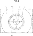
FIG. 2 is a view from upstream inFIG. 1 ; -
FIG. 3 is an explanatory view of an exemplary combination of an article processing apparatus (combination weighing apparatus) and a downstream apparatus (packaging machine) according toModification 1; -
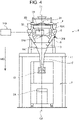
FIG. 4 is an explanatory view of an exemplary combination of an article processing apparatus (combination weighing apparatus) and a downstream apparatus (packaging machine) according toModification 2; and -
FIG. 5 is an explanatory view of an exemplary combination of an article processing apparatus (combination weighing apparatus) and a downstream apparatus (packaging machine) according to Modification 3. - Hereinafter, the present embodiment will be described in detail with reference to the attached drawings. In the following description of the drawings, the same or similar parts are denoted by the same or similar reference symbols. However, note that the drawings are schematic, and ratios of dimensions are different from actual ones. Therefore, specific dimensions and the like are determined in consideration of the following description. Moreover, there may be portions where dimensional relationships or proportions are different among the drawings. In this specification and the drawings, elements having substantially the same function and configuration are denoted by the same reference numerals to omit redundant description, and elements not directly related to the present invention are omitted.
- An article processing apparatus (combination weighing apparatus) 1 and a downstream apparatus (packaging machine) 2 according to a first embodiment of the present invention will be described below with reference to
FIGS. 1 and2 . In the present specification, given will be some cases where acombination weighing apparatus 1 is used as an article processing apparatus and apackaging machine 2 is used as a downstream apparatus. However, the present invention is not limited to the cases, and thus can be applied to a case where other apparatuses are used as an article processing apparatus and a downstream apparatus. For example, given may be a case where a combination weighing apparatus is disposed as an article processing apparatus and a conveyance apparatus that conveys containers in sequence is used as a downstream apparatus. - The
combination weighing apparatus 1 according to the present embodiment discharges articles to thedownstream apparatus 2 disposed downstream. Thepackaging machine 2 according to the present embodiment receives the articles discharged from thecombination weighing apparatus 1 disposed upstream and then processes (packages) the articles. - As illustrated in
FIG. 1 , thecombination weighing apparatus 1 according to the present embodiment includes adistribution feeder 3A,radial feeders 3B,pool hoppers 4, weighinghoppers 5,discharge chutes 6, agathering chute 9, amount 11, acontroller 30, amain body 50, a capturingunit 100, and adisplay 110. - The
distribution feeder 3A is a smoothly conic member. A supply conveyer (not illustrated) provided outside, namely, above thedistribution feeder 3A supplies articles to thedistribution feeder 3A. Thedistribution feeder 3A has an upper face that vibrates due to an electromagnet, not illustrated, provided at the lower portion of thedistribution feeder 3A. Thedistribution feeder 3A conveys the articles supplied on the upper face, radially in a circumferentially distributing manner, to supply each article to any of theradial feeders 3B. - The
radial feeders 3B are each a sheet-metal member made of a bent stainless-steel plate. Theradial feeders 3B are disposed radially along the circumference of thedistribution feeder 3A. - The
radial feeders 3B each have a conveyance face that vibrates due to an electromagnet (not illustrated) provided at the lower portion of theradial feeder 3B. Theradial feeders 3B each convey the articles outward, due to vibration of the conveyance face. - The
pool hoppers 4 each temporarily accumulate the articles supplied from the correspondingradial feeder 3B, and then send the articles to the weighinghopper 5 disposed below thepool hopper 4. - The weighing
hoppers 5 each acquire the weight value of the temporarily accumulated articles sent from thecorresponding pool hopper 4. Each acquired weight value is sent to thecontroller 30. The weighinghoppers 5 each discharge the articles to thedischarge chute 6 disposed below the weighinghopper 5. - The discharge chutes 6 each discharge, by sliding, the articles discharged from the corresponding weighing
hopper 5, to thegathering chute 9. - The
gathering chute 9 slides down the articles discharged from eachdischarge chute 6, to thepackaging machine 2. - The
main body 50 has an outer circumference along which drive units (not illustrated) that drive the respective corresponding hoppers (pool hoppers 4 and weighing hoppers 5) are attached. Each hopper is attached to the leading end of a hopper hanger (not illustrated) provided at the drive unit that drives the hopper. - As illustrated in
FIG. 1 , thecombination weighing apparatus 1 is mounted on themount 11. Note that, as illustrated inFIG. 1 , thepackaging machine 2 is disposed in the housing space of themount 11. In other words, thepackaging machine 2 is disposed in the internal space surrounded by themount 11. - The capturing
unit 100 captures a picture including at least part of thepackaging machine 2. In the present embodiment, as illustrated inFIG. 1 , the capturingunit 100 is installed on the downstream side of thebottom 50A of themain body 50. For example, the capturingunit 100 is achieved by a camera. - As illustrated in
FIG. 1 , the capturingunit 100 captures a picture from the upstream side to the downstream side in the conveyance direction MD of articles. For example, as illustrated inFIG. 2 , the capturingunit 100 captures a picture from which a former 13 in thepackaging machine 2 can be viewed through theoutlet 9A of thegathering chute 9 or adownstream chute 12. - The capturing
unit 100 facing the downstream side from thebottom 50A captures an image every predetermined capturing cycle. In this case, the capturingunit 100 may record, as a still image or as a moving image, the image acquired every capturing cycle. - Note that the capturing
unit 100 captures the picture described above in a first mode in which the processing operation of articles remains stopped in thecombination weighing apparatus 1. The capturingunit 100 may capture the picture described above in a second mode in which the processing operation of articles is being performed in thecombination weighing apparatus 1. - In the second mode, the capturing
unit 100 captures a picture from which the discharge state of articles discharged to thepackaging machine 2 can be grasped through theoutlet 9A of thegathering chute 9 or thedownstream chute 12. - The
display 110 displays the picture captured by the capturingunit 100, in accordance with an instruction from thecontroller 30. - In the present embodiment, as illustrated in
FIG. 1 , thedisplay 110 is provided outside thecombination weighing apparatus 1, but may be provided at part of thecombination weighing apparatus 1. Alternatively, thedisplay 110 may be achieved by a display in an operation unit that operates thecombination weighing apparatus 1. - In the first mode, the
controller 30 displays, on thedisplay 110, the picture captured by the capturingunit 100. - The
controller 30 displays, on thedisplay 110, the picture captured by the capturingunit 100 as a picture for adjustment of the positional relationship between thecombination weighing apparatus 1 and thepackaging machine 2. - Specifically, as illustrated in
FIG. 2 , thecontroller 30 displays, on thedisplay 110, the picture captured by the capturingunit 100. While verifying the picture displayed on thedisplay 110, an operator aligns the center C1 of thecombination weighing apparatus 1 and the center C2 of the former 13 in thepackaging machine 2. - In this case, as illustrated in
FIG. 2 , thecontroller 30 displays, on thedisplay 110, a guide G that facilitates adjustment of the positional relationship between the center C1 and the center C2 described above, together with the picture captured by the capturingunit 100. - As illustrated in
FIG. 2 , the guide G may include graduations each indicating the distance from its center O. In this case, the center O is identical to the center C1 described above. - In a case where the
capturing unit 100 captures a picture with the gatheringchute 9 removed, theoutlet 9A of the gatheringchute 9 is not displayed on thedisplay 110. Thus, thecontroller 30 may display, on thedisplay 110, a circle virtually indicating theoutlet 9A of the gatheringchute 9 or the outlet of thedownstream chute 12, as a guide for attachment of thecapturing unit 100. - The operator can change the display style in pitch or the like of graduations by operating the display 110 (or operation unit). Specifically, the
controller 30 changes the graduations displayed on thedisplay 110 such that the pitch is set densely or coarsely. - In the first mode, the
controller 30 may further make a display such that part of the image captured by the capturingunit 100 is enlarged. In this case, thecontroller 30 can make a display such that the picture corresponding to the portion surrounded by theoutlet 9A of the gatheringchute 9 or the outlet of thedownstream chute 12 is enlarged. This arrangement enables the operator to display a large picture for use in alignment, so that the work efficiency of the operator can be improved. - Meanwhile, in the second mode, for verification of the sliding state of articles in the
gathering chute 9, thecontroller 30 may display the picture acquired by the capturingunit 100, directly, without such enlargement as above. - The operator aligns the center C1 of the combination weighing apparatus 1 (
outlet 9A of the gatheringchute 9 or outlet of the downstream chute 12) and the center C2 of the packaging machine 2 (former 13) with the center O of the guide G, so that the center C1 of thecombination weighing apparatus 1 and the center C2 of thepackaging machine 2 are in alignment. - The
controller 30 may change the display aspect in outline of theoutlet 9A of the gatheringchute 9, as the guide G. For example, thecontroller 30 may display theoutlet 9A of the gatheringchute 9 or may delete the display of theoutlet 9A of the gatheringchute 9. - The center position of a picture acquired by capturing with the capturing
unit 100 depends on the accuracy of attachment of thecapturing unit 100 to themain body 50. That is, in a case where the guide G is set uniformly tocombination weighing apparatuses 1, thecombination weighing apparatuses 1 are likely to differ in center C1 due to the individual differences of apparatuses. Furthermore, the position at which thecapturing unit 100 is attached is likely to vary, for example, due to cleaning. - Thus, the
controller 30 has a function of calibrating display of the guide G to thedisplay 110. Specifically, thecontroller 30 has a function of adjusting the position of display of the guide G to the image acquired by capturing with the capturingunit 100. In other words, thecontroller 30 has a function of changing the position of the guide G to be superimposed onto the picture that thedisplay 110 displays. - In the second mode, the
controller 30 displays, on thedisplay 110, the picture captured by the capturingunit 100 as a picture for verification of the discharge state of articles discharged to thepackaging machine 2. - As illustrated in
FIGS. 1 and2 , the picture displayed by thedisplay 110 may include a picture of theoutlet 9A of the gatheringchute 9 and a picture of the former 13 in thepackaging machine 2, viewed from the upstream side to the downstream side in the conveyance direction MD of articles. - Note that the
controller 30 selects, from all combinations of the respective weight values acquired by the weighinghoppers 5, a combination within a predetermined allowable range and closest to the target value, and discharges the temporarily accumulated articles from the weighinghoppers 5 corresponding to the combination to thedischarge chutes 6 disposed below the weighinghoppers 5. - As illustrated in
FIG. 1 , thepackaging machine 2 according to the present embodiment includes thedownstream chute 12, the former 13, and aconveyance unit 2A. - The former 13 forms, into a tubular film, a sheet film sent from a film supply mechanism (not illustrated) in the
packaging machine 2. - Specifically, as illustrated in
FIG. 1 , thedownstream chute 12 is provided downstream of the gatheringchute 9, and the articles discharged from the gatheringchute 9 are sent downstream through the inside of thedownstream chute 12. Then, the articles are enclosed in the tubular film formed by the former 13. - Note that the
downstream chute 12 may detect metallic foreign matter in the articles discharged from the gatheringchute 9. - The
conveyance unit 2A conveys the articles in a single package to a foreign-matter detection apparatus disposed downstream of thepackaging machine 2. - According to the present embodiment, in a case where the processing operation of articles remains stopped, the operator can verify, through the display (operation unit), a picture including at least part of the
packaging machine 2, so that thecombination weighing apparatus 1 and thepackaging machine 2 can be installed properly. - According to the present embodiment, on the basis of verification of the picture described above, the operator can easily adjust the positional relationship between the
combination weighing apparatus 1 and thepackaging machine 2. That is, the center C1 of thecombination weighing apparatus 1 and the center C2 of thepackaging machine 2 can be easily aligned, so that an improvement can be made in work efficiency. - According to the present embodiment, in a case where the processing operation of articles is being performed, on the basis of verification of the picture described above, the operator can verify the discharge state of articles from the
combination weighing apparatus 1. - According to the present embodiment, the operator can verify the position of the
packaging machine 2 through theoutlet 9A of the gatheringchute 9 included in the picture described above. - Furthermore, according to the present embodiment, on the basis of the guide G described above, the operator can align the center C1 of the
combination weighing apparatus 1 and the center C2 of thepackaging machine 2, more easily. - According to the present embodiment, the capturing
unit 100 is installed on the downstream side of the bottom 50A of themain body 50, so that the picture described above can be captured without attachment and detachment of a jig or the like. - Note that, according to the present embodiment, any type of packaging machine or conveyance apparatus in conjunction with cups, trays, or buckets can be aligned with the
combination weighing apparatus 1. According to the present embodiment, even in a case where thecombination weighing apparatus 1 and thepackaging machine 2 differ in maker, the center C1 of thecombination weighing apparatus 1 and the center C2 of thepackaging machine 2 can be aligned. - With reference to
FIG. 3 , acombination weighing apparatus 1 and apackaging machine 2 according toModification 1 will be described below with a focus on the difference from thecombination weighing apparatus 1 and thepackaging machine 2 according to the embodiment described above. - In
Modification 1, as illustrated inFIG. 3 , acapturing unit 200 is built in amain body 50. InModification 1, the capturingunit 200 captures a picture from the upstream side to the downstream side in the conveyance direction MD of articles, through ahole 50B provided at the bottom 50A of themain body 50. - According to
Modification 1, because thecapturing unit 200 is built in themain body 50, the capturingunit 200 can capture the picture described above without any influence due to the operation of thecombination weighing apparatus 1. - With reference to
FIG. 4 , acombination weighing apparatus 1 and apackaging machine 2 according toModification 2 will be described below with a focus on the difference from thecombination weighing apparatus 1 and thepackaging machine 2 according to the embodiment described above. - In
Modification 2, as illustrated inFIG. 4 , acapturing unit 300 is provided outside the side of amain body 50. InModification 2, the capturingunit 300 captures the picture described above, with areflective plate 310 provided on the downstream side of the bottom 50A of themain body 50 and near the center C1. - According to
Modification 2, because thecapturing unit 300 is provided outside the side of themain body 50, the capturingunit 300 can capture the picture described above without any influence due to the operation of thecombination weighing apparatus 1. - With reference to
FIG. 5 , acombination weighing apparatus 1 and apackaging machine 2 according to Modification 3 will be described below with a focus on the difference from thecombination weighing apparatus 1 and thepackaging machine 2 according to the embodiment described above. - In Modification 3, as illustrated in
FIG. 5 , thepackaging machine 2 includes acapturing unit 400, adisplay 410, and acontroller 420. - The capturing
unit 400 captures a picture including at least part of thecombination weighing apparatus 1. In Modification 3, as illustrated inFIG. 5 , the capturingunit 400 is provided near the center C2 of thepackaging machine 2. For example, the capturingunit 400 is achieved by a camera. - As illustrated in
FIG. 5 , the capturingunit 400 captures a picture from the downstream side to the upstream side in the conveyance direction MD of articles. For example, the capturingunit 400 may capture a picture including an outlet 12A1 provided at the downstream end of adownstream chute 12. - The
display 410 displays the picture captured by the capturingunit 400, in accordance with an instruction from thecontroller 420. - In Modification 3, as illustrated in
FIG. 5 , thedisplay 410 is provided outside thepackaging machine 2, but may be provided at part of thepackaging machine 2. Thedisplay 410 may be achieved by a display in an operation unit that operates thepackaging machine 2. - In a case where the processing operation of articles remains stopped in the
packaging machine 2, thecontroller 420 may display, on thedisplay 410, the picture captured by the capturingunit 400. - The
controller 420 may display, on thedisplay 410, the picture captured by the capturingunit 400 as a picture for adjustment of the positional relationship between thecombination weighing apparatus 1 and thepackaging machine 2. - Specifically, as illustrated in
FIG. 5 , thecontroller 420 may display, on thedisplay 410, the picture captured by the capturingunit 400 as a picture for alignment of the center C1 of thecombination weighing apparatus 1 and the center C2 of thepackaging machine 2. - In a case where the processing operation of articles is being performed in the
packaging machine 2, thecontroller 420 may display, on thedisplay 410, the picture captured by the capturingunit 400 as a picture for verification of the discharge state of articles discharged from thecombination weighing apparatus 1. - The picture displayed by the
display 410 may include a picture of theoutlet 9A of agathering chute 9 and a picture of a former 13 in thepackaging machine 2, viewed from the downstream side to the upstream side in the conveyance direction MD of articles. - Furthermore, the
controller 420 may display a guide G on thedisplay 410, similarly to acontroller 30. - According to Modification 3, in a case where the processing operation of articles remains stopped, an operator can verify, through the display (operation unit), a picture including at least part of the
combination weighing apparatus 1, so that thecombination weighing apparatus 1 and thepackaging machine 2 can be installed properly. - According to Modification 3, in a case where the processing operation of articles is being performed, on the basis of verification of the picture described above, the operator can verify the discharge state of articles from the
combination weighing apparatus 1. - Although the present invention is explained in detail using the above-mentioned embodiments, it will be apparent to those skilled in the art that the present invention is not limited to the embodiments described herein. The present invention can be implemented as modifications and changes without departing from the spirit and scope of the present invention defined by the description of the claims. Accordingly, the description of the present specification is for the purpose of illustration and is not intended to limit the present invention in any way.
-
- 1
- article processing apparatus (combination weighing apparatus)
- 2
- downstream apparatus (packaging machine)
- 2A
- conveyance unit
- 3A
- distribution feeder
- 3B
- radial feeder
- 4
- pool hopper
- 5
- weighing hopper
- 6
- discharge chute
- 9
- gathering chute
- 9A
- outlet
- 11
- mount
- 12
- downstream chute
- 13
- former
- 30, 420
- controller
- 50
- main body
- 50A
- bottom
- 50B
- hole
- 100, 200, 300, 400
- capturing unit
- 110, 410
- display
- 310
- reflective plate
Claims (9)
- An article processing apparatus that discharges an article to a downstream apparatus disposed downstream, the article processing apparatus comprising:a display;a capturing unit that captures a picture including at least part of the downstream apparatus; anda controller that displays, in a case where a processing operation of the article remains stopped in the article processing apparatus, on the display, the picture captured by the capturing unit.
- The article processing apparatus according to claim 1, wherein
the controller displays, on the display, the picture captured by the capturing unit as a picture for adjustment of a positional relationship between the article processing apparatus and the downstream apparatus. - The article processing apparatus according to claim 1, wherein
the controller displays, in a case where the processing operation of the article is being performed in the article processing apparatus, on the display, the picture captured by the capturing unit as a picture for verification of a discharge state of the article discharged to the downstream apparatus. - The article processing apparatus according to any one of claims 1 to 3, further comprising:a hopper that temporarily accumulates the article input from outside; anda discharge chute that slides down the article discharged from the hopper, to the downstream apparatus, whereinthe picture includes a picture of an outlet of the discharge chute viewed from an upstream side to a downstream side in a conveyance direction of the article.
- The article processing apparatus according to claim 4, wherein
the controller displays, on the display, a guide for use in adjustment of a positional relationship between the outlet and a conveyance unit in the downstream apparatus, together with the picture. - The article processing apparatus according to claim 5, wherein
the controller changes a display aspect in outline of the outlet, as the guide. - The article processing apparatus according to any one of claims 4 to 6, further comprisinga main body having an outer circumference along which a drive unit that drives the hopper is attached, whereinthe capturing unit is installed on the downstream side of a bottom of the main body.
- The article processing apparatus according to any one of claims 4 to 6, further comprisinga main body having an outer circumference along which a drive unit that drives the hopper is attached, whereinthe capturing unit is built in the main body.
- A downstream apparatus that receives an article discharged from an article processing apparatus disposed upstream, the downstream apparatus processing the article, the downstream apparatus comprising:a display;a capturing unit that captures a picture including at least part of the article processing apparatus; anda controller that displays, in a case where a processing operation of the article remains stopped in the downstream apparatus, on the display, the picture captured by the capturing unit.
Applications Claiming Priority (1)
| Application Number | Priority Date | Filing Date | Title |
|---|---|---|---|
| JP2020197081A JP7587817B2 (en) | 2020-11-27 | 2020-11-27 | Article processing device and downstream device |
Publications (2)
| Publication Number | Publication Date |
|---|---|
| EP4006666A1 true EP4006666A1 (en) | 2022-06-01 |
| EP4006666B1 EP4006666B1 (en) | 2024-11-06 |
Family
ID=78592552
Family Applications (1)
| Application Number | Title | Priority Date | Filing Date |
|---|---|---|---|
| EP21207020.5A Active EP4006666B1 (en) | 2020-11-27 | 2021-11-08 | Article processing apparatus and downstream apparatus |
Country Status (5)
| Country | Link |
|---|---|
| US (1) | US12263979B2 (en) |
| EP (1) | EP4006666B1 (en) |
| JP (1) | JP7587817B2 (en) |
| CN (1) | CN114560146B (en) |
| DK (1) | DK4006666T3 (en) |
Citations (5)
| Publication number | Priority date | Publication date | Assignee | Title |
|---|---|---|---|---|
| JP2002059907A (en) * | 2000-08-18 | 2002-02-26 | Ishida Co Ltd | Packaging equipment |
| US20020161467A1 (en) * | 2000-05-12 | 2002-10-31 | Nobuki Hashiguchi | Production management system and system for checking operating conditions of product processing apparatuses |
| JP2009258040A (en) | 2008-04-21 | 2009-11-05 | Ishida Co Ltd | Combination weighing device |
| EP3098580A1 (en) * | 2014-01-20 | 2016-11-30 | Ishida Co., Ltd. | Combination weighing apparatus |
| EP3882184A1 (en) * | 2020-03-18 | 2021-09-22 | Ishida Co., Ltd. | Article conveyance apparatus |
Family Cites Families (26)
| Publication number | Priority date | Publication date | Assignee | Title |
|---|---|---|---|---|
| JP3138391B2 (en) * | 1993-08-05 | 2001-02-26 | 東京エレクトロン株式会社 | Alignment device and alignment method |
| JP2001325021A (en) * | 2000-05-12 | 2001-11-22 | Ishida Co Ltd | production management system |
| US7063256B2 (en) * | 2003-03-04 | 2006-06-20 | United Parcel Service Of America | Item tracking and processing systems and methods |
| DE10313492B4 (en) * | 2003-03-26 | 2005-06-23 | Maschinenfabrik Bernard Krone Gmbh | Apparatus and method for detecting and controlling the length of bales |
| US8888120B2 (en) * | 2007-01-25 | 2014-11-18 | Target Hitch Llc | Towing vehicle guidance for trailer hitch connection |
| ATE509568T1 (en) * | 2008-10-22 | 2011-06-15 | Sensomotoric Instr Ges Fuer Innovative Sensorik Mbh | METHOD AND DEVICE FOR IMAGE PROCESSING FOR COMPUTER-ASSISTED EYE OPERATIONS |
| US9250328B2 (en) * | 2009-09-30 | 2016-02-02 | Javad Gnss, Inc. | Graphics-aided remote position measurement with handheld geodesic device |
| EP2474810A1 (en) * | 2011-01-11 | 2012-07-11 | Leica Geosystems AG | Measuring device with a dynamic targeting functionality |
| EP2543960A1 (en) * | 2011-07-05 | 2013-01-09 | Hexagon Technology Center GmbH | Method for preparing target candidates for selecting a target |
| JP5817537B2 (en) * | 2012-01-11 | 2015-11-18 | 住友ベークライト株式会社 | Extruded product manufacturing method, extrusion mold manufacturing method, and image processing apparatus |
| JP5785123B2 (en) * | 2012-03-16 | 2015-09-24 | 株式会社イシダ | Combination weighing device |
| CN102700739B (en) * | 2012-06-20 | 2013-11-06 | 上海大和衡器有限公司 | Quantitative packaging scale for sub-package according to amount of grains and quantitative weighing method of quantitative packaging scale |
| CN103072207B (en) | 2013-01-31 | 2015-06-17 | 中联重科股份有限公司 | Feed position adjustment control method, device, system of mixer truck and mixer truck |
| WO2014129526A1 (en) * | 2013-02-20 | 2014-08-28 | 株式会社湯山製作所 | Medicine inspection device and system for individually packaging medicine |
| CN206330663U (en) | 2014-01-20 | 2017-07-14 | 株式会社石田 | Combined metering device |
| EP3101398B1 (en) * | 2014-01-30 | 2020-10-14 | Ishida Co., Ltd. | Combination weighing apparatus |
| JP6223849B2 (en) * | 2014-02-07 | 2017-11-01 | 大和製衡株式会社 | Combination scale |
| US9857144B2 (en) * | 2014-12-10 | 2018-01-02 | Flir Systems, Inc. | Electronic adaptive reticle systems and methods |
| US20160381297A1 (en) * | 2015-06-26 | 2016-12-29 | Jsc Yukon Advanced Optics Worldwide | Providing enhanced situational-awareness using magnified picture-in-picture within a wide field-of-view optical image |
| US10330292B2 (en) * | 2015-07-08 | 2019-06-25 | Production Resource Group Llc | Device for controlling a remotely located luminaire |
| CN205313056U (en) * | 2016-01-13 | 2016-06-15 | 淄博鲁凯树脂有限公司 | Full -automatic filling system |
| CN206691489U (en) * | 2017-05-19 | 2017-12-01 | 福建拓天生物科技有限公司 | A kind of packing machine for powder |
| CN207209441U (en) | 2017-07-31 | 2018-04-10 | 重庆拉瑞永固混凝土有限公司 | A kind of concrete mixing plant discharge port monitoring system |
| DE102017124895B3 (en) * | 2017-10-24 | 2019-03-28 | CLK GmbH | Foreign body detection in a multihead weigher |
| EP3933354B1 (en) * | 2020-06-30 | 2022-10-19 | Multipond Wägetechnik GmbH | Improved monitoring of combination scales using a 3d sensor |
| JP7597357B2 (en) * | 2020-11-12 | 2024-12-10 | 株式会社イシダ | Combination Weighing Device |
-
2020
- 2020-11-27 JP JP2020197081A patent/JP7587817B2/en active Active
-
2021
- 2021-11-08 DK DK21207020.5T patent/DK4006666T3/en active
- 2021-11-08 EP EP21207020.5A patent/EP4006666B1/en active Active
- 2021-11-15 US US17/454,972 patent/US12263979B2/en active Active
- 2021-11-22 CN CN202111385012.7A patent/CN114560146B/en active Active
Patent Citations (5)
| Publication number | Priority date | Publication date | Assignee | Title |
|---|---|---|---|---|
| US20020161467A1 (en) * | 2000-05-12 | 2002-10-31 | Nobuki Hashiguchi | Production management system and system for checking operating conditions of product processing apparatuses |
| JP2002059907A (en) * | 2000-08-18 | 2002-02-26 | Ishida Co Ltd | Packaging equipment |
| JP2009258040A (en) | 2008-04-21 | 2009-11-05 | Ishida Co Ltd | Combination weighing device |
| EP3098580A1 (en) * | 2014-01-20 | 2016-11-30 | Ishida Co., Ltd. | Combination weighing apparatus |
| EP3882184A1 (en) * | 2020-03-18 | 2021-09-22 | Ishida Co., Ltd. | Article conveyance apparatus |
Also Published As
| Publication number | Publication date |
|---|---|
| JP2022085409A (en) | 2022-06-08 |
| US12263979B2 (en) | 2025-04-01 |
| DK4006666T3 (en) | 2024-11-25 |
| EP4006666B1 (en) | 2024-11-06 |
| CN114560146A (en) | 2022-05-31 |
| JP7587817B2 (en) | 2024-11-21 |
| US20220169410A1 (en) | 2022-06-02 |
| CN114560146B (en) | 2024-10-01 |
Similar Documents
| Publication | Publication Date | Title |
|---|---|---|
| EP3258227B1 (en) | Conveyor apparatus and combined weighing apparatus | |
| US20100139222A1 (en) | Product filling system | |
| CN102806208B (en) | Granulous object sorting device | |
| JP2009105363A (en) | Bulk segment feeder, component supply attachment, electronic component processing device, and component transport device | |
| KR100477144B1 (en) | Weight sorter | |
| JP5308851B2 (en) | Combination weigher and weighing system | |
| JP2017047976A (en) | Method of controlling belt conveyer system | |
| EP4006666B1 (en) | Article processing apparatus and downstream apparatus | |
| JP6484052B2 (en) | Combination weighing device | |
| JP4199898B2 (en) | Agricultural product supply equipment | |
| CN213057798U (en) | Visual detection equipment for counter | |
| CN209061645U (en) | Moulding vision-based detection sorting machine | |
| JPH01297184A (en) | Weighing, sorting and feeding method and apparatus | |
| CN206330663U (en) | Combined metering device | |
| CN210449919U (en) | Automatic shot sorting system | |
| CN109242851A (en) | A kind of homogeneous material method of counting and device based on machine vision | |
| EP4411329A1 (en) | Weighing and counting apparatus | |
| EP4682484A1 (en) | Weighing apparatus | |
| CN114764021B (en) | Combined metering device | |
| JP7146626B2 (en) | Weighing device | |
| CN207497572U (en) | Screening plant | |
| KR100249844B1 (en) | Ic leadframe automatic inspection system and operating method | |
| CN111517066B (en) | Production line system | |
| JP7796223B2 (en) | Weight measurement weighing unit | |
| CN222520953U (en) | Feed divider and chamfer system of processing |
Legal Events
| Date | Code | Title | Description |
|---|---|---|---|
| PUAI | Public reference made under article 153(3) epc to a published international application that has entered the european phase |
Free format text: ORIGINAL CODE: 0009012 |
|
| STAA | Information on the status of an ep patent application or granted ep patent |
Free format text: STATUS: REQUEST FOR EXAMINATION WAS MADE |
|
| 17P | Request for examination filed |
Effective date: 20211108 |
|
| AK | Designated contracting states |
Kind code of ref document: A1 Designated state(s): AL AT BE BG CH CY CZ DE DK EE ES FI FR GB GR HR HU IE IS IT LI LT LU LV MC MK MT NL NO PL PT RO RS SE SI SK SM TR |
|
| GRAP | Despatch of communication of intention to grant a patent |
Free format text: ORIGINAL CODE: EPIDOSNIGR1 |
|
| STAA | Information on the status of an ep patent application or granted ep patent |
Free format text: STATUS: GRANT OF PATENT IS INTENDED |
|
| RIC1 | Information provided on ipc code assigned before grant |
Ipc: G01G 19/393 20060101ALI20240516BHEP Ipc: B65B 57/18 20060101ALI20240516BHEP Ipc: G05B 19/418 20060101ALI20240516BHEP Ipc: G05B 19/402 20060101AFI20240516BHEP |
|
| INTG | Intention to grant announced |
Effective date: 20240605 |
|
| GRAS | Grant fee paid |
Free format text: ORIGINAL CODE: EPIDOSNIGR3 |
|
| GRAA | (expected) grant |
Free format text: ORIGINAL CODE: 0009210 |
|
| STAA | Information on the status of an ep patent application or granted ep patent |
Free format text: STATUS: THE PATENT HAS BEEN GRANTED |
|
| AK | Designated contracting states |
Kind code of ref document: B1 Designated state(s): AL AT BE BG CH CY CZ DE DK EE ES FI FR GB GR HR HU IE IS IT LI LT LU LV MC MK MT NL NO PL PT RO RS SE SI SK SM TR |
|
| REG | Reference to a national code |
Ref country code: GB Ref legal event code: FG4D |
|
| REG | Reference to a national code |
Ref country code: CH Ref legal event code: EP |
|
| REG | Reference to a national code |
Ref country code: DK Ref legal event code: T3 Effective date: 20241121 |
|
| REG | Reference to a national code |
Ref country code: DE Ref legal event code: R096 Ref document number: 602021021332 Country of ref document: DE |
|
| REG | Reference to a national code |
Ref country code: IE Ref legal event code: FG4D |
|
| REG | Reference to a national code |
Ref country code: LT Ref legal event code: MG9D |
|
| REG | Reference to a national code |
Ref country code: NL Ref legal event code: MP Effective date: 20241106 |
|
| PG25 | Lapsed in a contracting state [announced via postgrant information from national office to epo] |
Ref country code: PT Free format text: LAPSE BECAUSE OF FAILURE TO SUBMIT A TRANSLATION OF THE DESCRIPTION OR TO PAY THE FEE WITHIN THE PRESCRIBED TIME-LIMIT Effective date: 20250306 Ref country code: HR Free format text: LAPSE BECAUSE OF FAILURE TO SUBMIT A TRANSLATION OF THE DESCRIPTION OR TO PAY THE FEE WITHIN THE PRESCRIBED TIME-LIMIT Effective date: 20241106 Ref country code: IS Free format text: LAPSE BECAUSE OF FAILURE TO SUBMIT A TRANSLATION OF THE DESCRIPTION OR TO PAY THE FEE WITHIN THE PRESCRIBED TIME-LIMIT Effective date: 20250306 |
|
| PG25 | Lapsed in a contracting state [announced via postgrant information from national office to epo] |
Ref country code: FI Free format text: LAPSE BECAUSE OF FAILURE TO SUBMIT A TRANSLATION OF THE DESCRIPTION OR TO PAY THE FEE WITHIN THE PRESCRIBED TIME-LIMIT Effective date: 20241106 Ref country code: NL Free format text: LAPSE BECAUSE OF FAILURE TO SUBMIT A TRANSLATION OF THE DESCRIPTION OR TO PAY THE FEE WITHIN THE PRESCRIBED TIME-LIMIT Effective date: 20241106 |
|
| REG | Reference to a national code |
Ref country code: AT Ref legal event code: MK05 Ref document number: 1740039 Country of ref document: AT Kind code of ref document: T Effective date: 20241106 |
|
| PG25 | Lapsed in a contracting state [announced via postgrant information from national office to epo] |
Ref country code: BG Free format text: LAPSE BECAUSE OF FAILURE TO SUBMIT A TRANSLATION OF THE DESCRIPTION OR TO PAY THE FEE WITHIN THE PRESCRIBED TIME-LIMIT Effective date: 20241106 |
|
| PG25 | Lapsed in a contracting state [announced via postgrant information from national office to epo] |
Ref country code: ES Free format text: LAPSE BECAUSE OF FAILURE TO SUBMIT A TRANSLATION OF THE DESCRIPTION OR TO PAY THE FEE WITHIN THE PRESCRIBED TIME-LIMIT Effective date: 20241106 |
|
| PG25 | Lapsed in a contracting state [announced via postgrant information from national office to epo] |
Ref country code: NO Free format text: LAPSE BECAUSE OF FAILURE TO SUBMIT A TRANSLATION OF THE DESCRIPTION OR TO PAY THE FEE WITHIN THE PRESCRIBED TIME-LIMIT Effective date: 20250206 |
|
| PG25 | Lapsed in a contracting state [announced via postgrant information from national office to epo] |
Ref country code: GR Free format text: LAPSE BECAUSE OF FAILURE TO SUBMIT A TRANSLATION OF THE DESCRIPTION OR TO PAY THE FEE WITHIN THE PRESCRIBED TIME-LIMIT Effective date: 20250207 Ref country code: AT Free format text: LAPSE BECAUSE OF FAILURE TO SUBMIT A TRANSLATION OF THE DESCRIPTION OR TO PAY THE FEE WITHIN THE PRESCRIBED TIME-LIMIT Effective date: 20241106 Ref country code: LV Free format text: LAPSE BECAUSE OF FAILURE TO SUBMIT A TRANSLATION OF THE DESCRIPTION OR TO PAY THE FEE WITHIN THE PRESCRIBED TIME-LIMIT Effective date: 20241106 |
|
| PG25 | Lapsed in a contracting state [announced via postgrant information from national office to epo] |
Ref country code: PL Free format text: LAPSE BECAUSE OF FAILURE TO SUBMIT A TRANSLATION OF THE DESCRIPTION OR TO PAY THE FEE WITHIN THE PRESCRIBED TIME-LIMIT Effective date: 20241106 |
|
| PG25 | Lapsed in a contracting state [announced via postgrant information from national office to epo] |
Ref country code: RS Free format text: LAPSE BECAUSE OF FAILURE TO SUBMIT A TRANSLATION OF THE DESCRIPTION OR TO PAY THE FEE WITHIN THE PRESCRIBED TIME-LIMIT Effective date: 20250206 |
|
| REG | Reference to a national code |
Ref country code: CH Ref legal event code: PL |
|
| PG25 | Lapsed in a contracting state [announced via postgrant information from national office to epo] |
Ref country code: SM Free format text: LAPSE BECAUSE OF FAILURE TO SUBMIT A TRANSLATION OF THE DESCRIPTION OR TO PAY THE FEE WITHIN THE PRESCRIBED TIME-LIMIT Effective date: 20241106 |
|
| PG25 | Lapsed in a contracting state [announced via postgrant information from national office to epo] |
Ref country code: LU Free format text: LAPSE BECAUSE OF NON-PAYMENT OF DUE FEES Effective date: 20241108 |
|
| REG | Reference to a national code |
Ref country code: CH Ref legal event code: PL |
|
| PG25 | Lapsed in a contracting state [announced via postgrant information from national office to epo] |
Ref country code: EE Free format text: LAPSE BECAUSE OF FAILURE TO SUBMIT A TRANSLATION OF THE DESCRIPTION OR TO PAY THE FEE WITHIN THE PRESCRIBED TIME-LIMIT Effective date: 20241106 |
|
| PG25 | Lapsed in a contracting state [announced via postgrant information from national office to epo] |
Ref country code: CH Free format text: LAPSE BECAUSE OF NON-PAYMENT OF DUE FEES Effective date: 20241130 |
|
| PG25 | Lapsed in a contracting state [announced via postgrant information from national office to epo] |
Ref country code: RO Free format text: LAPSE BECAUSE OF FAILURE TO SUBMIT A TRANSLATION OF THE DESCRIPTION OR TO PAY THE FEE WITHIN THE PRESCRIBED TIME-LIMIT Effective date: 20241106 |
|
| PG25 | Lapsed in a contracting state [announced via postgrant information from national office to epo] |
Ref country code: SK Free format text: LAPSE BECAUSE OF FAILURE TO SUBMIT A TRANSLATION OF THE DESCRIPTION OR TO PAY THE FEE WITHIN THE PRESCRIBED TIME-LIMIT Effective date: 20241106 |
|
| PG25 | Lapsed in a contracting state [announced via postgrant information from national office to epo] |
Ref country code: CZ Free format text: LAPSE BECAUSE OF FAILURE TO SUBMIT A TRANSLATION OF THE DESCRIPTION OR TO PAY THE FEE WITHIN THE PRESCRIBED TIME-LIMIT Effective date: 20241106 |
|
| PG25 | Lapsed in a contracting state [announced via postgrant information from national office to epo] |
Ref country code: IT Free format text: LAPSE BECAUSE OF FAILURE TO SUBMIT A TRANSLATION OF THE DESCRIPTION OR TO PAY THE FEE WITHIN THE PRESCRIBED TIME-LIMIT Effective date: 20241106 |
|
| REG | Reference to a national code |
Ref country code: DE Ref legal event code: R097 Ref document number: 602021021332 Country of ref document: DE |
|
| REG | Reference to a national code |
Ref country code: BE Ref legal event code: MM Effective date: 20241130 |
|
| PG25 | Lapsed in a contracting state [announced via postgrant information from national office to epo] |
Ref country code: SE Free format text: LAPSE BECAUSE OF FAILURE TO SUBMIT A TRANSLATION OF THE DESCRIPTION OR TO PAY THE FEE WITHIN THE PRESCRIBED TIME-LIMIT Effective date: 20241106 |
|
| PLBE | No opposition filed within time limit |
Free format text: ORIGINAL CODE: 0009261 |
|
| STAA | Information on the status of an ep patent application or granted ep patent |
Free format text: STATUS: NO OPPOSITION FILED WITHIN TIME LIMIT |
|
| PG25 | Lapsed in a contracting state [announced via postgrant information from national office to epo] |
Ref country code: MC Free format text: LAPSE BECAUSE OF FAILURE TO SUBMIT A TRANSLATION OF THE DESCRIPTION OR TO PAY THE FEE WITHIN THE PRESCRIBED TIME-LIMIT Effective date: 20241106 |
|
| 26N | No opposition filed |
Effective date: 20250807 |
|
| PG25 | Lapsed in a contracting state [announced via postgrant information from national office to epo] |
Ref country code: BE Free format text: LAPSE BECAUSE OF NON-PAYMENT OF DUE FEES Effective date: 20241130 |
|
| PG25 | Lapsed in a contracting state [announced via postgrant information from national office to epo] |
Ref country code: FR Free format text: LAPSE BECAUSE OF NON-PAYMENT OF DUE FEES Effective date: 20250106 |
|
| PG25 | Lapsed in a contracting state [announced via postgrant information from national office to epo] |
Ref country code: IE Free format text: LAPSE BECAUSE OF NON-PAYMENT OF DUE FEES Effective date: 20241108 |
|
| PGFP | Annual fee paid to national office [announced via postgrant information from national office to epo] |
Ref country code: DE Payment date: 20251118 Year of fee payment: 5 |
|
| PGFP | Annual fee paid to national office [announced via postgrant information from national office to epo] |
Ref country code: DK Payment date: 20251119 Year of fee payment: 5 |
|
| PG25 | Lapsed in a contracting state [announced via postgrant information from national office to epo] |
Ref country code: HU Free format text: LAPSE BECAUSE OF FAILURE TO SUBMIT A TRANSLATION OF THE DESCRIPTION OR TO PAY THE FEE WITHIN THE PRESCRIBED TIME-LIMIT; INVALID AB INITIO Effective date: 20211108 |
|
| PG25 | Lapsed in a contracting state [announced via postgrant information from national office to epo] |
Ref country code: CY Free format text: LAPSE BECAUSE OF FAILURE TO SUBMIT A TRANSLATION OF THE DESCRIPTION OR TO PAY THE FEE WITHIN THE PRESCRIBED TIME-LIMIT; INVALID AB INITIO Effective date: 20211108 |