EP4006514A1 - Temperature measuring system and method for manufacturing same - Google Patents
Temperature measuring system and method for manufacturing same Download PDFInfo
- Publication number
- EP4006514A1 EP4006514A1 EP19939999.9A EP19939999A EP4006514A1 EP 4006514 A1 EP4006514 A1 EP 4006514A1 EP 19939999 A EP19939999 A EP 19939999A EP 4006514 A1 EP4006514 A1 EP 4006514A1
- Authority
- EP
- European Patent Office
- Prior art keywords
- temperature measurement
- optical fiber
- measurement object
- measurement system
- intermediate material
- Prior art date
- Legal status (The legal status is an assumption and is not a legal conclusion. Google has not performed a legal analysis and makes no representation as to the accuracy of the status listed.)
- Pending
Links
- 238000004519 manufacturing process Methods 0.000 title claims description 14
- 238000000034 method Methods 0.000 title description 3
- 238000009529 body temperature measurement Methods 0.000 claims abstract description 220
- 239000013307 optical fiber Substances 0.000 claims abstract description 180
- 239000000463 material Substances 0.000 claims abstract description 63
- 238000003825 pressing Methods 0.000 claims abstract description 35
- 239000000126 substance Substances 0.000 claims description 23
- 239000004820 Pressure-sensitive adhesive Substances 0.000 claims description 2
- 239000000853 adhesive Substances 0.000 claims description 2
- 230000001070 adhesive effect Effects 0.000 claims description 2
- 230000004043 responsiveness Effects 0.000 abstract description 12
- 230000001681 protective effect Effects 0.000 description 22
- 238000001228 spectrum Methods 0.000 description 12
- 230000003287 optical effect Effects 0.000 description 10
- 239000011345 viscous material Substances 0.000 description 10
- 238000012986 modification Methods 0.000 description 9
- 230000004048 modification Effects 0.000 description 9
- 238000005253 cladding Methods 0.000 description 5
- 230000035945 sensitivity Effects 0.000 description 4
- 230000002542 deteriorative effect Effects 0.000 description 3
- 238000005259 measurement Methods 0.000 description 3
- 238000010586 diagram Methods 0.000 description 2
- 230000000694 effects Effects 0.000 description 2
- 239000002657 fibrous material Substances 0.000 description 2
- 230000005484 gravity Effects 0.000 description 2
- 239000004925 Acrylic resin Substances 0.000 description 1
- 229920000742 Cotton Polymers 0.000 description 1
- 229920002430 Fibre-reinforced plastic Polymers 0.000 description 1
- 238000001069 Raman spectroscopy Methods 0.000 description 1
- 230000006866 deterioration Effects 0.000 description 1
- 239000000835 fiber Substances 0.000 description 1
- 239000011151 fibre-reinforced plastic Substances 0.000 description 1
- 239000006261 foam material Substances 0.000 description 1
- 230000020169 heat generation Effects 0.000 description 1
- 229920001721 polyimide Polymers 0.000 description 1
- 239000009719 polyimide resin Substances 0.000 description 1
- 230000002269 spontaneous effect Effects 0.000 description 1
Images


Classifications
-
- G—PHYSICS
- G01—MEASURING; TESTING
- G01K—MEASURING TEMPERATURE; MEASURING QUANTITY OF HEAT; THERMALLY-SENSITIVE ELEMENTS NOT OTHERWISE PROVIDED FOR
- G01K1/00—Details of thermometers not specially adapted for particular types of thermometer
- G01K1/14—Supports; Fastening devices; Arrangements for mounting thermometers in particular locations
- G01K1/143—Supports; Fastening devices; Arrangements for mounting thermometers in particular locations for measuring surface temperatures
-
- G—PHYSICS
- G01—MEASURING; TESTING
- G01K—MEASURING TEMPERATURE; MEASURING QUANTITY OF HEAT; THERMALLY-SENSITIVE ELEMENTS NOT OTHERWISE PROVIDED FOR
- G01K11/00—Measuring temperature based upon physical or chemical changes not covered by groups G01K3/00, G01K5/00, G01K7/00 or G01K9/00
- G01K11/32—Measuring temperature based upon physical or chemical changes not covered by groups G01K3/00, G01K5/00, G01K7/00 or G01K9/00 using changes in transmittance, scattering or luminescence in optical fibres
- G01K11/3206—Measuring temperature based upon physical or chemical changes not covered by groups G01K3/00, G01K5/00, G01K7/00 or G01K9/00 using changes in transmittance, scattering or luminescence in optical fibres at discrete locations in the fibre, e.g. using Bragg scattering
Definitions
- This invention relates to a temperature measurement system including an optical fiber provided on a temperature measurement object, and to a manufacturing method therefor.
- a temperature measurement system including a temperature measurement object, an optical fiber, an accommodating tube in which the optical fiber is accommodated, and a conductive viscous material filled in the accommodating tube, in which the accommodating tube is fixed to the temperature measurement object.
- the optical fiber is supported on the accommodating tube through intermediation of the conductive viscous material.
- the optical fiber is supported on the accommodating tube through intermediation of the conductive viscous material.
- the optical fiber is movable inside the accommodating tube in a direction in which a distance between the optical fiber and the temperature measurement object changes.
- the optical fiber is significantly separated away from the temperature measurement object due to the gravity as compared to a case in which the accommodating tube is fixed to an upper surface of the temperature measurement object.
- responsiveness of heat transfer from the temperature measurement object to the optical fiber is deteriorated.
- This invention has been made to solve the problem as described above, and has an object to provide a temperature measurement system and a manufacturing method therefor, which are capable of preventing distortion that occurs in a temperature measurement object from being transmitted to an optical fiber, and improving responsiveness of heat transfer from the temperature measurement object to the optical fiber.
- a temperature measurement system including: a temperature measurement object; an optical fiber provided on the temperature measurement object; an intermediate material provided on the optical fiber; and a pressing jig which is provided on the temperature measurement object, and is configured to press the optical fiber against the temperature measurement object through intermediation of the intermediate material, wherein the optical fiber is expandable and contractible in a longitudinal direction of the optical fiber due to a change in a temperature of the optical fiber with respect to the temperature measurement object and the intermediate material.
- a manufacturing method for a temperature measurement system including: a temporary fixing step of temporarily fixing an optical fiber to a temperature measurement object using a temporary fixing member; a holding step of pressing, by a pressing jig, the optical fiber against the temperature measurement object through intermediation of an intermediate material by mounting the pressing jig to the temperature measurement object after the temporary fixing step; and a temporary-fixing releasing step of releasing the temporary fixing of the optical fiber to the temperature measurement object by the temporary fixing member after the holding step, wherein, in the holding step, the optical fiber is expandable and contractible in a longitudinal direction of the optical fiber due to a change in a temperature of the optical fiber with respect to the temperature measurement object and the intermediate material.
- the temperature measurement system and the manufacturing method therefor of this invention it is possible to prevent distortion that occurs in the temperature measurement object from being transmitted to the optical fiber, and to improve responsiveness of heat transfer from the temperature measurement object to the optical fiber.
- FIG. 1 is a configuration view for illustrating the optical fiber.
- Examples of an optical fiber 1 include a multipoint optical fiber 1 and a distributed optical fiber 1.
- temperature is measured at a plurality of set points in one optical fiber 1.
- the distributed optical fiber 1 the temperature is continuously measured in one optical fiber 1.
- Light of a broadband frequency or scattering light is used for measurement of the temperature using the optical fiber 1. Examples of the scattering light include Rayleigh scattering light, Brillouin scattering light, and Raman scattering light.
- the optical fiber 1 in which a fiber Bragg grating (FBG) is used as a sensor unit is described.
- FBG fiber Bragg grating
- the optical fiber 1 includes a core 101, an FBG sensor unit 102 provided to the core 101, a cladding 103 covering an outer periphery of the core 101, and a covering portion 104 covering an outer periphery of the cladding 103.
- the FBG sensor unit 102 is used for measuring the temperature using a relationship between a Bragg wavelength and the temperature.
- the FBG sensor unit 102 is arranged inside the core 101. Examples of a material forming the covering portion 104 include an acrylate resin and a polyimide resin.
- the covering portion 104 has a cover removed portion 105 in which the outer periphery of the cladding 103 is exposed.
- the cover removed portion 105 is formed in a region of the covering portion 104 which corresponds to the FBG sensor unit 102 in a radial direction of the optical fiber 1.
- a portion of the optical fiber 1 in which the FBG sensor unit 102 is arranged has a radial dimension smaller than that of other portions of the optical fiber 1.
- a radial dimension of a portion of the optical fiber 1 in which the covering portion 104 is provided is 250 ⁇ m.
- a radial dimension of the cladding 103 is 125 ⁇ m.
- a radial dimension of the core 101 is 10 ⁇ m.
- the FBG sensor unit 102 is arranged in a range of about 5 mm in the core 101 in a longitudinal direction of the optical fiber 1.
- the FBG sensor unit 102 is obtained by forming a portion having a cyclically modulated refractive index in the core 101. In the FBG sensor unit 102, a steep reflection spectrum characteristic is obtained.
- FIG. 2 is a configuration view for illustrating the FBG sensor unit 102 of FIG. 1 . In the FBG sensor unit 102, a refractive index of the core 101 changes at a cycle A.
- FIG. 3 is a graph for showing characteristics of a reflection spectrum obtained in the FBG sensor unit 102 of FIG. 2 .
- a steep reflection spectrum is obtained in the FBG sensor unit 102.
- the light intensity is the largest at a center wavelength in the obtained reflection spectrum.
- the center wavelength of the reflection spectrum is a Bragg wavelength ⁇ b .
- the refractive index "n" changes depending on the temperature of the optical fiber 1.
- the cycle A changes depending on the temperature of the optical fiber 1 and distortion transmitted from a temperature measurement object to the optical fiber 1.
- a relationship between the Bragg wavelength ⁇ b and temperature is measured in advance, and the temperature of the temperature measurement object is measured using the measured relationship and the Bragg wavelength ⁇ b .
- FIG. 4 is a configuration diagram for illustrating the temperature measurement system including the optical fiber 1 of FIG. 1 .
- the temperature measurement system includes the optical fiber 1, an optical circulator 2, an amplified spontaneous emission (ASE) light source 3, and a spectrum analyzer 4.
- ASE amplified spontaneous emission
- the optical circulator 2 is connected to an end portion of the optical fiber 1 in the longitudinal direction.
- the optical circulator 2 converts an optical path passing through the optical circulator 2.
- the ASE light source 3 emits light of a relatively broadband frequency.
- the ASE light source 3 is connected to the optical circulator 2.
- the light emitted from the ASE light source 3 is input to the optical circulator 2.
- the spectrum analyzer 4 is a wavelength measurement device.
- the spectrum analyzer 4 is connected to the optical circulator 2.
- the light is input to the spectrum analyzer 4 via the optical circulator 2.
- the spectrum analyzer 4 measures the Bragg wavelength ⁇ b so that the temperature of the temperature measurement object is measured.
- FIG. 5 is a perspective view for illustrating the related-art temperature measurement system.
- the related-art temperature measurement system includes a temperature measurement object 5, the optical fiber 1, a protective tube 6, and a conductive viscous material 7.
- the optical fiber 1 is accommodated in the protective tube 6.
- the protective tube 6 is filled with the conductive viscous material 7. With this, the conductive viscous material 7 is arranged around the optical fiber 1.
- the protective tube 6 is fixed to the temperature measurement object 5.
- FIG. 6 is an explanatory view for illustrating responsiveness of heat transfer in the temperature measurement system of FIG. 5 .
- FIG. 6 a case in which the protective tube 6 is fixed to an upper surface of the temperature measurement object 5 and a case in which the protective tube 6 is fixed to a lower surface of the temperature measurement object 5 are illustrated.
- the optical fiber 1 is significantly separated away from the temperature measurement object 5 due to the gravity acting on the optical fiber 1.
- FIG. 7 is a view for illustrating the protective tube 6 and the optical fiber 1 when the radial dimension of the protective tube 6 of FIG. 5 is reduced so that the optical fiber 1 does not move in the radial direction with respect to the protective tube 6.
- the protective tube 6 When the optical fiber 1 does not move in the radial direction with respect to the protective tube 6, the protective tube 6 is bent so that the optical fiber 1 is restrained at the bent portion of the protective tube 6. With this, distortion is transmitted to the FBG sensor unit 102 from the temperature measurement object 5. As a result, the temperature measurement accuracy of the temperature measurement system is deteriorated.
- FIG. 8 is a perspective view for illustrating another related-art temperature measurement system.
- the another related-art temperature measurement system includes the temperature measurement object 5, the optical fiber 1, a casing 8, and the conductive viscous material.
- the optical fiber 1 is accommodated in the casing 8.
- the casing 8 is filled with the conductive viscous material. With this, the conductive viscous material is arranged around the optical fiber 1.
- the casing 8 is fixed to the temperature measurement object 5.
- the optical fiber 1 is arranged to be bent into an ⁇ shape inside the casing 8.
- the casing 8 has an inlet portion 81 and an outlet portion 82 through which the optical fiber 1 is inserted.
- the optical fiber 1 In the inlet portion 81 and the outlet portion 82, the optical fiber 1 is fixed to the casing 8. Inside the casing 8, the optical fiber 1 is not fixed to the casing 8. Thus, distortion from the temperature measurement object 5 is not transmitted to the optical fiber 1.
- the optical fiber 1 is bent into the ⁇ shape, and hence a portion of the temperature measurement object 5 which is measured in temperature is limited. In other words, a space in the temperature measurement object 5 in which the optical fiber 1 is not arranged becomes larger. As a result, the density of the portion which is measured in temperature by the temperature measurement system is reduced.
- a relationship between Brillouin scattering light and temperature is measured in advance, and the temperature of the temperature measurement object 5 is measured from new Brillouin scattering light using the measured relationship.
- the inventors of the present invention have focused on a problem in that, in the related-art temperature measurement system, the temperature cannot be measured with high accuracy and high density without deteriorating the responsiveness of the heat transfer.
- the first embodiment provides a temperature measurement system and a manufacturing method therefor in which the optical fiber 1 can be freely wired without deteriorating the responsiveness of the heat transfer, and the temperature can be measured with high accuracy and high density.
- FIG. 9 is a perspective view for illustrating the temperature measurement system according to the first embodiment of this invention.
- the temperature measurement system includes the optical fiber 1, the temperature measurement object 5, an intermediate material 9, and a pressing jig 10.
- the optical fiber 1 is provided on the temperature measurement object 5.
- the optical fiber 1 is provided on the upper surface of the temperature measurement object 5, but may be provided on the lower surface of the temperature measurement object 5.
- the optical fiber 1 has sensitivity to both the temperature and the distortion.
- the intermediate material 9 is provided on the temperature measurement object 5.
- the intermediate material 9 is in contact with the optical fiber 1.
- the intermediate material 9 restricts movement of the optical fiber 1 in a direction in which the optical fiber 1 is separated away from the temperature measurement object 5.
- the pressing jig 10 is provided on the temperature measurement object 5.
- the pressing jig 10 is fixed to the temperature measurement object 5.
- the pressing jig 10 holds the optical fiber 1 through intermediation of the intermediate material 9.
- the pressing jig 10 holds the optical fiber 1 and the intermediate material 9 such that the optical fiber 1 and the intermediate material 9 are not separated away from the temperature measurement object 5.
- the pressing jig 10 presses the optical fiber 1 against the temperature measurement object 5 through intermediation of the intermediate material 9.
- the optical fiber 1 is pressed toward the temperature measurement object 5.
- the pressing jig 10 is required to be firmly fixed to the temperature measurement object 5.
- Examples of a method of fixing the pressing jig 10 to the temperature measurement object 5 include a method of using a pressure-sensitive adhesive, an adhesive, a screw, or a bolt.
- the intermediate material 9 is in contact with the optical fiber 1 such that the optical fiber 1 can freely expand and contract with respect to the temperature measurement object 5 and the intermediate material 9 in the longitudinal direction of the optical fiber 1.
- the optical fiber 1 can expand and contract in the longitudinal direction of the optical fiber 1 due to a change in the temperature of the optical fiber 1 with respect to the temperature measurement object 5 and the intermediate material 9.
- the intermediate material 9 is formed of a material softer than the pressing jig 10. Thus, distortion that occurs in the temperature measurement object 5 is prevented from being transmitted to the optical fiber 1.
- Examples of the material forming the intermediate material 9 include a sponge, a foam material, a buffer material, and a fibrous material. Examples of the fibrous material include cotton.
- FIG. 10 is a perspective view for illustrating a modification example of the temperature measurement system of FIG. 9.
- FIG. 10 is an illustration of a temperature measurement system in a case in which the optical fiber 1 is bent.
- the temperature measurement object 5 is a honeycomb sandwich structure.
- the roles of the intermediate material 9 and the pressing jig 10 are the same as the roles of the intermediate material 9 and the pressing jig 10 in the temperature measurement system illustrated in FIG. 9 .
- the optical fiber 1 is not fixed to the temperature measurement object 5.
- the temperature measurement object 5 expands and contracts, distortion caused by heat generated in the temperature measurement object 5 is not transmitted to the optical fiber 1.
- the optical fiber 1 is pressed against the temperature measurement object 5.
- the sensitivity of the temperature measurement by the temperature measurement system is not deteriorated.
- the honeycomb sandwich structure generally includes skin materials formed of fiber-reinforced plastic and a honeycomb core.
- the honeycomb sandwich structure has a lightweight and highly rigid structure. Thermal deformation occurs in the honeycomb sandwich structure due to heat input by sunlight, heat generation from a mounted device, or the like. Thus, an earth-directed axis angle in mission instruments such as a camera and an antenna mounted on an artificial satellite is changed. In a geostationary satellite arranged apart from the earth by about 36 000 km, when the earth-directed axis angle is slightly changed, accuracy of Earth observation and accuracy of positioning are significantly reduced.
- the optical fibers 1 are wired to both the pair of skin materials in the honeycomb sandwich structure being the temperature measurement object 5, thereby being capable of measuring the temperature of the honeycomb sandwich structure with high density and high accuracy. As a result, thermal deformation that occurs in the honeycomb sandwich structure can be prevented by precise thermal control.
- FIG. 11 is a flowchart for illustrating the manufacturing method for the temperature measurement system according to the first embodiment of this invention.
- FIG. 12 is an explanatory view for illustrating the temporary fixing step of FIG. 11 .
- the optical fiber 1 is wired to the skin material of the honeycomb sandwich structure being the temperature measurement object 5, and the optical fiber 1 is temporarily fixed to the honeycomb sandwich structure using tapes 11 being temporary fixing members. Further, in the temporary fixing step, the optical fiber 1 is bent, and the bent portions in the optical fiber 1 are temporarily fixed to the honeycomb sandwich structure using the tapes 11.
- FIG. 13 is an explanatory view for illustrating the holding step of FIG. 11 .
- the pressing jig 10 holds the optical fiber 1 through intermediation of the intermediate material 9
- the pressing jig 10 is mounted to the temperature measurement object 5 such that the pressing jig 10 presses the optical fiber 1 against the temperature measurement object 5 through intermediation of the intermediate material 9.
- the optical fiber 1 can expand and contract in the longitudinal direction of the optical fiber 1 due to the change in the temperature of the optical fiber 1 with respect to the temperature measurement object 5 and the intermediate material 9.
- Step S103 a temporary-fixing releasing step is performed.
- the temporary-fixing releasing step as illustrated in FIG. 10 , the tapes 11 are removed from the optical fiber 1 and the temperature measurement object 5. With this, the temporary fixing of the optical fiber 1 to the temperature measurement object 5 with the tapes 11 is released. In this manner, the manufacture of the temperature measurement system is completed.
- the temperature measurement system includes the temperature measurement object 5 and the optical fiber 1 being provided on the temperature measurement object 5 and having sensitivity to both the temperature and the distortion.
- the temperature measurement system includes the intermediate material 9 in contact with the optical fiber 1, and the pressing jig 10 that holds the optical fiber 1 through intermediation of the intermediate material 9 and presses the optical fiber 1 against the temperature measurement object 5 through intermediation of the intermediate material 9.
- the optical fiber 1 can expand and contract in the longitudinal direction of the optical fiber 1 due to the change in the temperature of the optical fiber 1 with respect to the temperature measurement object 5 and the intermediate material 9.
- the optical fiber 1 can be freely wired without deteriorating the sensitivity of the temperature measurement, and the temperature of the temperature measurement object 5 can be measured with high accuracy and high density.
- distortion that occurs in the temperature measurement object 5 can be prevented from being transmitted to the optical fiber 1, and the responsiveness of the heat transfer from the temperature measurement object 5 to the optical fiber 1 can be improved.
- the configuration of the optical fiber 1 including the FBG sensor unit 102 is described.
- the present invention is not limited thereto, and other multipoint optical fibers 1 and distributed optical fibers 1 may be employed.
- the honeycomb sandwich structure is described as an example of the temperature measurement object 5.
- the present invention is not limited thereto, and the temperature measurement object 5 can be applied to other satellite-mounted devices.
- FIG. 14 is a perspective view for illustrating a temperature measurement system according to a second embodiment of this invention.
- the configuration in which the FBG sensor unit 102 is covered with the pressing jig 10 is described.
- the optical fiber 1 is held by a pair of short pressing jigs 10.
- the FBG sensor unit 102 is not covered with the pressing jig 10. With this, the configuration of the temperature measurement system is simplified.
- FIG. 15 is a perspective view for illustrating a modification example of the temperature measurement system of FIG. 14.
- FIG. 15 is an illustration of a temperature measurement system in a case in which the optical fiber 1 is bent. Further, in FIG. 15 , the temperature measurement object 5 is a honeycomb sandwich structure.
- the entire FBG sensor unit 102 of the optical fiber 1 is covered with the pressing jig 10.
- the optical fiber 1 is held by the pair of pressing jigs 10 such that the optical fiber 1 is not separated away from the temperature measurement object 5.
- the volume of the intermediate material 9 and the pressing jig 10 is smaller than that of the temperature measurement system according to the first embodiment.
- Other configurations are the same as those of the first embodiment.
- each of the pair of pressing jigs 10 holds the optical fiber 1 through intermediation of the intermediate material 9.
- the same effects as those of the first embodiment can be obtained, and as compared to the first embodiment, the configuration of the temperature measurement system can be simplified.
- FIG. 16 is a perspective view for illustrating a temperature measurement system according to a third embodiment of this invention.
- the configuration in which the optical fiber 1 is arranged between the temperature measurement object 5 and the intermediate material 9 is described.
- a paste-like substance 12 is provided around the optical fiber 1.
- the paste-like substance 12 is provided in a gap between the optical fiber 1 and the intermediate material 9 and a gap between the temperature measurement object 5 and the intermediate material 9.
- the paste-like substance 12 adheres to the temperature measurement object 5, the optical fiber 1, and the intermediate material 9.
- the paste-like substance 12 one having an NLGI consistency number of 00 or more and 5 or less is used.
- An adhesion step of allowing the paste-like substance 12 to adhere to the temperature measurement object 5 and the optical fiber 1 is performed after the temporary fixing step and before the holding step. With the holding step, the paste-like substance 12 adheres to the intermediate material 9.
- FIG. 17 is a perspective view for illustrating a modification example of the temperature measurement system of FIG. 16 .
- a temperature measurement system in a case in which the optical fiber 1 is bent is illustrated.
- the temperature measurement object 5 is a honeycomb sandwich structure.
- the optical fiber 1 is arranged between the temperature measurement object 5 and the intermediate material 9.
- a gap may be formed by the temperature measurement object 5, the optical fiber 1, and the intermediate material 9.
- the paste-like substance 12 is provided around the optical fiber 1.
- the paste-like substance 12 adheres to the temperature measurement object 5, the optical fiber 1, and the intermediate material 9. With this, the optical fiber 1 is firmly held on the temperature measurement object 5, and heat is easily transferred from the temperature measurement object 5 to the optical fiber 1.
- Other configurations are the same as those of the first embodiment. The other configurations may be the same as those of the second embodiment.
- the temperature measurement system includes the paste-like substance 12 which adheres to the temperature measurement object 5 and the optical fiber 1. With this, the optical fiber 1 is firmly held on the temperature measurement object 5, and heat is easily transferred from the temperature measurement object 5 to the optical fiber 1.
- FIG. 18 is a perspective view for illustrating a temperature measurement system according to a fourth embodiment of this invention.
- the configuration in which, after the paste-like substance 12 adheres around the optical fiber 1, the intermediate material 9 is provided on the optical fiber 1 is described.
- a paste-like substance is infiltrated into the intermediate material 9.
- the paste-like substance in the fourth embodiment is the same as the paste-like substance in the third embodiment.
- FIG. 19 is a perspective view for illustrating a modification example of the temperature measurement system of FIG. 18 .
- a temperature measurement system in the case in which the optical fiber 1 is bent is illustrated.
- the temperature measurement object 5 is a honeycomb sandwich structure.
- the paste-like substance 12 adheres to the temperature measurement object 5 and the optical fiber 1 so that the optical fiber 1 is held on the pressing jig 10 through intermediation of the intermediate material 9.
- the intermediate material 9 containing the paste-like substance infiltrated therein covers the periphery of the optical fiber 1.
- the optical fiber 1 With the intermediate material 9 containing the paste-like substance infiltrated therein, the optical fiber 1 is firmly held on the temperature measurement object 5, and heat is easily transferred from the temperature measurement object 5 to the optical fiber 1.
- Other configurations are the same as those of the third embodiment.
- the paste-like substance is infiltrated into the intermediate material 9.
- the optical fiber 1 is firmly held on the temperature measurement object 5, and heat is easily transferred from the temperature measurement object 5 to the optical fiber 1.
Abstract
Description
- This invention relates to a temperature measurement system including an optical fiber provided on a temperature measurement object, and to a manufacturing method therefor.
- Hitherto, there has been known a temperature measurement system including a temperature measurement object, an optical fiber, an accommodating tube in which the optical fiber is accommodated, and a conductive viscous material filled in the accommodating tube, in which the accommodating tube is fixed to the temperature measurement object.
- The optical fiber is supported on the accommodating tube through intermediation of the conductive viscous material. With this, when distortion due to a change in temperature occurs in the temperature measurement object, the distortion that occurs in the temperature measurement object is prevented from being transmitted to the optical fiber (see, for example, Patent Literature 1).
- [PTL 1]
JP 2004-101471 A - However, the optical fiber is supported on the accommodating tube through intermediation of the conductive viscous material. With this, the optical fiber is movable inside the accommodating tube in a direction in which a distance between the optical fiber and the temperature measurement object changes. Thus, for example, when the accommodating tube is fixed to a lower surface of the temperature measurement object, the optical fiber is significantly separated away from the temperature measurement object due to the gravity as compared to a case in which the accommodating tube is fixed to an upper surface of the temperature measurement object. In this case, there is a problem in that responsiveness of heat transfer from the temperature measurement object to the optical fiber is deteriorated.
- This invention has been made to solve the problem as described above, and has an object to provide a temperature measurement system and a manufacturing method therefor, which are capable of preventing distortion that occurs in a temperature measurement object from being transmitted to an optical fiber, and improving responsiveness of heat transfer from the temperature measurement object to the optical fiber.
- According to this invention, there is provided a temperature measurement system, including: a temperature measurement object; an optical fiber provided on the temperature measurement object; an intermediate material provided on the optical fiber; and a pressing jig which is provided on the temperature measurement object, and is configured to press the optical fiber against the temperature measurement object through intermediation of the intermediate material, wherein the optical fiber is expandable and contractible in a longitudinal direction of the optical fiber due to a change in a temperature of the optical fiber with respect to the temperature measurement object and the intermediate material.
- According to this invention, there is provided a manufacturing method for a temperature measurement system, including: a temporary fixing step of temporarily fixing an optical fiber to a temperature measurement object using a temporary fixing member; a holding step of pressing, by a pressing jig, the optical fiber against the temperature measurement object through intermediation of an intermediate material by mounting the pressing jig to the temperature measurement object after the temporary fixing step; and a temporary-fixing releasing step of releasing the temporary fixing of the optical fiber to the temperature measurement object by the temporary fixing member after the holding step, wherein, in the holding step, the optical fiber is expandable and contractible in a longitudinal direction of the optical fiber due to a change in a temperature of the optical fiber with respect to the temperature measurement object and the intermediate material.
- According to the temperature measurement system and the manufacturing method therefor of this invention, it is possible to prevent distortion that occurs in the temperature measurement object from being transmitted to the optical fiber, and to improve responsiveness of heat transfer from the temperature measurement object to the optical fiber.
-
- FIG. 1
- is a configuration view for illustrating an optical fiber.
- FIG. 2
- is a configuration view for illustrating an FBG sensor unit of
FIG. 1 . - FIG. 3
- is a graph for showing characteristics of a reflection spectrum obtained in the FBG sensor unit of
FIG. 2 . - FIG. 4
- is a configuration diagram for illustrating a temperature measurement system including the optical fiber of
FIG. 1 . - FIG. 5
- is a perspective view for illustrating a related-art temperature measurement system.
- FIG. 6
- is an explanatory view for illustrating responsiveness of heat transfer in the temperature measurement system of
FIG. 5 . - FIG. 7
- is a view for illustrating a protective tube and the optical fiber when a radial dimension of the protective tube of
FIG. 5 is reduced so that the optical fiber does not move in a radial direction with respect to the protective tube. - FIG. 8
- is a perspective view for illustrating another related-art temperature measurement system.
- FIG. 9
- is a perspective view for illustrating a temperature measurement system according to a first embodiment of this invention.
- FIG. 10
- is a perspective view for illustrating a modification example of the temperature measurement system of
FIG. 9 . - FIG. 11
- is a flowchart for illustrating a manufacturing method for a temperature
- FIG. 12
- measurement system according to the first embodiment of this invention. is an explanatory view for illustrating a temporary fixing step of
FIG. 11 . - FIG. 13
- is an explanatory view for illustrating a holding step of
FIG. 11 . - FIG. 14
- is a perspective view for illustrating a temperature measurement system according to a second embodiment of this invention.
- FIG. 15
- is a perspective view for illustrating a modification example of the temperature measurement system of
FIG. 14 . - FIG. 16
- is a perspective view for illustrating a temperature measurement system according to a third embodiment of this invention.
- FIG. 17
- is a perspective view for illustrating a modification example of the temperature measurement system of
FIG. 16 . - FIG. 18
- is a perspective view for illustrating a temperature measurement system according to a fourth embodiment of this invention.
- FIG. 19
- is a perspective view for illustrating a modification example of the temperature measurement system of
FIG. 18 . - First, an optical fiber being one of components of a temperature measurement system according to a first embodiment is described.
FIG. 1 is a configuration view for illustrating the optical fiber. Examples of anoptical fiber 1 include a multipointoptical fiber 1 and a distributedoptical fiber 1. In the multipointoptical fiber 1, temperature is measured at a plurality of set points in oneoptical fiber 1. In the distributedoptical fiber 1, the temperature is continuously measured in oneoptical fiber 1. Light of a broadband frequency or scattering light is used for measurement of the temperature using theoptical fiber 1. Examples of the scattering light include Rayleigh scattering light, Brillouin scattering light, and Raman scattering light. - In the first embodiment, the
optical fiber 1 in which a fiber Bragg grating (FBG) is used as a sensor unit is described. - The
optical fiber 1 includes acore 101, anFBG sensor unit 102 provided to thecore 101, acladding 103 covering an outer periphery of thecore 101, and a coveringportion 104 covering an outer periphery of thecladding 103. TheFBG sensor unit 102 is used for measuring the temperature using a relationship between a Bragg wavelength and the temperature. TheFBG sensor unit 102 is arranged inside thecore 101. Examples of a material forming the coveringportion 104 include an acrylate resin and a polyimide resin. - The covering
portion 104 has a cover removedportion 105 in which the outer periphery of thecladding 103 is exposed. The cover removedportion 105 is formed in a region of the coveringportion 104 which corresponds to theFBG sensor unit 102 in a radial direction of theoptical fiber 1. Thus, a portion of theoptical fiber 1 in which theFBG sensor unit 102 is arranged has a radial dimension smaller than that of other portions of theoptical fiber 1. - A radial dimension of a portion of the
optical fiber 1 in which the coveringportion 104 is provided is 250 µm. A radial dimension of thecladding 103 is 125 µm. A radial dimension of thecore 101 is 10 µm. TheFBG sensor unit 102 is arranged in a range of about 5 mm in thecore 101 in a longitudinal direction of theoptical fiber 1. - The
FBG sensor unit 102 is obtained by forming a portion having a cyclically modulated refractive index in thecore 101. In theFBG sensor unit 102, a steep reflection spectrum characteristic is obtained.FIG. 2 is a configuration view for illustrating theFBG sensor unit 102 ofFIG. 1 . In theFBG sensor unit 102, a refractive index of the core 101 changes at a cycle A. -
FIG. 3 is a graph for showing characteristics of a reflection spectrum obtained in theFBG sensor unit 102 ofFIG. 2 . In theFBG sensor unit 102, a steep reflection spectrum is obtained. The light intensity is the largest at a center wavelength in the obtained reflection spectrum. The center wavelength of the reflection spectrum is a Bragg wavelength λb. - The relationship of the Bragg wavelength λb, the cycle A, and a refractive index "n" is represented by Expression (1) below.

- The refractive index "n" changes depending on the temperature of the
optical fiber 1. The cycle A changes depending on the temperature of theoptical fiber 1 and distortion transmitted from a temperature measurement object to theoptical fiber 1. Thus, when the distortion of the temperature measurement object is not transmitted to theoptical fiber 1, a relationship between the Bragg wavelength λb and temperature is measured in advance, and the temperature of the temperature measurement object is measured using the measured relationship and the Bragg wavelength λb. - Next, the temperature measurement system is described.
FIG. 4 is a configuration diagram for illustrating the temperature measurement system including theoptical fiber 1 ofFIG. 1 . The temperature measurement system includes theoptical fiber 1, anoptical circulator 2, an amplified spontaneous emission (ASE)light source 3, and aspectrum analyzer 4. - The
optical circulator 2 is connected to an end portion of theoptical fiber 1 in the longitudinal direction. Theoptical circulator 2 converts an optical path passing through theoptical circulator 2. - The ASE
light source 3 emits light of a relatively broadband frequency. The ASElight source 3 is connected to theoptical circulator 2. The light emitted from the ASElight source 3 is input to theoptical circulator 2. - The
spectrum analyzer 4 is a wavelength measurement device. Thespectrum analyzer 4 is connected to theoptical circulator 2. The light is input to thespectrum analyzer 4 via theoptical circulator 2. - In the temperature measurement system, the
spectrum analyzer 4 measures the Bragg wavelength λb so that the temperature of the temperature measurement object is measured. - Next, problems in a related-art temperature measurement system are described.
FIG. 5 is a perspective view for illustrating the related-art temperature measurement system. The related-art temperature measurement system includes atemperature measurement object 5, theoptical fiber 1, aprotective tube 6, and a conductiveviscous material 7. - The
optical fiber 1 is accommodated in theprotective tube 6. Theprotective tube 6 is filled with the conductiveviscous material 7. With this, the conductiveviscous material 7 is arranged around theoptical fiber 1. Theprotective tube 6 is fixed to thetemperature measurement object 5. -
FIG. 6 is an explanatory view for illustrating responsiveness of heat transfer in the temperature measurement system ofFIG. 5 . InFIG. 6 , a case in which theprotective tube 6 is fixed to an upper surface of thetemperature measurement object 5 and a case in which theprotective tube 6 is fixed to a lower surface of thetemperature measurement object 5 are illustrated. - As compared to the case in which the
protective tube 6 is fixed to the upper surface of thetemperature measurement object 5, in the case in which theprotective tube 6 is fixed to the lower surface of thetemperature measurement object 5, theoptical fiber 1 is significantly separated away from thetemperature measurement object 5 due to the gravity acting on theoptical fiber 1. - As a result, as compared to the case in which the
protective tube 6 is fixed to the upper surface of thetemperature measurement object 5, in the case in which theprotective tube 6 is fixed to the lower surface of thetemperature measurement object 5, the responsiveness of the heat transfer from thetemperature measurement object 5 to theoptical fiber 1 is deteriorated. In other words, the responsiveness of the heat transfer in the temperature measurement system is deteriorated. - In order to suppress the deterioration of the responsiveness of the heat transfer in the temperature measurement system, it is conceivable that a radial dimension of the
protective tube 6 is reduced to prevent movement of theoptical fiber 1 in the radial direction with respect to theprotective tube 6.FIG. 7 is a view for illustrating theprotective tube 6 and theoptical fiber 1 when the radial dimension of theprotective tube 6 ofFIG. 5 is reduced so that theoptical fiber 1 does not move in the radial direction with respect to theprotective tube 6. - When the
optical fiber 1 does not move in the radial direction with respect to theprotective tube 6, theprotective tube 6 is bent so that theoptical fiber 1 is restrained at the bent portion of theprotective tube 6. With this, distortion is transmitted to theFBG sensor unit 102 from thetemperature measurement object 5. As a result, the temperature measurement accuracy of the temperature measurement system is deteriorated. -
FIG. 8 is a perspective view for illustrating another related-art temperature measurement system. The another related-art temperature measurement system includes thetemperature measurement object 5, theoptical fiber 1, acasing 8, and the conductive viscous material. - The
optical fiber 1 is accommodated in thecasing 8. Thecasing 8 is filled with the conductive viscous material. With this, the conductive viscous material is arranged around theoptical fiber 1. Thecasing 8 is fixed to thetemperature measurement object 5. - The
optical fiber 1 is arranged to be bent into an Ω shape inside thecasing 8. Thecasing 8 has aninlet portion 81 and anoutlet portion 82 through which theoptical fiber 1 is inserted. - In the
inlet portion 81 and theoutlet portion 82, theoptical fiber 1 is fixed to thecasing 8. Inside thecasing 8, theoptical fiber 1 is not fixed to thecasing 8. Thus, distortion from thetemperature measurement object 5 is not transmitted to theoptical fiber 1. - However, the
optical fiber 1 is bent into the Ω shape, and hence a portion of thetemperature measurement object 5 which is measured in temperature is limited. In other words, a space in thetemperature measurement object 5 in which theoptical fiber 1 is not arranged becomes larger. As a result, the density of the portion which is measured in temperature by the temperature measurement system is reduced. - In the related-art temperature measurement system, a relationship between Brillouin scattering light and temperature is measured in advance, and the temperature of the
temperature measurement object 5 is measured from new Brillouin scattering light using the measured relationship. - In view of the above discussion, the inventors of the present invention have focused on a problem in that, in the related-art temperature measurement system, the temperature cannot be measured with high accuracy and high density without deteriorating the responsiveness of the heat transfer.
- In order to solve the problem newly focused as described above, the first embodiment provides a temperature measurement system and a manufacturing method therefor in which the
optical fiber 1 can be freely wired without deteriorating the responsiveness of the heat transfer, and the temperature can be measured with high accuracy and high density. - Next, the temperature measurement system according to the first embodiment is described.
FIG. 9 is a perspective view for illustrating the temperature measurement system according to the first embodiment of this invention. InFIG. 9 , a temperature measurement system in a case in which theoptical fiber 1 is arranged on a straight line is illustrated. The temperature measurement system includes theoptical fiber 1, thetemperature measurement object 5, anintermediate material 9, and apressing jig 10. - The
optical fiber 1 is provided on thetemperature measurement object 5. InFIG. 9 , theoptical fiber 1 is provided on the upper surface of thetemperature measurement object 5, but may be provided on the lower surface of thetemperature measurement object 5. Theoptical fiber 1 has sensitivity to both the temperature and the distortion. - The
intermediate material 9 is provided on thetemperature measurement object 5. Theintermediate material 9 is in contact with theoptical fiber 1. Theintermediate material 9 restricts movement of theoptical fiber 1 in a direction in which theoptical fiber 1 is separated away from thetemperature measurement object 5. - The
pressing jig 10 is provided on thetemperature measurement object 5. Thepressing jig 10 is fixed to thetemperature measurement object 5. Thepressing jig 10 holds theoptical fiber 1 through intermediation of theintermediate material 9. In other words, the pressingjig 10 holds theoptical fiber 1 and theintermediate material 9 such that theoptical fiber 1 and theintermediate material 9 are not separated away from thetemperature measurement object 5. Further, the pressingjig 10 presses theoptical fiber 1 against thetemperature measurement object 5 through intermediation of theintermediate material 9. Thus, theoptical fiber 1 is pressed toward thetemperature measurement object 5. - The
pressing jig 10 is required to be firmly fixed to thetemperature measurement object 5. Examples of a method of fixing thepressing jig 10 to thetemperature measurement object 5 include a method of using a pressure-sensitive adhesive, an adhesive, a screw, or a bolt. - The
intermediate material 9 is in contact with theoptical fiber 1 such that theoptical fiber 1 can freely expand and contract with respect to thetemperature measurement object 5 and theintermediate material 9 in the longitudinal direction of theoptical fiber 1. In other words, theoptical fiber 1 can expand and contract in the longitudinal direction of theoptical fiber 1 due to a change in the temperature of theoptical fiber 1 with respect to thetemperature measurement object 5 and theintermediate material 9. - The
intermediate material 9 is formed of a material softer than thepressing jig 10. Thus, distortion that occurs in thetemperature measurement object 5 is prevented from being transmitted to theoptical fiber 1. Examples of the material forming theintermediate material 9 include a sponge, a foam material, a buffer material, and a fibrous material. Examples of the fibrous material include cotton. -
FIG. 10 is a perspective view for illustrating a modification example of the temperature measurement system ofFIG. 9. FIG. 10 is an illustration of a temperature measurement system in a case in which theoptical fiber 1 is bent. Further, inFIG. 10 , thetemperature measurement object 5 is a honeycomb sandwich structure. Also in the temperature measurement system illustrated inFIG. 10 , the roles of theintermediate material 9 and thepressing jig 10 are the same as the roles of theintermediate material 9 and thepressing jig 10 in the temperature measurement system illustrated inFIG. 9 . - In the temperature measurement system illustrated in each of
FIG. 9 and FIG. 10 , theoptical fiber 1 is not fixed to thetemperature measurement object 5. Thus, even when the temperature of thetemperature measurement object 5 is changed, and thetemperature measurement object 5 expands and contracts, distortion caused by heat generated in thetemperature measurement object 5 is not transmitted to theoptical fiber 1. - Further, the
optical fiber 1 is pressed against thetemperature measurement object 5. Thus, even when theoptical fiber 1 is arranged on any of the upper surface and the lower surface of thetemperature measurement object 5, the sensitivity of the temperature measurement by the temperature measurement system is not deteriorated. - Next, the merit of the temperature measurement system in the case in which the
temperature measurement object 5 is a honeycomb sandwich structure is described. The honeycomb sandwich structure generally includes skin materials formed of fiber-reinforced plastic and a honeycomb core. - With this, the honeycomb sandwich structure has a lightweight and highly rigid structure. Thermal deformation occurs in the honeycomb sandwich structure due to heat input by sunlight, heat generation from a mounted device, or the like. Thus, an earth-directed axis angle in mission instruments such as a camera and an antenna mounted on an artificial satellite is changed. In a geostationary satellite arranged apart from the earth by about 36 000 km, when the earth-directed axis angle is slightly changed, accuracy of Earth observation and accuracy of positioning are significantly reduced.
- Accordingly, it is important to maintain the temperature of the honeycomb sandwich structure as uniform as possible by thermal control using a heater or the like to prevent thermal deformation of the honeycomb sandwich structure.
- As illustrated in
FIG. 10 , theoptical fibers 1 are wired to both the pair of skin materials in the honeycomb sandwich structure being thetemperature measurement object 5, thereby being capable of measuring the temperature of the honeycomb sandwich structure with high density and high accuracy. As a result, thermal deformation that occurs in the honeycomb sandwich structure can be prevented by precise thermal control. - Next, the manufacturing method for the temperature measurement system is described. In this case, the manufacturing method for the temperature measurement system in the case in which the
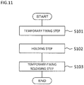
temperature measurement object 5 is a honeycomb sandwich structure is described.FIG. 11 is a flowchart for illustrating the manufacturing method for the temperature measurement system according to the first embodiment of this invention. - First, in Step S101, a temporary fixing step is performed.
FIG. 12 is an explanatory view for illustrating the temporary fixing step ofFIG. 11 . In the temporary fixing step, theoptical fiber 1 is wired to the skin material of the honeycomb sandwich structure being thetemperature measurement object 5, and theoptical fiber 1 is temporarily fixed to the honeycomb sandwichstructure using tapes 11 being temporary fixing members. Further, in the temporary fixing step, theoptical fiber 1 is bent, and the bent portions in theoptical fiber 1 are temporarily fixed to the honeycomb sandwich structure using thetapes 11. - After that, as illustrated in
FIG. 11 , in Step S102, a holding step is performed.FIG. 13 is an explanatory view for illustrating the holding step ofFIG. 11 . In the holding step, the pressingjig 10 holds theoptical fiber 1 through intermediation of theintermediate material 9, and thepressing jig 10 is mounted to thetemperature measurement object 5 such that thepressing jig 10 presses theoptical fiber 1 against thetemperature measurement object 5 through intermediation of theintermediate material 9. - In the holding step, the
optical fiber 1 can expand and contract in the longitudinal direction of theoptical fiber 1 due to the change in the temperature of theoptical fiber 1 with respect to thetemperature measurement object 5 and theintermediate material 9. - After that, as illustrated in
FIG. 11 , in Step S103, a temporary-fixing releasing step is performed. In the temporary-fixing releasing step, as illustrated inFIG. 10 , thetapes 11 are removed from theoptical fiber 1 and thetemperature measurement object 5. With this, the temporary fixing of theoptical fiber 1 to thetemperature measurement object 5 with thetapes 11 is released. In this manner, the manufacture of the temperature measurement system is completed. - As described above, the temperature measurement system according to the first embodiment of this invention includes the
temperature measurement object 5 and theoptical fiber 1 being provided on thetemperature measurement object 5 and having sensitivity to both the temperature and the distortion. - Further, the temperature measurement system includes the
intermediate material 9 in contact with theoptical fiber 1, and thepressing jig 10 that holds theoptical fiber 1 through intermediation of theintermediate material 9 and presses theoptical fiber 1 against thetemperature measurement object 5 through intermediation of theintermediate material 9. Theoptical fiber 1 can expand and contract in the longitudinal direction of theoptical fiber 1 due to the change in the temperature of theoptical fiber 1 with respect to thetemperature measurement object 5 and theintermediate material 9. - With this, the
optical fiber 1 can be freely wired without deteriorating the sensitivity of the temperature measurement, and the temperature of thetemperature measurement object 5 can be measured with high accuracy and high density. In other words, distortion that occurs in thetemperature measurement object 5 can be prevented from being transmitted to theoptical fiber 1, and the responsiveness of the heat transfer from thetemperature measurement object 5 to theoptical fiber 1 can be improved. - In the first embodiment, the configuration of the
optical fiber 1 including theFBG sensor unit 102 is described. However, the present invention is not limited thereto, and other multipointoptical fibers 1 and distributedoptical fibers 1 may be employed. - Further, in the modification example of the first embodiment, the honeycomb sandwich structure is described as an example of the
temperature measurement object 5. However, the present invention is not limited thereto, and thetemperature measurement object 5 can be applied to other satellite-mounted devices. -
FIG. 14 is a perspective view for illustrating a temperature measurement system according to a second embodiment of this invention. In the first embodiment, the configuration in which theFBG sensor unit 102 is covered with thepressing jig 10 is described. In contrast, in the second embodiment, theoptical fiber 1 is held by a pair of shortpressing jigs 10. TheFBG sensor unit 102 is not covered with thepressing jig 10. With this, the configuration of the temperature measurement system is simplified. -
FIG. 15 is a perspective view for illustrating a modification example of the temperature measurement system ofFIG. 14. FIG. 15 is an illustration of a temperature measurement system in a case in which theoptical fiber 1 is bent. Further, inFIG. 15 , thetemperature measurement object 5 is a honeycomb sandwich structure. - In the temperature measurement system according to the first embodiment, the entire
FBG sensor unit 102 of theoptical fiber 1 is covered with thepressing jig 10. In contrast, in the temperature measurement system illustrated in each ofFIG. 14 and FIG. 15 , theoptical fiber 1 is held by the pair of pressingjigs 10 such that theoptical fiber 1 is not separated away from thetemperature measurement object 5. In the temperature measurement system according to the second embodiment, the volume of theintermediate material 9 and thepressing jig 10 is smaller than that of the temperature measurement system according to the first embodiment. Other configurations are the same as those of the first embodiment. - As described above, with the temperature measurement system according to the second embodiment of this invention, each of the pair of pressing
jigs 10 holds theoptical fiber 1 through intermediation of theintermediate material 9. With this, the same effects as those of the first embodiment can be obtained, and as compared to the first embodiment, the configuration of the temperature measurement system can be simplified. -
FIG. 16 is a perspective view for illustrating a temperature measurement system according to a third embodiment of this invention. In the first embodiment, the configuration in which theoptical fiber 1 is arranged between thetemperature measurement object 5 and theintermediate material 9 is described. In contrast, in the third embodiment, a paste-like substance 12 is provided around theoptical fiber 1. - Thus, the paste-
like substance 12 is provided in a gap between theoptical fiber 1 and theintermediate material 9 and a gap between thetemperature measurement object 5 and theintermediate material 9. The paste-like substance 12 adheres to thetemperature measurement object 5, theoptical fiber 1, and theintermediate material 9. - As the paste-
like substance 12, one having an NLGI consistency number of 00 or more and 5 or less is used. An adhesion step of allowing the paste-like substance 12 to adhere to thetemperature measurement object 5 and theoptical fiber 1 is performed after the temporary fixing step and before the holding step. With the holding step, the paste-like substance 12 adheres to theintermediate material 9. -
FIG. 17 is a perspective view for illustrating a modification example of the temperature measurement system ofFIG. 16 . InFIG. 17 , a temperature measurement system in a case in which theoptical fiber 1 is bent is illustrated. Further, inFIG. 17 , thetemperature measurement object 5 is a honeycomb sandwich structure. - In the temperature measurement system according to the first embodiment, the
optical fiber 1 is arranged between thetemperature measurement object 5 and theintermediate material 9. Thus, in the temperature measurement system according to the first embodiment, a gap may be formed by thetemperature measurement object 5, theoptical fiber 1, and theintermediate material 9. In contrast, in the temperature measurement system illustrated in each ofFIG. 16 and FIG. 17 , the paste-like substance 12 is provided around theoptical fiber 1. - The paste-
like substance 12 adheres to thetemperature measurement object 5, theoptical fiber 1, and theintermediate material 9. With this, theoptical fiber 1 is firmly held on thetemperature measurement object 5, and heat is easily transferred from thetemperature measurement object 5 to theoptical fiber 1. Other configurations are the same as those of the first embodiment. The other configurations may be the same as those of the second embodiment. - As described above, the temperature measurement system according to the third embodiment of this invention includes the paste-
like substance 12 which adheres to thetemperature measurement object 5 and theoptical fiber 1. With this, theoptical fiber 1 is firmly held on thetemperature measurement object 5, and heat is easily transferred from thetemperature measurement object 5 to theoptical fiber 1. -
FIG. 18 is a perspective view for illustrating a temperature measurement system according to a fourth embodiment of this invention. In the third embodiment, the configuration in which, after the paste-like substance 12 adheres around theoptical fiber 1, theintermediate material 9 is provided on theoptical fiber 1 is described. In contrast, in the fourth embodiment, a paste-like substance is infiltrated into theintermediate material 9. The paste-like substance in the fourth embodiment is the same as the paste-like substance in the third embodiment. -
FIG. 19 is a perspective view for illustrating a modification example of the temperature measurement system ofFIG. 18 . InFIG. 19 , a temperature measurement system in the case in which theoptical fiber 1 is bent is illustrated. Further, inFIG. 19 , thetemperature measurement object 5 is a honeycomb sandwich structure. - In the temperature measurement system according to the third embodiment, the paste-
like substance 12 adheres to thetemperature measurement object 5 and theoptical fiber 1 so that theoptical fiber 1 is held on thepressing jig 10 through intermediation of theintermediate material 9. In contrast, in the temperature measurement system illustrated in each ofFIG. 18 and FIG. 19 , theintermediate material 9 containing the paste-like substance infiltrated therein covers the periphery of theoptical fiber 1. - With the
intermediate material 9 containing the paste-like substance infiltrated therein, theoptical fiber 1 is firmly held on thetemperature measurement object 5, and heat is easily transferred from thetemperature measurement object 5 to theoptical fiber 1. Other configurations are the same as those of the third embodiment. - As described above, with the temperature measurement system according to the fourth embodiment of this invention, the paste-like substance is infiltrated into the
intermediate material 9. With this, theoptical fiber 1 is firmly held on thetemperature measurement object 5, and heat is easily transferred from thetemperature measurement object 5 to theoptical fiber 1. -
- 1
- optical fiber,
- 2
- optical circulator,
- 3
- ASE light source,
- 4
- spectrum analyzer,
- 5
- temperature measurement object,
- 6
- protective tube,
- 7
- conductive viscous material,
- 8
- casing,
- 9
- intermediate material,
- 10
- pressing jig,
- 11
- tape,
- 12
- paste-like substance,
- 81
- inlet portion,
- 82
- outlet portion,
- 101
- core,
- 102
- FBG sensor unit,
- 103
- cladding,
- 104
- covering portion,
- 105
- cover removed portion
Claims (10)
- A temperature measurement system, comprising:- a temperature measurement object;- an optical fiber provided on the temperature measurement object;- an intermediate material provided on the optical fiber; and- a pressing jig which is provided on the temperature measurement object, and is configured to press the optical fiber against the temperature measurement object through intermediation of the intermediate material,- wherein the optical fiber is expandable and contractible in a longitudinal direction of the optical fiber due to a change in a temperature of the optical fiber with respect to the temperature measurement object and the intermediate material.
- The temperature measurement system according to claim 1,
wherein the intermediate material is formed of a material softer than the pressing jig. - The temperature measurement system according to claim 1 or 2,
wherein the pressing jig is fixed to the temperature measurement object using a pressure-sensitive adhesive, an adhesive, a screw, or a bolt. - The temperature measurement system according to any one of claims 1 to 3, further comprising a paste-like substance which adheres to the temperature measurement object and the optical fiber.
- The temperature measurement system according to any one of claims 1 to 3, wherein the intermediate material contains a paste-like substance infiltrated therein.
- The temperature measurement system according to claim 4 or 5,
wherein the paste-like substance has an NLGI consistency number of 00 or more and 5 or less. - The temperature measurement system according to any one of claims 1 to 6, wherein the temperature measurement object is a honeycomb sandwich structure.
- A manufacturing method for a temperature measurement system, comprising:- a temporary fixing step of temporarily fixing an optical fiber to a temperature measurement object using a temporary fixing member;- a holding step of pressing, by a pressing jig, the optical fiber against the temperature measurement object through intermediation of an intermediate material by mounting the pressing jig to the temperature measurement object after the temporary fixing step; and- a temporary-fixing releasing step of releasing the temporary fixing of the optical fiber to the temperature measurement object by the temporary fixing member after the holding step,- wherein, in the holding step, the optical fiber is expandable and contractible in a longitudinal direction of the optical fiber due to a change in a temperature of the optical fiber with respect to the temperature measurement object and the intermediate material.
- The manufacturing method for a temperature measurement system according to claim 8,
further comprising an adhesion step of allowing a paste-like substance to adhere to the temperature measurement object and the optical fiber. - The manufacturing method for a temperature measurement system according to claim 8,
wherein the intermediate material contains a paste-like substance infiltrated therein.
Applications Claiming Priority (1)
| Application Number | Priority Date | Filing Date | Title |
|---|---|---|---|
| PCT/JP2019/029799 WO2021019678A1 (en) | 2019-07-30 | 2019-07-30 | Temperature measuring system and method for manufacturing same |
Publications (2)
| Publication Number | Publication Date |
|---|---|
| EP4006514A1 true EP4006514A1 (en) | 2022-06-01 |
| EP4006514A4 EP4006514A4 (en) | 2022-08-03 |
Family
ID=70858266
Family Applications (1)
| Application Number | Title | Priority Date | Filing Date |
|---|---|---|---|
| EP19939999.9A Pending EP4006514A4 (en) | 2019-07-30 | 2019-07-30 | Temperature measuring system and method for manufacturing same |
Country Status (5)
| Country | Link |
|---|---|
| US (1) | US20220260429A1 (en) |
| EP (1) | EP4006514A4 (en) |
| JP (1) | JP6704546B1 (en) |
| CN (1) | CN114174790A (en) |
| WO (1) | WO2021019678A1 (en) |
Citations (3)
| Publication number | Priority date | Publication date | Assignee | Title |
|---|---|---|---|---|
| JP2016013667A (en) * | 2014-07-03 | 2016-01-28 | 三菱電機株式会社 | Honey-com sandwich structure and manufacturing method thereof |
| US20160169807A1 (en) * | 2013-09-24 | 2016-06-16 | Fujitsu Limited | Optical fiber cord and abnormality detection system |
| US20190016065A1 (en) * | 2016-10-09 | 2019-01-17 | Shandong University | Composite material packaged fiber grating sensor and manufacturing method thereof |
Family Cites Families (2)
| Publication number | Priority date | Publication date | Assignee | Title |
|---|---|---|---|---|
| JP2002317451A (en) * | 2001-04-23 | 2002-10-31 | Dai Ichi High Frequency Co Ltd | Optical fiber stretching system for observation of ground deformation |
| JP7047366B2 (en) * | 2017-12-15 | 2022-04-05 | 株式会社豊田中央研究所 | Fiber optic sensor |
-
2019
- 2019-07-30 CN CN201980098705.2A patent/CN114174790A/en active Pending
- 2019-07-30 US US17/624,582 patent/US20220260429A1/en active Pending
- 2019-07-30 JP JP2020503069A patent/JP6704546B1/en active Active
- 2019-07-30 EP EP19939999.9A patent/EP4006514A4/en active Pending
- 2019-07-30 WO PCT/JP2019/029799 patent/WO2021019678A1/en unknown
Patent Citations (3)
| Publication number | Priority date | Publication date | Assignee | Title |
|---|---|---|---|---|
| US20160169807A1 (en) * | 2013-09-24 | 2016-06-16 | Fujitsu Limited | Optical fiber cord and abnormality detection system |
| JP2016013667A (en) * | 2014-07-03 | 2016-01-28 | 三菱電機株式会社 | Honey-com sandwich structure and manufacturing method thereof |
| US20190016065A1 (en) * | 2016-10-09 | 2019-01-17 | Shandong University | Composite material packaged fiber grating sensor and manufacturing method thereof |
Non-Patent Citations (1)
| Title |
|---|
| See also references of WO2021019678A1 * |
Also Published As
| Publication number | Publication date |
|---|---|
| WO2021019678A1 (en) | 2021-02-04 |
| EP4006514A4 (en) | 2022-08-03 |
| CN114174790A (en) | 2022-03-11 |
| US20220260429A1 (en) | 2022-08-18 |
| JPWO2021019678A1 (en) | 2021-09-13 |
| JP6704546B1 (en) | 2020-06-03 |
Similar Documents
| Publication | Publication Date | Title |
|---|---|---|
| Ecke et al. | Fibre optic sensor network for spacecraft health monitoring | |
| US6522809B1 (en) | Waveguide grating device and method of controlling Bragg wavelength of waveguide grating | |
| Hampshire et al. | Monitoring the behavior of steel structures using distributed optical fiber sensors | |
| US20010019103A1 (en) | Optical fiber sensor | |
| EP3009808B1 (en) | Honeycomb sandwich structure and production method for honeycomb sandwich structure | |
| EP3425357A1 (en) | Optical fiber temperature sensor and method for manufacturing same | |
| Yi et al. | PDMS-coated no-core fiber interferometer with enhanced sensitivity for temperature monitoring applications | |
| US7050662B2 (en) | Fiber Bragg grating compression sensor system | |
| US7729567B2 (en) | Fiber optic transducer for simultaneous pressure and temperature measurement in fluid flow | |
| Ma et al. | Strain transfer characteristics of surface-attached FBGs in aircraft wing distributed deformation measurement | |
| KR101529610B1 (en) | Apparatus and Sensing System for Fiber Bragg Grating Probes Having Controlled Sensitivity and Method for Sensing and Manufacturing thereof | |
| EP4006514A1 (en) | Temperature measuring system and method for manufacturing same | |
| Lo et al. | Packaging a fiber Bragg grating with metal coating for an athermal design | |
| Mikhailov et al. | Multifunctional fiber-optic sensors for space infrastructure | |
| JP2010025810A (en) | Apparatus and method for predicting oscillation for health monitoring | |
| Du et al. | Fiber Bragg grating sensor | |
| Abad et al. | Fiber optic sensing subsystem for temperature monitoring in space in-flight applications | |
| Zhang et al. | Numerical and experimental studies of high-sensitivity plug-in pressure sensor based on fiber Bragg gratings | |
| Kruzelecky et al. | Fiber-optic sensor demonstrator (FSD) preliminary test results on PROBA-2 | |
| JP6736044B2 (en) | Strain sensor and jig for mounting the strain sensor | |
| JP2006047154A (en) | Fiber-optic temperature sensor and its manufacturing method | |
| Heredero et al. | In-orbit demonstration of fiber optic sensors based on Bragg gratings | |
| Allison et al. | Novel piezoelectric actuators for tuning an optical fiber Bragg grating | |
| Cheng et al. | Multi-parameter Fibre Bragg Grating sensor-array for thermal vacuum cycling test | |
| EP4283251A1 (en) | Gauge carrier, optical fiber displacement sensor, and production method for optical fiber displacement sensor |
Legal Events
| Date | Code | Title | Description |
|---|---|---|---|
| STAA | Information on the status of an ep patent application or granted ep patent |
Free format text: STATUS: THE INTERNATIONAL PUBLICATION HAS BEEN MADE |
|
| PUAI | Public reference made under article 153(3) epc to a published international application that has entered the european phase |
Free format text: ORIGINAL CODE: 0009012 |
|
| STAA | Information on the status of an ep patent application or granted ep patent |
Free format text: STATUS: REQUEST FOR EXAMINATION WAS MADE |
|
| 17P | Request for examination filed |
Effective date: 20220125 |
|
| AK | Designated contracting states |
Kind code of ref document: A1 Designated state(s): AL AT BE BG CH CY CZ DE DK EE ES FI FR GB GR HR HU IE IS IT LI LT LU LV MC MK MT NL NO PL PT RO RS SE SI SK SM TR |
|
| REG | Reference to a national code |
Ref country code: DE Ref legal event code: R079 Free format text: PREVIOUS MAIN CLASS: G01K0011320000 Ipc: G01K0011320600 |
|
| A4 | Supplementary search report drawn up and despatched |
Effective date: 20220704 |
|
| RIC1 | Information provided on ipc code assigned before grant |
Ipc: G01K 1/143 20210101ALI20220628BHEP Ipc: G01K 11/32 20210101ALI20220628BHEP Ipc: G01K 11/3206 20210101AFI20220628BHEP |
|
| DAV | Request for validation of the european patent (deleted) | ||
| DAX | Request for extension of the european patent (deleted) | ||
| GRAP | Despatch of communication of intention to grant a patent |
Free format text: ORIGINAL CODE: EPIDOSNIGR1 |
|
| STAA | Information on the status of an ep patent application or granted ep patent |
Free format text: STATUS: GRANT OF PATENT IS INTENDED |