EP4006512A1 - Detection method, detection apparatus and detection system - Google Patents
Detection method, detection apparatus and detection system Download PDFInfo
- Publication number
- EP4006512A1 EP4006512A1 EP21204540.5A EP21204540A EP4006512A1 EP 4006512 A1 EP4006512 A1 EP 4006512A1 EP 21204540 A EP21204540 A EP 21204540A EP 4006512 A1 EP4006512 A1 EP 4006512A1
- Authority
- EP
- European Patent Office
- Prior art keywords
- thermistor
- electric resistance
- resistance value
- value
- failure
- Prior art date
- Legal status (The legal status is an assumption and is not a legal conclusion. Google has not performed a legal analysis and makes no representation as to the accuracy of the status listed.)
- Pending
Links
Images



Classifications
-
- G—PHYSICS
- G01—MEASURING; TESTING
- G01R—MEASURING ELECTRIC VARIABLES; MEASURING MAGNETIC VARIABLES
- G01R31/00—Arrangements for testing electric properties; Arrangements for locating electric faults; Arrangements for electrical testing characterised by what is being tested not provided for elsewhere
- G01R31/26—Testing of individual semiconductor devices
- G01R31/2642—Testing semiconductor operation lifetime or reliability, e.g. by accelerated life tests
-
- G—PHYSICS
- G01—MEASURING; TESTING
- G01K—MEASURING TEMPERATURE; MEASURING QUANTITY OF HEAT; THERMALLY-SENSITIVE ELEMENTS NOT OTHERWISE PROVIDED FOR
- G01K15/00—Testing or calibrating of thermometers
-
- G—PHYSICS
- G01—MEASURING; TESTING
- G01K—MEASURING TEMPERATURE; MEASURING QUANTITY OF HEAT; THERMALLY-SENSITIVE ELEMENTS NOT OTHERWISE PROVIDED FOR
- G01K3/00—Thermometers giving results other than momentary value of temperature
- G01K3/08—Thermometers giving results other than momentary value of temperature giving differences of values; giving differentiated values
- G01K3/10—Thermometers giving results other than momentary value of temperature giving differences of values; giving differentiated values in respect of time, e.g. reacting only to a quick change of temperature
-
- G—PHYSICS
- G01—MEASURING; TESTING
- G01K—MEASURING TEMPERATURE; MEASURING QUANTITY OF HEAT; THERMALLY-SENSITIVE ELEMENTS NOT OTHERWISE PROVIDED FOR
- G01K15/00—Testing or calibrating of thermometers
- G01K15/007—Testing
-
- G—PHYSICS
- G01—MEASURING; TESTING
- G01K—MEASURING TEMPERATURE; MEASURING QUANTITY OF HEAT; THERMALLY-SENSITIVE ELEMENTS NOT OTHERWISE PROVIDED FOR
- G01K7/00—Measuring temperature based on the use of electric or magnetic elements directly sensitive to heat ; Power supply therefor, e.g. using thermoelectric elements
- G01K7/16—Measuring temperature based on the use of electric or magnetic elements directly sensitive to heat ; Power supply therefor, e.g. using thermoelectric elements using resistive elements
- G01K7/22—Measuring temperature based on the use of electric or magnetic elements directly sensitive to heat ; Power supply therefor, e.g. using thermoelectric elements using resistive elements the element being a non-linear resistance, e.g. thermistor
-
- G—PHYSICS
- G01—MEASURING; TESTING
- G01R—MEASURING ELECTRIC VARIABLES; MEASURING MAGNETIC VARIABLES
- G01R27/00—Arrangements for measuring resistance, reactance, impedance, or electric characteristics derived therefrom
- G01R27/02—Measuring real or complex resistance, reactance, impedance, or other two-pole characteristics derived therefrom, e.g. time constant
-
- G—PHYSICS
- G01—MEASURING; TESTING
- G01R—MEASURING ELECTRIC VARIABLES; MEASURING MAGNETIC VARIABLES
- G01R31/00—Arrangements for testing electric properties; Arrangements for locating electric faults; Arrangements for electrical testing characterised by what is being tested not provided for elsewhere
- G01R31/003—Environmental or reliability tests
-
- G—PHYSICS
- G01—MEASURING; TESTING
- G01R—MEASURING ELECTRIC VARIABLES; MEASURING MAGNETIC VARIABLES
- G01R31/00—Arrangements for testing electric properties; Arrangements for locating electric faults; Arrangements for electrical testing characterised by what is being tested not provided for elsewhere
- G01R31/26—Testing of individual semiconductor devices
- G01R31/2601—Apparatus or methods therefor
Definitions
- the present disclosure relates to the technique for detecting a failure of a thermistor.
- Japanese Patent Laying-Open No. 2000-171309 describes the technique for housing a first thermistor and a second thermistor having different temperature output characteristics in a single package, measuring voltage values of both of the thermistors, and determining the possibility of a failure of the thermistors by using the measured voltages and a prescribed temperature map.
- failure/no-failure determination has been conventionally made using an electric resistance value of a thermistor in a certain test environment. That is, if the electric resistance value of the thermistor is normal when a current is applied, the thermistor is determined as non-faulty. Therefore, when failure/no-failure determination is made of a thermistor that basically operates normally but shows an abnormal electric resistance value momentarily, the thermistor cannot in some cases be detected as faulty in the conventional test.
- An object of the present disclosure is to provide a detection method that makes it easier to detect, as faulty, a thermistor showing an abnormal electric resistance value momentarily.
- a detection method for detecting a failure of a thermistor includes: applying a load to the thermistor over time; measuring a physical property value of the thermistor at least at a first time and a second time during a time period in which the load is being applied to the thermistor; and detecting the failure of the thermistor based on first data indicating the physical property value of the thermistor measured at the first time and second data indicating the physical property value of the thermistor measured at the second time.
- a detection apparatus that detects a failure of a thermistor includes: a load unit that applies a load to the thermistor over time; a measurement unit that measures a physical property value of the thermistor at least at a first time and a second time during a time period in which the load is being applied to the thermistor; and a detection unit that detects the failure of the thermistor based on first data indicating the physical property value of the thermistor measured at the first time and second data indicating the physical property value of the thermistor measured at the second time.
- a detection system that detects a failure of a thermistor includes: a load unit that applies a load to the thermistor over time; a measurement unit that measures a physical property value of the thermistor at least at a first time and a second time during a time period in which the load is being applied to the thermistor; and a detection unit that detects the failure of the thermistor based on first data indicating the physical property value of the thermistor measured at the first time and second data indicating the physical property value of the thermistor measured at the second time.
- Fig. 1 schematically shows an example configuration of a detection apparatus 100 according to a first embodiment.
- Detection apparatus 100 is an apparatus that detects a failure of a thermistor TH that is a detection target. Examples of the failure of thermistor TH include a contact failure in an internal circuit of thermistor TH, and the like.
- Fig. 1 shows a state in which thermistor TH is connected to detection apparatus 100.
- Thermistor TH is a negative temperature coefficient (NTC) thermistor using a phenomenon in which an electric resistance value of thermistor TH increases as a temperature of thermistor TH decreases.
- NTC negative temperature coefficient
- the electric resistance value of thermistor TH changes.
- the electric resistance value of thermistor TH is 800 k ⁇ .
- the electric resistance value of thermistor TH is 6.85 k ⁇ .
- thermistor TH may be a positive temperature coefficient (PTC) thermistor.
- Detection apparatus 100 includes a measurement unit 10, a controller 20 and a cooling unit 30. Detection apparatus 100 may not be formed as an integrated apparatus. Specifically, measurement unit 10, controller 20 and cooling unit 30 may be provided separately and connected to one another through a wired or wireless network, to thereby form a detection system.
- Measurement unit 10 measures the electric resistance value of thermistor TH. Measurement unit 10 is electrically connected to thermistor TH. Measurement unit 10 indirectly measures the electric resistance value by applying a certain voltage to thermistor TH and measuring a current value. That is, measurement unit 10 measures a value of a current flowing through thermistor TH.
- Controller 20 includes a central processing unit (CPU) 21, a random access memory (RAM) 22 and a read only memory (ROM) 23.
- CPU 21 performs a program for controlling the operation of detection apparatus 100.
- RAM 22 stores an application program performed by CPU 21, and referenced data.
- RAM 22 is implemented by a static random access memory (SRAM), a dynamic random access memory (DRAM), or the like.
- ROM 23 stores a program such as an operating system (OS) performed by CPU 21.
- OS operating system
- ROM 23 is implemented by an erasable programmable ROM (EPROM), an electrically erasable programmable ROM (EEPROM), a flash memory, or the like.
- EPROM erasable programmable ROM
- EEPROM electrically erasable programmable ROM
- flash memory or the like.
- controller 20 may be implemented by a circuit element such as at least one embedded CPU, at least one application specific integrated circuit (ASIC) or at least one field programmable gate array (FPGA). Furthermore, in another aspect, controller 20 may be implemented by a combination of two or more circuit elements.
- ASIC application specific integrated circuit
- FPGA field programmable gate array
- Cooling unit 30 cools thermistor TH connected to measurement unit 10.
- Cooling unit 30 may, for example, cool thermistor TH by using a chemical reaction, or may be an evaporator or the like of a refrigeration cycle apparatus.
- cooling process the process of cooling thermistor TH by cooling unit 30 will be simply referred to as "cooling process”.
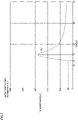
- Fig. 2 shows transition of an electric resistance value of a thermistor TH1.
- Thermistor TH1 is a thermistor that operates normally.
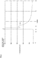
- Fig. 3 shows transition of an electric resistance value of a thermistor TH2.
- Thermistor TH2 is a thermistor having such a failure that an internal circuit enters an open state momentarily.
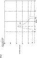
- Fig. 4 shows transition of an electric resistance value of a thermistor TH3.
- Thermistor TH3 is a thermistor having such a failure that an internal circuit enters a short-circuited state momentarily.
- the transition of the electric resistance value when thermistor TH that is a detection target is cooled in the case where thermistor TH that is a detection target is normal, and the transition of the electric resistance value when thermistor TH that is a detection target is cooled in the case where thermistor TH that is a detection target is faulty will be separately described below with reference to Figs. 2 to 4 .
- the vertical axis in each of Figs. 2 to 4 indicates the electric resistance value of thermistor TH that is a detection target.
- the horizontal axis in each of Figs. 2 to 4 indicates the elapsed time from the start of measurement of the electric resistance value.
- Measurement unit 10 measures the electric resistance value for forty seconds.
- each of Figs. 2 to 4 shows a measurement result when, during the measurement time period, the cooling process is started twelve seconds after the start of measurement of the electric resistance value, and three seconds after that, i.e., fifteen seconds after the start of measurement of the electric resistance value, the cooling process is ended.
- each of thermistor TH1 to thermistor TH3 that are detection targets is a negative temperature coefficient (NTC) thermistor in which the electric resistance value increases as the temperature decreases.
- NTC negative temperature coefficient
- Thermistor TH1 that operates normally will be described with reference to Fig. 2 .
- the electric resistance value of thermistor TH1 starts to increase when twelve seconds have elapsed from the start of measurement of the electric resistance value. That is, cooling unit 30 starts the cooling process for thermistor TH1 when twelve seconds have elapsed. It can be seen that the electric resistance value of thermistor TH1 before the start of the cooling process is 30 k ⁇ .
- the cooling process for thermistor TH1 stops when fifteen seconds have elapsed.
- the temperature of thermistor TH1 increases gradually.
- the electric resistance value of thermistor TH1 decreases gradually.
- the electric resistance value of thermistor TH1 increases to about 280 k ⁇ for three seconds after the start of the cooling process.
- the electric resistance value of thermistor TH1 does not decrease to 30 k ⁇ after the cooling process is stopped. That is, a degree of increase in the electric resistance value of thermistor TH1 is steeper than a degree of decrease in the electric resistance value of thermistor TH1.
- a curve RL2 shown in Fig. 3 is different from curve RL1 shown in Fig. 2 .
- thermistor TH2 twelve seconds after the start of measurement, i.e., shortly after the start of the cooling process, the electric resistance value of thermistor TH2 increases impulsively and thermistor TH2 enters the open state. For example, a portion where connection of the internal circuit of thermistor TH2 is insufficient may be affected by cooling and enter the open state momentarily.
- curve RL2 indicating the electric resistance value of thermistor TH2 increases steeply as shown in Fig. 3 .
- time period P1 the electric resistance value of thermistor TH2 returns to a normal value.
- thermistor TH2 in Fig. 3 does not normally operate momentarily and has an operation failure.
- the electric resistance value of thermistor TH2 is abnormal only during time period P1.
- Fig. 3 illustrates time period P1 as a time period of approximately one second for easy understanding of the description, time period P1 is a very short time period shorter than one second.
- a curve RL3 shown in Fig. 4 is different from curve RL1 shown in Fig. 2 .
- the cooling process is also ended fifteen seconds after the start of measurement of the electric resistance value.
- the electric resistance value of thermistor TH3 decreases gently for a while.
- the electric resistance value of thermistor TH3 shows a short-circuited state of thermistor TH3 momentarily, and then, returns to a normal electric resistance value.
- thermistor TH3 in Fig. 4 does not normally operate momentarily and has an operation failure. That is, the electric resistance value of thermistor TH3 is abnormal only during time period P2.
- Fig. 4 illustrates time period P2 as a time period of approximately one second for easy understanding of the description, time period P2 is a very short time period shorter than one second.
- the internal circuit may enter an open state or a short-circuited state momentarily, when a load such as the cooling process is applied to thermistor TH over time.
- a load such as the cooling process
- Such a failure of thermistor TH that occurs momentarily at the time of application of the load cannot be detected using a method for temporarily measuring the electric resistance value of thermistor TH without applying the load.
- the first embodiment provides a detection method for detecting a potential failure of thermistor TH by focusing attention on characteristics of thermistor TH.
- Fig. 5 is a flowchart showing an example process performed when detection apparatus 100 according to the first embodiment performs failure detection of thermistor TH that is a detection target.
- Detection apparatus 100 according to the present embodiment detects an abnormality of the electric resistance value of thermistor TH shown in each of Figs. 3 and 4 by performing the flowchart shown in Fig. 5 .
- the flowchart shown in Fig. 5 is performed by controller 20 of detection apparatus 100.
- the flowchart in Fig. 5 performed by controller 20 may be simply referred to as "detection method".
- controller 20 causes cooling unit 30 to start the cooling process of cooling thermistor TH (step S101). After starting the cooling process, cooling unit 30 continues the cooling process for a cooling end time period tr. Cooling end time period tr is, for example, three seconds, five seconds, ten seconds or the like.
- Controller 20 causes measurement unit 10 to measure the electric resistance value of thermistor TH (step S102).
- measurement unit 10 transmits the measured electric resistance value of thermistor TH to controller 20 as data.
- controller 20 determines whether or not a prescribed time period t has elapsed since measurement unit 10 measured the electric resistance value (step S103).
- the process in the flowchart shown in Fig. 5 is returned from step S106 or step S112 to step S103. That is, controller 20 repeatedly performs the process starting from step S103, until a prescribed condition is satisfied.
- step S103 the process performed for the first time
- second round of the process the process performed for the second time
- third round of the process the process performed for the third time
- prescribed time period t refers to a time period indicating an interval of measurement of the electric resistance value, and is predetermined. That is, until the prescribed condition is satisfied, controller 20 causes measurement unit 10 to measure the electric resistance value of thermistor TH that is a detection target, every time prescribed time period t elapses.
- controller 20 determines that prescribed time period t has not yet elapsed after the process in step S102 (NO in step S103), controller 20 causes the process to remain in step S103. While the first round of the process remains in step S103, the temperature of thermistor TH continues to decrease due to the cooling process.
- the cooling process in the first embodiment corresponds to "load" in the present disclosure.
- controller 20 determines that prescribed time period t has elapsed after the process in step S102 (YES in step S103), controller 20 causes measurement unit 10 to again measure the electric resistance value of thermistor TH (step S104).
- step S104 measurement unit 10 transmits the measured electric resistance value of thermistor TH to controller 20 as data.
- the electric resistance value of thermistor TH changes over time. Therefore, the data about the electric resistance value received by controller 20 in step S102 corresponds to data indicating the electric resistance value before change, and the data in step S104 in the first round of the process corresponds to data indicating the electric resistance value after change.
- the data indicating the electric resistance value before change corresponds to "first data” in the present disclosure.
- the data indicating the electric resistance value after change corresponds to "second data” in the present disclosure.
- Controller 20 calculates an amount of change in the electric resistance value using the first data and the second data (step S105). That is, controller 20 calculates the amount of change in the electric resistance value per prescribed time period t. Controller 20 causes at least one of the RAM and the ROM to store the calculated amount of change as data.
- the amount of change refers to a difference between the electric resistance value before change and the electric resistance value after change.
- the time at which the electric resistance value before change is measured corresponds to "first time” in the present disclosure.
- the time at which the electric resistance value after change is measured corresponds to "second time” in the present disclosure.
- the electric resistance value of thermistor TH corresponds to "physical property value of the thermistor" in the present disclosure.
- Controller 20 determines whether or not four or more pieces of data about the amount of change calculated in step S105 are stored (step S106). When controller 20 determines that four or more pieces of data about the amount of change are not stored (NO in step S106), controller 20 returns the process to step S103. At this time, controller 20 determines that the first round of the process has ended and the second round of the process has started, and increments the counter. After prescribed time period t elapses, controller 20 causes measurement unit 10 to again measure the electric resistance value (step S 104).
- Controller 20 calculates the amount of change in the electric resistance value by using the data about the electric resistance value in step S104 in the first round of the process as data before change, and the data about the electric resistance value in step S104 in the second round of the process as data after change (step S105). Thereafter, controller 20 returns the process from step S106 to step S103 and starts the third round of the process. In this way, controller 20 repeats the process until four or more pieces of data about the amount of change are stored.
- controller 20 determines that four or more pieces of data about the amount of change are stored (YES in step S106)
- controller 20 calculates a moving average value based on the four pieces of data about the amount of change in the electric resistance value (step S107).
- the moving average value refers to a value calculated using a moving average method.
- the moving average method refers to a method for smoothing time-series data by dividing a sum of pieces of changing data within a range by the number of the pieces of data. By smoothing the time-series data, erroneous detection in which thermistor TH is determined as abnormal although thermistor TH is normal can be prevented in detection apparatus 100. Details about the moving average will be described below. Controller 20 calculates the moving average value based on the four pieces of data about the amount of change in the electric resistance value per prescribed time period t.
- the number of pieces of data for calculating the moving average value may be any number other than four.
- Controller 20 determines whether or not the calculated moving average value of the amount of change in the electric resistance value is larger than a reference value (step S108).
- the reference value refers to a predetermined value for determining that thermistor TH is faulty when the calculated moving average value of the amount of change is larger than the reference value.
- the reference value indicates an absolute value of the amount of change. That is, the calculated amount of change being larger than the reference value means that the electric resistance value of thermistor TH increases or decreases steeply.
- controller 20 determines whether or not cooling end time period tr has elapsed from the start of the cooling process (step S110).
- controller 20 determines that cooling end time period tr has elapsed (YES in step S110)
- controller 20 stops the cooling process started in step S101 (step S111), and moves the process to step S112.
- controller 20 determines that cooling end time period tr has not elapsed (NO in step S110), controller 20 does not stop the cooling process started in step S101, and moves the process to step S112.
- Detection end time period td refers to a maximum time period in which the detection process is performed on thermistor TH that is a detection target, after the start of the cooling process.
- Detection end time period td is predetermined, and is, for example, thirty seconds from the start of measurement by measurement unit 10.
- Detection end time period td may be any time period other than thirty seconds, and may be, for example, forty seconds.
- controller 20 determines that detection end time period td has elapsed from the start of the cooling process (YES in step S108). That is, when controller 20 cannot detect a failure of thermistor TH by the time detection end time period td elapses, controller 20 determines that thermistor TH that is a detection target is not faulty.
- controller 20 determines that detection end time period td has not elapsed (NO in step S112)
- controller 20 returns the process to step S103. Thereafter, controller 20 determines whether or not prescribed time period t has elapsed from the last measurement of the electric resistance value by measurement unit 10 (step S103).
- controller 20 determines that prescribed time period t has elapsed (YES in step S103), controller 20 causes measurement unit 10 to again measure the electric resistance value of thermistor TH (step S104).
- controller 20 calculates an amount of change from the electric resistance value of thermistor TH before prescribed time period t elapses to the electric resistance value of thermistor TH after prescribed time period t elapses (step S105). Controller 20 calculates a moving average value of the calculated amount of change in the electric resistance value (step S107), and determines whether or not the moving average value is larger than the reference value (step S108).
- controller 20 repeatedly performs the process from step S103 until a failure of thermistor TH is detected or detection end time period td elapses. That is, controller 20 causes measurement unit 10 to measure the electric resistance value of thermistor TH at every prescribed time period t, and calculates the amount of change from the previously measured electric resistance value.
- controller 20 determines that the electric resistance value of thermistor TH is abnormal, and detects that thermistor TH is faulty.
- controller 20 may calculate a failure of the thermistor by comparing the amount of change in the electric resistance value with the reference value.
- Step S101 in Fig. 5 corresponds to "applying a load” in the present disclosure.
- Steps S102 and S104 in Fig. 5 correspond to "measuring a physical property value of the thermistor” in the present disclosure.
- Step S108 in Fig. 5 corresponds to "detecting the failure” in the present disclosure.
- Controller 20 in step S108 functions as “detection unit” in the present disclosure.
- Fig. 6 shows transition of an electric resistance value and a moving average value of a thermistor TH4.
- Thermistor TH4 is a normal thermistor that does not have a potential failure.
- the graph shown in Fig. 6 is a graph obtained by applying the detection process described with reference to Fig. 5
- the horizontal axis indicates the elapsed time from the start of measurement of thermistor TH4 by measurement unit 10.
- the left vertical axis and a curve RL4 indicate transition of the electric resistance value of thermistor TH4. Referring to the left vertical axis and curve RL4, it can be seen that the electric resistance value of thermistor TH4 is 30 k ⁇ until ten seconds elapse from the start of measurement by measurement unit 10.
- the right vertical axis and a curve SL1 indicate the moving average value of the amount of change in the electric resistance value at every prescribed time period t.
- curve RL4 the electric resistance value of thermistor TH4 increases after ten seconds elapse from the start of the cooling process. Therefore, curve SL1 indicating the moving average value of the amount of change in the electric resistance value also increases after ten seconds elapse.
- Detection apparatus 100 sets ten seconds from the start of measurement of thermistor TH4 by measurement unit 10 as a preparation time period and starts the flowchart shown in Fig. 5 when ten seconds elapse. That is, cooling unit 30 starts the cooling process when ten seconds elapse, and stops the cooling process when fourteen seconds elapse. In the example shown in Fig. 6 , cooling unit 30 stops the cooling process when four seconds elapse after the start of the cooling process.
- Controller 20 receives the electric resistance value of thermistor TH4 from measurement unit 10 at every prescribed time period t. Based on the received electric resistance value, controller 20 calculates a curve RL approximately. That is, curve RL shown in Fig. 6 approximately illustrates a plurality of electric resistance values at every prescribed time period t as a curve.
- a reference value ThL refers to an amount of change per predetermined prescribed time period t, and refers to a reference value for determining whether or not thermistor TH4 is faulty.
- reference value ThL is determined as an amount of change of 200 k ⁇ per prescribed time period t.
- controller 20 compares a moving average value of an amount of decrease in the electric resistance value with reference value ThL. That is, controller 20 does not use an amount of increase in the electric resistance value as a comparison target for detecting a failure of thermistor TH. That is, when the moving average value of the amount of change is below -200 k ⁇ per prescribed time period t, controller 20 detects that thermistor TH is faulty.
- the amount of decrease in the electric resistance value may be referred to as "amount of change in a negative direction”
- the amount of increase in the electric resistance value may be referred to as "amount of change in a positive direction”.
- thermistor TH4 that is a detection target in Fig. 6 operates normally. Therefore, curve SL1 does not fall below reference value ThL throughout the measurement time period. Detection apparatus 100 according to the first embodiment determines that thermistor TH4 is not faulty.
- controller 20 may calculate an approximate curve of curve RL1 as a function.
- controller 20 calculates curve SL1 as a derivative function of curve RL1. That is, curve SL1 indicates the amount of change in the electric resistance value in a very small amount of time of curve RL1, which is an approximate curve.
- Reference value ThL is a predetermined derivative coefficient.
- Fig. 7 shows transition of an electric resistance value and a moving average value of a thermistor TH5.
- Thermistor TH5 is a thermistor having such a failure that an internal circuit enters an open state momentarily.
- the graph shown in Fig. 7 is a graph obtained by applying the detection process described with reference to Fig. 5 .
- the horizontal axis indicates the elapsed time from the start of measurement of thermistor TH5 by measurement unit 10.
- the left vertical axis and a curve RL5 indicate transition of the electric resistance value of thermistor TH5.
- the right vertical axis and a curve SL2 indicate the moving average value of the amount of change in the electric resistance value at every prescribed time period t.
- curve RL5 shows the electric resistance value exceeding 800 k ⁇ during a time period P3. That is, an electric circuit including thermistor TH5 is in an open state during time period P3.
- controller 20 calculates curve SL2 indicating the moving average value of the amount of change in the electric resistance value.
- curve SL2 indicating the moving average value of the amount of change in the electric resistance value.
- curve SL2 indicating the moving average value of the amount of change in the electric resistance value also steeply increases and decreases at the same time. Therefore, during a time period A1, the moving average value of the amount of change indicated by curve SL2 is below reference value ThL. During time period A1, the amount of change in the negative direction in the electric resistance value is larger than 200 k ⁇ . per prescribed time period t, which is reference value ThL.
- controller 20 can detect that thermistor TH5, which is a target of detection by detection apparatus 100, is faulty.
- the process may be ended when the amount of change in the electric resistance value indicated by curve SL2 falls below reference value ThL.
- Fig. 7 illustrates curve RL5 and curve SL2 when measurement unit 10 continues to measure the electric resistance value after time period A1.
- the possibility of detecting a failure of thermistor TH5 even when time period P3 is very short is enhanced, as compared with the case of focusing attention only on the electric resistance value without taking the amount of change into consideration. That is, since time period P3 is shorter than prescribed time period t, a failure of thermistor TH5 cannot be detected when the amount of change in the electric resistance value is not taken into consideration, if measurement unit 10 cannot measure the electric resistance value of thermistor TH5 during time period P3.
- thermistor TH5 that is a target of detection by detection apparatus 100 in Fig. 7 repeats steep increases and decreases in the electric resistance value sporadically during time periods P4, P5 and P6.
- the electric resistance value of thermistor TH5 repeats steep increases and decreases, as compared with the electric resistance value of normal thermistor TH1 shown in Fig. 2 .
- the sporadic steep increases and decreases in the electric resistance value, which occur during time periods A2, A3, A4, A5, and A6 and do not cause the electric circuit including thermistor TH5 to enter the open state, can also be detected as a failure of thermistor TH5.
- the load applied to thermistor TH5 is the cooling process, and thus, only the moving average value in the negative direction in the amount of change is compared with reference value ThL.
- controller 20 does not include, in a comparison target, the moving average value in the positive direction in the amount of change. This is because the amount of change in the electric resistance value is steeper when the cooling process is performed by cooling unit 30 and thereby the temperature of thermistor TH5 decreases, as compared with when the cooling process is stopped and thereby the temperature of thermistor TH5 increases.
- the electric resistance value of thermistor TH5 increases steeply. This is because the amount of change in the increasing direction in the electric resistance value of thermistor TH5 is larger, as compared with the case in which after the cooling process is stopped, natural convection causes heat exchange for the air around thermistor TH and thereby the temperature of thermistor TH5 increases gradually.
- a failure of thermistor TH5 is detected based on the condition of whether or not the calculated amount of change in the negative direction in the electric resistance value is larger than reference value ThL. If the calculated amount of change in the positive direction in the electric resistance value is compared with reference value ThL, there is a higher possibility that controller 20 erroneously detects the steep increase in the electric resistance value caused by the cooling process by cooling unit 30 as a failure of thermistor TH5.
- a failure of thermistor TH5 is detected based on the condition of whether or not the amount of change in the negative direction in the electric resistance value is larger than reference value ThL, thereby preventing the steep increase in the electric resistance value caused by the cooling process by cooling unit 30 from being erroneously detected as a failure of thermistor TH5.
- Fig. 7 shows the example in which measurement unit 10 measures the electric resistance value throughout the time period from the start of measurement by measurement unit 10 to detection end time period td.
- controller 20 may stop the process when controller 20 detects an abnormality of thermistor TH5 during time period A1.
- Fig. 8 shows an example in which an amount of change in an electric resistance value increases steeply in a thermistor TH6 that operates normally.
- the vertical axis in Fig. 8 indicates the electric resistance value of thermistor TH6.
- the horizontal axis in Fig. 8 indicates the elapsed time from the start of measurement by measurement unit 10. The advantages of calculating the amount of change in the electric resistance value and then calculating the moving average value in detection apparatus 100 will be described below.
- thermistor TH6 that is a target of detection by detection apparatus 100 is a thermistor that operates normally. Therefore, the electric resistance value of thermistor TH6 measured by measurement unit 10 does not show an abnormal value as in Fig. 3 or Fig. 4 . That is, an electric circuit including thermistor TH6 does not enter an open state or a short-circuited state.
- the electric resistance value of thermistor TH6 measured by measurement unit 10 does not repeat increases and decreases sporadically as in time periods P4, P5 and P6 in Fig. 7 .
- the amount of change in the electric resistance value of thermistor TH6 is relatively gentle until forty seconds have elapsed since thermistor TH6 was connected to measurement unit 10.
- the shape of curve RL5 may have more or less unevenness. Due to such unevenness in region S1, the amount of change may be determined as large, when attention is focused on the amount of change in a short time period.
- Fig. 9 shows a moving average value of the amount of change per prescribed time period t in the electric resistance value in Fig. 8 .
- Controller 20 calculates the amount of change in the electric resistance value at every prescribed time period t.
- controller 20 calculates a moving average value of the calculated amount of change per prescribed time period t. As a result, controller 20 obtains a curve SL3 as transition of the moving average value of the amount of change per prescribed time period t. By calculating the moving average value, curve SL3 is smoothed. That is, curve SL3 becomes gentle.
- thermistor TH6 that is a detection target operates normally, and thus, the moving average value of the amount of change per prescribed time period t does not become larger than reference value ThL in the negative direction by the time detection end time period td elapses. Therefore, controller 20 determines that thermistor TH6 is not faulty.
- Fig. 10 is a graph showing an amount of change in the electric resistance value when the moving average value is not calculated.
- a thermistor that is a detection target in Fig. 10 is the same as thermistor TH6 that is a detection target in Fig. 9 .
- a curve SL4 shown in Fig. 10 is a curve indicating an amount of change per prescribed time period t before calculating the moving average value indicated by curve SL3 in Fig. 9 . That is, curve SL4 is a curve before calculating the moving average value indicated by curve SL3. Therefore, curve SL4 is not smoothed.
- a region S2 indicates the amount of change in the electric resistance value in region S1 in Fig. 8 .
- the amount of change in the electric resistance value is larger than reference value ThL. That is, when the moving average value is not calculated, controller 20 calculates the unevenness in region S1 as a steep change.
- controller 20 determines the more or less unevenness of the shape of curve RL5 in region S1 in Fig. 8 as an amount of steep change. As a result, controller 20 erroneously detects thermistor TH6 as faulty, although thermistor TH6 operates normally. Therefore, in the first embodiment, the moving average method is used in order to prevent erroneous detection of a failure.
- the cooling process is performed as a method for applying a load to thermistor TH that is a detection target.
- the method for applying a load to thermistor TH is not limited to the cooling process.
- Fig. 11 schematically shows an example configuration of detection apparatus 100A according to the second embodiment that detects a failure of thermistor TH.
- Detection apparatus 100A includes a heating unit 30A.
- Heating unit 30A blows hot air into thermistor TH that is a detection target. As a result, the temperature of thermistor TH increases.
- Heating unit 30A includes a heater and a blower, for example.
- heating unit 30A may include only a heater.
- heating process in the second embodiment corresponds to "load" in the present disclosure.
- a reference value ThH is predetermined.
- Reference value ThH is, for example, an amount of change of 150 k ⁇ per prescribed time period t.
- controller 20 compares the moving average value of the amount of change in the positive direction with reference value ThH. That is, controller 20 in the second embodiment does not include, in a comparison target, the moving average value of the amount of change in the negative direction.
- Fig. 12 shows transition of an electric resistance value and a moving average value of a thermistor TH7.
- Thermistor TH7 is a normal thermistor that does not have a potential failure.
- heating unit 30A starts to blow hot air when ten seconds elapse from the start of measurement of thermistor TH7 by measurement unit 10.
- the electric resistance value of thermistor TH7 decreases as the temperature increases.
- a curve RL6 indicates the electric resistance value of thermistor TH7.
- a curve SL5 indicates the moving average value of the amount of change in the electric resistance value of thermistor TH7.
- the electric resistance value of thermistor TH7 does not show an abnormal value as in Fig. 3 or Fig. 4 .
- the moving average value of the amount of change in the electric resistance value of thermistor TH7 indicated by curve SL5 is approximately within a range of ⁇ 10 k ⁇ to 10 k ⁇ . Therefore, the moving average value of the amount of change does not exceed reference value ThH, which is the amount of change of 150 k ⁇ , and thus, controller 20 determines that thermistor TH7 is not faulty.
- Fig. 13 shows transition of an electric resistance value and a moving average value of a thermistor TH8.
- Thermistor TH8 is a thermistor having such a failure that an internal circuit enters an open state momentarily.
- a curve RL7 indicates the electric resistance value of thermistor TH8.
- a curve SL6 indicates the moving average value of the amount of change in the electric resistance value of thermistor TH8. In Fig. 13 , during time periods P7, P8 and P9, the electric resistance value of thermistor TH8 increases steeply and the internal circuit of thermistor TH8 enters the open state
- the moving average value of the amount of change in the positive direction in the electric resistance value of thermistor TH8 indicated by curve SL6 is larger than reference value ThH. That is, the moving average value of the amount of change in the electric resistance value is equal to or larger than 150 k ⁇ per prescribed time period t.
- controller 20 can detect that thermistor TH8 is faulty.
- the load applied to thermistor TH8 is the heating process, and thus, controller 20 compares the amount of change in the positive direction with reference value Th.
- controller 20 compares the amount of change in the positive direction with reference value Th.
- a failure of thermistor TH8 is detected based on the condition of whether or not the calculated amount of change in the positive direction in the electric resistance value is larger than reference value ThH.
- Controller 20 may stop the process when controller 20 detects an abnormality for the first time during time period P7, or may stop the process when controller 20 detects an abnormality the predetermined number of times. In Fig. 13 , controller 20 stops measurement by measurement unit 10 after time period P9 elapses.
- the load applied to thermistor TH that is a detection target is not limited to changing the temperature of thermistor TH, and may be providing vibrations to thermistor TH. Providing vibrations corresponds to "load" in the present disclosure.
- Controller 20 determines whether or not the moving average value of the amount of change in the electric resistance value becomes larger than the reference value during a time period in which vibrations are being provided to thermistor TH, and thereby, controller 20 can detect a failure.
- a detection method for detecting a failure of a thermistor includes: applying a load including a cooling process, a heating process and vibrations to the thermistor over time; measuring a physical property value of the thermistor at least at a first time and a second time during a time period in which the load is being applied to the thermistor; and detecting the failure of the thermistor based on first data indicating the physical property value of the thermistor measured at the first time and second data indicating the physical property value of the thermistor measured at the second time.
- the physical property value of the thermistor is measured at least at the first time and the second time, of the time period in which the load is being applied to the thermistor.
- detecting the failure of the thermistor includes: calculating an amount of change in the physical property value per prescribed time period t, based on a difference between the physical property value indicated by the first data and the physical property value indicated by the second data, and a difference between the first time and the second time; and detecting the failure of the thermistor by comparing the amount of change in the physical property value per prescribed time period t with a reference value.
- detecting the failure of the thermistor includes detecting the failure of the thermistor by comparing a moving average value of the amount of change in the physical property value with a reference value.
- a temperature of the thermistor is changed.
- the physical property value is an electric resistance value of the thermistor.
- an amount of decrease in the electric resistance value, of the amount of change in the physical property value is compared with a reference value, when the temperature of the thermistor is decreased in applying the load.
- an amount of increase in the electric resistance value, of the amount of change in the physical property value is compared with a reference value, when the temperature of the thermistor is increased in applying the load.
- vibrations are provided to the thermi stor.
- Detection apparatus 100 that detects a failure of a thermistor includes: cooling unit 30 or heating unit 30A that applies a load to the thermistor over time; measurement unit 10 that measures a physical property value of the thermistor at least at a first time and a second time during a time period in which the load is being applied to the thermistor; and a detection unit that detects the failure of the thermistor based on first data indicating the physical property value of the thermistor measured at the first time and second data indicating the physical property value of the thermistor measured at the second time.
- a detection system that detects a failure of a thermistor includes: cooling unit 30 or heating unit 30A that applies a load to the thermistor over time; measurement unit 10 that measures a physical property value of the thermistor at least at a first time and a second time during a time period in which the load is being applied to the thermistor; and a detection unit that detects the failure of the thermistor based on first data indicating the physical property value of the thermistor measured at the first time and second data indicating the physical property value of the thermistor measured at the second time.
Landscapes
- Physics & Mathematics (AREA)
- General Physics & Mathematics (AREA)
- Nonlinear Science (AREA)
- Engineering & Computer Science (AREA)
- Environmental & Geological Engineering (AREA)
- Testing Electric Properties And Detecting Electric Faults (AREA)
- Measurement Of Resistance Or Impedance (AREA)
- Thermistors And Varistors (AREA)
- Testing Of Short-Circuits, Discontinuities, Leakage, Or Incorrect Line Connections (AREA)
Abstract
Description
- This nonprovisional application is based on
Japanese Patent Application No. 2020-198011 filed on November 30, 2020 - The present disclosure relates to the technique for detecting a failure of a thermistor.
- Various techniques for detecting a failure of a thermistor have been conventionally proposed. For example,
Japanese Patent Laying-Open No. 2000-171309 - In the technique described in
Japanese Patent Laying-Open No. 2000-171309 - As in the technique described in
Japanese Patent Laying-Open No. 2000-171309 - An object of the present disclosure is to provide a detection method that makes it easier to detect, as faulty, a thermistor showing an abnormal electric resistance value momentarily.
- A detection method for detecting a failure of a thermistor according to the present disclosure includes: applying a load to the thermistor over time; measuring a physical property value of the thermistor at least at a first time and a second time during a time period in which the load is being applied to the thermistor; and detecting the failure of the thermistor based on first data indicating the physical property value of the thermistor measured at the first time and second data indicating the physical property value of the thermistor measured at the second time.
- A detection apparatus that detects a failure of a thermistor includes: a load unit that applies a load to the thermistor over time; a measurement unit that measures a physical property value of the thermistor at least at a first time and a second time during a time period in which the load is being applied to the thermistor; and a detection unit that detects the failure of the thermistor based on first data indicating the physical property value of the thermistor measured at the first time and second data indicating the physical property value of the thermistor measured at the second time.
- A detection system that detects a failure of a thermistor includes: a load unit that applies a load to the thermistor over time; a measurement unit that measures a physical property value of the thermistor at least at a first time and a second time during a time period in which the load is being applied to the thermistor; and a detection unit that detects the failure of the thermistor based on first data indicating the physical property value of the thermistor measured at the first time and second data indicating the physical property value of the thermistor measured at the second time.
- The foregoing and other objects, features, aspects and advantages of the present disclosure will become more apparent from the following detailed description of the present disclosure when taken in conjunction with the accompanying drawings.
-
-
Fig. 1 schematically shows an example configuration of a detection apparatus according to a first embodiment. -
Fig. 2 shows transition of an electric resistance value of a thermistor. -
Fig. 3 shows transition of an electric resistance value of a thermistor. -
Fig. 4 shows transition of an electric resistance value of a thermistor. -
Fig. 5 is a flowchart showing an example process performed when the detection apparatus according to the first embodiment performs failure detection of a thermistor that is a detection target. -
Fig. 6 shows transition of an electric resistance value and a moving average value of a thermi stor. -
Fig. 7 shows transition of an electric resistance value and a moving average value of a thermistor. -
Fig. 8 shows an example in which an amount of change in an electric resistance value increases steeply in a thermistor that operates normally. -
Fig. 9 shows a moving average value of the amount of change in the electric resistance value per prescribed time period inFig. 8 . -
Fig. 10 shows an amount of change in the electric resistance value when the moving average value is not calculated. -
Fig. 11 schematically shows an example configuration of a detection apparatus according to a second embodiment that detects a failure of a thermistor. -
Fig. 12 shows transition of an electric resistance value and a moving average value of a thermistor. -
Fig. 13 shows transition of an electric resistance value and a moving average value of a thermistor. - Embodiments of the present disclosure will be described in detail hereinafter with reference to the drawings, in which the same or corresponding portions are denoted by the same reference characters and description thereof will not be repeated.
-
Fig. 1 schematically shows an example configuration of adetection apparatus 100 according to a first embodiment.Detection apparatus 100 is an apparatus that detects a failure of a thermistor TH that is a detection target. Examples of the failure of thermistor TH include a contact failure in an internal circuit of thermistor TH, and the like.Fig. 1 shows a state in which thermistor TH is connected todetection apparatus 100. - Thermistor TH is a negative temperature coefficient (NTC) thermistor using a phenomenon in which an electric resistance value of thermistor TH increases as a temperature of thermistor TH decreases. When the temperature is within the range of -35°C to 65°C, the electric resistance value of thermistor TH changes. When the temperature of thermistor TH is ―35°C, the electric resistance value of thermistor TH is 800 kΩ. When the temperature of thermistor TH is 65°C, the electric resistance value of thermistor TH is 6.85 kΩ. In an aspect, thermistor TH may be a positive temperature coefficient (PTC) thermistor.
-
Detection apparatus 100 includes ameasurement unit 10, acontroller 20 and acooling unit 30.Detection apparatus 100 may not be formed as an integrated apparatus. Specifically,measurement unit 10,controller 20 andcooling unit 30 may be provided separately and connected to one another through a wired or wireless network, to thereby form a detection system. -
Measurement unit 10 measures the electric resistance value of thermistor TH.Measurement unit 10 is electrically connected to thermistor TH.Measurement unit 10 indirectly measures the electric resistance value by applying a certain voltage to thermistor TH and measuring a current value. That is,measurement unit 10 measures a value of a current flowing through thermistor TH. -
Controller 20 includes a central processing unit (CPU) 21, a random access memory (RAM) 22 and a read only memory (ROM) 23.CPU 21 performs a program for controlling the operation ofdetection apparatus 100. -
RAM 22 stores an application program performed byCPU 21, and referenced data. In an aspect,RAM 22 is implemented by a static random access memory (SRAM), a dynamic random access memory (DRAM), or the like. -
ROM 23 stores a program such as an operating system (OS) performed byCPU 21. In an aspect,ROM 23 is implemented by an erasable programmable ROM (EPROM), an electrically erasable programmable ROM (EEPROM), a flash memory, or the like. - In another aspect,
controller 20 may be implemented by a circuit element such as at least one embedded CPU, at least one application specific integrated circuit (ASIC) or at least one field programmable gate array (FPGA). Furthermore, in another aspect,controller 20 may be implemented by a combination of two or more circuit elements. -
Cooling unit 30 cools thermistor TH connected tomeasurement unit 10.Cooling unit 30 may, for example, cool thermistor TH by using a chemical reaction, or may be an evaporator or the like of a refrigeration cycle apparatus. Hereinafter, the process of cooling thermistor TH bycooling unit 30 will be simply referred to as "cooling process". -
Fig. 2 shows transition of an electric resistance value of a thermistor TH1. Thermistor TH1 is a thermistor that operates normally.Fig. 3 shows transition of an electric resistance value of a thermistor TH2. Thermistor TH2 is a thermistor having such a failure that an internal circuit enters an open state momentarily.Fig. 4 shows transition of an electric resistance value of a thermistor TH3. Thermistor TH3 is a thermistor having such a failure that an internal circuit enters a short-circuited state momentarily. - The transition of the electric resistance value when thermistor TH that is a detection target is cooled in the case where thermistor TH that is a detection target is normal, and the transition of the electric resistance value when thermistor TH that is a detection target is cooled in the case where thermistor TH that is a detection target is faulty will be separately described below with reference to
Figs. 2 to 4 . The vertical axis in each ofFigs. 2 to 4 indicates the electric resistance value of thermistor TH that is a detection target. The horizontal axis in each ofFigs. 2 to 4 indicates the elapsed time from the start of measurement of the electric resistance value.Measurement unit 10 measures the electric resistance value for forty seconds. - Each of
Figs. 2 to 4 shows a measurement result when, during the measurement time period, the cooling process is started twelve seconds after the start of measurement of the electric resistance value, and three seconds after that, i.e., fifteen seconds after the start of measurement of the electric resistance value, the cooling process is ended. As described above, each of thermistor TH1 to thermistor TH3 that are detection targets is a negative temperature coefficient (NTC) thermistor in which the electric resistance value increases as the temperature decreases. - Thermistor TH1 that operates normally will be described with reference to
Fig. 2 . In the example shown inFig. 2 , the electric resistance value of thermistor TH1 starts to increase when twelve seconds have elapsed from the start of measurement of the electric resistance value. That is, coolingunit 30 starts the cooling process for thermistor TH1 when twelve seconds have elapsed. It can be seen that the electric resistance value of thermistor TH1 before the start of the cooling process is 30 kΩ. - Thereafter, the cooling process for thermistor TH1 stops when fifteen seconds have elapsed. As a result of the stop of cooling, the temperature of thermistor TH1 increases gradually. With the increase in the temperature of thermistor TH1, the electric resistance value of thermistor TH1 decreases gradually. The electric resistance value of thermistor TH1 increases to about 280 kΩ for three seconds after the start of the cooling process. However, even when forty seconds have elapsed, the electric resistance value of thermistor TH1 does not decrease to 30 kΩ after the cooling process is stopped. That is, a degree of increase in the electric resistance value of thermistor TH1 is steeper than a degree of decrease in the electric resistance value of thermistor TH1.
- As shown in
Fig. 2 , when thermistor TH1 operates normally, the electric resistance value of thermistor TH1 increases during the time period in which the cooling process is performed on thermistor TH1, and after the cooling process stops, the electric resistance value of thermistor TH1 decreases gradually. As described above, the transition of the electric resistance value of thermistor TH1 that operates normally is as shown by a curve RL1. - The example in which the internal circuit of thermistor TH2 enters an open state momentarily will be described with reference to
Fig. 3 . In a time period P1, a curve RL2 shown inFig. 3 is different from curve RL1 shown inFig. 2 . - In
Fig. 3 , twelve seconds after the start of measurement, i.e., shortly after the start of the cooling process, the electric resistance value of thermistor TH2 increases impulsively and thermistor TH2 enters the open state. For example, a portion where connection of the internal circuit of thermistor TH2 is insufficient may be affected by cooling and enter the open state momentarily. At this time, curve RL2 indicating the electric resistance value of thermistor TH2 increases steeply as shown inFig. 3 . After time period P1, the electric resistance value of thermistor TH2 returns to a normal value. - During time period P1, thermistor TH2 in
Fig. 3 does not normally operate momentarily and has an operation failure. In addition, the electric resistance value of thermistor TH2 is abnormal only during time period P1. AlthoughFig. 3 illustrates time period P1 as a time period of approximately one second for easy understanding of the description, time period P1 is a very short time period shorter than one second. - The example in which the internal circuit of thermistor TH3 enters a short-circuited state momentarily will be described with reference to
Fig. 4 . In a time period P2, a curve RL3 shown inFig. 4 is different from curve RL1 shown inFig. 2 . - In
Fig. 4 as well, the cooling process is also ended fifteen seconds after the start of measurement of the electric resistance value. As shown inFig. 4 , after fifteen seconds have elapsed from the start of measurement, the electric resistance value of thermistor TH3 decreases gently for a while. However, when about twenty-third seconds have elapsed from the start of measurement, the electric resistance value of thermistor TH3 shows a short-circuited state of thermistor TH3 momentarily, and then, returns to a normal electric resistance value. - Therefore, during time period P2, thermistor TH3 in
Fig. 4 does not normally operate momentarily and has an operation failure. That is, the electric resistance value of thermistor TH3 is abnormal only during time period P2. AlthoughFig. 4 illustrates time period P2 as a time period of approximately one second for easy understanding of the description, time period P2 is a very short time period shorter than one second. - As described above with reference to
Figs. 3 and4 , in the case where thermistor TH has a potential failure, the internal circuit may enter an open state or a short-circuited state momentarily, when a load such as the cooling process is applied to thermistor TH over time. Such a failure of thermistor TH that occurs momentarily at the time of application of the load cannot be detected using a method for temporarily measuring the electric resistance value of thermistor TH without applying the load. - The first embodiment provides a detection method for detecting a potential failure of thermistor TH by focusing attention on characteristics of thermistor TH.
-
Fig. 5 is a flowchart showing an example process performed whendetection apparatus 100 according to the first embodiment performs failure detection of thermistor TH that is a detection target.Detection apparatus 100 according to the present embodiment detects an abnormality of the electric resistance value of thermistor TH shown in each ofFigs. 3 and4 by performing the flowchart shown inFig. 5 . The flowchart shown inFig. 5 is performed bycontroller 20 ofdetection apparatus 100. Hereinafter, the flowchart inFig. 5 performed bycontroller 20 may be simply referred to as "detection method". - First,
controller 20causes cooling unit 30 to start the cooling process of cooling thermistor TH (step S101). After starting the cooling process, coolingunit 30 continues the cooling process for a cooling end time period tr. Cooling end time period tr is, for example, three seconds, five seconds, ten seconds or the like. -
Controller 20 causesmeasurement unit 10 to measure the electric resistance value of thermistor TH (step S102). In step S102,measurement unit 10 transmits the measured electric resistance value of thermistor TH tocontroller 20 as data. - Next,
controller 20 determines whether or not a prescribed time period t has elapsed sincemeasurement unit 10 measured the electric resistance value (step S103). The process in the flowchart shown inFig. 5 is returned from step S106 or step S112 to step S103. That is,controller 20 repeatedly performs the process starting from step S103, until a prescribed condition is satisfied. - Hereinafter, of the process starting from step S103 and repeatedly performed, the process performed for the first time will be referred to as "first round of the process", the process performed for the second time will be referred to as "second round of the process", and the process performed for the third time will be referred to as "third round of the process". That is, when the process is returned to step S103,
controller 20 increments a counter indicating which round of the process is performed. - In
detection apparatus 100, prescribed time period t refers to a time period indicating an interval of measurement of the electric resistance value, and is predetermined. That is, until the prescribed condition is satisfied,controller 20 causesmeasurement unit 10 to measure the electric resistance value of thermistor TH that is a detection target, every time prescribed time period t elapses. - When
controller 20 determines that prescribed time period t has not yet elapsed after the process in step S102 (NO in step S103),controller 20 causes the process to remain in step S103. While the first round of the process remains in step S103, the temperature of thermistor TH continues to decrease due to the cooling process. - Since the temperature of thermistor TH continues to change after the cooling process is started, the electric resistance value of thermistor TH after prescribed time period t elapses also changes. The cooling process in the first embodiment corresponds to "load" in the present disclosure.
- When
controller 20 determines that prescribed time period t has elapsed after the process in step S102 (YES in step S103),controller 20 causesmeasurement unit 10 to again measure the electric resistance value of thermistor TH (step S104). In step S104,measurement unit 10 transmits the measured electric resistance value of thermistor TH tocontroller 20 as data. As described above, the electric resistance value of thermistor TH changes over time. Therefore, the data about the electric resistance value received bycontroller 20 in step S102 corresponds to data indicating the electric resistance value before change, and the data in step S104 in the first round of the process corresponds to data indicating the electric resistance value after change. - The data indicating the electric resistance value before change corresponds to "first data" in the present disclosure. The data indicating the electric resistance value after change corresponds to "second data" in the present disclosure.
-
Controller 20 calculates an amount of change in the electric resistance value using the first data and the second data (step S105). That is,controller 20 calculates the amount of change in the electric resistance value per prescribed time period t.Controller 20 causes at least one of the RAM and the ROM to store the calculated amount of change as data. The amount of change refers to a difference between the electric resistance value before change and the electric resistance value after change. - The time at which the electric resistance value before change is measured corresponds to "first time" in the present disclosure. The time at which the electric resistance value after change is measured corresponds to "second time" in the present disclosure. The electric resistance value of thermistor TH corresponds to "physical property value of the thermistor" in the present disclosure.
-
Controller 20 determines whether or not four or more pieces of data about the amount of change calculated in step S105 are stored (step S106). Whencontroller 20 determines that four or more pieces of data about the amount of change are not stored (NO in step S106),controller 20 returns the process to step S103. At this time,controller 20 determines that the first round of the process has ended and the second round of the process has started, and increments the counter. After prescribed time period t elapses,controller 20 causesmeasurement unit 10 to again measure the electric resistance value (step S 104).Controller 20 calculates the amount of change in the electric resistance value by using the data about the electric resistance value in step S104 in the first round of the process as data before change, and the data about the electric resistance value in step S104 in the second round of the process as data after change (step S105). Thereafter,controller 20 returns the process from step S106 to step S103 and starts the third round of the process. In this way,controller 20 repeats the process until four or more pieces of data about the amount of change are stored. - When
controller 20 determines that four or more pieces of data about the amount of change are stored (YES in step S106),controller 20 calculates a moving average value based on the four pieces of data about the amount of change in the electric resistance value (step S107). - The moving average value refers to a value calculated using a moving average method. The moving average method refers to a method for smoothing time-series data by dividing a sum of pieces of changing data within a range by the number of the pieces of data. By smoothing the time-series data, erroneous detection in which thermistor TH is determined as abnormal although thermistor TH is normal can be prevented in
detection apparatus 100. Details about the moving average will be described below.Controller 20 calculates the moving average value based on the four pieces of data about the amount of change in the electric resistance value per prescribed time period t. The number of pieces of data for calculating the moving average value may be any number other than four. -
Controller 20 determines whether or not the calculated moving average value of the amount of change in the electric resistance value is larger than a reference value (step S108). - The reference value refers to a predetermined value for determining that thermistor TH is faulty when the calculated moving average value of the amount of change is larger than the reference value. The reference value indicates an absolute value of the amount of change. That is, the calculated amount of change being larger than the reference value means that the electric resistance value of thermistor TH increases or decreases steeply. When
controller 20 determines that the electric resistance value of thermistor TH changes steeply based on the moving average value of the amount of change per prescribed time period t,controller 20 determines that thermistor TH is faulty. - When
controller 20 determines that the moving average value of the amount of change in the electric resistance value per prescribed time period t is equal to or smaller than the reference value (NO in step S108),controller 20 determines whether or not cooling end time period tr has elapsed from the start of the cooling process (step S110). Whencontroller 20 determines that cooling end time period tr has elapsed (YES in step S110),controller 20 stops the cooling process started in step S101 (step S111), and moves the process to step S112. - When
controller 20 determines that cooling end time period tr has not elapsed (NO in step S110),controller 20 does not stop the cooling process started in step S101, and moves the process to step S112. -
Controller 20 determines whether or not a detection end time period td has elapsed from the start of the cooling process (step S112). Detection end time period td refers to a maximum time period in which the detection process is performed on thermistor TH that is a detection target, after the start of the cooling process. Detection end time period td is predetermined, and is, for example, thirty seconds from the start of measurement bymeasurement unit 10. Detection end time period td may be any time period other than thirty seconds, and may be, for example, forty seconds. - When
controller 20 determines that detection end time period td has elapsed from the start of the cooling process (YES in step S108),controller 20 ends the process. That is, whencontroller 20 cannot detect a failure of thermistor TH by the time detection end time period td elapses,controller 20 determines that thermistor TH that is a detection target is not faulty. - When
controller 20 determines that detection end time period td has not elapsed (NO in step S112),controller 20 returns the process to step S103. Thereafter,controller 20 determines whether or not prescribed time period t has elapsed from the last measurement of the electric resistance value by measurement unit 10 (step S103). - When
controller 20 determines that prescribed time period t has elapsed (YES in step S103),controller 20 causesmeasurement unit 10 to again measure the electric resistance value of thermistor TH (step S104). - Next,
controller 20 calculates an amount of change from the electric resistance value of thermistor TH before prescribed time period t elapses to the electric resistance value of thermistor TH after prescribed time period t elapses (step S105).Controller 20 calculates a moving average value of the calculated amount of change in the electric resistance value (step S107), and determines whether or not the moving average value is larger than the reference value (step S108). - As described above,
controller 20 repeatedly performs the process from step S103 until a failure of thermistor TH is detected or detection end time period td elapses. That is,controller 20 causesmeasurement unit 10 to measure the electric resistance value of thermistor TH at every prescribed time period t, and calculates the amount of change from the previously measured electric resistance value. - In the detection method performed by
detection apparatus 100, after the cooling process for thermistor TH is started, the electric resistance value of thermistor TH is continuously measured at every prescribed time period t. When the moving average value of the amount of change larger than the reference value is calculated,controller 20 determines that the electric resistance value of thermistor TH is abnormal, and detects that thermistor TH is faulty. - Although a failure of the thermistor is calculated by comparing the moving average value of the amount of change in the electric resistance value with the reference value in the flowchart shown in
Fig. 5 , the moving average value may not be calculated. That is,controller 20 may calculate a failure of the thermistor by comparing the amount of change in the electric resistance value with the reference value. - Step S101 in
Fig. 5 corresponds to "applying a load" in the present disclosure. Steps S102 and S104 inFig. 5 correspond to "measuring a physical property value of the thermistor" in the present disclosure. Step S108 inFig. 5 corresponds to "detecting the failure" in the present disclosure.Controller 20 in step S108 functions as "detection unit" in the present disclosure. -
Fig. 6 shows transition of an electric resistance value and a moving average value of a thermistor TH4. Thermistor TH4 is a normal thermistor that does not have a potential failure. The graph shown inFig. 6 is a graph obtained by applying the detection process described with reference toFig. 5 - The horizontal axis indicates the elapsed time from the start of measurement of thermistor TH4 by
measurement unit 10. The left vertical axis and a curve RL4 indicate transition of the electric resistance value of thermistor TH4. Referring to the left vertical axis and curve RL4, it can be seen that the electric resistance value of thermistor TH4 is 30 kΩ until ten seconds elapse from the start of measurement bymeasurement unit 10. - The right vertical axis and a curve SL1 indicate the moving average value of the amount of change in the electric resistance value at every prescribed time period t.
- For example, referring to curve RL4, the electric resistance value of thermistor TH4 increases after ten seconds elapse from the start of the cooling process. Therefore, curve SL1 indicating the moving average value of the amount of change in the electric resistance value also increases after ten seconds elapse.
-
Detection apparatus 100 sets ten seconds from the start of measurement of thermistor TH4 bymeasurement unit 10 as a preparation time period and starts the flowchart shown inFig. 5 when ten seconds elapse. That is, coolingunit 30 starts the cooling process when ten seconds elapse, and stops the cooling process when fourteen seconds elapse. In the example shown inFig. 6 , coolingunit 30 stops the cooling process when four seconds elapse after the start of the cooling process. -
Controller 20 receives the electric resistance value of thermistor TH4 frommeasurement unit 10 at every prescribed time period t. Based on the received electric resistance value,controller 20 calculates a curve RL approximately. That is, curve RL shown inFig. 6 approximately illustrates a plurality of electric resistance values at every prescribed time period t as a curve. - A reference value ThL refers to an amount of change per predetermined prescribed time period t, and refers to a reference value for determining whether or not thermistor TH4 is faulty. In the example shown in
Fig. 6 , reference value ThL is determined as an amount of change of 200 kΩ per prescribed time period t. Here,controller 20 compares a moving average value of an amount of decrease in the electric resistance value with reference value ThL. That is,controller 20 does not use an amount of increase in the electric resistance value as a comparison target for detecting a failure of thermistor TH. That is, when the moving average value of the amount of change is below -200 kΩ per prescribed time period t,controller 20 detects that thermistor TH is faulty. Hereinafter, the amount of decrease in the electric resistance value may be referred to as "amount of change in a negative direction", and the amount of increase in the electric resistance value may be referred to as "amount of change in a positive direction". - As described above, thermistor TH4 that is a detection target in
Fig. 6 operates normally. Therefore, curve SL1 does not fall below reference value ThL throughout the measurement time period.Detection apparatus 100 according to the first embodiment determines that thermistor TH4 is not faulty. - In an aspect,
controller 20 may calculate an approximate curve of curve RL1 as a function. In this case,controller 20 calculates curve SL1 as a derivative function of curve RL1. That is, curve SL1 indicates the amount of change in the electric resistance value in a very small amount of time of curve RL1, which is an approximate curve. Reference value ThL is a predetermined derivative coefficient. -
Fig. 7 shows transition of an electric resistance value and a moving average value of a thermistor TH5. Thermistor TH5 is a thermistor having such a failure that an internal circuit enters an open state momentarily. The graph shown inFig. 7 is a graph obtained by applying the detection process described with reference toFig. 5 . - Similarly to
Fig. 6 , inFig. 7 , the horizontal axis indicates the elapsed time from the start of measurement of thermistor TH5 bymeasurement unit 10. The left vertical axis and a curve RL5 indicate transition of the electric resistance value of thermistor TH5. The right vertical axis and a curve SL2 indicate the moving average value of the amount of change in the electric resistance value at every prescribed time period t. - As shown in
Fig. 7 , curve RL5 shows the electric resistance value exceeding 800 kΩ during a time period P3. That is, an electric circuit including thermistor TH5 is in an open state during time period P3. - Similarly to
Fig. 6 ,controller 20 calculates curve SL2 indicating the moving average value of the amount of change in the electric resistance value. When time period P3 ends, the electric resistance value of thermistor TH5 steeply decreases from the electric resistance value showing the open state to a normal value. - With such a steep decrease, curve SL2 indicating the moving average value of the amount of change in the electric resistance value also steeply increases and decreases at the same time. Therefore, during a time period A1, the moving average value of the amount of change indicated by curve SL2 is below reference value ThL. During time period A1, the amount of change in the negative direction in the electric resistance value is larger than 200 kΩ. per prescribed time period t, which is reference value ThL.
- Thus, during time period A1,
controller 20 can detect that thermistor TH5, which is a target of detection bydetection apparatus 100, is faulty. - In the detection method performed by
detection apparatus 100, the process may be ended when the amount of change in the electric resistance value indicated by curve SL2 falls below reference value ThL. For purposes of explanation,Fig. 7 illustrates curve RL5 and curve SL2 whenmeasurement unit 10 continues to measure the electric resistance value after time period A1. - As described above, in the detection method performed by
detection apparatus 100, the possibility of detecting a failure of thermistor TH5 even when time period P3 is very short is enhanced, as compared with the case of focusing attention only on the electric resistance value without taking the amount of change into consideration. That is, since time period P3 is shorter than prescribed time period t, a failure of thermistor TH5 cannot be detected when the amount of change in the electric resistance value is not taken into consideration, ifmeasurement unit 10 cannot measure the electric resistance value of thermistor TH5 during time period P3. - However, by focusing attention on the amount of change as in
detection apparatus 100, return from the open state to the normal state can be detected based on the amount of change in the electric resistance value during and around time period P3, even ifmeasurement unit 10 cannot measure the electric resistance value during time period P3. Therefore, in the detection method performed bydetection apparatus 100, it is easier to detect, as faulty, thermistor TH showing an abnormal electric resistance value momentarily, as compared with the case of simply focusing attention only on the electric resistance value. - Furthermore, thermistor TH5 that is a target of detection by
detection apparatus 100 inFig. 7 repeats steep increases and decreases in the electric resistance value sporadically during time periods P4, P5 and P6. Thus, during time periods P4, P5 and P6, although the electric circuit including thermistor TH5 does not enter the open state, the electric resistance value of thermistor TH5 repeats steep increases and decreases, as compared with the electric resistance value of normal thermistor TH1 shown inFig. 2 . - In the detection method in the first embodiment, the sporadic steep increases and decreases in the electric resistance value, which occur during time periods A2, A3, A4, A5, and A6 and do not cause the electric circuit including thermistor TH5 to enter the open state, can also be detected as a failure of thermistor TH5.
- In addition, in the detection method performed by
detection apparatus 100, the load applied to thermistor TH5 is the cooling process, and thus, only the moving average value in the negative direction in the amount of change is compared with reference value ThL. In other words,controller 20 does not include, in a comparison target, the moving average value in the positive direction in the amount of change. This is because the amount of change in the electric resistance value is steeper when the cooling process is performed by coolingunit 30 and thereby the temperature of thermistor TH5 decreases, as compared with when the cooling process is stopped and thereby the temperature of thermistor TH5 increases. - As shown in
Fig. 7 , during a time period from when twelve seconds elapse to when fifteen seconds elapse, the electric resistance value of thermistor TH5 increases steeply. This is because the amount of change in the increasing direction in the electric resistance value of thermistor TH5 is larger, as compared with the case in which after the cooling process is stopped, natural convection causes heat exchange for the air around thermistor TH and thereby the temperature of thermistor TH5 increases gradually. - Therefore, in the detection method performed by
detection apparatus 100 according to the first embodiment, a failure of thermistor TH5 is detected based on the condition of whether or not the calculated amount of change in the negative direction in the electric resistance value is larger than reference value ThL. If the calculated amount of change in the positive direction in the electric resistance value is compared with reference value ThL, there is a higher possibility thatcontroller 20 erroneously detects the steep increase in the electric resistance value caused by the cooling process by coolingunit 30 as a failure of thermistor TH5. - Therefore, in the detection method performed by
detection apparatus 100, a failure of thermistor TH5 is detected based on the condition of whether or not the amount of change in the negative direction in the electric resistance value is larger than reference value ThL, thereby preventing the steep increase in the electric resistance value caused by the cooling process by coolingunit 30 from being erroneously detected as a failure of thermistor TH5. - The example in which a failure is detected based on the amount of change in the negative direction in the electric resistance value when the electric circuit including thermistor TH5 enters the open state has been described with reference to
Fig. 7 . When the electric circuit including thermistor TH5 enters a short-circuited state, the electric resistance value decreases steeply. Therefore, in the detection method performed bydetection apparatus 100, a failure of thermistor TH5 can be detected even when the electric circuit including thermistor TH5 enters the short-circuited state. -
Fig. 7 shows the example in whichmeasurement unit 10 measures the electric resistance value throughout the time period from the start of measurement bymeasurement unit 10 to detection end time period td. However,controller 20 may stop the process whencontroller 20 detects an abnormality of thermistor TH5 during time period A1. -
Fig. 8 shows an example in which an amount of change in an electric resistance value increases steeply in a thermistor TH6 that operates normally. The vertical axis inFig. 8 indicates the electric resistance value of thermistor TH6. The horizontal axis inFig. 8 indicates the elapsed time from the start of measurement bymeasurement unit 10. The advantages of calculating the amount of change in the electric resistance value and then calculating the moving average value indetection apparatus 100 will be described below. - In
Fig. 8 , thermistor TH6 that is a target of detection bydetection apparatus 100 is a thermistor that operates normally. Therefore, the electric resistance value of thermistor TH6 measured bymeasurement unit 10 does not show an abnormal value as inFig. 3 orFig. 4 . That is, an electric circuit including thermistor TH6 does not enter an open state or a short-circuited state. - In addition, the electric resistance value of thermistor TH6 measured by
measurement unit 10 does not repeat increases and decreases sporadically as in time periods P4, P5 and P6 inFig. 7 . - That is, in
Fig. 8 , the amount of change in the electric resistance value of thermistor TH6 is relatively gentle until forty seconds have elapsed since thermistor TH6 was connected tomeasurement unit 10. However, as shown by a region S1, the shape of curve RL5 may have more or less unevenness. Due to such unevenness in region S1, the amount of change may be determined as large, when attention is focused on the amount of change in a short time period. -
Fig. 9 shows a moving average value of the amount of change per prescribed time period t in the electric resistance value inFig. 8 .Controller 20 calculates the amount of change in the electric resistance value at every prescribed time period t. - Furthermore,
controller 20 calculates a moving average value of the calculated amount of change per prescribed time period t. As a result,controller 20 obtains a curve SL3 as transition of the moving average value of the amount of change per prescribed time period t. By calculating the moving average value, curve SL3 is smoothed. That is, curve SL3 becomes gentle. - As described with reference to
Fig. 8 , thermistor TH6 that is a detection target operates normally, and thus, the moving average value of the amount of change per prescribed time period t does not become larger than reference value ThL in the negative direction by the time detection end time period td elapses. Therefore,controller 20 determines that thermistor TH6 is not faulty. -
Fig. 10 is a graph showing an amount of change in the electric resistance value when the moving average value is not calculated. A thermistor that is a detection target inFig. 10 is the same as thermistor TH6 that is a detection target inFig. 9 . A curve SL4 shown inFig. 10 is a curve indicating an amount of change per prescribed time period t before calculating the moving average value indicated by curve SL3 inFig. 9 . That is, curve SL4 is a curve before calculating the moving average value indicated by curve SL3. Therefore, curve SL4 is not smoothed. - A region S2 indicates the amount of change in the electric resistance value in region S1 in
Fig. 8 . In region S2, the amount of change in the electric resistance value is larger than reference value ThL. That is, when the moving average value is not calculated,controller 20 calculates the unevenness in region S1 as a steep change. - As described above, when the moving average value is not calculated,
controller 20 determines the more or less unevenness of the shape of curve RL5 in region S1 inFig. 8 as an amount of steep change. As a result,controller 20 erroneously detects thermistor TH6 as faulty, although thermistor TH6 operates normally. Therefore, in the first embodiment, the moving average method is used in order to prevent erroneous detection of a failure. - In the first embodiment, the cooling process is performed as a method for applying a load to thermistor TH that is a detection target. However, the method for applying a load to thermistor TH is not limited to the cooling process.
- Description of a configuration of a
detection apparatus 100A according to a second embodiment that is the same as that ofdetection apparatus 100 according to the first embodiment will not be repeated. -
Fig. 11 schematically shows an example configuration ofdetection apparatus 100A according to the second embodiment that detects a failure of thermistor TH.Detection apparatus 100A includes aheating unit 30A.Heating unit 30A blows hot air into thermistor TH that is a detection target. As a result, the temperature of thermistor TH increases.Heating unit 30A includes a heater and a blower, for example. In an aspect,heating unit 30A may include only a heater. Hereinafter, heating of thermistor TH byheating unit 30A will be referred to as "heating process". The heating process in the second embodiment corresponds to "load" in the present disclosure. - In addition, in a detection method performed by
detection apparatus 100A according to the second embodiment, a reference value ThH, not reference value ThL, is predetermined. Reference value ThH is, for example, an amount of change of 150 kΩ per prescribed time period t. - Unlike the first embodiment,
controller 20 compares the moving average value of the amount of change in the positive direction with reference value ThH. That is,controller 20 in the second embodiment does not include, in a comparison target, the moving average value of the amount of change in the negative direction. -
Fig. 12 shows transition of an electric resistance value and a moving average value of a thermistor TH7. Thermistor TH7 is a normal thermistor that does not have a potential failure. - In the second embodiment,
heating unit 30A starts to blow hot air when ten seconds elapse from the start of measurement of thermistor TH7 bymeasurement unit 10. The electric resistance value of thermistor TH7 decreases as the temperature increases. A curve RL6 indicates the electric resistance value of thermistor TH7. A curve SL5 indicates the moving average value of the amount of change in the electric resistance value of thermistor TH7. - As shown in
Fig. 12 , the electric resistance value of thermistor TH7 does not show an abnormal value as inFig. 3 orFig. 4 . - Therefore, throughout the time period of the detection process, the moving average value of the amount of change in the electric resistance value of thermistor TH7 indicated by curve SL5 is approximately within a range of ―10 kΩ to 10 kΩ. Therefore, the moving average value of the amount of change does not exceed reference value ThH, which is the amount of change of 150 kΩ, and thus,
controller 20 determines that thermistor TH7 is not faulty. -
Fig. 13 shows transition of an electric resistance value and a moving average value of a thermistor TH8. Thermistor TH8 is a thermistor having such a failure that an internal circuit enters an open state momentarily. - A curve RL7 indicates the electric resistance value of thermistor TH8. A curve SL6 indicates the moving average value of the amount of change in the electric resistance value of thermistor TH8. In
Fig. 13 , during time periods P7, P8 and P9, the electric resistance value of thermistor TH8 increases steeply and the internal circuit of thermistor TH8 enters the open state - During time periods P7, P8 and P9, the moving average value of the amount of change in the positive direction in the electric resistance value of thermistor TH8 indicated by curve SL6 is larger than reference value ThH. That is, the moving average value of the amount of change in the electric resistance value is equal to or larger than 150 kΩ per prescribed time period t.
- Thus, since the moving average value of the amount of change in the electric resistance value exceeds reference value ThH,
controller 20 can detect that thermistor TH8 is faulty. - In addition, in the detection method performed by
detection apparatus 100A, the load applied to thermistor TH8 is the heating process, and thus,controller 20 compares the amount of change in the positive direction with reference value Th. In other words, in the detection method performed bydetection apparatus 100A, a failure of thermistor TH8 is detected based on the condition of whether or not the calculated amount of change in the positive direction in the electric resistance value is larger than reference value ThH. - Thus, in the detection method performed by
detection apparatus 100A, it is possible to prevent the increase in the electric resistance value caused by the heating process byheating unit 30A from being erroneously detected as a failure of thermistor TH. -
Controller 20 may stop the process whencontroller 20 detects an abnormality for the first time during time period P7, or may stop the process whencontroller 20 detects an abnormality the predetermined number of times. InFig. 13 ,controller 20 stops measurement bymeasurement unit 10 after time period P9 elapses. - The load applied to thermistor TH that is a detection target is not limited to changing the temperature of thermistor TH, and may be providing vibrations to thermistor TH. Providing vibrations corresponds to "load" in the present disclosure.
Controller 20 determines whether or not the moving average value of the amount of change in the electric resistance value becomes larger than the reference value during a time period in which vibrations are being provided to thermistor TH, and thereby,controller 20 can detect a failure. - The first and second embodiments will be summarized below.
- A detection method for detecting a failure of a thermistor according to the first and second embodiments includes: applying a load including a cooling process, a heating process and vibrations to the thermistor over time; measuring a physical property value of the thermistor at least at a first time and a second time during a time period in which the load is being applied to the thermistor; and detecting the failure of the thermistor based on first data indicating the physical property value of the thermistor measured at the first time and second data indicating the physical property value of the thermistor measured at the second time.
- Thus, in the detection method according to the present disclosure, the physical property value of the thermistor is measured at least at the first time and the second time, of the time period in which the load is being applied to the thermistor.
- Therefore, it is easier to detect, as faulty, a thermistor showing an abnormal physical property value in a short time period.
- Preferably, detecting the failure of the thermistor includes: calculating an amount of change in the physical property value per prescribed time period t, based on a difference between the physical property value indicated by the first data and the physical property value indicated by the second data, and a difference between the first time and the second time; and detecting the failure of the thermistor by comparing the amount of change in the physical property value per prescribed time period t with a reference value.
- Preferably, detecting the failure of the thermistor includes detecting the failure of the thermistor by comparing a moving average value of the amount of change in the physical property value with a reference value.
- Preferably, in applying the load to the thermistor, a temperature of the thermistor is changed.
- Preferably, the physical property value is an electric resistance value of the thermistor.
- Preferably, in detecting the failure of the thermistor, an amount of decrease in the electric resistance value, of the amount of change in the physical property value, is compared with a reference value, when the temperature of the thermistor is decreased in applying the load.
- Preferably, in detecting the failure of the thermistor, an amount of increase in the electric resistance value, of the amount of change in the physical property value, is compared with a reference value, when the temperature of the thermistor is increased in applying the load.
- Preferably, in applying the load to the thermistor, vibrations are provided to the thermi stor.
-
Detection apparatus 100 that detects a failure of a thermistor includes: coolingunit 30 orheating unit 30A that applies a load to the thermistor over time;measurement unit 10 that measures a physical property value of the thermistor at least at a first time and a second time during a time period in which the load is being applied to the thermistor; and a detection unit that detects the failure of the thermistor based on first data indicating the physical property value of the thermistor measured at the first time and second data indicating the physical property value of the thermistor measured at the second time. - A detection system that detects a failure of a thermistor includes: cooling
unit 30 orheating unit 30A that applies a load to the thermistor over time;measurement unit 10 that measures a physical property value of the thermistor at least at a first time and a second time during a time period in which the load is being applied to the thermistor; and a detection unit that detects the failure of the thermistor based on first data indicating the physical property value of the thermistor measured at the first time and second data indicating the physical property value of the thermistor measured at the second time. - Although the embodiments of the present disclosure have been described, it should be understood that the embodiments disclosed herein are illustrative and non-restrictive in every respect. The scope of the present disclosure is defined by the terms of the claims and is intended to include any modifications within the scope and meaning equivalent to the terms of the claims.
Claims (9)
- A detection method for detecting a failure of a thermistor (TH), the detection method comprising:applying a load to the thermistor over time (S101);measuring a physical property value of the thermistor at least at a first time and a second time during a time period in which the load is being applied to the thermistor (SI02, S104); anddetecting the failure of the thermistor based on first data indicating the physical property value of the thermistor measured at the first time and second data indicating the physical property value of the thermistor measured at the second time (S108).
- The detection method according to claim 1, wherein
detecting the failure of the thermistor (S108) includes:calculating an amount of change in the physical property value per unit time, based on a difference between the physical property value indicated by the first data and the physical property value indicated by the second data, and a difference between the first time and the second time (S105); anddetecting the failure of the thermistor by comparing the amount of change in the physical property value per unit time with a reference value. - The detection method according to claim 2, wherein
detecting the failure of the thermistor (S108) includes detecting the failure of the thermistor by comparing a moving average value of the amount of change in the physical property value with a reference value. - The detection method according to claim 2 or 3, wherein
applying the load to the thermistor (S101) includes changing a temperature of the thermistor. - The detection method according to any one of claims 2 to 4, wherein
the physical property value is an electric resistance value of the thermistor. - The detection method according to claim 5, wherein
detecting the failure of the thermistor (S108) includes comparing an amount of decrease in the electric resistance value, of the amount of change in the electric resistance value, with a reference value, when the temperature of the thermistor is decreased in applying the load. - The detection method according to claim 5, wherein
detecting the failure of the thermistor (S108) includes comparing an amount of increase in the electric resistance value, of the amount of change in the electric resistance value, with a reference value, when the temperature of the thermistor is increased in applying the load. - A detection apparatus (100) that detects a failure of a thermistor (TH), the detection apparatus comprising:a load unit (30) that applies a load to the thermistor over time;a measurement unit (10) that measures a physical property value of the thermistor at least at a first time and a second time during a time period in which the load is being applied to the thermistor; anda detection unit (20) that detects the failure of the thermistor based on first data indicating the physical property value of the thermistor measured at the first time and second data indicating the physical property value of the thermistor measured at the second time.
- A detection system that detects a failure of a thermistor (TH), the detection system comprising:a load unit (30) that applies a load to the thermistor over time;a measurement unit (10) that measures a physical property value of the thermistor at least at a first time and a second time during a time period in which the load is being applied to the thermistor; anda detection unit (20) that detects the failure of the thermistor based on first data indicating the physical property value of the thermistor measured at the first time and second data indicating the physical property value of the thermistor measured at the second time.
Applications Claiming Priority (1)
| Application Number | Priority Date | Filing Date | Title |
|---|---|---|---|
| JP2020198011A JP2022086151A (en) | 2020-11-30 | 2020-11-30 | Method for detection, detector, and detection system |
Publications (1)
| Publication Number | Publication Date |
|---|---|
| EP4006512A1 true EP4006512A1 (en) | 2022-06-01 |
Family
ID=78617153
Family Applications (1)
| Application Number | Title | Priority Date | Filing Date |
|---|---|---|---|
| EP21204540.5A Pending EP4006512A1 (en) | 2020-11-30 | 2021-10-25 | Detection method, detection apparatus and detection system |
Country Status (5)
| Country | Link |
|---|---|
| US (1) | US12007288B2 (en) |
| EP (1) | EP4006512A1 (en) |
| JP (1) | JP2022086151A (en) |
| KR (1) | KR102697246B1 (en) |
| CN (1) | CN114577365B (en) |
Citations (6)
| Publication number | Priority date | Publication date | Assignee | Title |
|---|---|---|---|---|
| JP2000171309A (en) | 1998-12-08 | 2000-06-23 | Toyota Motor Corp | Temperature detector and temperature detector abnormality detector |
| US20140369376A1 (en) * | 2013-06-18 | 2014-12-18 | Ford Global Technologies, Llc | Battery pack thermistor test method |
| EP2985580A1 (en) * | 2014-08-14 | 2016-02-17 | Abb Ag | Method for detecting an error status in a thermal protection system and device for carrying out the method |
| JP2018137054A (en) * | 2017-02-20 | 2018-08-30 | キヤノン株式会社 | Image formation device |
| CN109506811A (en) * | 2017-09-15 | 2019-03-22 | 佛山市顺德区美的电热电器制造有限公司 | The detection method of electromagnetic heating system and its thermistor, device |
| JP2020198011A (en) | 2019-06-05 | 2020-12-10 | 京セラドキュメントソリューションズ株式会社 | Image forming system and information processing apparatus |
Family Cites Families (10)
| Publication number | Priority date | Publication date | Assignee | Title |
|---|---|---|---|---|
| US4522512A (en) * | 1982-05-05 | 1985-06-11 | The United States Of America As Represented By The Secretary Of The Army | Thermal conductivity measurement method |
| JPS63100341A (en) * | 1986-06-16 | 1988-05-02 | Kobe Steel Ltd | Detection of abnormality of thermocouple |
| JPH02141784A (en) * | 1988-11-24 | 1990-05-31 | Ricoh Co Ltd | Fixing temperature control device for image forming apparatus |
| CA2206969C (en) * | 1997-06-04 | 2006-08-08 | Digital Security Controls Ltd. | Self diagnostic heat detector |
| JP2009156966A (en) * | 2007-12-25 | 2009-07-16 | Oki Data Corp | FIXING DEVICE, IMAGE FORMING DEVICE, TEMPERATURE DETECTION ABNORMALITY DETERMINING DEVICE, AND TEMPERATURE DETECTION UNIT ABNORMALITY DETERMINING METHOD |
| JP5491889B2 (en) * | 2009-04-02 | 2014-05-14 | 日本特殊陶業株式会社 | Energization control device for vehicle control parts |
| DE102009003091A1 (en) * | 2009-05-14 | 2010-11-18 | Robert Bosch Gmbh | Method and device for monitoring a arranged in an exhaust region of an internal combustion engine component |
| KR101504429B1 (en) * | 2013-09-02 | 2015-03-19 | 엘에스산전 주식회사 | Temperature measuring apparatus using negative temperature coefficient thermistor |
| CN104977096A (en) * | 2014-04-04 | 2015-10-14 | 株式会社电装 | Temperature characteristic correcting device of thermistor and temperature characteristic correcting method of thermistor |
| JP2020008480A (en) * | 2018-07-11 | 2020-01-16 | 株式会社豊田自動織機 | Temperature sensor abnormality determination device and temperature sensor abnormality determination method |
-
2020
- 2020-11-30 JP JP2020198011A patent/JP2022086151A/en active Pending
-
2021
- 2021-10-21 US US17/506,774 patent/US12007288B2/en active Active
- 2021-10-25 EP EP21204540.5A patent/EP4006512A1/en active Pending
- 2021-11-23 KR KR1020210161956A patent/KR102697246B1/en active Active
- 2021-11-29 CN CN202111430079.8A patent/CN114577365B/en active Active
Patent Citations (6)
| Publication number | Priority date | Publication date | Assignee | Title |
|---|---|---|---|---|
| JP2000171309A (en) | 1998-12-08 | 2000-06-23 | Toyota Motor Corp | Temperature detector and temperature detector abnormality detector |
| US20140369376A1 (en) * | 2013-06-18 | 2014-12-18 | Ford Global Technologies, Llc | Battery pack thermistor test method |
| EP2985580A1 (en) * | 2014-08-14 | 2016-02-17 | Abb Ag | Method for detecting an error status in a thermal protection system and device for carrying out the method |
| JP2018137054A (en) * | 2017-02-20 | 2018-08-30 | キヤノン株式会社 | Image formation device |
| CN109506811A (en) * | 2017-09-15 | 2019-03-22 | 佛山市顺德区美的电热电器制造有限公司 | The detection method of electromagnetic heating system and its thermistor, device |
| JP2020198011A (en) | 2019-06-05 | 2020-12-10 | 京セラドキュメントソリューションズ株式会社 | Image forming system and information processing apparatus |
Also Published As
| Publication number | Publication date |
|---|---|
| JP2022086151A (en) | 2022-06-09 |
| KR102697246B1 (en) | 2024-08-22 |
| CN114577365B (en) | 2025-08-05 |
| CN114577365A (en) | 2022-06-03 |
| KR20220076338A (en) | 2022-06-08 |
| US12007288B2 (en) | 2024-06-11 |
| US20220170801A1 (en) | 2022-06-02 |
Similar Documents
| Publication | Publication Date | Title |
|---|---|---|
| US10261136B2 (en) | Battery degradation degree estimation device and battery degradation degree estimation method | |
| CN107255349B (en) | Sensor temperature correction method, device and computer-readable storage medium | |
| KR101912615B1 (en) | System for monitoring and protecting batteries | |
| JP6476326B2 (en) | Method and device for monitoring the temperature of a battery system | |
| US10340774B2 (en) | Temperature estimating device of electric motor | |
| US20150355288A1 (en) | Secondary battery degradation determination method and secondary battery degradation determination device | |
| US8008874B2 (en) | Brightness adjusting device and brightness adjusting method | |
| US20100315037A1 (en) | Resistor testing circuit and battery charger including resistor testing circuit | |
| JP2004325110A (en) | Method and apparatus for detecting failure of temperature sensor | |
| US20070125102A1 (en) | Detection of refrigerant charge adequacy based on multiple temperature measurements | |
| CN107763795A (en) | Temperature sensor detection method and device applied to air-conditioning equipment | |
| US20240136605A1 (en) | Method of early thermal runaway detection by interpreting cell-level charging response | |
| US12007288B2 (en) | Detection method, detection apparatus and detection system | |
| EP3775948B1 (en) | Method and system for estimating battery properties in a vehicle drive system | |
| CN107167248B (en) | Infrared thermopile sensor and fault detection method, device and equipment thereof | |
| US10998585B2 (en) | Determination method of smoke emission in battery, and battery system | |
| EP1396729A1 (en) | Method of diagnosing a motor vehicle battery | |
| CN102538864B (en) | System and method for detecting change of medium sensed by a thermistor | |
| JP2022148537A (en) | Temperature sensor abnormality determination device, temperature sensor abnormality determination method, and temperature sensor abnormality determination program | |
| JP3831589B2 (en) | Method and apparatus for detecting abnormality of secondary battery by temperature | |
| US11997764B2 (en) | Heat trace characterization and control method and system | |
| CN116066957B (en) | Method, device, electronic device and storage medium for judging fluorine deficiency in air conditioner | |
| GB2582983A (en) | Leak detection | |
| CN122043335A (en) | Calibration method and device for battery SOC | |
| JP2012208556A (en) | Differential heat detector |
Legal Events
| Date | Code | Title | Description |
|---|---|---|---|
| PUAI | Public reference made under article 153(3) epc to a published international application that has entered the european phase |
Free format text: ORIGINAL CODE: 0009012 |
|
| STAA | Information on the status of an ep patent application or granted ep patent |
Free format text: STATUS: REQUEST FOR EXAMINATION WAS MADE |
|
| 17P | Request for examination filed |
Effective date: 20211025 |
|
| AK | Designated contracting states |
Kind code of ref document: A1 Designated state(s): AL AT BE BG CH CY CZ DE DK EE ES FI FR GB GR HR HU IE IS IT LI LT LU LV MC MK MT NL NO PL PT RO RS SE SI SK SM TR |
|
| RAP3 | Party data changed (applicant data changed or rights of an application transferred) |
Owner name: PRIME PLANET ENERGY & SOLUTIONS, INC. |
|
| STAA | Information on the status of an ep patent application or granted ep patent |
Free format text: STATUS: EXAMINATION IS IN PROGRESS |
|
| 17Q | First examination report despatched |
Effective date: 20240213 |
|
| 17Q | First examination report despatched |
Effective date: 20240229 |
|
| GRAP | Despatch of communication of intention to grant a patent |
Free format text: ORIGINAL CODE: EPIDOSNIGR1 |
|
| STAA | Information on the status of an ep patent application or granted ep patent |
Free format text: STATUS: GRANT OF PATENT IS INTENDED |
|
| GRAJ | Information related to disapproval of communication of intention to grant by the applicant or resumption of examination proceedings by the epo deleted |
Free format text: ORIGINAL CODE: EPIDOSDIGR1 |
|
| INTG | Intention to grant announced |
Effective date: 20251016 |
|
| STAA | Information on the status of an ep patent application or granted ep patent |
Free format text: STATUS: EXAMINATION IS IN PROGRESS |
|
| INTC | Intention to grant announced (deleted) |