EP4006474A1 - Heat exchanger and refrigeration cycle device - Google Patents
Heat exchanger and refrigeration cycle device Download PDFInfo
- Publication number
- EP4006474A1 EP4006474A1 EP19940038.3A EP19940038A EP4006474A1 EP 4006474 A1 EP4006474 A1 EP 4006474A1 EP 19940038 A EP19940038 A EP 19940038A EP 4006474 A1 EP4006474 A1 EP 4006474A1
- Authority
- EP
- European Patent Office
- Prior art keywords
- heat transfer
- transfer tubes
- heat exchanger
- vertical direction
- transfer tube
- Prior art date
- Legal status (The legal status is an assumption and is not a legal conclusion. Google has not performed a legal analysis and makes no representation as to the accuracy of the status listed.)
- Withdrawn
Links
Images



Classifications
-
- F—MECHANICAL ENGINEERING; LIGHTING; HEATING; WEAPONS; BLASTING
- F28—HEAT EXCHANGE IN GENERAL
- F28D—HEAT-EXCHANGE APPARATUS, NOT PROVIDED FOR IN ANOTHER SUBCLASS, IN WHICH THE HEAT-EXCHANGE MEDIA DO NOT COME INTO DIRECT CONTACT
- F28D1/00—Heat-exchange apparatus having stationary conduit assemblies for one heat-exchange medium only, the media being in contact with different sides of the conduit wall, in which the other heat-exchange medium is a large body of fluid, e.g. domestic or motor car radiators
- F28D1/02—Heat-exchange apparatus having stationary conduit assemblies for one heat-exchange medium only, the media being in contact with different sides of the conduit wall, in which the other heat-exchange medium is a large body of fluid, e.g. domestic or motor car radiators with heat-exchange conduits immersed in the body of fluid
- F28D1/04—Heat-exchange apparatus having stationary conduit assemblies for one heat-exchange medium only, the media being in contact with different sides of the conduit wall, in which the other heat-exchange medium is a large body of fluid, e.g. domestic or motor car radiators with heat-exchange conduits immersed in the body of fluid with tubular conduits
- F28D1/047—Heat-exchange apparatus having stationary conduit assemblies for one heat-exchange medium only, the media being in contact with different sides of the conduit wall, in which the other heat-exchange medium is a large body of fluid, e.g. domestic or motor car radiators with heat-exchange conduits immersed in the body of fluid with tubular conduits the conduits being bent, e.g. in a serpentine or zig-zag
- F28D1/0477—Heat-exchange apparatus having stationary conduit assemblies for one heat-exchange medium only, the media being in contact with different sides of the conduit wall, in which the other heat-exchange medium is a large body of fluid, e.g. domestic or motor car radiators with heat-exchange conduits immersed in the body of fluid with tubular conduits the conduits being bent, e.g. in a serpentine or zig-zag the conduits being bent in a serpentine or zig-zag
-
- F—MECHANICAL ENGINEERING; LIGHTING; HEATING; WEAPONS; BLASTING
- F28—HEAT EXCHANGE IN GENERAL
- F28F—DETAILS OF HEAT-EXCHANGE AND HEAT-TRANSFER APPARATUS, OF GENERAL APPLICATION
- F28F1/00—Tubular elements; Assemblies of tubular elements
- F28F1/10—Tubular elements and assemblies thereof with means for increasing heat-transfer area, e.g. with fins, with projections, with recesses
- F28F1/12—Tubular elements and assemblies thereof with means for increasing heat-transfer area, e.g. with fins, with projections, with recesses the means being only outside the tubular element
- F28F1/24—Tubular elements and assemblies thereof with means for increasing heat-transfer area, e.g. with fins, with projections, with recesses the means being only outside the tubular element and extending transversely
- F28F1/32—Tubular elements and assemblies thereof with means for increasing heat-transfer area, e.g. with fins, with projections, with recesses the means being only outside the tubular element and extending transversely the means having portions engaging further tubular elements
- F28F1/325—Fins with openings
-
- F—MECHANICAL ENGINEERING; LIGHTING; HEATING; WEAPONS; BLASTING
- F28—HEAT EXCHANGE IN GENERAL
- F28F—DETAILS OF HEAT-EXCHANGE AND HEAT-TRANSFER APPARATUS, OF GENERAL APPLICATION
- F28F9/00—Casings; Header boxes; Auxiliary supports for elements; Auxiliary members within casings
- F28F9/02—Header boxes; End plates
- F28F9/026—Header boxes; End plates with static flow control means, e.g. with means for uniformly distributing heat exchange media into conduits
- F28F9/027—Header boxes; End plates with static flow control means, e.g. with means for uniformly distributing heat exchange media into conduits in the form of distribution pipes
- F28F9/0275—Header boxes; End plates with static flow control means, e.g. with means for uniformly distributing heat exchange media into conduits in the form of distribution pipes with multiple branch pipes
-
- F—MECHANICAL ENGINEERING; LIGHTING; HEATING; WEAPONS; BLASTING
- F28—HEAT EXCHANGE IN GENERAL
- F28D—HEAT-EXCHANGE APPARATUS, NOT PROVIDED FOR IN ANOTHER SUBCLASS, IN WHICH THE HEAT-EXCHANGE MEDIA DO NOT COME INTO DIRECT CONTACT
- F28D21/00—Heat-exchange apparatus not covered by any of the groups F28D1/00 - F28D20/00
- F28D2021/0019—Other heat exchangers for particular applications; Heat exchange systems not otherwise provided for
- F28D2021/0068—Other heat exchangers for particular applications; Heat exchange systems not otherwise provided for for refrigerant cycles
-
- F—MECHANICAL ENGINEERING; LIGHTING; HEATING; WEAPONS; BLASTING
- F28—HEAT EXCHANGE IN GENERAL
- F28F—DETAILS OF HEAT-EXCHANGE AND HEAT-TRANSFER APPARATUS, OF GENERAL APPLICATION
- F28F2210/00—Heat exchange conduits
- F28F2210/08—Assemblies of conduits having different features
Definitions
- the present invention relates to a heat exchanger and a refrigeration cycle apparatus.
- refrigerant flowing in a heat transfer tube and air flowing around the heat transfer tube exchange heat with each other in an outdoor heat exchanger, and thereby, moisture in the air may be condensed into condensation water on the surface of the outdoor heat exchanger.
- the condensation water is frozen on the surface of the outdoor unit heat exchanger and becomes frost. Since the condensation water accumulates in a lower part of the heat exchanger, the lower part of the heat exchanger is particularly affected by the frost.
- an overcooling heat exchange member configured to excessively cool the liquid refrigerant condensed in the indoor heat exchanger during the heating operation is located on the windward side of the lower part of the outdoor heat exchanger.
- a part of the heat exchange member which operates as an evaporator in the outdoor heat exchanger during the heating operation is located on the leeward side of the overcooling heat exchange member.
- a main object of the present invention is to provide a heat exchanger capable of preventing the formation of frost while preventing the performance thereof from being deteriorated by frost as compared with a conventional outdoor heat exchanger.
- the heat exchanger according to the present invention includes a plurality of heat transfer tubes.
- the plurality of heat transfer tubes include at least one first heat transfer tube configured to extend in a first direction intersecting a vertical direction, and at least one second heat transfer tube which is located above the at least one first heat transfer tube and configured to extend in the first direction.
- a first air passage is formed in a region adjacent to the at least one first heat transfer tube in the vertical direction and is configured to extend in a second direction intersecting both the vertical direction and the first direction.
- a second air passage is formed in a region adjacent to the at least one second heat transfer tube in the vertical direction and is configured to extend in the second direction.
- the at least one first heat transfer tube is connected in series to the at least one second heat transfer tube.
- the flow path cross-sectional area of the at least one first heat transfer tube is smaller than the flow path cross-sectional area of the at least one second heat transfer tube.
- the projected area of the first air passage is greater than the projected area of the second air passage.
- the present invention it is possible to provide a heat exchanger capable of preventing the formation of frost while preventing the performance thereof from being deteriorated by the frost as compared with a conventional outdoor heat exchanger.
- a refrigeration cycle apparatus 100 includes a refrigerant circuit in which refrigerant is circulated.
- the refrigerant circuit includes a compressor 101, a four-way valve 102 which serves as a flow path switching unit, a decompressor 103, a first heat exchanger 1, and a second heat exchanger 104.
- the refrigeration cycle apparatus 100 further includes a first fan 105 configured to blow air to the first heat exchanger 1 and a second fan 106 configured to blow air to the second heat exchanger 104.
- the compressor 101 is provided with a discharge port configured to discharge refrigerant and a suction port configured to suck refrigerant.
- the decompressor 103 may be, for example, an expansion valve.
- the decompressor 103 is connected to a first inlet/outlet 6 of the first heat exchanger 1.
- the first fan 105 creates an airflow in a second direction B which will be described later.
- the four-way valve 102 is provided with a first port P1 connected to the discharge port of the compressor 101 via a discharge pipe, a second port P2 connected to the suction port of the compressor 101 via a suction pipe, a third opening P3 connected to a second inlet/outlet 7 and a third inlet/outlet 8 of the first heat exchanger 1, and a fourth opening P4 connected to the second heat exchanger 104.
- the four-way valve 102 is configured to switch between a first state in which the first heat exchanger 1 operates as a condenser while the second heat exchanger 104 operates as an evaporator, and a second state in which the second heat exchanger 104 operates as a condenser while the first heat exchanger 1 operates as an evaporator.
- the arrows in solid line as illustrated in Fig. 1 indicate a flow direction of refrigerant circulated in the refrigerant circuit when the refrigeration cycle apparatus 100 is operating in the second state
- the arrows in dotted line as illustrated in Fig. 1 indicate a flow direction of refrigerant circulated in the refrigerant circuit when the refrigeration cycle apparatus 100 is operating in the first state.
- the first heat exchanger 1 mainly includes, for example, a plurality of fins 2, a plurality of heat transfer tubes 3, 4 and 5, and a distributor 10.
- the first heat exchanger 1 is configured to exchange heat between refrigerant flowing in each of the plurality of first heat transfer tubes 3, 4 and 5 in a first direction A and air flowing through the plurality of fins 2 in a second direction B.
- the first direction A intersects the second direction B, and may be, for example, orthogonal to the second direction B.
- the first direction A and the second direction B both intersect a vertical direction C, and each may be, for example, a horizontal direction.
- each of the plurality of fins 2 extends in the vertical direction C and the second direction B, and the plurality of fins 2 are spaced from each other in the first direction A.
- the plurality of heat transfer tubes 3, 4 and 5 are composed of a plurality of first heat transfer tubes 3, a plurality of second heat transfer tubes 4, and a plurality of third heat transfer tubes 5.
- the plurality of first heat transfer tubes 3, the plurality of second heat transfer tubes 4, and the plurality of third heat transfer tubes 5 are configured to extend in the first direction A and are spaced from each other in the vertical direction C.
- the plurality of first heat transfer tubes 3 are arranged below the plurality of second heat transfer tubes 4 and the plurality of third heat transfer tubes 5.
- the plurality of heat transfer tubes provided in the first heat exchanger 1 at least one first heat transfer tube 3 is arranged at the lowest position.
- the plurality of first heat transfer tubes 3 are not aligned with the plurality of second heat transfer tubes 4 in the second direction B.
- the plurality of third heat transfer tubes 5 are located above the plurality of second heat transfer tubes 4.
- the plurality of first heat transfer tubes 3 are connected in series to each other via a first connection member 11.
- the plurality of second heat transfer tubes 4 are connected in series to each other via a second connection member 12.
- the plurality of third heat transfer tubes 5 are connected in series to each other via a third connection member 13.
- the plurality of first heat transfer tubes 3 are connected in series to the distributor 10 via a fourth connection member 21.
- the plurality of second heat transfer tubes 4 are connected in series to the distributor 10 via a fifth connection member 22.
- the plurality of third heat transfer tubes 5 are connected in series to the distributor 10 via a sixth connection member 23.
- Each of the first connection member 11, the second connection member 12, the third connection member 13, the fourth connection member 21, the fifth connection member 22, and the sixth connection member 23 is formed as a connection tube that connects two inlets/outlets in series to each other.
- each first connection member 11 indicated by a solid line is connected to one end of each first heat transfer tube 3
- each second connection member 12 indicated by a solid line is connected to one end of each second heat transfer tube 4
- each third connection member 13 indicated by a solid line is connected to one end of each third heat transfer tube 5; and each first connection member 11 indicated by a dotted line is connected to the other end of each first heat transfer tube 3,
- each second connection member 12 indicated by a dotted line is connected to the other end of each second heat transfer tube 4, and each third connection member 13 indicated by a dotted line is connected to the other end of each third heat transfer tube 5.
- the distributor 10 includes a first port P5 connected to the first heat transfer tube 3 via the fourth connection member 21, a second port P6 connected to the second heat transfer tube 4 via the fifth connection member 22, and a third port P7 connected to the third heat transfer tube 5 via the sixth connection member 23.
- the first port P5 is arranged below both the second port P6 and the third port P7.
- the distributor 10 further includes a refrigerant flow path which connects the first port P5 to the second port P6, and a refrigerant flow path which connects the first port P5 to the third port P7.
- the plurality of first heat transfer tubes 3 connected in series to each other via the first connection member 11 constitute a first refrigerant flow path.
- the plurality of second heat transfer tubes 4 connected in series to each other via the second connection member 12 constitute a second refrigerant flow path.
- the plurality of third heat transfer tubes 5 connected in series to each other via the third connection member 13 constitute a third refrigerant flow path.
- the first refrigerant flow path is arranged below the second refrigerant flow path.
- the third refrigerant flow path is located above the second refrigerant flow path, for example.
- the first refrigerant flow path is connected in series to both the second refrigerant flow path and the third refrigerant flow path via the distributor 10.
- the first heat transfer tubes 3 are connected in series to both the second heat transfer tubes 4 and the third heat transfer tubes 5 via the distributor 10.
- the second refrigerant flow path and the third refrigerant flow path are branched from the first refrigerant flow path.
- the second heat transfer tubes 4 and the third heat transfer tubes 5 are connected to the distributor 10 in parallel with each other.
- One end of the first refrigerant flow path is connected to the first port P5 of the distributor 10. The other end of the first refrigerant flow path is connected to the first inlet/outlet 6.
- One end of the second refrigerant flow path is connected to the second port P6 of the distributor 10. The other end of the second refrigerant flow path is connected to the second inlet/outlet 7.
- One end of the third refrigerant flow path is connected to the third port P7 of the distributor 10. The other end of the third refrigerant flow path is connected to the third inlet/outlet 8.
- the refrigerant flows from the second inlet/outlet 7 and the third inlet/outlet 8 into the first heat exchanger 1, after the refrigerant flows through the second refrigerant flow path and the third refrigerant flow path, the refrigerant flows through the first refrigerant flow path, and then flows out of the first heat exchanger 1 from the first inlet/outlet 6.
- the refrigerant flows from the first inlet/outlet 6 into the first heat exchanger 1, after the refrigerant flows through the first refrigerant flow path, the refrigerant flows through the second refrigerant flow path and the third refrigerant flow path, and then flows out of the first heat exchanger 1 from the second inlet/outlet 7 and the third inlet/outlet 8.
- each of the plurality of first heat transfer tubes 3 has the same configuration.
- the plurality of first heat transfer tubes 3 include a first group of first heat transfer tubes 3A spaced from each other in the vertical direction C, and a second group of first heat transfer tubes 3B spaced from each other in the vertical direction C and spaced from the first group of first heat transfer tubes 3A in the second direction B.
- the column number of the first heat transfer tubes 3 arranged in the second direction B is 2 or more.
- the column number of the first heat transfer tubes 3 arranged in the second direction B is equal to the column number of the second heat transfer tubes 4 arranged in the second direction B.
- the first group of first heat transfer tubes 3A and the second group of first heat transfer tubes 3B are adjacent to each other in the second direction B. When viewed from the second direction B, at least a part of each first heat transfer tube 3B is located between two of the first heat transfer tubes 3A adjacent to each other in the vertical direction. For example, the entire part of each first heat transfer tube 3B is located between two of the first heat transfer tubes 3A adjacent to each other in the vertical direction.
- the first group of first heat transfer tubes 3A are connected in series to each other, for example.
- the second group of first heat transfer tubes 3B are connected in series to each other, for example.
- the first group of first heat transfer tubes 3A are connected in series to the second group of first heat transfer tubes 3B, for example.
- the lowest first heat transfer tube 3 of the plurality of first heat transfer tubes 3 is the lowest first heat transfer tubes 3A in the first group of first heat transfer tubes 3A.
- the lowest first heat transfer tubes 3A in the first group of first heat transfer tubes 3A is connected to the first inlet/outlet 6.
- the uppermost first heat transfer tube 3 of the plurality of first heat transfer tubes 3 is the uppermost first heat transfer tube 3B in the second group of first heat transfer tubes 3B.
- the uppermost first heat transfer tube 3B in the second group of first heat transfer tubes 3B is connected to the distributor 10 via the fourth connection member 21.
- the first group of first heat transfer tubes 3A are located on the windward side of the second group of first heat transfer tubes 3B.
- each of the plurality of second heat transfer tubes 4 has the same configuration.
- the plurality of second heat transfer tubes 4 include a first group of second heat transfer tubes 4A spaced from each other in the vertical direction C, and a second group of second heat transfer tubes 4B spaced from each other in the vertical direction C and spaced from the first group of second heat transfer tubes 4A in the second direction B.
- the column number of the plurality of second heat transfer tubes 4 arranged in the second direction B is 2 or more.
- the first group of second heat transfer tubes 4A and the second group of second heat transfer tubes 4B are adjacent to each other in the second direction B.
- at least a part of each second heat transfer tube 4B is located between two of the second heat transfer tubes 4A adjacent to each other in the vertical direction.
- the entire part of each second heat transfer tube 4B is located between two of the second heat transfer tubes 4A adjacent to each other in the vertical direction.
- the first group of second heat transfer tubes 4A are connected in series to each other, for example.
- the second group of second heat transfer tubes 4B are connected in series to each other, for example.
- the first group of second heat transfer tubes 4A are connected in series to the second group of second heat transfer tubes 4B, for example.
- the first group of second heat transfer tubes 4A are located on the windward side of the second group of second heat transfer tubes 4B.
- the lowest second heat transfer tubes 4 of the plurality of second heat transfer tubes 4 is the lowest second heat transfer tubes 4A in the first group of second heat transfer tubes 4A.
- the lowest second heat transfer tube 4A in the first group of second heat transfer tubes 4A is connected to the lowest second heat transfer tube 4B in the second group of second heat transfer tubes 4B via the second connection member 12.
- each of the plurality of third heat transfer tubes 5 has the same configuration.
- the plurality of third heat transfer tubes 5 include a first group of third heat transfer tubes 5A spaced from each other in the vertical direction C, and a second group of third heat transfer tubes 5B spaced from each other in the vertical direction C and spaced from the first group of third heat transfer tubes 5A in the second direction B.
- the column number of the third heat transfer tubes 5 arranged in the second direction B is 2 or more.
- the first group of third heat transfer tubes 5A and the second group of third heat transfer tubes 5B are adjacent to each other in the second direction B.
- the first group of third heat transfer tubes 5A are located on the windward side of the second group of third heat transfer tubes 5B.
- at least a part of each third heat transfer tube 5B is located between two of the third heat transfer tubes 5A adjacent to each other in the vertical direction.
- the entire part of each third heat transfer tube 5B is located between two of the third heat transfer tubes 5A adjacent to each other in the vertical direction.
- the first group of third heat transfer tubes 5A are connected in series to each other, for example.
- the second group of third heat transfer tubes 5B are connected in series to each other, for example.
- the first group of third heat transfer tubes 5A are connected in series to the second group of third heat transfer tubes 5B, for example.
- a plurality of first air passages A1 are formed in a region adjacent to each first heat transfer tube 3 in the vertical direction C and configured to extend in the second direction B.
- Each first air passage A1 is a minimum unit of the entire air passage formed in a region adjacent to each first heat transfer tube 3 in the vertical direction C.
- the plurality of first air passages A1 are arranged side by side in the first direction A. Two of the first air passages A1 adjacent to each other in the first direction are partitioned by a fin 2.
- each first air passage A1 is located between the first heat transfer tubes 3A and 3B adjacent to each other in the vertical direction C.
- a width D3 of each first air passage A1 in the vertical direction C is equal to a gap between the first heat transfer tubes 3A and 3B adjacent to each other in the vertical direction C when viewed from the second direction B, but is smaller than a gap D1 (see Fig. 2(A) ) between two of the first heat transfer tubes 3 arranged side by side in the vertical direction C.
- an air passage located at the lowest position constitutes the first air passage A1.
- a plurality of second air passages A2 are formed in a region adjacent to each second heat transfer tube 4 in the vertical direction C and configured to extend in the second direction B.
- Each second air passage A2 is a minimum unit of the entire air passage formed in a region adjacent to each second heat transfer tube 4 in the vertical direction C.
- the second air passages A2 are arranged side by side in the first direction A.
- Two of the second air passages A2 adjacent to each other in the first direction are partitioned by a fin 2.
- Each second air passage A2 is located above each first air passage A1.
- each second air passage A2 is located between the second heat transfer tubes 4A and 4B adjacent to each other in the vertical direction C.
- a width D4 of the second air passage A2 in the vertical direction C is equal to a gap between the second heat transfer tubes 4A and 4B adjacent to each other in the vertical direction C when viewed from the second direction B, but is smaller than a gap D2 (see Fig. 2(A) ) between two of the second heat transfer tubes 4 arranged side by side in the vertical direction C.
- each first air passage A1 when viewed from the second direction B, the projected area of each first air passage A1 is greater than the projected area of each second air passage A2.
- the width of each first air passage A1 in the vertical direction C is greater than the width of each second air passage A2 in the vertical direction C.
- the gap D1 between two of the first heat transfer tubes 3 arranged side by side in the vertical direction C is equal to the gap D2 between two of the second heat transfer tubes 4 arranged side by side in the vertical direction C.
- a width W1 of each first heat transfer tube 3 in the vertical direction is smaller than a width W2 of each second heat transfer tube 4 in the vertical direction. Therefore, the gap D3 between the first heat transfer tubes 3A and 3B in the vertical direction C when viewed from the second direction B is greater than the gap D4 between the second heat transfer tubes 4A and 4B in the vertical direction C when viewed from the second direction B.
- the gap D3 between the first heat transfer tubes 3A and 3B in the vertical direction C when viewed from the second direction B is equal to the width of the first air passage A1 in the vertical direction C.
- the gap D4 between the second heat transfer tubes 4A and 4B in the vertical direction C when viewed from the second direction B is equal to the width of each second air passage A2 in the vertical direction C. Therefore, the width of each first air passage A1 in the vertical direction C is greater than the width of each second air passage A2 in the vertical direction C.
- the projected area of each first air passage A1 is obtained by subtracting, from the projected area of a space between two of the first heat transfer tubes 3 located on the most windward side and arranged adjacent to each other in the vertical direction C, the projected area of a first heat transfer tube 3 located between the two first heat transfer tubes 3.
- the projected area of each second air passage A2 is obtained by subtracting, from the projected area of a space between two of the second heat transfer tubes 4 located on the most windward side and arranged adjacent to each other in the vertical direction C, the projected area of a second heat transfer tube 4 located between the two second heat transfer tubes 4.
- the flow path cross-sectional area of the refrigerant in each of the plurality of first heat transfer tubes 3 is smaller than the flow path cross-sectional area of the refrigerant in each of the plurality of second heat transfer tubes 4.
- each of the plurality of first heat transfer tubes 3 and the plurality of second heat transfer tubes 4 is formed as a circular tube, for example.
- the outer diameter W1 of each of the plurality of first heat transfer tubes 3 is smaller than the outer diameter W2 of each of the plurality of second heat transfer tubes 4.
- the inner diameter of each of the plurality of first heat transfer tubes 3 is smaller than the inner diameter of each of the plurality of second heat transfer tubes 4.
- a plurality of third air passages are formed in a region adjacent to each third heat transfer tube 5 in the vertical direction C and configured to extend in the second direction B.
- the third air passages are arranged side by side in the first direction A.
- Two of the third air passages adjacent to each other in the first direction are partitioned by a fin 2.
- Each third air passage is a minimum unit of the entire air passage formed in a region adjacent to each third heat transfer tube 5 in the vertical direction C. When viewed from the second direction B, each third air passage is located between the third heat transfer tubes 5A and 5B adjacent to each other in the vertical direction C.
- the width of the third air passage in the vertical direction C is equal to the gap between the third heat transfer tubes 5A and 5B adjacent to each other in the vertical direction C when viewed from the second direction B, but is smaller than the gap between two of the third heat transfer tubes 5 arranged side by side in the vertical direction C.
- each first air passage A1 When viewed from the second direction B, the projected area of each first air passage A1 is greater than the projected area of each third air passage.
- the gap between two of the plurality of first heat transfer tubes 3 adjacent to each other in the vertical direction is equal to the gap between two of the plurality of third heat transfer tubes 5 adjacent to each other in the vertical direction.
- the vertical width W1 of each first heat transfer tube 3 in the vertical direction is smaller than the vertical width of each third heat transfer tube 5 in the vertical direction.
- the flow path cross-sectional area of the refrigerant in each of the plurality of first heat transfer tubes 3 is smaller than the flow path cross-sectional area of the refrigerant in each of the plurality of third heat transfer tubes 5.
- the projected area of each third air passage is equal to the projected area of each second air passage.
- the gap between two of the plurality of third heat transfer tubes 5 adjacent to each other in the vertical direction is equal to the gap between two of the plurality of second heat transfer tubes 4 adjacent to each other in the vertical direction.
- the width of each third heat transfer tube 5 in the vertical direction is equal to the width W2 of each second heat transfer tube 4 in the vertical direction.
- the flow path cross-sectional area of the refrigerant in each of the plurality of third heat transfer tubes 5 is equal to the flow path cross-sectional area of the refrigerant in each of the plurality of second heat transfer tubes 4.
- the flow path cross-sectional area of the refrigerant in the first heat transfer tube 3 is smaller than the flow path cross-sectional area of the refrigerant in the second heat transfer tube 4.
- the pressure loss of the refrigerant flowing in the first heat transfer tube 3 is greater than the pressure loss of the refrigerant flowing in the second heat transfer tube 4. Therefore, when the refrigerant flows from the first heat transfer tube 3 into the second heat transfer tube 4 in the second state, the pressure of the refrigerant flowing in the first heat transfer tube 3 is higher than the pressure of the refrigerant flowing in the second heat transfer tube 4.
- the refrigerant flowing through the first heat transfer tube 3 and the second heat transfer tube 4 is in a gas-liquid two-phase state, and the pressure of the refrigerant is positively correlated to the temperature of the refrigerant. Therefore, in the second state, the temperature of the refrigerant flowing in the first heat transfer tube 3 is higher than the temperature of the refrigerant flowing in the second heat transfer tube 4.
- the projected area of the first air passage A1 is greater than the projected area of the second air passage A2. Therefore, the air volume in the first air passage A1 is greater than the air volume in the second air passage A2, which makes it easier to drain the condensation water in the first air passage A1 to the outside.
- the air flowing around the first heat transfer tube 3 and the refrigerant flowing in the first heat transfer tube 3 prevent frost from being formed on the first heat transfer tube 3. Therefore, even if the temperature difference between the temperature of the refrigerant flowing in the first heat transfer tube 3 and the temperature of the refrigerant flowing in the second heat transfer tube 4 is smaller than the temperature difference between the temperature of the overcooling heat exchange member and the temperature of the other heat exchange members in the conventional heat exchanger mentioned above, it is possible to prevent frost from being formed on the first heat transfer tube 3 at a capacity equal to or greater than that of the conventional heat exchanger mentioned above. In other words, according to the first heat exchanger 1, it is possible to prevent the formation of frost while preventing the performance thereof from being deteriorated by the frost as compared with a conventional outdoor heat exchanger.
- an air passage which is located at the lowest position among the plurality of air passages formed in a region adjacent to each of the plurality of heat transfer tubes 3, 4 and 5 in the vertical direction C and configured to extend in the second direction B constitutes the first air passage A1.
- Frost is more likely to be formed in the lowest air passage than an upper air passage thereof. Therefore, according to the first heat exchanger 1 in which the first air passage A1 is constituted by the lowest air passage, it is possible to effectively prevent the performance thereof from being deteriorated by the frost.
- the first heat exchanger 1 further includes a plurality of third heat transfer tubes 5 connected to the plurality of first heat transfer tubes 3 in parallel with the plurality of second heat transfer tubes 4. Therefore, the flow rate of the refrigerant flowing through each of the first heat transfer tubes 3 is greater than the flow rate of the refrigerant flowing through each of the second heat transfer tubes 4, which makes the flow velocity of the refrigerant flowing through each of the first heat transfer tubes 3 faster than the flow velocity of the refrigerant flowing through each of the second heat transfer tubes 4.
- the pressure loss of the refrigerant flowing through the first heat transfer tube 3 becomes greater than the pressure loss of the refrigerant flowing through the second heat transfer tube 4 due to the difference in the flow path cross-sectional area and the difference in the flow velocity, whereby the temperature of the refrigerant flowing through the first heat transfer tube 3 becomes higher than the temperature of the refrigerant flowing through the second heat transfer tube 4 in the second state.
- the first heat exchanger 1 is configured in such a manner that the refrigerant flows from the first heat transfer tube 3 into the second heat transfer tube 4 in the second state.
- the first heat exchanger 1 it is possible for the first heat exchanger 1 to prevent the formation of frost while preventing the performance thereof from being deteriorated by the frost as compared with a conventional outdoor heat exchanger.
- the operation efficiency of the refrigeration cycle apparatus 100 in the second state is improved than that of a refrigeration cycle apparatus equipped with the conventional outdoor heat exchanger.
- a first heat exchanger 1A according to a second embodiment has basically the same configuration as the first heat exchanger 1 according to the first embodiment, but differs from the first heat exchanger 1 according to the first embodiment in that the gap D1 between two of the first heat transfer tubes 3 adjacent to each other in the vertical direction C is greater than the gap D2 between two of the second heat transfer tubes 4 adjacent to each other in the vertical direction C.
- the projected area of the first air passage A1 in the first heat exchanger 1A is greater than the projected area of the second air passage A2 in the first heat exchanger 1A.
- the gap D1 in the first heat exchanger 1A is greater than the gap D1 in the first heat exchanger 1, whereby the projected area of the first air passage A1 in the first heat exchanger 1A is greater than the projected area of the first air passage A1 in the first heat exchanger 1.
- the first heat exchanger 1A according to the second embodiment to further prevent frost from being formed on the first heat transfer tube 3 as compared with the first heat exchanger 1 according to the first embodiment.
- a first heat exchanger 1B according to a third embodiment has basically the same configuration as the first heat exchanger 1 according to the first embodiment, but differs from the first heat exchanger 1 according to the first embodiment in that the column number of the plurality of first heat transfer tubes 3 arranged in the second direction B is smaller than the column number of the plurality of second heat transfer tubes 4 arranged in the second direction B.
- the column number of the first heat transfer tubes 3 arranged in the second direction B is 1 or more.
- the column number of the plurality of second heat transfer tubes 4 arranged in the second direction B is greater than the column number of the plurality of first heat transfer tubes 3 arranged in the second direction B, and is 2 or more.
- each first air passage A1 is located between two adjacent first heat transfer tubes 3 arranged side by side in the vertical direction C. Therefore, the width of the first air passage A1 in the vertical direction C is equal to the gap D1 between the two adjacent first heat transfer tubes 3 arranged side by side in the vertical direction C.
- each second air passage A2 is located between the second heat transfer tubes 4A and 4B adjacent to each other in the vertical direction C when viewed from the second direction B.
- the width of the second air passage A2 in the vertical direction C is equal to the gap between the second heat transfer tubes 4A and 4B adjacent to each other in the vertical direction C when viewed from the second direction B, but is smaller than the gap D2 (see Fig. 2(A) ) between two of the second heat transfer tubes 4 arranged side by side in the vertical direction C.
- the width of the first air passage A1 in the vertical direction C is twice as great as the width of the second air passage A2 in the vertical direction C.
- the projected area of the first air passage A1 is twice as great as the projected area of the second air passage A2, whereby the drainage efficiency of the first air passage A1 is considerably higher than the drainage efficiency of the second air passage A2.
- the projected area of the first air passage A1 in the first heat exchanger 1B is greater than the projected area of the first air passage A1 in the first heat exchanger 1.
- the drainage efficiency of the first air passage A1 in the first heat exchanger 1B becomes higher than the drainage efficiency of the first air passage A1 in the first heat exchanger 1.
- the column number of the first heat transfer tubes 3 arranged in the second direction B may be two or more as long as the column number of the first heat transfer tubes 3 arranged in the second direction B is smaller than the column number of the first heat transfer tubes 3 arranged in the second direction B. Even in this case, the column number of the first heat transfer tubes 3 which are located on the most windward side and arranged between two of the first heat transfer tubes 3 adjacent to each other in the vertical direction C when viewed from the second direction B is smaller than the column number of the second heat transfer tubes 4 which are located on the most windward side and arranged between two of the second heat transfer tubes 4 adjacent to each other in the vertical direction C.
- the projected area of each first air passage A1 is obtained by subtracting, from the projected area of a space between the projected area of two of the first heat transfer tubes 3 located on the most windward side and arranged adjacent to each other in the vertical direction C, the projected area of a first heat transfer tube 3 arranged between the two first heat transfer tubes 3.
- the projected area of each second air passage A2 is obtained by subtracting, from the projected area of a space between two of the second heat transfer tubes 4 located on the most windward side and arranged adjacent to each other in the vertical direction C, the projected area of a second heat transfer tube 4 arranged between the two second heat transfer tubes 4.
- the number of the first heat transfer tubes 3 arranged between two of the first heat transfer tubes 3 is smaller than the number of the second heat transfer tubes 4 arranged between two of the second heat transfer tubes 4.
- the projected area of the first air passage A1 is greater than the projected area of the second air passage A2, and thereby, the drainage efficiency of the first air passage A1 is higher than the drainage efficiency of the second air passage A2.
- the first heat exchanger 1C according to a fourth embodiment has basically the same configuration as the first heat exchanger 1A according to the second embodiment, but differs from the first heat exchanger 1A according to the second embodiment in that the column number of the plurality of first heat transfer tubes 3 arranged in the second direction B is smaller than the column number of the plurality of second heat transfer tubes 4 arranged in the second direction B.
- the first heat exchanger 1C has basically the same configuration as the first heat exchanger 1B according to the third embodiment, but differs from the first heat exchanger 1B according to the third embodiment in that the gap D1 between two of the first heat transfer tubes 3 adjacent to each other in the vertical direction C is greater than the gap D2 between two of the second heat transfer tubes 4 adjacent to each other in the vertical direction C.
- the projected area of the first air passage A1 of the first heat exchanger 1C is greater than the projected area of the second air passage A2 of the first heat exchanger 1C, and is greater than the projected area of the first air passage A1 of the first heat exchanger 1, the projected area of the first air passage A1 of the first heat exchanger 1A, and the projected area of the first air passage A1 of the first heat exchanger 1B.
- the first heat exchanger 1C it is possible for the first heat exchanger 1C to more efficiently prevent frost from being formed on the first heat transfer tube 3 than the first heat exchanger 1, the first heat exchanger 1A, and the first heat exchanger 1B.
- each of the plurality of heat transfer tubes 3, 4 and 5 is formed as a circular tube, but it is not limited thereto.
- Each of the plurality of heat transfer tubes 3, 4 and 5 may be formed as a flat tube.
- Each of the first heat exchangers 1, 1A, 1B and 1C is configured to include a plurality of first heat transfer tubes 3 and a plurality of second heat transfer tubes 4, but it is not limited thereto.
- Each of the first heat exchangers 1, 1A, 1B and 1C may include one first heat transfer tube 3 and one second heat transfer tube 4.
- 1, 1A, 1B, 1C first heat exchanger; 2: fin; 3, 3A, 3B: first heat transfer tube; 4, 4A, 4B: second heat transfer tube; 5, 5A, 5B: third heat transfer tube; 6: first inlet/outlet; 7: second inlet/outlet; 8: third inlet/outlet; 10: distributor; 11: first connection member; 12: second connection member; 13: third connection member; 21: fourth connection member; 22: fifth connection member; 23: sixth connection member; 100: refrigeration cycle apparatus; 101: compressor; 102: four-way valve; 103: decompressor; 104: second heat exchanger; 105: first fan; 106: second fan
Landscapes
- Engineering & Computer Science (AREA)
- Physics & Mathematics (AREA)
- Thermal Sciences (AREA)
- Mechanical Engineering (AREA)
- General Engineering & Computer Science (AREA)
- Geometry (AREA)
- Heat-Exchange Devices With Radiators And Conduit Assemblies (AREA)
Abstract
Description
- The present invention relates to a heat exchanger and a refrigeration cycle apparatus.
- During the heating operation, refrigerant flowing in a heat transfer tube and air flowing around the heat transfer tube exchange heat with each other in an outdoor heat exchanger, and thereby, moisture in the air may be condensed into condensation water on the surface of the outdoor heat exchanger. When the temperature of the outdoor unit heat exchanger is low, the condensation water is frozen on the surface of the outdoor unit heat exchanger and becomes frost. Since the condensation water accumulates in a lower part of the heat exchanger, the lower part of the heat exchanger is particularly affected by the frost.
- According to the outdoor unit disclosed in
Japanese Patent Laying-Open No. 2004-347135 - PTL 1:
Japanese Patent Laying-Open No. 2004-347135 - In the outdoor heat exchanger described above, since heat is exchanged between the overcooling heat exchange member and another heat exchange member located on the leeward side of the overcooling heat exchange member, the amount of heat exchanged between each heat exchange member and air is reduced, which deteriorates the performance of the outdoor heat exchanger.
- A main object of the present invention is to provide a heat exchanger capable of preventing the formation of frost while preventing the performance thereof from being deteriorated by frost as compared with a conventional outdoor heat exchanger.
- The heat exchanger according to the present invention includes a plurality of heat transfer tubes. The plurality of heat transfer tubes include at least one first heat transfer tube configured to extend in a first direction intersecting a vertical direction, and at least one second heat transfer tube which is located above the at least one first heat transfer tube and configured to extend in the first direction. A first air passage is formed in a region adjacent to the at least one first heat transfer tube in the vertical direction and is configured to extend in a second direction intersecting both the vertical direction and the first direction. A second air passage is formed in a region adjacent to the at least one second heat transfer tube in the vertical direction and is configured to extend in the second direction. The at least one first heat transfer tube is connected in series to the at least one second heat transfer tube. The flow path cross-sectional area of the at least one first heat transfer tube is smaller than the flow path cross-sectional area of the at least one second heat transfer tube. When viewed from the second direction, the projected area of the first air passage is greater than the projected area of the second air passage.
- According to the present invention, it is possible to provide a heat exchanger capable of preventing the formation of frost while preventing the performance thereof from being deteriorated by the frost as compared with a conventional outdoor heat exchanger.
-
-
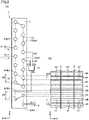
Fig. 1 is a view illustrating a refrigeration cycle apparatus according to a first embodiment; -
Fig. 2(A) is a view illustrating a heat exchanger according to the first embodiment; -
Fig. 2(B) is a view explaining the projected area of a first air passage and a second air passage of the heat exchanger illustrated inFig. 2(A) when viewed from a second direction; -
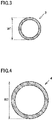
Fig. 3 is a cross-sectional view illustrating a first heat transfer tube of the heat exchanger according to the first embodiment; -
Fig. 4 is a cross-sectional view illustrating a second heat transfer tube of the heat exchanger according to the first embodiment; -
Fig. 5 is a view illustrating a heat exchanger according to a second embodiment; -
Fig. 6 is a view illustrating a heat exchanger according to a third embodiment; and -
Fig. 7 is a view illustrating a heat exchanger according to a fourth embodiment. - Hereinafter, embodiments of the present invention will be described with reference to the drawings. In the drawings, the same or corresponding portions are denoted by the same reference numerals, and the description thereof will not be repeated in principle.
- As illustrated in
Fig. 1 , arefrigeration cycle apparatus 100 according to a first embodiment includes a refrigerant circuit in which refrigerant is circulated. The refrigerant circuit includes acompressor 101, a four-way valve 102 which serves as a flow path switching unit, adecompressor 103, afirst heat exchanger 1, and asecond heat exchanger 104. Therefrigeration cycle apparatus 100 further includes afirst fan 105 configured to blow air to thefirst heat exchanger 1 and asecond fan 106 configured to blow air to thesecond heat exchanger 104. - The
compressor 101 is provided with a discharge port configured to discharge refrigerant and a suction port configured to suck refrigerant. Thedecompressor 103 may be, for example, an expansion valve. Thedecompressor 103 is connected to a first inlet/outlet 6 of thefirst heat exchanger 1. Thefirst fan 105 creates an airflow in a second direction B which will be described later. - The four-
way valve 102 is provided with a first port P1 connected to the discharge port of thecompressor 101 via a discharge pipe, a second port P2 connected to the suction port of thecompressor 101 via a suction pipe, a third opening P3 connected to a second inlet/outlet 7 and a third inlet/outlet 8 of thefirst heat exchanger 1, and a fourth opening P4 connected to thesecond heat exchanger 104. The four-way valve 102 is configured to switch between a first state in which thefirst heat exchanger 1 operates as a condenser while thesecond heat exchanger 104 operates as an evaporator, and a second state in which thesecond heat exchanger 104 operates as a condenser while thefirst heat exchanger 1 operates as an evaporator. The arrows in solid line as illustrated inFig. 1 indicate a flow direction of refrigerant circulated in the refrigerant circuit when therefrigeration cycle apparatus 100 is operating in the second state, and the arrows in dotted line as illustrated inFig. 1 indicate a flow direction of refrigerant circulated in the refrigerant circuit when therefrigeration cycle apparatus 100 is operating in the first state. - As illustrated in
Figs. 2(A) and 2(B) , thefirst heat exchanger 1 mainly includes, for example, a plurality offins 2, a plurality ofheat transfer tubes distributor 10. Thefirst heat exchanger 1 is configured to exchange heat between refrigerant flowing in each of the plurality of firstheat transfer tubes fins 2 in a second direction B. The first direction A intersects the second direction B, and may be, for example, orthogonal to the second direction B. The first direction A and the second direction B both intersect a vertical direction C, and each may be, for example, a horizontal direction. - As illustrated in
Figs. 2(A) and 2(B) , each of the plurality offins 2 extends in the vertical direction C and the second direction B, and the plurality offins 2 are spaced from each other in the first direction A. - The plurality of
heat transfer tubes heat transfer tubes 3, a plurality of secondheat transfer tubes 4, and a plurality of thirdheat transfer tubes 5. The plurality of firstheat transfer tubes 3, the plurality of secondheat transfer tubes 4, and the plurality of thirdheat transfer tubes 5 are configured to extend in the first direction A and are spaced from each other in the vertical direction C. - As illustrated in
Fig. 2(A) , the plurality of firstheat transfer tubes 3 are arranged below the plurality of secondheat transfer tubes 4 and the plurality of thirdheat transfer tubes 5. Among the plurality of heat transfer tubes provided in thefirst heat exchanger 1, at least one firstheat transfer tube 3 is arranged at the lowest position. The plurality of firstheat transfer tubes 3 are not aligned with the plurality of secondheat transfer tubes 4 in the second direction B. The plurality of thirdheat transfer tubes 5 are located above the plurality of secondheat transfer tubes 4. - As illustrated in
Fig. 2(A) , the plurality of firstheat transfer tubes 3 are connected in series to each other via afirst connection member 11. The plurality of secondheat transfer tubes 4 are connected in series to each other via asecond connection member 12. The plurality of thirdheat transfer tubes 5 are connected in series to each other via athird connection member 13. - As illustrated in
Fig. 2(A) , the plurality of firstheat transfer tubes 3 are connected in series to thedistributor 10 via a fourth connection member 21. The plurality of secondheat transfer tubes 4 are connected in series to thedistributor 10 via afifth connection member 22. The plurality of thirdheat transfer tubes 5 are connected in series to thedistributor 10 via asixth connection member 23. Each of thefirst connection member 11, thesecond connection member 12, thethird connection member 13, the fourth connection member 21, thefifth connection member 22, and thesixth connection member 23 is formed as a connection tube that connects two inlets/outlets in series to each other. InFig. 2 , eachfirst connection member 11 indicated by a solid line is connected to one end of each firstheat transfer tube 3, eachsecond connection member 12 indicated by a solid line is connected to one end of each secondheat transfer tube 4, and eachthird connection member 13 indicated by a solid line is connected to one end of each thirdheat transfer tube 5; and eachfirst connection member 11 indicated by a dotted line is connected to the other end of each firstheat transfer tube 3, eachsecond connection member 12 indicated by a dotted line is connected to the other end of each secondheat transfer tube 4, and eachthird connection member 13 indicated by a dotted line is connected to the other end of each thirdheat transfer tube 5. - As illustrated in
Fig. 2(A) , thedistributor 10 includes a first port P5 connected to the firstheat transfer tube 3 via the fourth connection member 21, a second port P6 connected to the secondheat transfer tube 4 via thefifth connection member 22, and a third port P7 connected to the thirdheat transfer tube 5 via thesixth connection member 23. The first port P5 is arranged below both the second port P6 and the third port P7. Thedistributor 10 further includes a refrigerant flow path which connects the first port P5 to the second port P6, and a refrigerant flow path which connects the first port P5 to the third port P7. - The plurality of first
heat transfer tubes 3 connected in series to each other via thefirst connection member 11 constitute a first refrigerant flow path. The plurality of secondheat transfer tubes 4 connected in series to each other via thesecond connection member 12 constitute a second refrigerant flow path. The plurality of thirdheat transfer tubes 5 connected in series to each other via thethird connection member 13 constitute a third refrigerant flow path. The first refrigerant flow path is arranged below the second refrigerant flow path. The third refrigerant flow path is located above the second refrigerant flow path, for example. - The first refrigerant flow path is connected in series to both the second refrigerant flow path and the third refrigerant flow path via the
distributor 10. The firstheat transfer tubes 3 are connected in series to both the secondheat transfer tubes 4 and the thirdheat transfer tubes 5 via thedistributor 10. The second refrigerant flow path and the third refrigerant flow path are branched from the first refrigerant flow path. The secondheat transfer tubes 4 and the thirdheat transfer tubes 5 are connected to thedistributor 10 in parallel with each other. - One end of the first refrigerant flow path is connected to the first port P5 of the
distributor 10. The other end of the first refrigerant flow path is connected to the first inlet/outlet 6. One end of the second refrigerant flow path is connected to the second port P6 of thedistributor 10. The other end of the second refrigerant flow path is connected to the second inlet/outlet 7. One end of the third refrigerant flow path is connected to the third port P7 of thedistributor 10. The other end of the third refrigerant flow path is connected to the third inlet/outlet 8. - In the first state, the refrigerant flows from the second inlet/
outlet 7 and the third inlet/outlet 8 into thefirst heat exchanger 1, after the refrigerant flows through the second refrigerant flow path and the third refrigerant flow path, the refrigerant flows through the first refrigerant flow path, and then flows out of thefirst heat exchanger 1 from the first inlet/outlet 6. In the second state, the refrigerant flows from the first inlet/outlet 6 into thefirst heat exchanger 1, after the refrigerant flows through the first refrigerant flow path, the refrigerant flows through the second refrigerant flow path and the third refrigerant flow path, and then flows out of thefirst heat exchanger 1 from the second inlet/outlet 7 and the third inlet/outlet 8. - As illustrated in
Fig. 2(A) , each of the plurality of firstheat transfer tubes 3 has the same configuration. The plurality of firstheat transfer tubes 3 include a first group of firstheat transfer tubes 3A spaced from each other in the vertical direction C, and a second group of firstheat transfer tubes 3B spaced from each other in the vertical direction C and spaced from the first group of firstheat transfer tubes 3A in the second direction B. In other words, the column number of the firstheat transfer tubes 3 arranged in the second direction B is 2 or more. In the first embodiment, the column number of the firstheat transfer tubes 3 arranged in the second direction B is equal to the column number of the secondheat transfer tubes 4 arranged in the second direction B. - The first group of first
heat transfer tubes 3A and the second group of firstheat transfer tubes 3B are adjacent to each other in the second direction B. When viewed from the second direction B, at least a part of each firstheat transfer tube 3B is located between two of the firstheat transfer tubes 3A adjacent to each other in the vertical direction. For example, the entire part of each firstheat transfer tube 3B is located between two of the firstheat transfer tubes 3A adjacent to each other in the vertical direction. The first group of firstheat transfer tubes 3A are connected in series to each other, for example. The second group of firstheat transfer tubes 3B are connected in series to each other, for example. The first group of firstheat transfer tubes 3A are connected in series to the second group of firstheat transfer tubes 3B, for example. - The lowest first
heat transfer tube 3 of the plurality of firstheat transfer tubes 3 is the lowest firstheat transfer tubes 3A in the first group of firstheat transfer tubes 3A. The lowest firstheat transfer tubes 3A in the first group of firstheat transfer tubes 3A is connected to the first inlet/outlet 6. The uppermost firstheat transfer tube 3 of the plurality of firstheat transfer tubes 3 is the uppermost firstheat transfer tube 3B in the second group of firstheat transfer tubes 3B. The uppermost firstheat transfer tube 3B in the second group of firstheat transfer tubes 3B is connected to thedistributor 10 via the fourth connection member 21. The first group of firstheat transfer tubes 3A are located on the windward side of the second group of firstheat transfer tubes 3B. - As illustrated in
Fig. 2(A) , each of the plurality of secondheat transfer tubes 4 has the same configuration. The plurality of secondheat transfer tubes 4 include a first group of secondheat transfer tubes 4A spaced from each other in the vertical direction C, and a second group of secondheat transfer tubes 4B spaced from each other in the vertical direction C and spaced from the first group of secondheat transfer tubes 4A in the second direction B. In other words, the column number of the plurality of secondheat transfer tubes 4 arranged in the second direction B is 2 or more. - The first group of second
heat transfer tubes 4A and the second group of secondheat transfer tubes 4B are adjacent to each other in the second direction B. When viewed from the second direction B, at least a part of each secondheat transfer tube 4B is located between two of the secondheat transfer tubes 4A adjacent to each other in the vertical direction. For example, the entire part of each secondheat transfer tube 4B is located between two of the secondheat transfer tubes 4A adjacent to each other in the vertical direction. The first group of secondheat transfer tubes 4A are connected in series to each other, for example. The second group of secondheat transfer tubes 4B are connected in series to each other, for example. The first group of secondheat transfer tubes 4A are connected in series to the second group of secondheat transfer tubes 4B, for example. The first group of secondheat transfer tubes 4A are located on the windward side of the second group of secondheat transfer tubes 4B. - The lowest second
heat transfer tubes 4 of the plurality of secondheat transfer tubes 4 is the lowest secondheat transfer tubes 4A in the first group of secondheat transfer tubes 4A. The lowest secondheat transfer tube 4A in the first group of secondheat transfer tubes 4A is connected to the lowest secondheat transfer tube 4B in the second group of secondheat transfer tubes 4B via thesecond connection member 12. - As illustrated in
Fig. 2(A) , each of the plurality of thirdheat transfer tubes 5 has the same configuration. The plurality of thirdheat transfer tubes 5 include a first group of thirdheat transfer tubes 5A spaced from each other in the vertical direction C, and a second group of thirdheat transfer tubes 5B spaced from each other in the vertical direction C and spaced from the first group of thirdheat transfer tubes 5A in the second direction B. In other words, the column number of the thirdheat transfer tubes 5 arranged in the second direction B is 2 or more. - The first group of third
heat transfer tubes 5A and the second group of thirdheat transfer tubes 5B are adjacent to each other in the second direction B. The first group of thirdheat transfer tubes 5A are located on the windward side of the second group of thirdheat transfer tubes 5B. When viewed from the second direction B, at least a part of each thirdheat transfer tube 5B is located between two of the thirdheat transfer tubes 5A adjacent to each other in the vertical direction. For example, the entire part of each thirdheat transfer tube 5B is located between two of the thirdheat transfer tubes 5A adjacent to each other in the vertical direction. The first group of thirdheat transfer tubes 5A are connected in series to each other, for example. The second group of thirdheat transfer tubes 5B are connected in series to each other, for example. The first group of thirdheat transfer tubes 5A are connected in series to the second group of thirdheat transfer tubes 5B, for example. - As illustrated in
Fig. 2(B) , a plurality of first air passages A1 are formed in a region adjacent to each firstheat transfer tube 3 in the vertical direction C and configured to extend in the second direction B. Each first air passage A1 is a minimum unit of the entire air passage formed in a region adjacent to each firstheat transfer tube 3 in the vertical direction C. The plurality of first air passages A1 are arranged side by side in the first direction A. Two of the first air passages A1 adjacent to each other in the first direction are partitioned by afin 2. When viewed from the second direction B, each first air passage A1 is located between the firstheat transfer tubes heat transfer tubes Fig. 2(A) ) between two of the firstheat transfer tubes 3 arranged side by side in the vertical direction C. - Among the plurality of air passages formed in a region adjacent to each of the plurality of
heat transfer tubes - As illustrated in
Fig. 2(B) , a plurality of second air passages A2 are formed in a region adjacent to each secondheat transfer tube 4 in the vertical direction C and configured to extend in the second direction B. Each second air passage A2 is a minimum unit of the entire air passage formed in a region adjacent to each secondheat transfer tube 4 in the vertical direction C. The second air passages A2 are arranged side by side in the first direction A. Two of the second air passages A2 adjacent to each other in the first direction are partitioned by afin 2. Each second air passage A2 is located above each first air passage A1. When viewed from the second direction B, each second air passage A2 is located between the secondheat transfer tubes heat transfer tubes Fig. 2(A) ) between two of the secondheat transfer tubes 4 arranged side by side in the vertical direction C. - As illustrated in
Fig. 2(B) , when viewed from the second direction B, the projected area of each first air passage A1 is greater than the projected area of each second air passage A2. In other words, the width of each first air passage A1 in the vertical direction C is greater than the width of each second air passage A2 in the vertical direction C. - As illustrated in
Fig. 2(A) , the gap D1 between two of the firstheat transfer tubes 3 arranged side by side in the vertical direction C is equal to the gap D2 between two of the secondheat transfer tubes 4 arranged side by side in the vertical direction C. As illustrated inFigs. 2(A) ,3 and 4 , a width W1 of each firstheat transfer tube 3 in the vertical direction is smaller than a width W2 of each secondheat transfer tube 4 in the vertical direction. Therefore, the gap D3 between the firstheat transfer tubes heat transfer tubes heat transfer tubes heat transfer tubes - The projected area of each first air passage A1 is obtained by subtracting, from the projected area of a space between two of the first
heat transfer tubes 3 located on the most windward side and arranged adjacent to each other in the vertical direction C, the projected area of a firstheat transfer tube 3 located between the two firstheat transfer tubes 3. The projected area of each second air passage A2 is obtained by subtracting, from the projected area of a space between two of the secondheat transfer tubes 4 located on the most windward side and arranged adjacent to each other in the vertical direction C, the projected area of a secondheat transfer tube 4 located between the two secondheat transfer tubes 4. - As illustrated in
Figs. 3 and 4 , the flow path cross-sectional area of the refrigerant in each of the plurality of firstheat transfer tubes 3 is smaller than the flow path cross-sectional area of the refrigerant in each of the plurality of secondheat transfer tubes 4. - As illustrated in
Figs. 2(A) ,3 and 4 , each of the plurality of firstheat transfer tubes 3 and the plurality of secondheat transfer tubes 4 is formed as a circular tube, for example. As illustrated inFigs. 2(A) ,3 and 4 , the outer diameter W1 of each of the plurality of firstheat transfer tubes 3 is smaller than the outer diameter W2 of each of the plurality of secondheat transfer tubes 4. The inner diameter of each of the plurality of firstheat transfer tubes 3 is smaller than the inner diameter of each of the plurality of secondheat transfer tubes 4. - A plurality of third air passages (not shown) are formed in a region adjacent to each third
heat transfer tube 5 in the vertical direction C and configured to extend in the second direction B. The third air passages are arranged side by side in the first direction A. Two of the third air passages adjacent to each other in the first direction are partitioned by afin 2. Each third air passage is a minimum unit of the entire air passage formed in a region adjacent to each thirdheat transfer tube 5 in the vertical direction C. When viewed from the second direction B, each third air passage is located between the thirdheat transfer tubes heat transfer tubes heat transfer tubes 5 arranged side by side in the vertical direction C. - When viewed from the second direction B, the projected area of each first air passage A1 is greater than the projected area of each third air passage. The gap between two of the plurality of first
heat transfer tubes 3 adjacent to each other in the vertical direction is equal to the gap between two of the plurality of thirdheat transfer tubes 5 adjacent to each other in the vertical direction. The vertical width W1 of each firstheat transfer tube 3 in the vertical direction is smaller than the vertical width of each thirdheat transfer tube 5 in the vertical direction. The flow path cross-sectional area of the refrigerant in each of the plurality of firstheat transfer tubes 3 is smaller than the flow path cross-sectional area of the refrigerant in each of the plurality of thirdheat transfer tubes 5. - The projected area of each third air passage is equal to the projected area of each second air passage. The gap between two of the plurality of third
heat transfer tubes 5 adjacent to each other in the vertical direction is equal to the gap between two of the plurality of secondheat transfer tubes 4 adjacent to each other in the vertical direction. The width of each thirdheat transfer tube 5 in the vertical direction is equal to the width W2 of each secondheat transfer tube 4 in the vertical direction. The flow path cross-sectional area of the refrigerant in each of the plurality of thirdheat transfer tubes 5 is equal to the flow path cross-sectional area of the refrigerant in each of the plurality of secondheat transfer tubes 4. - In the
first heat exchanger 1, the flow path cross-sectional area of the refrigerant in the firstheat transfer tube 3 is smaller than the flow path cross-sectional area of the refrigerant in the secondheat transfer tube 4. In other words, the pressure loss of the refrigerant flowing in the firstheat transfer tube 3 is greater than the pressure loss of the refrigerant flowing in the secondheat transfer tube 4. Therefore, when the refrigerant flows from the firstheat transfer tube 3 into the secondheat transfer tube 4 in the second state, the pressure of the refrigerant flowing in the firstheat transfer tube 3 is higher than the pressure of the refrigerant flowing in the secondheat transfer tube 4. In the second state, the refrigerant flowing through the firstheat transfer tube 3 and the secondheat transfer tube 4 is in a gas-liquid two-phase state, and the pressure of the refrigerant is positively correlated to the temperature of the refrigerant. Therefore, in the second state, the temperature of the refrigerant flowing in the firstheat transfer tube 3 is higher than the temperature of the refrigerant flowing in the secondheat transfer tube 4. - Further, in the
first heat exchanger 1, when viewed from the second direction B, the projected area of the first air passage A1 is greater than the projected area of the second air passage A2. Therefore, the air volume in the first air passage A1 is greater than the air volume in the second air passage A2, which makes it easier to drain the condensation water in the first air passage A1 to the outside. - Specifically, in the
first heat exchanger 1, the air flowing around the firstheat transfer tube 3 and the refrigerant flowing in the firstheat transfer tube 3 prevent frost from being formed on the firstheat transfer tube 3. Therefore, even if the temperature difference between the temperature of the refrigerant flowing in the firstheat transfer tube 3 and the temperature of the refrigerant flowing in the secondheat transfer tube 4 is smaller than the temperature difference between the temperature of the overcooling heat exchange member and the temperature of the other heat exchange members in the conventional heat exchanger mentioned above, it is possible to prevent frost from being formed on the firstheat transfer tube 3 at a capacity equal to or greater than that of the conventional heat exchanger mentioned above. In other words, according to thefirst heat exchanger 1, it is possible to prevent the formation of frost while preventing the performance thereof from being deteriorated by the frost as compared with a conventional outdoor heat exchanger. - Further, in the
first heat exchanger 1, an air passage which is located at the lowest position among the plurality of air passages formed in a region adjacent to each of the plurality ofheat transfer tubes first heat exchanger 1 in which the first air passage A1 is constituted by the lowest air passage, it is possible to effectively prevent the performance thereof from being deteriorated by the frost. - Moreover, the
first heat exchanger 1 further includes a plurality of thirdheat transfer tubes 5 connected to the plurality of firstheat transfer tubes 3 in parallel with the plurality of secondheat transfer tubes 4. Therefore, the flow rate of the refrigerant flowing through each of the firstheat transfer tubes 3 is greater than the flow rate of the refrigerant flowing through each of the secondheat transfer tubes 4, which makes the flow velocity of the refrigerant flowing through each of the firstheat transfer tubes 3 faster than the flow velocity of the refrigerant flowing through each of the secondheat transfer tubes 4. As a result, the pressure loss of the refrigerant flowing through the firstheat transfer tube 3 becomes greater than the pressure loss of the refrigerant flowing through the secondheat transfer tube 4 due to the difference in the flow path cross-sectional area and the difference in the flow velocity, whereby the temperature of the refrigerant flowing through the firstheat transfer tube 3 becomes higher than the temperature of the refrigerant flowing through the secondheat transfer tube 4 in the second state. - In the
refrigeration cycle apparatus 100, thefirst heat exchanger 1 is configured in such a manner that the refrigerant flows from the firstheat transfer tube 3 into the secondheat transfer tube 4 in the second state. Thus, it is possible for thefirst heat exchanger 1 to prevent the formation of frost while preventing the performance thereof from being deteriorated by the frost as compared with a conventional outdoor heat exchanger. As a result, the operation efficiency of therefrigeration cycle apparatus 100 in the second state is improved than that of a refrigeration cycle apparatus equipped with the conventional outdoor heat exchanger. - As illustrated in
Fig. 5 , afirst heat exchanger 1A according to a second embodiment has basically the same configuration as thefirst heat exchanger 1 according to the first embodiment, but differs from thefirst heat exchanger 1 according to the first embodiment in that the gap D1 between two of the firstheat transfer tubes 3 adjacent to each other in the vertical direction C is greater than the gap D2 between two of the secondheat transfer tubes 4 adjacent to each other in the vertical direction C. - In this case, the projected area of the first air passage A1 in the
first heat exchanger 1A is greater than the projected area of the second air passage A2 in thefirst heat exchanger 1A. Further, when thefirst heat exchanger 1A having the gap D2 is compared with thefirst heat exchanger 1 having the same gap D2 according to the first embodiment, the gap D1 in thefirst heat exchanger 1A is greater than the gap D1 in thefirst heat exchanger 1, whereby the projected area of the first air passage A1 in thefirst heat exchanger 1A is greater than the projected area of the first air passage A1 in thefirst heat exchanger 1. As a result, it is possible for thefirst heat exchanger 1A according to the second embodiment to further prevent frost from being formed on the firstheat transfer tube 3 as compared with thefirst heat exchanger 1 according to the first embodiment. - As illustrated in
Fig. 6 , afirst heat exchanger 1B according to a third embodiment has basically the same configuration as thefirst heat exchanger 1 according to the first embodiment, but differs from thefirst heat exchanger 1 according to the first embodiment in that the column number of the plurality of firstheat transfer tubes 3 arranged in the second direction B is smaller than the column number of the plurality of secondheat transfer tubes 4 arranged in the second direction B. - The column number of the first
heat transfer tubes 3 arranged in the second direction B is 1 or more. The column number of the plurality of secondheat transfer tubes 4 arranged in the second direction B is greater than the column number of the plurality of firstheat transfer tubes 3 arranged in the second direction B, and is 2 or more. - With reference to
Fig. 6 , a configuration example in which the column number of the firstheat transfer tubes 3 arranged in the second direction B is 1 will be described. In this configuration, each first air passage A1 is located between two adjacent firstheat transfer tubes 3 arranged side by side in the vertical direction C. Therefore, the width of the first air passage A1 in the vertical direction C is equal to the gap D1 between the two adjacent firstheat transfer tubes 3 arranged side by side in the vertical direction C. - On the other hand, each second air passage A2 is located between the second
heat transfer tubes heat transfer tubes Fig. 2(A) ) between two of the secondheat transfer tubes 4 arranged side by side in the vertical direction C. - Thus, even when the gap D1 is equal to the gap D2, the width of the first air passage A1 in the vertical direction C is twice as great as the width of the second air passage A2 in the vertical direction C. As a result, the projected area of the first air passage A1 is twice as great as the projected area of the second air passage A2, whereby the drainage efficiency of the first air passage A1 is considerably higher than the drainage efficiency of the second air passage A2.
- When the
first heat exchanger 1B according to the third embodiment is compared with thefirst heat exchanger 1 according to the first embodiment in which the gap D1 and the gap D2 are equal to those in thefirst heat exchanger 1B, the projected area of the first air passage A1 in thefirst heat exchanger 1B is greater than the projected area of the first air passage A1 in thefirst heat exchanger 1. Thus, the drainage efficiency of the first air passage A1 in thefirst heat exchanger 1B becomes higher than the drainage efficiency of the first air passage A1 in thefirst heat exchanger 1. - Moreover, in the
first heat exchanger 1 according to the third embodiment, the column number of the firstheat transfer tubes 3 arranged in the second direction B may be two or more as long as the column number of the firstheat transfer tubes 3 arranged in the second direction B is smaller than the column number of the firstheat transfer tubes 3 arranged in the second direction B. Even in this case, the column number of the firstheat transfer tubes 3 which are located on the most windward side and arranged between two of the firstheat transfer tubes 3 adjacent to each other in the vertical direction C when viewed from the second direction B is smaller than the column number of the secondheat transfer tubes 4 which are located on the most windward side and arranged between two of the secondheat transfer tubes 4 adjacent to each other in the vertical direction C. - As described above, the projected area of each first air passage A1 is obtained by subtracting, from the projected area of a space between the projected area of two of the first
heat transfer tubes 3 located on the most windward side and arranged adjacent to each other in the vertical direction C, the projected area of a firstheat transfer tube 3 arranged between the two firstheat transfer tubes 3. The projected area of each second air passage A2 is obtained by subtracting, from the projected area of a space between two of the secondheat transfer tubes 4 located on the most windward side and arranged adjacent to each other in the vertical direction C, the projected area of a secondheat transfer tube 4 arranged between the two secondheat transfer tubes 4. - In the
first heat exchanger 1B, even if the column number of the firstheat transfer tubes 3 is two or more, since the column number of the firstheat transfer tubes 3 is smaller than the column number of the secondheat transfer tubes 4, the number of the firstheat transfer tubes 3 arranged between two of the firstheat transfer tubes 3 is smaller than the number of the secondheat transfer tubes 4 arranged between two of the secondheat transfer tubes 4. As a result, the projected area of the first air passage A1 is greater than the projected area of the second air passage A2, and thereby, the drainage efficiency of the first air passage A1 is higher than the drainage efficiency of the second air passage A2. - As illustrated in
Fig. 7 , thefirst heat exchanger 1C according to a fourth embodiment has basically the same configuration as thefirst heat exchanger 1A according to the second embodiment, but differs from thefirst heat exchanger 1A according to the second embodiment in that the column number of the plurality of firstheat transfer tubes 3 arranged in the second direction B is smaller than the column number of the plurality of secondheat transfer tubes 4 arranged in the second direction B. From another point of view, thefirst heat exchanger 1C has basically the same configuration as thefirst heat exchanger 1B according to the third embodiment, but differs from thefirst heat exchanger 1B according to the third embodiment in that the gap D1 between two of the firstheat transfer tubes 3 adjacent to each other in the vertical direction C is greater than the gap D2 between two of the secondheat transfer tubes 4 adjacent to each other in the vertical direction C. - Since the
first heat exchanger 1C includes both the configuration of thefirst heat exchanger 1A and the configuration of thefirst heat exchanger 1B, the projected area of the first air passage A1 of thefirst heat exchanger 1C is greater than the projected area of the second air passage A2 of thefirst heat exchanger 1C, and is greater than the projected area of the first air passage A1 of thefirst heat exchanger 1, the projected area of the first air passage A1 of thefirst heat exchanger 1A, and the projected area of the first air passage A1 of thefirst heat exchanger 1B. As a result, it is possible for thefirst heat exchanger 1C to more efficiently prevent frost from being formed on the firstheat transfer tube 3 than thefirst heat exchanger 1, thefirst heat exchanger 1A, and thefirst heat exchanger 1B. - In the
first heat exchangers heat transfer tubes heat transfer tubes - Each of the
first heat exchangers heat transfer tubes 3 and a plurality of secondheat transfer tubes 4, but it is not limited thereto. Each of thefirst heat exchangers heat transfer tube 3 and one secondheat transfer tube 4. - Although the embodiments of the present invention have been described above, the embodiments described above may be modified in various ways. The scope of the present invention is not limited to the embodiments described above. The scope of the present invention is defined by the terms of the claims, and is intended to include all modifications within the meaning and scope equivalent to the terms of the claims.
- 1, 1A, 1B, 1C: first heat exchanger; 2: fin; 3, 3A, 3B: first heat transfer tube; 4, 4A, 4B: second heat transfer tube; 5, 5A, 5B: third heat transfer tube; 6: first inlet/outlet; 7: second inlet/outlet; 8: third inlet/outlet; 10: distributor; 11: first connection member; 12: second connection member; 13: third connection member; 21: fourth connection member; 22: fifth connection member; 23: sixth connection member; 100: refrigeration cycle apparatus; 101: compressor; 102: four-way valve; 103: decompressor; 104: second heat exchanger; 105: first fan; 106: second fan
Claims (7)
- A heat exchanger comprising:a plurality of heat transfer tubes;the plurality of heat transfer tubes including:at least one first heat transfer tube configured to extend in a first direction intersecting a vertical direction; andat least one second heat transfer tube located above the at least one first heat transfer tube and configured to extend in the first direction,a first air passage being formed in a region adjacent to the at least one first heat transfer tube in the vertical direction and being configured to extend in a second direction intersecting both the vertical direction and the first direction,a second air passage being formed in a region adjacent to the at least one second heat transfer tube in the vertical direction and being configured to extend in the second direction,the at least one first heat transfer tube being connected in series to the at least one second heat transfer tube,a flow path cross-sectional area of the at least one first heat transfer tube being smaller than a flow path cross-sectional area of the at least one second heat transfer tube, andwhen viewed from the second direction, a projected area of the first air passage being greater than a projected area of the second air passage.
- The heat exchanger according to claim 1, whereinthe at least one first heat transfer tube includes a plurality of the first heat transfer tubes,the at least one second heat transfer tube includes a plurality of the second heat transfer tubes,the plurality of first heat transfer tubes are spaced from each other in the vertical direction and connected in series to each other,the plurality of second heat transfer tubes are spaced from each other in the vertical direction and connected in series to each other,the first air passage is located between two of the plurality of first heat transfer tubes adjacent to each other in the vertical direction, andthe second air passage is located between two of the plurality of second heat transfer tubes adjacent to each other in the vertical direction.
- The heat exchanger according to claim 2, wherein
a gap between two of the plurality of first heat transfer tubes adjacent to each other in the vertical direction is greater than a gap between two of the plurality of second heat transfer tubes adjacent to each other in the vertical direction. - The heat exchanger according to claim 2 or 3, wherein
the column number of the plurality of first heat transfer tubes arranged in the second direction is smaller than the column number of the plurality of second heat transfer tubes arranged in the second direction. - The heat exchanger according to any one of claims 2 to 4 further comprising:
a plurality of third heat transfer tubes connected to the plurality of first heat transfer tubes in parallel with the plurality of second heat transfer tubes. - The heat exchanger according to any one of claims 1 to 5, wherein among a plurality of air passages, each of which is formed in a region adjacent to each of the plurality of heat transfer tubes in the vertical direction and is configured to extend in the second direction, an air passage located at the lowest position constitutes the first air passage.
- A refrigeration cycle apparatus comprising:a compressor;a flow path switching unit;a decompressor;a first heat exchanger; anda second heat exchanger,the flow path switching unit being configured to switch between a first state and a second state, in the first state, refrigerant flowing through the compressor, the first heat exchanger, the decompressor, and the second heat exchanger in this order, and in the second state, the refrigerant flowing through the compressor, the second heat exchanger, the decompressor, and the first heat exchanger in this order,the first heat exchanger being the heat exchanger according to any one of claims 1 to 6,the refrigerant flowing from the at least one second heat transfer tube to the at least one first heat transfer tube in the first state, and flowing from the at least one first heat transfer tube to the at least one second heat transfer tube in the second state.
Applications Claiming Priority (1)
| Application Number | Priority Date | Filing Date | Title |
|---|---|---|---|
| PCT/JP2019/029678 WO2021019647A1 (en) | 2019-07-29 | 2019-07-29 | Heat exchanger and refrigeration cycle device |
Publications (2)
| Publication Number | Publication Date |
|---|---|
| EP4006474A1 true EP4006474A1 (en) | 2022-06-01 |
| EP4006474A4 EP4006474A4 (en) | 2022-08-03 |
Family
ID=74230320
Family Applications (1)
| Application Number | Title | Priority Date | Filing Date |
|---|---|---|---|
| EP19940038.3A Withdrawn EP4006474A4 (en) | 2019-07-29 | 2019-07-29 | HEAT EXCHANGER AND REFRIGERATION CYCLE DEVICE |
Country Status (3)
| Country | Link |
|---|---|
| EP (1) | EP4006474A4 (en) |
| JP (1) | JP7258151B2 (en) |
| WO (1) | WO2021019647A1 (en) |
Family Cites Families (6)
| Publication number | Priority date | Publication date | Assignee | Title |
|---|---|---|---|---|
| JPS618775U (en) * | 1984-06-15 | 1986-01-20 | 三菱電機株式会社 | Cross finch tube heat exchanger |
| JPH06272903A (en) * | 1993-03-23 | 1994-09-27 | Mitsubishi Heavy Ind Ltd | Outdoor device of air conditioner |
| JP2004347135A (en) | 2003-04-30 | 2004-12-09 | Toshiba Kyaria Kk | Air conditioner outdoor unit |
| CN201081461Y (en) * | 2007-07-16 | 2008-07-02 | 四川长虹电器股份有限公司 | Tubular plate type heat exchanger |
| JP6045695B2 (en) | 2013-06-13 | 2016-12-14 | 三菱電機株式会社 | Air conditioner |
| CN206787114U (en) * | 2017-05-08 | 2017-12-22 | 广东美的暖通设备有限公司 | Heat exchanger assembly and air conditioner |
-
2019
- 2019-07-29 JP JP2021536488A patent/JP7258151B2/en active Active
- 2019-07-29 EP EP19940038.3A patent/EP4006474A4/en not_active Withdrawn
- 2019-07-29 WO PCT/JP2019/029678 patent/WO2021019647A1/en not_active Ceased
Also Published As
| Publication number | Publication date |
|---|---|
| WO2021019647A1 (en) | 2021-02-04 |
| JPWO2021019647A1 (en) | 2021-02-04 |
| JP7258151B2 (en) | 2023-04-14 |
| EP4006474A4 (en) | 2022-08-03 |
Similar Documents
| Publication | Publication Date | Title |
|---|---|---|
| EP3805651B1 (en) | Air conditioner outdoor unit and air conditioner | |
| EP3156752B1 (en) | Heat exchanger | |
| JP6576577B1 (en) | Refrigerant distributor, heat exchanger, and air conditioner | |
| CN110398163B (en) | heat exchanger | |
| WO2021234958A1 (en) | Heat exchanger, outdoor unit equipped with heat exchanger, and air conditioner equipped with outdoor unit | |
| US20110120177A1 (en) | Heat exchanger for shedding water | |
| JPWO2018225252A1 (en) | Heat exchanger and refrigeration cycle device | |
| US11384996B2 (en) | Heat exchanger and refrigeration cycle apparatus | |
| WO2017208493A1 (en) | Air conditioner | |
| US11802719B2 (en) | Refrigeration cycle apparatus | |
| CN111902683A (en) | Heat exchanger and refrigeration cycle device | |
| US11898781B2 (en) | Gas header, heat exchanger, and refrigeration cycle apparatus | |
| EP4006474A1 (en) | Heat exchanger and refrigeration cycle device | |
| WO2019026242A1 (en) | Heat exchanger, and refrigeration cycle device | |
| EP3734190A1 (en) | Heat exchanger and refrigeration cycle device | |
| JP7357785B2 (en) | Heat exchanger, outdoor unit equipped with heat exchanger, and air conditioner equipped with outdoor unit | |
| US20240410602A1 (en) | Heat exchanger and air-conditioning apparatus | |
| JP7080395B2 (en) | Heat exchanger unit and refrigeration cycle device | |
| US11460228B2 (en) | Heat exchanger, outdoor unit and refrigeration cycle apparatus | |
| CN117355721A (en) | Heat exchanger, outdoor unit of air-conditioning device provided with heat exchanger, and air-conditioning device provided with outdoor unit of air-conditioning device | |
| JP6537868B2 (en) | Heat exchanger | |
| JP7566155B2 (en) | Heat exchanger and air conditioning device | |
| CN110945300B (en) | Refrigerant distributor, heat exchanger, and refrigeration cycle device |
Legal Events
| Date | Code | Title | Description |
|---|---|---|---|
| STAA | Information on the status of an ep patent application or granted ep patent |
Free format text: STATUS: THE INTERNATIONAL PUBLICATION HAS BEEN MADE |
|
| PUAI | Public reference made under article 153(3) epc to a published international application that has entered the european phase |
Free format text: ORIGINAL CODE: 0009012 |
|
| STAA | Information on the status of an ep patent application or granted ep patent |
Free format text: STATUS: REQUEST FOR EXAMINATION WAS MADE |
|
| 17P | Request for examination filed |
Effective date: 20220112 |
|
| AK | Designated contracting states |
Kind code of ref document: A1 Designated state(s): AL AT BE BG CH CY CZ DE DK EE ES FI FR GB GR HR HU IE IS IT LI LT LU LV MC MK MT NL NO PL PT RO RS SE SI SK SM TR |
|
| A4 | Supplementary search report drawn up and despatched |
Effective date: 20220701 |
|
| RIC1 | Information provided on ipc code assigned before grant |
Ipc: F28D 1/053 20060101AFI20220627BHEP |
|
| DAV | Request for validation of the european patent (deleted) | ||
| DAX | Request for extension of the european patent (deleted) | ||
| STAA | Information on the status of an ep patent application or granted ep patent |
Free format text: STATUS: EXAMINATION IS IN PROGRESS |
|
| 17Q | First examination report despatched |
Effective date: 20231116 |
|
| GRAP | Despatch of communication of intention to grant a patent |
Free format text: ORIGINAL CODE: EPIDOSNIGR1 |
|
| STAA | Information on the status of an ep patent application or granted ep patent |
Free format text: STATUS: GRANT OF PATENT IS INTENDED |
|
| INTG | Intention to grant announced |
Effective date: 20240703 |
|
| STAA | Information on the status of an ep patent application or granted ep patent |
Free format text: STATUS: THE APPLICATION IS DEEMED TO BE WITHDRAWN |
|
| 18D | Application deemed to be withdrawn |
Effective date: 20241105 |