EP4006424A1 - Heating cooker - Google Patents
Heating cooker Download PDFInfo
- Publication number
- EP4006424A1 EP4006424A1 EP20846465.1A EP20846465A EP4006424A1 EP 4006424 A1 EP4006424 A1 EP 4006424A1 EP 20846465 A EP20846465 A EP 20846465A EP 4006424 A1 EP4006424 A1 EP 4006424A1
- Authority
- EP
- European Patent Office
- Prior art keywords
- heating cooking
- pull
- cooking apparatus
- cooking chamber
- heated
- Prior art date
- Legal status (The legal status is an assumption and is not a legal conclusion. Google has not performed a legal analysis and makes no representation as to the accuracy of the status listed.)
- Pending
Links
Images


Classifications
-
- H—ELECTRICITY
- H05—ELECTRIC TECHNIQUES NOT OTHERWISE PROVIDED FOR
- H05B—ELECTRIC HEATING; ELECTRIC LIGHT SOURCES NOT OTHERWISE PROVIDED FOR; CIRCUIT ARRANGEMENTS FOR ELECTRIC LIGHT SOURCES, IN GENERAL
- H05B6/00—Heating by electric, magnetic or electromagnetic fields
- H05B6/64—Heating using microwaves
-
- F—MECHANICAL ENGINEERING; LIGHTING; HEATING; WEAPONS; BLASTING
- F24—HEATING; RANGES; VENTILATING
- F24C—DOMESTIC STOVES OR RANGES ; DETAILS OF DOMESTIC STOVES OR RANGES, OF GENERAL APPLICATION
- F24C7/00—Stoves or ranges heated by electric energy
- F24C7/02—Stoves or ranges heated by electric energy using microwaves
-
- F—MECHANICAL ENGINEERING; LIGHTING; HEATING; WEAPONS; BLASTING
- F24—HEATING; RANGES; VENTILATING
- F24C—DOMESTIC STOVES OR RANGES ; DETAILS OF DOMESTIC STOVES OR RANGES, OF GENERAL APPLICATION
- F24C15/00—Details
- F24C15/02—Doors specially adapted for stoves or ranges
-
- F—MECHANICAL ENGINEERING; LIGHTING; HEATING; WEAPONS; BLASTING
- F24—HEATING; RANGES; VENTILATING
- F24C—DOMESTIC STOVES OR RANGES ; DETAILS OF DOMESTIC STOVES OR RANGES, OF GENERAL APPLICATION
- F24C15/00—Details
- F24C15/16—Shelves, racks or trays inside ovens; Supports therefor
-
- F—MECHANICAL ENGINEERING; LIGHTING; HEATING; WEAPONS; BLASTING
- F24—HEATING; RANGES; VENTILATING
- F24C—DOMESTIC STOVES OR RANGES ; DETAILS OF DOMESTIC STOVES OR RANGES, OF GENERAL APPLICATION
- F24C15/00—Details
- F24C15/16—Shelves, racks or trays inside ovens; Supports therefor
- F24C15/162—Co-operating with a door, e.g. operated by the door
-
- H—ELECTRICITY
- H05—ELECTRIC TECHNIQUES NOT OTHERWISE PROVIDED FOR
- H05B—ELECTRIC HEATING; ELECTRIC LIGHT SOURCES NOT OTHERWISE PROVIDED FOR; CIRCUIT ARRANGEMENTS FOR ELECTRIC LIGHT SOURCES, IN GENERAL
- H05B6/00—Heating by electric, magnetic or electromagnetic fields
- H05B6/64—Heating using microwaves
- H05B6/6402—Aspects relating to the microwave cavity
-
- H—ELECTRICITY
- H05—ELECTRIC TECHNIQUES NOT OTHERWISE PROVIDED FOR
- H05B—ELECTRIC HEATING; ELECTRIC LIGHT SOURCES NOT OTHERWISE PROVIDED FOR; CIRCUIT ARRANGEMENTS FOR ELECTRIC LIGHT SOURCES, IN GENERAL
- H05B6/00—Heating by electric, magnetic or electromagnetic fields
- H05B6/64—Heating using microwaves
- H05B6/6414—Aspects relating to the door of the microwave heating apparatus
-
- H—ELECTRICITY
- H05—ELECTRIC TECHNIQUES NOT OTHERWISE PROVIDED FOR
- H05B—ELECTRIC HEATING; ELECTRIC LIGHT SOURCES NOT OTHERWISE PROVIDED FOR; CIRCUIT ARRANGEMENTS FOR ELECTRIC LIGHT SOURCES, IN GENERAL
- H05B6/00—Heating by electric, magnetic or electromagnetic fields
- H05B6/64—Heating using microwaves
- H05B6/6426—Aspects relating to the exterior of the microwave heating apparatus, e.g. metal casing, power cord
-
- H—ELECTRICITY
- H05—ELECTRIC TECHNIQUES NOT OTHERWISE PROVIDED FOR
- H05B—ELECTRIC HEATING; ELECTRIC LIGHT SOURCES NOT OTHERWISE PROVIDED FOR; CIRCUIT ARRANGEMENTS FOR ELECTRIC LIGHT SOURCES, IN GENERAL
- H05B6/00—Heating by electric, magnetic or electromagnetic fields
- H05B6/64—Heating using microwaves
- H05B6/72—Radiators or antennas
- H05B6/725—Rotatable antennas
Definitions
- the present invention relates to a heating cooking apparatus.
- PTL 1 discloses a pull-out heating cooking apparatus.
- the pull-out heating cooking apparatus disclosed in PTL 1 includes a heating cooking apparatus main body and a pull-out body.
- the heating cooking apparatus main body includes a heating cooking chamber.
- the pull-out body can be drawn toward the outside of the heating cooking apparatus main body from a state where the pull-out body is accommodated in the heating cooking chamber.
- Heating functions of the pull-out heating cooking apparatus disclosed in PTL 1 include a microwave heating function and a rapid hot air heating function.
- the microwave heating function is a function of applying microwaves toward an object to be heated.
- a microwave radiation port is formed in a side wall of the heating cooking chamber.
- an object of the present invention is to provide a heating cooking apparatus that can efficiently irradiate an object to be heated with microwaves.
- a heating cooking apparatus of the present invention includes a heating cooking chamber and a microwave supply unit. An object to be heated is accommodated in the heating cooking chamber.
- the microwave supply unit includes a radiation port and supplies microwaves to the heating cooking chamber through the radiation port. The radiation port is positioned below the heating cooking chamber.
- an object to be heated can be efficiently irradiated with microwaves.
- FIG. 1 is a perspective view illustrating an appearance of the pull-out heating cooking apparatus 100 according to the present embodiment.
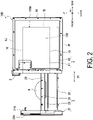
- FIG. 2 is a right side view illustrating the pull-out heating cooking apparatus 100 according to the present embodiment.
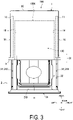
- FIG. 3 is a top view illustrating the pull-out heating cooking apparatus 100 according to the present embodiment. More specifically, FIG. 1 to FIG. 3 illustrate the pull-out heating cooking apparatus 100 in a state where a pull-out body 2 is pulled out. Further, FIG. 1 illustrates the appearance of the pull-out heating cooking apparatus 100 when viewed from above obliquely from the right.
- the pull-out heating cooking apparatus 100 is one example of a heating cooking apparatus.
- the pull-out heating cooking apparatus 100 heats and cooks an object H to be heated.
- the object H to be heated is, for example, a food product.
- the pull-out heating cooking apparatus 100 includes a heating chamber 1, the pull-out body 2, an operation panel 3, a control unit 5, and a storage unit 6.
- a side on which the operation panel 3 of the pull-out heating cooking apparatus 100 is disposed is defined as a front side of the pull-out heating cooking apparatus 100, and a side opposite to the front side is defined as a rear side of the pull-out heating cooking apparatus 100.
- a right side of the pull-out heating cooking apparatus 100 when the pull-out heating cooking apparatus 100 is viewed from the front side is defined as a right side, and a side opposite to the right side is defined as a left side of the pull-out heating cooking apparatus 100.
- a side on which the operation panel 3 is disposed is defined as an upper side of the pull-out heating cooking apparatus 100, and a side opposite to the upper side is defined as a lower side of the pull-out heating cooking apparatus 100. Note that these orientations do not limit the orientation of the pull-out heating cooking apparatus according to the present invention when in use.
- the heating chamber 1 is a box-like member. Specifically, the heating chamber 1 includes a right outer wall 1G, a left outer wall 1H, a top outer wall 1J, a bottom outer wall 1F, and a back outer wall 1K. The heating chamber 1 also includes a heating cooking chamber 100A therein.
- the heating cooking chamber 100A includes an accommodation space 120 that accommodates the object H to be heated.
- the accommodation space 120 is a space that can accommodate the object to be heated H and has a predetermined volume.
- the heating cooking chamber 100A includes a right wall 1A, a left wall 1B, a top wall 1C, a bottom wall 1D, and a back wall 1E.
- the shape of the heating cooking chamber 100A is, for example, a substantially rectangular parallelepiped shape. Materials of the right wall 1A, the left wall 1B, the top wall 1C, the bottom wall 1D, and the back wall 1E are, for example, a metal.
- the front side of the heating cooking chamber 100A is opened for allowing the object to be heated H to be inserted and removed.
- the heating chamber 1 further includes a space between the bottom wall 1D and the bottom outer wall 1F.
- the heating chamber 1 further includes a space between the right wall 1A and the right outer wall 1G.
- the heating chamber 1 further includes a space between the left wall 1B and the left outer wall 1H.
- the heating chamber 1 further includes a space between the top wall 1C and the top outer wall 1J.
- the heating chamber 1 further includes a space between the back wall 1E and the back outer wall 1K.
- the operation panel 3 includes an operation unit and a display portion.
- the operation unit receives an operation from a user.
- the operation unit includes various types of keys.
- the display portion displays various pieces of information.
- the display portion includes a liquid crystal panel.
- the operation panel 3 is located on an upper portion of a front face of the heating chamber 1.
- the storage unit 6 includes a random access memory (RAM) and a read only memory (ROM).
- the storage unit 6 stores control programs used for controlling operations of each part of the pull-out heating cooking apparatus 100.
- the storage unit 6 stores setting information input when the operation panel 3 is operated.
- the control unit 5 is a hardware circuit that includes a processor such as a central processing unit (CPU).
- the control unit 5 executes a control program stored in the storage unit 6.
- FIG. 4 is a perspective view of the pull-out body 2 and the placing portion 22 according to the present embodiment.
- the pull-out heating cooking apparatus 100 further includes the placing portion 22.
- the pull-out body 2 is freely pulled out from the heating cooking chamber 100A along a predetermined direction D1.
- the predetermined direction D1 is a direction along a front-rear direction. More specifically, the pull-out body 2 can be pulled out and pulled in with respect to the heating chamber 1.
- the pull-out body 2 includes a pull-out main body 20.
- the pull-out main body 20 includes a door portion 21 and a support portion 23.
- the object H to be heated can be placed on the placing portion 22.
- the placing portion 22 is, for example, a plate-like member made of a ceramic, glass, or a synthetic resin, and is preferably a plate-like member made of a ceramic or glass. As a result, the placing portion 22 transmits microwaves. In addition, the placing portion 22 is transparent or translucent. The term "translucent" includes color transparency.
- the door portion 21 can open and close an opening on the front side of the heating cooking chamber 100A.
- the door portion 21 is a substantially rectangular plate-like member.
- the door portion 21 includes a front face 21A and a rear face 21B.
- the door portion 21 opens the opening on the front side of the heating cooking chamber 100A in a state where the pull-out body 2 is pulled out of the heating cooking chamber 100A.
- the door portion 21 closes the opening on the front side of the heating cooking chamber 100A in a state where the pull-out body 2 is pulled into the heating cooking chamber 100A. Meanwhile, in a state where the pull-out body 2 is pushed into the heating cooking chamber 100A, a distance between the top wall 1C and the bottom wall 1D is shorter than a distance between the back wall 1E and the rear face 21B.
- the support portion 23 is fixed to the rear face 21B of the door portion 21, and supports a peripheral portion of the placing portion 22 such that the placing portion 22 is held in a horizontal state.
- the support portion 23 includes a base plate portion 23A, a back plate portion 23B, a right plate portion 23C, a left plate portion 23D, and a pair of rollers 23E.
- the base plate portion 23A includes a rectangular opening 23A1.
- the rectangular opening 23A1 is positioned at a substantially center portion of the base plate portion 23A.
- the back plate portion 23B, the right plate portion 23C, and the left plate portion 23D are erected upward from a peripheral portion of the base plate portion 23A.
- the placing portion 22 is fitted between the door portion 21, the back plate portion 23B, the right plate portion 23C, and the left plate portion 23D.
- the peripheral portion of the placing portion 22 is fixed to the upper face of the peripheral portion of the base plate portion 23A.
- the pair of rollers 23E are rotated as the pull-out body 2 moves.
- the pair of rollers 23E include a right roller 23E1 and a left roller 23E2.
- the right roller 23E1 is attached to a rear end of the right plate portion 23C.
- the left roller 23E2 is attached to a rear end of the left plate portion 23D.
- the placing portion 22 and the support portion 23 are pulled out of the heating cooking chamber 100A to the outside by pulling out the pull-out body 2.
- the placing portion 22 and the support portion 23 are accommodated in the heating cooking chamber 100A in a state where the pull-out body 2 is pulled in.
- the placing portion 22 is transparent or translucent, and thus a user or the like can visually recognize an object present below the placing portion 22.
- the user or the like can easily clean the bottom wall 1D when the bottom wall 1D of the heating cooking chamber 100A is dirty.
- an object H to be heated that has fallen onto the bottom wall 1D can be removed before carbonization.
- the pull-out body 2 further includes a pair of slide members 24 and a support member 25 in addition to the pull-out main body 20.
- the pair of slide members 24 regulate the movement direction of the pull-out body 2 in the front-rear direction.
- the pair of slide members 24 are fixed to the rear face 21B of the door portion 21.
- the pair of slide members 24 includes a right slide member 241 and a left slide member 242.
- Each of the right slide member 241 and the left slide member 242 is, for example, a member having the front-rear direction as a longitudinal direction.
- the right slide member 241 and the left slide member 242 oppose each other in the left-right direction.
- One end portion of the right slide member 241 is attached to a right edge portion of the rear face 21B of the door portion 21.
- One end portion of the left slide member 242 is attached to a left edge portion of the rear face 21B of the door portion 21.
- the heating chamber 1 further includes a right slide rail 11 and a left slide rail 12.
- the right slide rail 11 is fixed in a space between the right wall 1A and the right outer wall 1G.
- the left slide rail 12 is fixed in a space between the left wall 1B and the left outer wall 1H.
- Each of the right slide rail 11 and the left slide rail 12 is a member having the front-rear direction as a longitudinal direction.
- the right slide member 241 is supported to be slidable along the right slide rail 11.
- the left slide member 242 is supported to be slidable along the left slide rail 12.
- the support member 25 supports the pull-out main body 20. More specifically, the support member 25 regulates the movement direction of the pull-out body 2 in the predetermined direction D1. One end portion of the support member 25 is attached at a center portion in the left-right direction of the rear face 21B of the door portion 21 and below the placing portion 22.
- the support member 25 is, for example, a plate-like member having the front-rear direction as a longitudinal direction.
- the support member 25 includes a rack portion.
- the rack portion includes a plurality of teeth.
- the support member 25 may be a single plate-like member or a plurality of plate-like members.
- the heating chamber 1 further includes a drive mechanism 4.
- the drive mechanism 4 drives the support member 25.
- the drive mechanism 4 is positioned below the heating cooking chamber 100A.
- the drive mechanism 4 is accommodated in a space between the bottom wall 1D and the bottom outer wall 1F.
- the drive mechanism 4 includes a drive motor 41, a pinion, and a drive rail 42.
- the drive rail 42 is fixed in a space between the bottom wall 1D and the bottom outer wall 1F.
- the drive rail 42 is a member having the front-rear direction as a longitudinal direction.
- the support member 25 is supported to be slidable along the drive rail 42.
- the pinion is attached to a tip end portion of the drive motor 41. The pinion engages with the rack portion of the support member 25.
- the support member 25 moves in the front-rear direction when the pinion rotates.
- the pull-out body 2 is in an open state or a closed state.
- the drive mechanism 4 may drive at least one of the support member 25, the right slide member 241, and the left slide member 242. Further, in a case where the right slide member 241 and the left slide member 242 are driven, the drive mechanism 4 may be positioned on the side of the heating cooking chamber 100A.
- the placing portion 22 is transparent or translucent, and thus a user or the like can visually recognize the support member 25 that is present below the placing portion 22. As a result, a manufacturer and the like can easily insert the support member 25 into the drive rail 42 provided at the lower center on the front face side of the heating chamber 1 in order to align the support member 25 and the pinion.
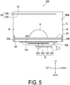
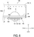
- FIG. 5 and FIG. 6 are diagrams illustrating a schematic cross section of the heating chamber 1 according to the present embodiment. More specifically, FIG. 5 illustrates a cross section of the heating chamber 1 taken along a plane orthogonal to the front-rear direction. FIG. 6 illustrates a cross section of the heating chamber 1 taken along a plane orthogonal to the left-right direction.
- the pull-out heating cooking apparatus 100 further includes a microwave supply unit 15 and a partitioning member 15B.
- the microwave supply unit 15 supplies microwaves to the heating cooking chamber 100A.
- the microwave supply unit 15 is positioned outside of the heating cooking chamber 100A via the bottom wall 1D.
- the microwave supply unit 15 includes a radiation chamber 15A, a magnetron 151, a waveguide 152, a rotary antenna 153, and an antenna motor 154.
- the magnetron 151 generates microwaves.
- the waveguide 152 propagates the microwaves generated by the magnetron 151 to the radiation chamber 15A.
- the radiation chamber 15A includes a radiation port 15C.
- the radiation port 15C has, for example, a square shape.
- the radiation port 15C is positioned below the heating cooking chamber 100A.
- the radiation port 15C is positioned at a substantially center portion of the bottom wall 1D.
- the rotary antenna 153 is accommodated in the radiation chamber 15A.
- the antenna motor 154 drives the rotary antenna 153.
- the rotary antenna 153 agitates microwaves and supplies the microwaves to the heating cooking chamber 100A through the radiation port 15C.
- the microwave supply unit 15 is provided below the heating cooking chamber 100A, and thus the object H to be heated can be irradiated with microwaves generated by the microwave supply unit 15 at a short distance. As a result, the object H to be heated can be efficiently heated.
- the partitioning member 15B covers the radiation port 15C.
- the partitioning member 15B need only have a shape that can cover the radiation port 15C.
- the partitioning member 15B is preferably a plate-like member. Further, when viewed from the vertical direction, the shape of the partitioning member 15B is, for example, a square shape.
- the material of the partitioning member 15B includes a ceramic or glass. As a result, because the material of the partitioning member 15B includes a ceramic or glass, the partitioning member 15B transmits microwaves. On the other hand, the materials of the radiation chamber 15A and the waveguide 152 include a metal.
- the pull-out heating cooking apparatus 100 further includes a grill unit 16.
- the grill unit 16 includes a heater 161 and an energization unit 162.
- the heater 161 is positioned in the heating cooking chamber 100A and heats the object H to be heated.
- the heater 161 is positioned at an upper portion in the heating cooking chamber 100A.
- the heater 161 has substantially a U shape when viewed from a vertical direction. In the present embodiment, three grill units 16 are disposed.
- the heater 161 is, for example, a sheathed heater.
- the energization unit 162 is positioned outside of the left wall 1B. The energization unit 162 energizes the heater 161.
- the energized heater 161 generates heat.
- the heater 161 is provided in an upper portion of the heating cooking chamber 100A, and the microwave supply unit 15 is provided below the heating cooking chamber 100A.
- the heater 161 does not inhibit an object H to be heated from being irradiated with microwaves and conducts heat generated by the heater 161 to an upper face of the object H to be heated, and thus the upper face of the object H to be heated can be efficiently heated.
- FIG. 7 is a block diagram illustrating a configuration of the pull-out heating cooking apparatus 100 according to the present embodiment.
- the pull-out heating cooking apparatus 100 has a "microwave heating mode” and a “grill heating mode” as heating cooking modes.
- the "microwave heating mode” is mainly a mode in which the object H to be heated is heated and cooked by radiating microwaves into the heating cooking chamber 100A.
- the "grill heating mode” is mainly a mode in which the object H to be heated is heated and cooked by conducting heat generated by the heater 161 to the object H to be heated.
- the control unit 5 controls a drive unit 133, the magnetron 151, the antenna motor 154, the energization unit 162, the drive motor 41, the operation panel 3, and the storage unit 6 by executing control programs stored in the storage unit 6.
- control unit 5 controls the driving of the microwave supply unit 15 and the driving of the grill unit 16. For example, in a case where the "microwave heating mode" is selected, the control unit 5 drives the magnetron 151 and the antenna motor 154. Further, in a case where the "grill heating mode” is selected, the control unit 5 energizes the energization unit 162.
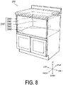
- FIG. 8 is a diagram illustrating an appearance of the cabinet 200 to which the pull-out heating cooking apparatus 100 according to the present embodiment is attached.
- the pull-out heating cooking apparatus 100 is installed in the cabinet 200 in built-in manner.
- the cabinet 200 includes an upper wall 200A, a lower wall 200B, a right wall 200C, a left wall 200D, and a rear wall 200E.
- the upper wall 200A, the lower wall 200B, the right wall 200C, the left wall 200D, and the rear wall 200E form an accommodation portion 200F.
- the accommodation portion 200F is a rectangular parallelepiped space in which the pull-out heating cooking apparatus 100 is attached.
- the present invention is useful in the field of a heating cooking apparatus, for example.
Abstract
Description
- The present invention relates to a heating cooking apparatus.
-
PTL 1 discloses a pull-out heating cooking apparatus. The pull-out heating cooking apparatus disclosed inPTL 1 includes a heating cooking apparatus main body and a pull-out body. The heating cooking apparatus main body includes a heating cooking chamber. The pull-out body can be drawn toward the outside of the heating cooking apparatus main body from a state where the pull-out body is accommodated in the heating cooking chamber. - Heating functions of the pull-out heating cooking apparatus disclosed in
PTL 1 include a microwave heating function and a rapid hot air heating function. The microwave heating function is a function of applying microwaves toward an object to be heated. A microwave radiation port is formed in a side wall of the heating cooking chamber. - PTL 1:
JP 2010-133634 A - Further, in recent years, there has been a demand for efficiently irradiating an object to be heated with microwaves.
- In light of the above problem, an object of the present invention is to provide a heating cooking apparatus that can efficiently irradiate an object to be heated with microwaves.
- A heating cooking apparatus of the present invention includes a heating cooking chamber and a microwave supply unit. An object to be heated is accommodated in the heating cooking chamber. The microwave supply unit includes a radiation port and supplies microwaves to the heating cooking chamber through the radiation port. The radiation port is positioned below the heating cooking chamber.
- According to the pull-out heating cooking apparatus of the present invention, an object to be heated can be efficiently irradiated with microwaves.
-
-
FIG. 1 is a perspective view illustrating an appearance of a pull-out heating cooking apparatus according to an embodiment of the present invention. -
FIG. 2 is a right side view illustrating the pull-out heating cooking apparatus according to the present embodiment. -
FIG. 3 is a top view illustrating the pull-out heating cooking apparatus according to the present embodiment. -
FIG. 4 is a perspective view of a pull-out body and a placing portion according to the present embodiment. -
FIG. 5 is a diagram illustrating a schematic cross section of a heating chamber according to the present embodiment. -
FIG. 6 is a diagram illustrating a schematic cross section of the heating chamber according to the present embodiment. -
FIG. 7 is a block diagram illustrating a configuration of the pull-out heating cooking apparatus according to the present embodiment. -
FIG. 8 is a diagram illustrating an appearance of a cabinet in which the pull-out heating cooking apparatus according to the present embodiment is built. -
FIG. 9 is a bottom view of the placing portion according to the present embodiment. - Hereinafter, an embodiment of a pull-out heating cooking apparatus according to the present invention will be described with reference to the drawings. In the drawings, the same or equivalent components are denoted by the same reference signs and description thereof will not be repeated.
- A pull-out
heating cooking apparatus 100 according to the present embodiment will be described with reference toFIG. 1 to FIG. 3 .FIG. 1 is a perspective view illustrating an appearance of the pull-outheating cooking apparatus 100 according to the present embodiment.FIG. 2 is a right side view illustrating the pull-outheating cooking apparatus 100 according to the present embodiment.FIG. 3 is a top view illustrating the pull-outheating cooking apparatus 100 according to the present embodiment. More specifically,FIG. 1 to FIG. 3 illustrate the pull-outheating cooking apparatus 100 in a state where a pull-outbody 2 is pulled out. Further,FIG. 1 illustrates the appearance of the pull-outheating cooking apparatus 100 when viewed from above obliquely from the right. The pull-outheating cooking apparatus 100 is one example of a heating cooking apparatus. - The pull-out
heating cooking apparatus 100 heats and cooks an object H to be heated. The object H to be heated is, for example, a food product. As illustrated inFIG. 1 , the pull-outheating cooking apparatus 100 includes aheating chamber 1, the pull-outbody 2, anoperation panel 3, acontrol unit 5, and astorage unit 6. - In the present embodiment, a side on which the
operation panel 3 of the pull-outheating cooking apparatus 100 is disposed is defined as a front side of the pull-outheating cooking apparatus 100, and a side opposite to the front side is defined as a rear side of the pull-outheating cooking apparatus 100. Further, a right side of the pull-outheating cooking apparatus 100 when the pull-outheating cooking apparatus 100 is viewed from the front side is defined as a right side, and a side opposite to the right side is defined as a left side of the pull-outheating cooking apparatus 100. Further, in a direction orthogonal to a front-rear direction and a left-right direction of the pull-outheating cooking apparatus 100, a side on which theoperation panel 3 is disposed is defined as an upper side of the pull-outheating cooking apparatus 100, and a side opposite to the upper side is defined as a lower side of the pull-outheating cooking apparatus 100. Note that these orientations do not limit the orientation of the pull-out heating cooking apparatus according to the present invention when in use. - As illustrated in
FIG. 1 to FIG. 3 , theheating chamber 1 is a box-like member. Specifically, theheating chamber 1 includes a rightouter wall 1G, a leftouter wall 1H, a topouter wall 1J, a bottomouter wall 1F, and a backouter wall 1K. Theheating chamber 1 also includes aheating cooking chamber 100A therein. - The
heating cooking chamber 100A includes anaccommodation space 120 that accommodates the object H to be heated. Theaccommodation space 120 is a space that can accommodate the object to be heated H and has a predetermined volume. Specifically, theheating cooking chamber 100A includes aright wall 1A, aleft wall 1B, atop wall 1C, abottom wall 1D, and aback wall 1E. The shape of theheating cooking chamber 100A is, for example, a substantially rectangular parallelepiped shape. Materials of theright wall 1A, theleft wall 1B, thetop wall 1C, thebottom wall 1D, and theback wall 1E are, for example, a metal. The front side of theheating cooking chamber 100A is opened for allowing the object to be heated H to be inserted and removed. - The
heating chamber 1 further includes a space between thebottom wall 1D and the bottomouter wall 1F. Theheating chamber 1 further includes a space between theright wall 1A and the rightouter wall 1G. Theheating chamber 1 further includes a space between theleft wall 1B and the leftouter wall 1H. Theheating chamber 1 further includes a space between thetop wall 1C and the topouter wall 1J. Theheating chamber 1 further includes a space between theback wall 1E and the backouter wall 1K. - The
operation panel 3 includes an operation unit and a display portion. The operation unit receives an operation from a user. The operation unit includes various types of keys. The display portion displays various pieces of information. The display portion includes a liquid crystal panel. Theoperation panel 3 is located on an upper portion of a front face of theheating chamber 1. - The
storage unit 6 includes a random access memory (RAM) and a read only memory (ROM). Thestorage unit 6 stores control programs used for controlling operations of each part of the pull-outheating cooking apparatus 100. Thestorage unit 6 stores setting information input when theoperation panel 3 is operated. - The
control unit 5 is a hardware circuit that includes a processor such as a central processing unit (CPU). Thecontrol unit 5 executes a control program stored in thestorage unit 6. - Subsequently, the pull-out
body 2 and a placingportion 22 according to the present embodiment will be described with reference toFIG. 1 to FIG. 4 .FIG. 4 is a perspective view of the pull-outbody 2 and the placingportion 22 according to the present embodiment. As illustrated inFIG. 1 to FIG. 4 , the pull-outheating cooking apparatus 100 further includes the placingportion 22. In addition, as illustrated inFIG. 1 to FIG. 4 , the pull-outbody 2 is freely pulled out from theheating cooking chamber 100A along a predetermined direction D1. The predetermined direction D1 is a direction along a front-rear direction. More specifically, the pull-outbody 2 can be pulled out and pulled in with respect to theheating chamber 1. Specifically, the pull-outbody 2 includes a pull-outmain body 20. The pull-outmain body 20 includes adoor portion 21 and asupport portion 23. - The object H to be heated can be placed on the placing
portion 22. The placingportion 22 is, for example, a plate-like member made of a ceramic, glass, or a synthetic resin, and is preferably a plate-like member made of a ceramic or glass. As a result, the placingportion 22 transmits microwaves. In addition, the placingportion 22 is transparent or translucent. The term "translucent" includes color transparency. - The
door portion 21 can open and close an opening on the front side of theheating cooking chamber 100A. Thedoor portion 21 is a substantially rectangular plate-like member. Thedoor portion 21 includes afront face 21A and arear face 21B. Thedoor portion 21 opens the opening on the front side of theheating cooking chamber 100A in a state where the pull-outbody 2 is pulled out of theheating cooking chamber 100A. Thedoor portion 21 closes the opening on the front side of theheating cooking chamber 100A in a state where the pull-outbody 2 is pulled into theheating cooking chamber 100A. Meanwhile, in a state where the pull-outbody 2 is pushed into theheating cooking chamber 100A, a distance between thetop wall 1C and thebottom wall 1D is shorter than a distance between theback wall 1E and therear face 21B. - The
support portion 23 is fixed to therear face 21B of thedoor portion 21, and supports a peripheral portion of the placingportion 22 such that the placingportion 22 is held in a horizontal state. Specifically, thesupport portion 23 includes abase plate portion 23A, aback plate portion 23B, aright plate portion 23C, aleft plate portion 23D, and a pair ofrollers 23E. - The
base plate portion 23A includes a rectangular opening 23A1. The rectangular opening 23A1 is positioned at a substantially center portion of thebase plate portion 23A. - The
back plate portion 23B, theright plate portion 23C, and theleft plate portion 23D are erected upward from a peripheral portion of thebase plate portion 23A. The placingportion 22 is fitted between thedoor portion 21, theback plate portion 23B, theright plate portion 23C, and theleft plate portion 23D. In addition, the peripheral portion of the placingportion 22 is fixed to the upper face of the peripheral portion of thebase plate portion 23A. - The pair of
rollers 23E are rotated as the pull-outbody 2 moves. Specifically, the pair ofrollers 23E include a right roller 23E1 and a left roller 23E2. In addition, the right roller 23E1 is attached to a rear end of theright plate portion 23C. The left roller 23E2 is attached to a rear end of theleft plate portion 23D. - The placing
portion 22 and thesupport portion 23 are pulled out of theheating cooking chamber 100A to the outside by pulling out the pull-outbody 2. The placingportion 22 and thesupport portion 23 are accommodated in theheating cooking chamber 100A in a state where the pull-outbody 2 is pulled in. As described above, the placingportion 22 is transparent or translucent, and thus a user or the like can visually recognize an object present below the placingportion 22. As a result, the user or the like can easily clean thebottom wall 1D when thebottom wall 1D of theheating cooking chamber 100A is dirty. In addition, an object H to be heated that has fallen onto thebottom wall 1D can be removed before carbonization. - The pull-out
body 2 further includes a pair ofslide members 24 and asupport member 25 in addition to the pull-outmain body 20. - Further, the pair of
slide members 24 regulate the movement direction of the pull-outbody 2 in the front-rear direction. The pair ofslide members 24 are fixed to therear face 21B of thedoor portion 21. - Specifically, the pair of
slide members 24 includes a right slide member 241 and a left slide member 242. Each of the right slide member 241 and the left slide member 242 is, for example, a member having the front-rear direction as a longitudinal direction. The right slide member 241 and the left slide member 242 oppose each other in the left-right direction. One end portion of the right slide member 241 is attached to a right edge portion of therear face 21B of thedoor portion 21. One end portion of the left slide member 242 is attached to a left edge portion of therear face 21B of thedoor portion 21. - Meanwhile, the
heating chamber 1 further includes aright slide rail 11 and aleft slide rail 12. Theright slide rail 11 is fixed in a space between theright wall 1A and the rightouter wall 1G. Theleft slide rail 12 is fixed in a space between theleft wall 1B and the leftouter wall 1H. Each of theright slide rail 11 and theleft slide rail 12 is a member having the front-rear direction as a longitudinal direction. The right slide member 241 is supported to be slidable along theright slide rail 11. The left slide member 242 is supported to be slidable along theleft slide rail 12. - The
support member 25 supports the pull-outmain body 20. More specifically, thesupport member 25 regulates the movement direction of the pull-outbody 2 in the predetermined direction D1. One end portion of thesupport member 25 is attached at a center portion in the left-right direction of therear face 21B of thedoor portion 21 and below the placingportion 22. Thesupport member 25 is, for example, a plate-like member having the front-rear direction as a longitudinal direction. Thesupport member 25 includes a rack portion. The rack portion includes a plurality of teeth. Thesupport member 25 may be a single plate-like member or a plurality of plate-like members. - Meanwhile, the
heating chamber 1 further includes adrive mechanism 4. Thedrive mechanism 4 drives thesupport member 25. Thedrive mechanism 4 is positioned below theheating cooking chamber 100A. Specifically, thedrive mechanism 4 is accommodated in a space between thebottom wall 1D and the bottomouter wall 1F. For example, thedrive mechanism 4 includes adrive motor 41, a pinion, and adrive rail 42. Thedrive rail 42 is fixed in a space between thebottom wall 1D and the bottomouter wall 1F. Thedrive rail 42 is a member having the front-rear direction as a longitudinal direction. Thesupport member 25 is supported to be slidable along thedrive rail 42. The pinion is attached to a tip end portion of thedrive motor 41. The pinion engages with the rack portion of thesupport member 25. Furthermore, thesupport member 25 moves in the front-rear direction when the pinion rotates. As a result, the pull-outbody 2 is in an open state or a closed state. Note that thedrive mechanism 4 may drive at least one of thesupport member 25, the right slide member 241, and the left slide member 242. Further, in a case where the right slide member 241 and the left slide member 242 are driven, thedrive mechanism 4 may be positioned on the side of theheating cooking chamber 100A. - As described above, the placing
portion 22 is transparent or translucent, and thus a user or the like can visually recognize thesupport member 25 that is present below the placingportion 22. As a result, a manufacturer and the like can easily insert thesupport member 25 into thedrive rail 42 provided at the lower center on the front face side of theheating chamber 1 in order to align thesupport member 25 and the pinion. - Next, the
heating chamber 1 according to the present embodiment will be further described with reference toFIG. 1 to FIG. 6 .FIG. 5 andFIG. 6 are diagrams illustrating a schematic cross section of theheating chamber 1 according to the present embodiment. More specifically,FIG. 5 illustrates a cross section of theheating chamber 1 taken along a plane orthogonal to the front-rear direction.FIG. 6 illustrates a cross section of theheating chamber 1 taken along a plane orthogonal to the left-right direction. - As illustrated in
FIG. 5 andFIG. 6 , the pull-outheating cooking apparatus 100 further includes amicrowave supply unit 15 and apartitioning member 15B. Themicrowave supply unit 15 supplies microwaves to theheating cooking chamber 100A. - The
microwave supply unit 15 is positioned outside of theheating cooking chamber 100A via thebottom wall 1D. Themicrowave supply unit 15 includes aradiation chamber 15A, amagnetron 151, awaveguide 152, arotary antenna 153, and anantenna motor 154. Themagnetron 151 generates microwaves. Thewaveguide 152 propagates the microwaves generated by themagnetron 151 to theradiation chamber 15A. - The
radiation chamber 15A includes aradiation port 15C. Theradiation port 15C has, for example, a square shape. In addition, theradiation port 15C is positioned below theheating cooking chamber 100A. Specifically, theradiation port 15C is positioned at a substantially center portion of thebottom wall 1D. Therotary antenna 153 is accommodated in theradiation chamber 15A. Theantenna motor 154 drives therotary antenna 153. Therotary antenna 153 agitates microwaves and supplies the microwaves to theheating cooking chamber 100A through theradiation port 15C. - As described above, the
microwave supply unit 15 is provided below theheating cooking chamber 100A, and thus the object H to be heated can be irradiated with microwaves generated by themicrowave supply unit 15 at a short distance. As a result, the object H to be heated can be efficiently heated. - The partitioning
member 15B covers theradiation port 15C. The partitioningmember 15B need only have a shape that can cover theradiation port 15C. The partitioningmember 15B is preferably a plate-like member. Further, when viewed from the vertical direction, the shape of thepartitioning member 15B is, for example, a square shape. - The material of the
partitioning member 15B includes a ceramic or glass. As a result, because the material of thepartitioning member 15B includes a ceramic or glass, the partitioningmember 15B transmits microwaves. On the other hand, the materials of theradiation chamber 15A and thewaveguide 152 include a metal. - The pull-out
heating cooking apparatus 100 further includes agrill unit 16. Specifically, thegrill unit 16 includes aheater 161 and anenergization unit 162. Theheater 161 is positioned in theheating cooking chamber 100A and heats the object H to be heated. Specifically, theheater 161 is positioned at an upper portion in theheating cooking chamber 100A. Theheater 161 has substantially a U shape when viewed from a vertical direction. In the present embodiment, threegrill units 16 are disposed. Theheater 161 is, for example, a sheathed heater. Theenergization unit 162 is positioned outside of theleft wall 1B. Theenergization unit 162 energizes theheater 161. The energizedheater 161 generates heat. - According to the pull-out
heating cooking apparatus 100 of the present invention, theheater 161 is provided in an upper portion of theheating cooking chamber 100A, and themicrowave supply unit 15 is provided below theheating cooking chamber 100A. Thus, theheater 161 does not inhibit an object H to be heated from being irradiated with microwaves and conducts heat generated by theheater 161 to an upper face of the object H to be heated, and thus the upper face of the object H to be heated can be efficiently heated. - A configuration of the pull-out
heating cooking apparatus 100 will be described in detail with reference toFIG. 7. FIG. 7 is a block diagram illustrating a configuration of the pull-outheating cooking apparatus 100 according to the present embodiment. - In the present embodiment, the pull-out
heating cooking apparatus 100 has a "microwave heating mode" and a "grill heating mode" as heating cooking modes. The "microwave heating mode" is mainly a mode in which the object H to be heated is heated and cooked by radiating microwaves into theheating cooking chamber 100A. The "grill heating mode" is mainly a mode in which the object H to be heated is heated and cooked by conducting heat generated by theheater 161 to the object H to be heated. - The
control unit 5 controls a drive unit 133, themagnetron 151, theantenna motor 154, theenergization unit 162, thedrive motor 41, theoperation panel 3, and thestorage unit 6 by executing control programs stored in thestorage unit 6. - More specifically, the
control unit 5 controls the driving of themicrowave supply unit 15 and the driving of thegrill unit 16. For example, in a case where the "microwave heating mode" is selected, thecontrol unit 5 drives themagnetron 151 and theantenna motor 154. Further, in a case where the "grill heating mode" is selected, thecontrol unit 5 energizes theenergization unit 162. - Next, a
cabinet 200 to which the pull-outheating cooking apparatus 100 is attached will be described with reference toFIG. 8. FIG. 8 is a diagram illustrating an appearance of thecabinet 200 to which the pull-outheating cooking apparatus 100 according to the present embodiment is attached. - The pull-out
heating cooking apparatus 100 is installed in thecabinet 200 in built-in manner. As illustrated inFIG. 8 , thecabinet 200 includes anupper wall 200A, alower wall 200B, a right wall 200C, a left wall 200D, and arear wall 200E. Theupper wall 200A, thelower wall 200B, the right wall 200C, the left wall 200D, and therear wall 200E form anaccommodation portion 200F. Theaccommodation portion 200F is a rectangular parallelepiped space in which the pull-outheating cooking apparatus 100 is attached. - An embodiment of the present invention has been described above with reference to the drawings. However, the present invention is not limited to the embodiment described above, and the present invention can be implemented in various modes without departing from the gist of the disclosure. The drawings primarily schematically illustrate each of the constituent elements for the sake of easier understanding, and the thickness, length, quantity, and the like of each of the illustrated constituent elements are different from the actual thickness, length, quantity, and the like by reason of creation of the drawings. The material, shape, dimensions, and the like of each of the constituent elements illustrated in the embodiment described above are merely exemplary and are not particularly limiting, and various modifications can be made within the scope not departing from the effects of the present invention in essence.
-
- (1) As described with reference to
FIG. 1 to FIG. 8 , the placingportion 22 is transparent or translucent, but the present invention is not limited thereto. Position information may be provided on the lower face of the transparent ortranslucent placing portion 22.FIG. 9 is a bottom view of the placingportion 22 according to the present embodiment. Position information is provided on the lower face of the placingportion 22. The position information indicates the position at which the object H to be heated is to be placed. The position information is, for example, amark 22a. The shape of themark 22a is, for example, a circular ring. For example, themark 22a is printed on the lower face of the placingportion 22. As described above, themicrowave supply unit 15 is provided below theheating cooking chamber 100A and can emit microwaves at a short distance. Further, the object H to be heated can be more efficiently heated by providing themark 22a for guiding the object H to be heated to a point which is most efficiently irradiated with microwaves. In addition, themark 22a is provided on the lower face of the placingportion 22 because the placingportion 22 is transparent or translucent, and thus themark 22a hardly becomes dirty and can be prevented from wearing off. - (2) As described with reference to
FIG. 1 to FIG. 9 , the pull-outheating cooking apparatus 100 may further include an air sending unit that supplies hot air to theheating cooking chamber 100A. - (3) As described with reference to
FIG. 1 to FIG. 9 , the pull-outheating cooking apparatus 100 includes thegrill unit 16, but the present invention is not limited thereto. The pull-outheating cooking apparatus 100 may not include thegrill unit 16. - (4) As described with reference to
FIG. 1 to FIG. 9 , the placingportion 22 is fixed onto thebase plate portion 23A of thesupport portion 23, but the present invention is not limited thereto. For example, the placingportion 22 may be detachably placed on thesupport portion 23, or may be placed on thepartitioning member 15B. - The present invention is useful in the field of a heating cooking apparatus, for example.
-
- 1 Heating chamber
- 2 Pull-out body
- 4 Drive mechanism
- 15 Microwave supply unit
- 15B Partitioning member
- 15C Radiation port
- 21 Door portion
- 22 Placing portion
- 23 Support portion
- 25 Support member
- 100 Pull-out heating cooking apparatus
- 100A Heating cooking chamber
Claims (5)
- A heating cooking apparatus comprising:a heating cooking chamber configured to accommodate an object to be heated; anda microwave supply unit including a radiation port and configured to supply microwaves to the heating cooking chamber through the radiation port,wherein the radiation port is positioned below the heating cooking chamber.
- The heating cooking apparatus according to claim 1, further comprising:a partitioning member configured to cover the radiation port; anda placing portion on which the object to be heated is placed,wherein the partitioning member and the placing portion transmit the microwaves, andthe placing portion is transparent or translucent.
- The heating cooking apparatus according to claim 2, further comprising:a pull-out body configured to be freely pulled out from the heating cooking chamber in a predetermined direction,wherein the pull-out body includesa pull-out main body configured to support the placing portion, anda support member configured to support the pull-out main body,the placing portion is able to be pulled out from the heating cooking chamber and is able to be accommodated in the heating cooking chamber, andthe support member is positioned below the heating cooking chamber.
- The heating cooking apparatus according to claim 2 or 3,
wherein position information indicating a position at which the object to be heated is to be placed is provided on a lower face of the placing portion. - The heating cooking apparatus according to any one of claims 1 to 4, further comprising:a heater positioned in the heating cooking chamber and configured to heat the object to be heated,wherein the heater is positioned at an upper portion of the heating cooking chamber.
Applications Claiming Priority (2)
| Application Number | Priority Date | Filing Date | Title |
|---|---|---|---|
| JP2019141451 | 2019-07-31 | ||
| PCT/JP2020/028700 WO2021020343A1 (en) | 2019-07-31 | 2020-07-27 | Heating cooker |
Publications (2)
| Publication Number | Publication Date |
|---|---|
| EP4006424A1 true EP4006424A1 (en) | 2022-06-01 |
| EP4006424A4 EP4006424A4 (en) | 2022-09-28 |
Family
ID=74230383
Family Applications (1)
| Application Number | Title | Priority Date | Filing Date |
|---|---|---|---|
| EP20846465.1A Pending EP4006424A4 (en) | 2019-07-31 | 2020-07-27 | Heating cooker |
Country Status (6)
| Country | Link |
|---|---|
| US (1) | US20220205639A1 (en) |
| EP (1) | EP4006424A4 (en) |
| JP (1) | JPWO2021020343A1 (en) |
| CN (1) | CN114144620A (en) |
| CA (1) | CA3149156A1 (en) |
| WO (1) | WO2021020343A1 (en) |
Family Cites Families (11)
| Publication number | Priority date | Publication date | Assignee | Title |
|---|---|---|---|---|
| CA1111505A (en) * | 1977-08-01 | 1981-10-27 | Junzo Tanaka | Microwave oven having a radiation leak-proof drawer type door |
| JPS5942566Y2 (en) * | 1979-08-15 | 1984-12-13 | 株式会社東芝 | High frequency heating device |
| JPH07117246B2 (en) * | 1991-07-31 | 1995-12-18 | 株式会社フジマック | Batch type combined heating device |
| FR2686400B3 (en) * | 1992-01-17 | 1994-04-01 | Moulinex Sa | SUPPORT RECEIVING A FROZEN FOOD PREPARATION MOUNTED IN A DEFROSTING AND HEATING MACHINE. |
| KR20040061358A (en) * | 2002-12-30 | 2004-07-07 | 엘지전자 주식회사 | A structure and a method of printing logo on door for electronic products |
| JP2008257972A (en) * | 2007-04-04 | 2008-10-23 | Matsushita Electric Ind Co Ltd | Microwave heating apparatus |
| JP2010133634A (en) | 2008-12-04 | 2010-06-17 | Sharp Corp | Drawer type cooking device |
| JP5593710B2 (en) * | 2010-01-27 | 2014-09-24 | パナソニック株式会社 | Microwave heating cooker |
| JP5899426B2 (en) * | 2011-05-12 | 2016-04-06 | パナソニックIpマネジメント株式会社 | Cooker |
| JP2014052152A (en) * | 2012-09-10 | 2014-03-20 | Hitachi Appliances Inc | Heating cooker |
| WO2016031737A1 (en) * | 2014-08-29 | 2016-03-03 | シャープ株式会社 | Cooking device |
-
2020
- 2020-07-27 CN CN202080052979.0A patent/CN114144620A/en active Pending
- 2020-07-27 CA CA3149156A patent/CA3149156A1/en active Pending
- 2020-07-27 WO PCT/JP2020/028700 patent/WO2021020343A1/en unknown
- 2020-07-27 JP JP2021535328A patent/JPWO2021020343A1/ja active Pending
- 2020-07-27 US US17/631,110 patent/US20220205639A1/en active Pending
- 2020-07-27 EP EP20846465.1A patent/EP4006424A4/en active Pending
Also Published As
| Publication number | Publication date |
|---|---|
| US20220205639A1 (en) | 2022-06-30 |
| EP4006424A4 (en) | 2022-09-28 |
| WO2021020343A1 (en) | 2021-02-04 |
| CA3149156A1 (en) | 2021-02-04 |
| CN114144620A (en) | 2022-03-04 |
| JPWO2021020343A1 (en) | 2021-02-04 |
Similar Documents
| Publication | Publication Date | Title |
|---|---|---|
| EP4006424A1 (en) | Heating cooker | |
| EP4279818A1 (en) | Cooking device | |
| US20220316710A1 (en) | Heating cooking apparatus | |
| US20230067149A1 (en) | Heating cooking apparatus | |
| EP4332439A2 (en) | Heating cooking apparatus | |
| US20220330394A1 (en) | Heating cooking apparatus | |
| EP4299987A1 (en) | Thermal cooker | |
| EP4299988A1 (en) | Cooker | |
| US20220325902A1 (en) | Heating cooking apparatus | |
| EP4036476A1 (en) | Cooking apparatus and built-in cooking system | |
| EP4269876A1 (en) | Heat cooker | |
| EP4253842A1 (en) | Heating cooker | |
| US20220325903A1 (en) | Heating cooking apparatus | |
| EP4012263A1 (en) | Heating cooking device | |
| EP4102138A1 (en) | Heating cooking device | |
| EP4261460A1 (en) | Cooker | |
| EP4279816A1 (en) | Cooker | |
| CN114207358A (en) | Drawer type heating cooker |
Legal Events
| Date | Code | Title | Description |
|---|---|---|---|
| STAA | Information on the status of an ep patent application or granted ep patent |
Free format text: STATUS: THE INTERNATIONAL PUBLICATION HAS BEEN MADE |
|
| TPAC | Observations filed by third parties |
Free format text: ORIGINAL CODE: EPIDOSNTIPA |
|
| PUAI | Public reference made under article 153(3) epc to a published international application that has entered the european phase |
Free format text: ORIGINAL CODE: 0009012 |
|
| STAA | Information on the status of an ep patent application or granted ep patent |
Free format text: STATUS: REQUEST FOR EXAMINATION WAS MADE |
|
| 17P | Request for examination filed |
Effective date: 20220217 |
|
| AK | Designated contracting states |
Kind code of ref document: A1 Designated state(s): AL AT BE BG CH CY CZ DE DK EE ES FI FR GB GR HR HU IE IS IT LI LT LU LV MC MK MT NL NO PL PT RO RS SE SI SK SM TR |
|
| A4 | Supplementary search report drawn up and despatched |
Effective date: 20220831 |
|
| RIC1 | Information provided on ipc code assigned before grant |
Ipc: F24C 15/16 20060101ALI20220825BHEP Ipc: F24C 15/02 20060101ALI20220825BHEP Ipc: F24C 7/02 20060101ALI20220825BHEP Ipc: H05B 6/72 20060101ALI20220825BHEP Ipc: H05B 6/64 20060101AFI20220825BHEP |
|
| DAV | Request for validation of the european patent (deleted) | ||
| DAX | Request for extension of the european patent (deleted) |