EP4006398B1 - Spacer for pipes - Google Patents
Spacer for pipes Download PDFInfo
- Publication number
- EP4006398B1 EP4006398B1 EP21209745.5A EP21209745A EP4006398B1 EP 4006398 B1 EP4006398 B1 EP 4006398B1 EP 21209745 A EP21209745 A EP 21209745A EP 4006398 B1 EP4006398 B1 EP 4006398B1
- Authority
- EP
- European Patent Office
- Prior art keywords
- pipe
- ring half
- spacer
- ring
- support
- Prior art date
- Legal status (The legal status is an assumption and is not a legal conclusion. Google has not performed a legal analysis and makes no representation as to the accuracy of the status listed.)
- Active
Links
- 125000006850 spacer group Chemical group 0.000 title claims description 37
- 229920002457 flexible plastic Polymers 0.000 claims 1
- 239000007789 gas Substances 0.000 description 2
- 230000004323 axial length Effects 0.000 description 1
- 230000003139 buffering effect Effects 0.000 description 1
- 230000007423 decrease Effects 0.000 description 1
- 231100001261 hazardous Toxicity 0.000 description 1
- 238000009413 insulation Methods 0.000 description 1
- 239000000463 material Substances 0.000 description 1
- 239000000203 mixture Substances 0.000 description 1
- 238000012986 modification Methods 0.000 description 1
- 230000004048 modification Effects 0.000 description 1
- 230000001681 protective effect Effects 0.000 description 1
- 238000010926 purge Methods 0.000 description 1
- 230000000284 resting effect Effects 0.000 description 1
- 231100000331 toxic Toxicity 0.000 description 1
- 230000002588 toxic effect Effects 0.000 description 1
- 238000004804 winding Methods 0.000 description 1
Images

Classifications
-
- F—MECHANICAL ENGINEERING; LIGHTING; HEATING; WEAPONS; BLASTING
- F16—ENGINEERING ELEMENTS AND UNITS; GENERAL MEASURES FOR PRODUCING AND MAINTAINING EFFECTIVE FUNCTIONING OF MACHINES OR INSTALLATIONS; THERMAL INSULATION IN GENERAL
- F16L—PIPES; JOINTS OR FITTINGS FOR PIPES; SUPPORTS FOR PIPES, CABLES OR PROTECTIVE TUBING; MEANS FOR THERMAL INSULATION IN GENERAL
- F16L7/00—Supporting of pipes or cables inside other pipes or sleeves, e.g. for enabling pipes or cables to be inserted or withdrawn from under roads or railways without interruption of traffic
Definitions
- the invention relates to a spacer for pipes according to the preamble of claim 1.
- Spacers for pipes are already known and in use in a variety of forms and designs. These are usually devices that are arranged around the pipe in question, based on the model of a circular clamp.
- a spacer for a media-carrying pipe for laying the pipe in a protective pipe is disclosed.
- US 5 803 1 27 A discloses a piping system for the transport of toxic and hazardous gases, wherein an inner line is separated from an outer line by a spacer so that purge gases can flow between the lines.
- thermoly insulating pipeline which has a spacer arrangement 10 with a thermal insulation strip 18.
- the aim of the present invention is to overcome the disadvantages of the prior art.
- a device is to be provided which allows a pipe to be easily spaced apart from the surrounding medium in its bedding.
- the device is to be light and inexpensive. Furthermore, it is to be possible to arrange the device in the intended manner even after the pipe has been bedding. Furthermore, no tools are to be required to install the device and the device should consist of as few components as possible, preferably be one piece.
- the spacer according to the invention is designed in the shape of a spiral spring in the area of a spiral support, whereby the spiral support has one and a half ring turns. Of course, several turns can also be provided.
- each end of the spiral support there is a raw support element which, due to its concavely curved holder, is ideally suited to be placed on a pipe, for example a drain pipe, and can also be fixed in place.
- the spiral support consists of a first ring half, a second ring half and a third ring half. These three identically designed ring halves together form a spiral support with one and a half ring turns.
- the first ring half is connected at one end to the first pipe support element via an angle connection and at the other end to the second ring half via a ring half connection.
- the second ring half is connected at one end via a further angle connection to the second pipe support element and at the other end via a further ring half connection to the second ring half.
- the angle connections are designed in such a way that they widen from an outer side, which is the side of the spacer according to the invention that faces the medium to be spaced, towards an inner side, which is the side that faces the pipe, and in the axial direction.
- This angled arrangement advantageously ensures that a comparatively large area of the pipe to be spaced can be spaced from the medium.
- the pipe support elements include a cable tie holder.
- This cable tie holder is channel-shaped and allows the pipe support elements to be reliably fixed to a pipe using a suitable cable tie. Cable tie holder designed in two stages so that cable ties of different sizes can be held securely in place.
- the spacer according to the invention preferably consists of a suitable plastic or a suitable plastic mixture. It is provided that the plastic has properties that allow the pipe support elements to be arranged on a pipe using cable ties in the area of the cable tie holder and also ensures sufficient flexibility of the spiral support so that the spacer according to the invention can be placed on a pipe directly at the intended position and does not have to be pushed on from one end of the pipe.
- the spiral support consists of a flexible band.
- This flexible band has spacer springs at regular intervals for resting on a pipe, i.e. on the pipe side. These spacer springs rest on a surface of a pipe and, held by the flexible band, space the pipe from the medium to be spaced apart.
- the spacer according to the invention which is equipped with a flexible band as a spiral support, can be used for different pipe diameters. Only the number of turns changes depending on the pipe diameter. For small pipe diameters, the flexible band is placed several times around the pipe; for large pipe diameters, the number of turns decreases accordingly. The only important thing is that at least one turn can be completed. This means that different spacers do not have to be brought along if it is unclear which pipes with which pipe diameters are to be spaced apart.
- the springs arranged at regular intervals on the flexible band have a buffering function in the direction of the medium in question.
- the distance between the flexible band and the pipe can be precisely determined and set using the length of the springs.
- a spiral support designed as a flexible band with springs can therefore be used when the diameters of the pipes to be spaced are not known or no other suitable spacers are available.
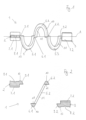
- FIG. 1 a spacer 1 according to the invention is shown.
- this is designed in the shape of a spiral spring, with the spiral support 4 having one and a half ring turns.
- a pipe support element 2, 3 is arranged at each end of the spiral support 4, i.e. a first pipe support element 2 at one end and a second pipe support element 3 at the other end.
- the first pipe receiving element 2 is connected to the spiral support 4 via a first angle connection 9.1.
- the second pipe receiving element 3 is connected to the spiral support 4 at the other end via a second angle connection 9.2.
- the spiral support 4 consists of a first ring half 5.1, a second ring half 5.2 and a third ring half 5.3. These three identically designed ring halves 5.1, 5.2, 5.3 together form one and a half Ring windings.
- the first ring half 5.1 and the third ring half 5.3 are each connected at one end to the second ring half 5.2 arranged between them via a ring half connection 6.1, 6.2.
- the ring half connections 6.1 and 6.2 are designed in such a way that they widen in a tangential direction from an outer side 10 of the ring halves 5.1, 5.2, 5.3 towards an inner side 11 of the ring halves 5.1, 5.2, 5.3.
- the outside 10 refers to the side that faces away from a pipe and comes into contact with the medium to be spaced apart.
- the inside 11 refers to the side that comes into contact with the pipe.
- Figure 2 is a partial sectional view of the spacer 1 according to the invention along a section line A of Figure 1 shown.
- first pipe support element 2 the second pipe support element 3 and the second ring half 5.2 with the two ring half connections 6.1 and 6.2.
- the two identically designed pipe support elements 2 and 3 have a cable tie holder 8.1, 8.2 on the outside 10.
- the cable tie holder 8.1, 8.2 is embedded in the pipe support element 2, 3 as a two-stage channel.
- the cable tie holder 8.1, 8.2 runs tangentially to a pipe to be spaced apart when the spacer is arranged on a pipe.
- the two-stage nature of the cable tie holder 8.1, 8.2 enables In the present embodiment, a slip-proof arrangement of cable ties of different widths.
- the pipe support element 2, 3 comprises a support 7.1, 7.2 that is curved concavely towards an outer side 10 opposite the cable tie holder 8.1, 8.2.
- the curved support 7.1, 7.2 is therefore arranged on the inner side 11 and, in particular due to the concave curvature, allows optimal support on a pipe that is to be spaced apart.
- the pipe support elements 2, 3 comprise an angle connection 9.1, 9.2.
- the angle connection 9.1, 9.2 widens from the outside 10 towards the inside 11 and in the axial direction, i.e. in the direction of the cutting line A.
- the ring halves 5.1 and 5.3 are also connected at an angle of 40 to 50 degrees, preferably at an angle of 45 degrees, to the first and second pipe support elements 2, 3.
- the ring half 5.1 can also be seen when looking at the inner side 11. This is connected at one end to the ring half connection 6.1 and at the other end to the ring half connection 6.2.
- the ring half 5.2 is connected to the other two ring halves 5.1 and 5.3 via the ring half connections 6.1 and 6.2.
- the ring half connections 6.1 and 6.2 widen from the outer side 10 towards the inner side 11, so that the ring halves 5.1, 5.2, 5.3 are connected at an angle of 40 to 50 degrees to one another, preferably at an angle of 45 degrees to one another.
- FIG. 3 a side view of the spacer 1 according to the invention is visible, wherein the view runs in the axial direction through the turns of the spiral support 4.
- the shape of the two pipe support elements 2 and 3 is particularly visible, with the supports 7.1 and 7.2 curved concavely towards the inner side 11 being visible.
- the spacer 1 according to the invention is placed around a pipe to be spaced apart, whereby this is possible due to the flexible material properties of the spacer 1 according to the invention by simply pushing it onto the desired position of the pipe. Pushing it onto the pipe from an axial direction, as is the case with most systems based on a rigid ring, is therefore not necessary. Thanks to its flexibility, the spacer 1 according to the invention can simply be placed onto a pipe at the desired position so that it surrounds it.
- the spacer 1 according to the invention is placed in the intended position around a pipe, it is arranged there using conventional cable ties. To do this, a first cable tie is placed around the pipe and the first pipe support element 2 in the area of the cable tie holder 8.1 and tightened.
- the second pipe support element 3 is then spaced apart in the axial direction along the pipe from the first pipe support element 2, which has already been fixed to the pipe, until the ring half connections 6.1 and 6.2 have contact with the pipe on their inner side 11. As soon as this contact is made, the position is found at which the second pipe support element 3 also is secured to the pipe with a cable tie in the area of the cable tie holder 8.2.
- the number of ring halves 5 included can be more than three. This would extend the axial length of the spacer if necessary.
- the angle formed by the ring half connections 6.1 and 6.2 and the angle connections 9.1 and 9.2 can also vary.
Landscapes
- Engineering & Computer Science (AREA)
- General Engineering & Computer Science (AREA)
- Mechanical Engineering (AREA)
- Supports For Pipes And Cables (AREA)
Description
Die Erfindung betrifft einen Abstandshalter für Rohre nach dem Oberbegriff des Anspruchs 1.The invention relates to a spacer for pipes according to the preamble of
Abstandshalter für Rohre sind bereits in vielfältiger Form und Ausgestaltung bekannt und gebräuchlich. Meist handelt es sich dabei um Vorrichtungen die nach dem Vorbild einer kreisrunden Schelle um das zu beanstandende Rohr angeordnet werden. So wird beispielsweise in der
In der
In der
Die Aufgabe der vorliegenden Erfindung ist es, die Nachteile aus dem Stand der Technik zu überwinden. Insbesondere soll eine Vorrichtung bereitgestellt werden, die es erlaubt ein Rohr auf einfache Weise in seiner Bettung zu dem umgebenden Medium zu beabstanden. Dabei soll die Vorrichtung leicht und kostengünstig sein. Weiterhin soll es möglich sein die Vorrichtung auch nach der Bettung des Rohres in vorgesehener Weise anzuordnen. Ferner sollen zur Installation der Vorrichtung keine Werkzeuge notwendig sein und die Vorrichtung soll aus möglichst wenigen Bestandteilen bestehen, vorzüglich einstückig sein.The aim of the present invention is to overcome the disadvantages of the prior art. In particular, a device is to be provided which allows a pipe to be easily spaced apart from the surrounding medium in its bedding. The device is to be light and inexpensive. Furthermore, it is to be possible to arrange the device in the intended manner even after the pipe has been bedding. Furthermore, no tools are to be required to install the device and the device should consist of as few components as possible, preferably be one piece.
Zur Lösung der Aufgabe führen die Merkmale nach dem Anspruch 1. Vorteilhafte Ausgestaltungen sind in den Unteransprüchen beschrieben.The features according to
Der erfindungsgemässe Abstandshalter ist im Bereich einer Spiralauflage spiralfederförmig ausgebildet, wobei die Spiralauflage eineinhalb Ringwindungen aufweist. Natürlich können auch mehre Windungen vorgesehen sein.The spacer according to the invention is designed in the shape of a spiral spring in the area of a spiral support, whereby the spiral support has one and a half ring turns. Of course, several turns can also be provided.
An beiden Enden der Spiralauflage ist jeweils ein Rohauflageelement angeordnet, welches insbesondere durch seine jeweilig konkav gewölbte Aufnahme optimal dazu geeignet ist auf ein Rohr, beispielsweise ein Abflussrohr, aufgelegt zu werden und auch fest angeordnet werden kann.At each end of the spiral support there is a raw support element which, due to its concavely curved holder, is ideally suited to be placed on a pipe, for example a drain pipe, and can also be fixed in place.
Die Spiralauflage besteht ihrerseits aus einer ersten Ringhälfte, einer zweiten Ringhälfte und einer dritten Ringhälfte. Diese drei identisch ausgebildeten Ringhälften bilden zusammen als Spiralauflage eineinhalb Ringwindungen.The spiral support consists of a first ring half, a second ring half and a third ring half. These three identically designed ring halves together form a spiral support with one and a half ring turns.
Dabei ist die erste Ringhälfte einends über eine Winkelverbindung mit dem ersten Rohrauflageelement und andernends über eine Ringhälftenverbindungen mit der zweiten Ringhälfte verbunden.The first ring half is connected at one end to the first pipe support element via an angle connection and at the other end to the second ring half via a ring half connection.
Weiterhin ist die zweite Ringhälfte einends über eine weitere Winkelverbindung mit dem zweiten Rohrauflageelement und andernends über eine weitere Ringhälftenverbindungen mit der zweiten Ringhälfte verbunden ist.Furthermore, the second ring half is connected at one end via a further angle connection to the second pipe support element and at the other end via a further ring half connection to the second ring half.
Die Winkelverbindungen sind dabei derart ausgebildet, dass sie sich von einer Aussenseite, welche die Seite des erfindungsgemässen Abstandshalters ist die dem zu beabstandenden Medium zugewandt ist, in Richtung einer Innenseite, welche die Seite ist, die dem Rohr zugewandt ist, und in axialer Richtung verbreitern.The angle connections are designed in such a way that they widen from an outer side, which is the side of the spacer according to the invention that faces the medium to be spaced, towards an inner side, which is the side that faces the pipe, and in the axial direction.
Dadurch liegt ein Winkel zwischen den Rohrauflageelementen und den Ringhälften der Spiralauflage von 40 bis 50 Grad, vorzugsweise einem Winkel von 45 Grad vor.This creates an angle between the pipe support elements and the ring halves of the spiral support of 40 to 50 degrees, preferably an angle of 45 degrees.
Ebenso verhält es sich mit den beiden Ringhälftenverbindungen, welches die Rohrauflageelemente mit den Ringhälften verbinden und sich ebenfalls von der Aussenseite in Richtung der Innenseite verbreitern, so dass zwischen den Rohrauflageelementen mit den Ringhälften ebenfalls ein Winkel von 40 bis 50 Grad, vorzugsweise in einem Winkel von 45 Grad vorliegt.The same applies to the two ring half connections, which connect the pipe support elements with the ring halves and also widen from the outside towards the inside, so that there is also an angle of 40 to 50 degrees, preferably at an angle of 45 degrees, between the pipe support elements and the ring halves.
Durch diese gewinkelte Anordnung wird auf vorteilhafte Weise erreicht, dass eine vergleichsweise große Fläche des zu beabstandenden Rohres zu dem Medium beabstandet werden kann.This angled arrangement advantageously ensures that a comparatively large area of the pipe to be spaced can be spaced from the medium.
Neben der Auflage umfassen die Rohraulfageelemente eine Kabelbinderaufnahme. Diese Kabelbinderaufnahme ist kanalförmig ausgebildet und erlaubt es, dass eine Fixierung der Rohrauflageelemente an einem Rohr mittels eines geeigneten Kabelbinders zuverlässig erfolgen kann. Dabei ist die Kabelbinderaufnahme zweistufig ausgebildet, so dass eine verrutschsichere Aufnahme von Kabelbindern in unterschiedlichen Größen ermöglicht wird.In addition to the support, the pipe support elements include a cable tie holder. This cable tie holder is channel-shaped and allows the pipe support elements to be reliably fixed to a pipe using a suitable cable tie. Cable tie holder designed in two stages so that cable ties of different sizes can be held securely in place.
Der erfindungsgemässe Abstandshalter besteht vorzugsweise aus einem geeigneten Kunststoff oder einer geeigneten Kunststoffmischung. Dabei ist vorgesehen, dass der Kunststoff derartige Eigenschaften aufweist die das Anordnen der Rohrauflageelemente an einem Rohr mittels Kabelbindern im Bereich der Kabelbinderaufnahme erlaubt und darüber hinaus eine genügende Flexibilität der Spiralauflage gewährleistet, so dass ein Aufsetzen des erfindungsgemässen Abstandshalters auf ein Rohr direkt an der vorgesehenen Position möglich ist, und es nicht von einem Ende des Rohres aufgeschoben werden muss.The spacer according to the invention preferably consists of a suitable plastic or a suitable plastic mixture. It is provided that the plastic has properties that allow the pipe support elements to be arranged on a pipe using cable ties in the area of the cable tie holder and also ensures sufficient flexibility of the spiral support so that the spacer according to the invention can be placed on a pipe directly at the intended position and does not have to be pushed on from one end of the pipe.
In einem weiteren Ausführungsbeispiel besteht die Spiralauflage aus einem flexiblen Band. Dieses flexible Band weist zur Auflage auf einem Rohr, also rohrseitig, in regelmäßigen Abständen Abstandsfedern auf. Diese Abstandsfedern liegen auf einer Oberfläche eines Rohres auf und beanstanden, gehalten durch das flexible Band, das Rohr zu dem zu beabstandenden Medium.In a further embodiment, the spiral support consists of a flexible band. This flexible band has spacer springs at regular intervals for resting on a pipe, i.e. on the pipe side. These spacer springs rest on a surface of a pipe and, held by the flexible band, space the pipe from the medium to be spaced apart.
Dieses Ausführungsbeispiel mit der als flexiblem Band ausgebildeten Spiralauflage weist weitere Vorteile in der Handhabung auf. Der erfindungsgemässe Abstandshalter, der mit einem flexiblen Band als Spiralauflage ausgestattet ist, kann bei unterschiedlichen Rohrdurchmessern angewendet werden. Dabei ändert sich, je nach Rohrdurchmesser, lediglich die Anzahl der Windungen. Bei geringen Rohrdurchmessern wird das flexible Band mehrfach um das Rohr gelegt, bei hohen Rohrdurchmessern nimmt die Anzahl der Windungen entsprechend ab. Wesentlich ist nur, dass mindestens eine Windung vollendet werden kann. Dadurch müssen nicht unterschiedliche Abstandshalter mitgebracht werden, wenn unklar ist, welche Rohre mit welchen Rohrdurchmessern zu beabstanden sind.This embodiment with the spiral support designed as a flexible band has further advantages in handling. The spacer according to the invention, which is equipped with a flexible band as a spiral support, can be used for different pipe diameters. Only the number of turns changes depending on the pipe diameter. For small pipe diameters, the flexible band is placed several times around the pipe; for large pipe diameters, the number of turns decreases accordingly. The only important thing is that at least one turn can be completed. This means that different spacers do not have to be brought along if it is unclear which pipes with which pipe diameters are to be spaced apart.
Weiterhin haben die in regelmäßigen Abständen an dem flexiblen Band angeordneten Federn eine puffernde Funktion in Richtung des zu beanstandenden Mediums. Zudem kann über die Länge der Federn der Abstand zwischen dem flexiblen Band und dem Rohr genau bestimmt und festgelegt werden.Furthermore, the springs arranged at regular intervals on the flexible band have a buffering function in the direction of the medium in question. In addition, the distance between the flexible band and the pipe can be precisely determined and set using the length of the springs.
Eine als flexibles Band mit Federn ausgeführte Spiralauflage kann daher dann angewendet werden, wenn die Durchmesser der zu beabstandenden Rohre nicht bekannt sind, oder keine passenden anderen Abstandshalter vorfügbar sind.A spiral support designed as a flexible band with springs can therefore be used when the diameters of the pipes to be spaced are not known or no other suitable spacers are available.
Weitere Vorteile, Merkmale und Einzelheiten der Erfindung ergeben sich aus der nachfolgenden Beschreibung bevorzugter Ausführungsbeispiele sowie anhand der Zeichnungen; diese zeigen in:
Figur 1- eine dreidimensionale Draufsicht auf einen
erfindungsgemässen Abstandshalter 1; Figur 2- eine geschnittene Teilansicht des
erfindungsgemässen Abstandshalters 1 entlang einer Schnittlinie A; Figur 3- eine dreidimensionale Seitenansicht auf einen
erfindungsgemässen Abstandshalter 1.
- Figure 1
- a three-dimensional plan view of a
spacer 1 according to the invention; - Figure 2
- a partial sectional view of the
spacer 1 according to the invention along a section line A; - Figure 3
- a three-dimensional side view of a
spacer 1 according to the invention.
In
An beiden Enden der Spiralauflage 4 ist jeweils ein Rohrauflageelement 2, 3 angeordnet, also einends ein erstes Rohrauflageelement 2 und andernends ein zweites Rohrauflageelement 3. Das erste Rohraufnahmeelement 2 ist über eine erste Winkelverbindung 9.1 der Spiralauflage 4 verbunden. Das zweite Rohraufnahmeelement 3 ist andernends über eine zweite Winkelverbindung 9.2 mit der Spiralauflage 4 verbunden.A
Die Spiralauflage 4 besteht aus einer ersten Ringhälfte 5.1, einer zweiten Ringhälfte 5.2 und einer dritten Ringhälfte 5.3. Diese drei identisch ausgebildeten Ringhälften 5.1, 5.2, 5.3 bilden zusammen eineinhalb Ringwindungen.The spiral support 4 consists of a first ring half 5.1, a second ring half 5.2 and a third ring half 5.3. These three identically designed ring halves 5.1, 5.2, 5.3 together form one and a half Ring windings.
Die erste Ringhälfte 5.1 und die dritte Ringhälfte 5.3 sind jeweils einends mit der zwischen ihnen angeordneten zweiten Ringhälfte 5.2 über jeweils eine Ringhälftenverbindung 6.1, 6.2 verbunden. Die Ringhälftenverbindungen 6.1 und 6.2 sind derart ausgebildet, dass sie sich von einer Aussenseite 10 der Ringhälften 5.1, 5.2, 5.3 in Richtung einer Innenseite 11 der Ringhälften 5.1, 5.2, 5.3 in tangentialer Richtung verbreitern.The first ring half 5.1 and the third ring half 5.3 are each connected at one end to the second ring half 5.2 arranged between them via a ring half connection 6.1, 6.2. The ring half connections 6.1 and 6.2 are designed in such a way that they widen in a tangential direction from an
Dies führt dazu, dass die Ringhälften 5.1, 5.2, 5.3 in einem Winkel von 40 bis 50 Grad, bevorzugt in einem Winkel von 45 Grad, zueinander angewinkelt verbunden sind.This results in the ring halves 5.1, 5.2, 5.3 being connected to each other at an angle of 40 to 50 degrees, preferably at an angle of 45 degrees.
Mit der Aussenseite 10 ist die Seite gemeint, die von einem Rohr abgewandt ist und mit dem zu beabstandenden Medium in Kontakt kommt. Mit der Innenseite 11 ist die Seite gemeint, die in Kontakt mit dem Rohr kommt.The outside 10 refers to the side that faces away from a pipe and comes into contact with the medium to be spaced apart. The inside 11 refers to the side that comes into contact with the pipe.
In
Ersichtlich sind das erste Rohrauflageelement 2, das zweite Rohauflageelement 3 und die zweite Ringhälfte 5.2 mit den beiden Ringhälftenverbindungen 6.1 und 6.2.Visible are the first
Die beiden identisch ausgebildeten Rohrauflageelemente 2 und 3 weisen auf der Aussenseite 10 eine Kabelbinderaufnahme 8.1, 8.2 auf. Die Kabelbinderaufnahme 8.1, 8.2 ist in vorliegenden Ausführungsbeispiel als ein zweistufiger Kanal in das Rohrauflageelement 2,3 eingelassen. Die Kabelbinderaufnahme 8.1, 8.2 verläuft, bei vorgesehener Anordnung des Abstandshalters an einem Rohr, tangential zu einem zu beabstandenden Rohr. Die Zweistufigkeit der Kabelbinderaufnahme 8.1, 8.2 ermöglicht in vorliegendem Ausführungsbeispiel eine verrutschsichere Anordnung unterschiedlich breiter Kabelbinder.The two identically designed
Weiterhin ist ersichtlich, dass das Rohrauflageelemente 2, 3 gegenüber der Kabelbinderaufnahme 8.1, 8.2 eine konkav in Richtung einer Aussenseite 10 gewölbte Auflage 7.1, 7.2 umfasst. Die gewölbte Auflage 7.1, 7.2 ist daher an der Innenseite 11 angeordnet und erlaubt insbesondre durch die konkave Wölbung eine optimale Auflage auf einem zu beabstandenden Rohr.It can also be seen that the
Ferner umfasst das Rohrauflageelemente 2, 3 eine Winkelverbindung 9.1, 9.2. In
Auch ist die Ringhälfte 5.1 mit Blick auf die Innenseite 11 ersichtlich. Diese ist einends mit der Ringhälftenverbindung 6.1 und andernends mit der Ringhälftenverbindung 6.2 verbunden. Über die Ringhälftenverbindungen 6.1 und 6.2 ist die Ringhälfte 5.2 mit den anderen beiden Ringhälften 5.1 und 5.3 verbunden. Auch hier ist ersichtlich, dass sich die Ringhälftenverbindungen 6.1 und 6.2 von der Aussenseite 10 in Richtung der Innenseite 11 verbreitern, so dass die Ringhälften 5.1, 5.2, 5.3 in einem Winkel von 40 bis 50 Grad zueinander, bevorzugt in einem Winkel von 45 Grad zueinander, verbunden sind.The ring half 5.1 can also be seen when looking at the
In dieser geschnittenen Ansicht sind die beiden Ringhälften 5.1 und 5.3 abbildungsbeding nicht ersichtlich.In this sectioned view, the two ring halves 5.1 and 5.3 are not visible due to image limitations.
In
In dieser Ansicht ist insbesondre die Ausformung der beiden Rohrauflageelemente 2 und 3 ersichtlich, wobei die konkav zur Innenseite 11 gewölbten Auflagen 7.1 und 7.2 ersichtlich sind.In this view, the shape of the two
Bezugnehmend auf die
Der erfindungsgemässe Abstandshalter 1 wird um ein zu beabstandenden Rohr gelegt, wobei dies durch flexible Materialeigenschaften des erfindungsgemässen Abstandshalters 1 durch einfaches Aufstecken an der gewünschten Position des Rohres möglich ist. Ein Aufschieben aus axialer Richtung von einem Ende eines Rohres, wie es beispielsweise bei den meisten Systemen die auf einem starren Ring basieren erfolgt, ist daher nicht notwendig. Der erfindungsgemässe Abstandshalter 1 kann danke seiner Flexibilität einfach an der gewünschten Position auf ein Rohr aufgesetzt werden, so dass es dieses umfasst.Referring to the
The
Ist der erfindungsgemässe Abstandshalter 1 an der vorgesehenen Position um ein Rohr platziert, wird dieser durch übliche Kabelbinder dort angeordnet. Dazu wird ein erster Kabelbinder um das Rohr und das erste Rohrauflageelement 2 im Bereich der Kabelbinderaufnahme 8.1 gelegt und festgezogen.If the
Danach wird das zweite Rohrauflageelement 3 in axialer Richtung entlang des Rohres von dem ersten Rohrauflageelement 2, welches ja bereits an dem Rohr fixiert wurde, beabstandet bis die Ringhälftenverbindungen 6.1 und 6.2 an Ihrer Innenseite 11 Kontakt zu dem Rohr haben. Sobald dieser Kontakt gegeben ist, ist die Position gefunden, an der das zweite Rohrauflageelement 3 ebenfalls mit einem Kabelbinder im Bereich der Kabelbinderaufnahme 8.2 an dem Rohr festgelegt wird.The second
Obwohl nur ein bevorzugtes Ausführungsbeispiel der Erfindung beschrieben und dargestellt wurde, ist es offensichtlich, dass der Fachmann zahlreiche Modifikationen hinzufügen kann. Insbesondere kann vorgesehen sein, dass die Anzahl der umfassten Ringhälften 5 bei mehr als drei liegen kann. Dadurch würde die axiale Länge des Abstandshalters verlängert, falls dies notwendig ist. Natürlich kann dabei auch der Winkel, welcher durch die Ringhälftenverbindungen 6.1, und 6.2 sowie die Winkelverbindungen 9.1 und 9.2 variieren.Although only a preferred embodiment of the invention has been described and illustrated, it is obvious that the person skilled in the art can add numerous modifications. In particular, it can be provided that the number of ring halves 5 included can be more than three. This would extend the axial length of the spacer if necessary. Of course, the angle formed by the ring half connections 6.1 and 6.2 and the angle connections 9.1 and 9.2 can also vary.
Claims (7)
- Spacer for pipes, wherein a first pipe support element (2) is connected in one piece to a second pipe support element (3) via a spiral support (4), wherein the spiral support (4) has a first ring half (5.1), a second ring half (5.2) and a third ring half (5.3), wherein the first ring half (5.1) is connected at one end to the first pipe support element (2) via an angled connection (9.1) and at the other end to the second ring half (5.2) via an ring half connection (6.1) and the third ring half (5.3) is connected at one end to the second pipe support element (3) via an angled connection (9.2) and at the other end to the second ring half (5.2) via a ring half connection (6.2),
characterized in that
the angled connections (9.1, 9.2) widen from an outer side (10) in the direction of an inner side (11) and in the axial direction. - Spacer according to claim 1, characterized in that the ring half connections (6.1, 6.2) widen from the outer side (10) in the direction of the inner side (11), wherein the ring halves (5.1, 5.2, 5.3) are connected at an angle of 40 to 50 degrees to one another, preferably at an angle of 45 degrees to one another.
- Spacer according to claim 1, characterized in that the first and second pipe support elements (2, 3) comprise a support (7.1, 7.2) and a cable tie receptacle (8.1, 8.2).
- Spacer according to claim 3, characterized in that the cable tie receptacle (8.1, 8.2) is designed in two stages.
- Spacer according to claim 3 characterized in that the support (7.1, 7.2) is concavely curved towards the outside (10).
- Spacer according to claim 1, characterized in that the spiral support (4) and/or the pipe support elements (2, 3) consist of a flexible plastic.
- Spacer according to claim 1 characterized in that the spiral support (4) consists of a flexible strip which has spacer springs at regular intervals for support on a pipe on the pipe side.
Applications Claiming Priority (1)
| Application Number | Priority Date | Filing Date | Title |
|---|---|---|---|
| DE102020131501.5A DE102020131501B4 (en) | 2020-11-27 | 2020-11-27 | Spacers for pipes |
Publications (2)
| Publication Number | Publication Date |
|---|---|
| EP4006398A1 EP4006398A1 (en) | 2022-06-01 |
| EP4006398B1 true EP4006398B1 (en) | 2024-05-29 |
Family
ID=78770387
Family Applications (1)
| Application Number | Title | Priority Date | Filing Date |
|---|---|---|---|
| EP21209745.5A Active EP4006398B1 (en) | 2020-11-27 | 2021-11-23 | Spacer for pipes |
Country Status (2)
| Country | Link |
|---|---|
| EP (1) | EP4006398B1 (en) |
| DE (1) | DE102020131501B4 (en) |
Family Cites Families (9)
| Publication number | Priority date | Publication date | Assignee | Title |
|---|---|---|---|---|
| US2915089A (en) | 1958-03-24 | 1959-12-01 | Ira Milton Jones | Resilient centering device for concentric cylindrical members |
| US3685546A (en) | 1969-06-09 | 1972-08-22 | Wavin Bv | Thermally insulated pipe |
| US5803127A (en) * | 1985-12-16 | 1998-09-08 | R & R Precision Corp. | Coaxial piping systems |
| US4915121A (en) | 1987-11-12 | 1990-04-10 | Rains Robert L | Coaxial piping system |
| DE19725757C1 (en) | 1997-02-18 | 1998-05-07 | G A Kettner Gmbh | Spacer for pipe carrying medium accommodated in protective pipe |
| DE602004017982D1 (en) * | 2003-05-06 | 2009-01-08 | Aspen Aerogels Inc | STRONG, LIGHT AND COMPACT INSULATION SYSTEM |
| DE102007018979B3 (en) | 2007-04-21 | 2008-08-28 | Müller, Hans-Werner | Spacer for fixing geothermal energy probes, has circular sections partially enclosing external pipes at external side in form-fitted manner, where each section has rib-shaped spacer part to centrally support pipe bundle |
| US8651146B2 (en) * | 2007-09-28 | 2014-02-18 | Covidien Lp | Cable stand-off |
| DE102009031364A1 (en) | 2009-07-02 | 2011-04-28 | Miwah Gmbh | Spacer for pair of pipes, particularly pair of borehole-pipes, has opening with clip formed integrally and elastically, where profile corresponding to pipe diameter is provided at predetermined distance of borehole pipe |
-
2020
- 2020-11-27 DE DE102020131501.5A patent/DE102020131501B4/en active Active
-
2021
- 2021-11-23 EP EP21209745.5A patent/EP4006398B1/en active Active
Also Published As
| Publication number | Publication date |
|---|---|
| DE102020131501B4 (en) | 2024-02-08 |
| EP4006398A1 (en) | 2022-06-01 |
| DE102020131501A1 (en) | 2022-06-02 |
Similar Documents
| Publication | Publication Date | Title |
|---|---|---|
| DE102008016572B4 (en) | connecting element | |
| DE69714737T2 (en) | MODULAR SEALING ARRANGEMENT FOR A WALL OPENING | |
| DE3246327A1 (en) | Device for connecting two pipe ends | |
| EP0612947A1 (en) | Socket joint with means for locking against axial forces | |
| EP1610049A2 (en) | Hose connecting system for a heatable hose | |
| EP4006398B1 (en) | Spacer for pipes | |
| DE3718619C3 (en) | Sealing plug | |
| DE69509445T2 (en) | Clamping element for a pipe connection | |
| DE102006048287B3 (en) | Fitting for a pipe | |
| DE20121354U1 (en) | connecting element | |
| DE2638586C2 (en) | Shear protection for socket connections | |
| EP0668463B1 (en) | Spacer | |
| DE202007003592U1 (en) | Flexible conduit element | |
| DE102016108802B3 (en) | carrying device | |
| EP1239207B1 (en) | Flat spring clamp | |
| DE202015100630U1 (en) | Hose clamp for securing a corrugated hose | |
| EP4070004B1 (en) | Plug-in coupling for fluid lines | |
| DE102011078560A1 (en) | Apparatus for guiding line through opening in hike, has anchor body for receiving seal, where tubular element is provided for guiding line to end coupled to anchor body | |
| DE10103384C2 (en) | Exhaust pipe for combustion devices in buildings | |
| WO2005085696A1 (en) | Pipe kit for a channel pipeline and method for the production thereof | |
| EP3786508A1 (en) | Slotted insulating sleeve | |
| DE29917599U1 (en) | Pressure-tight connection between a metallic corrugated pipe and a connection part | |
| WO2009121720A1 (en) | Device for connecting two pipe ends and spring clip clamp for use with said device | |
| DE202021101368U1 (en) | Pipe coupling for coupling two pipes with different diameters | |
| DE102017128470A1 (en) | Connection system for the repair of plastic composite pipe systems |
Legal Events
| Date | Code | Title | Description |
|---|---|---|---|
| PUAI | Public reference made under article 153(3) epc to a published international application that has entered the european phase |
Free format text: ORIGINAL CODE: 0009012 |
|
| STAA | Information on the status of an ep patent application or granted ep patent |
Free format text: STATUS: THE APPLICATION HAS BEEN PUBLISHED |
|
| AK | Designated contracting states |
Kind code of ref document: A1 Designated state(s): AL AT BE BG CH CY CZ DE DK EE ES FI FR GB GR HR HU IE IS IT LI LT LU LV MC MK MT NL NO PL PT RO RS SE SI SK SM TR |
|
| STAA | Information on the status of an ep patent application or granted ep patent |
Free format text: STATUS: REQUEST FOR EXAMINATION WAS MADE |
|
| 17P | Request for examination filed |
Effective date: 20220824 |
|
| RBV | Designated contracting states (corrected) |
Designated state(s): AL AT BE BG CH CY CZ DE DK EE ES FI FR GB GR HR HU IE IS IT LI LT LU LV MC MK MT NL NO PL PT RO RS SE SI SK SM TR |
|
| STAA | Information on the status of an ep patent application or granted ep patent |
Free format text: STATUS: EXAMINATION IS IN PROGRESS |
|
| 17Q | First examination report despatched |
Effective date: 20230516 |
|
| P01 | Opt-out of the competence of the unified patent court (upc) registered |
Effective date: 20230529 |
|
| GRAP | Despatch of communication of intention to grant a patent |
Free format text: ORIGINAL CODE: EPIDOSNIGR1 |
|
| STAA | Information on the status of an ep patent application or granted ep patent |
Free format text: STATUS: GRANT OF PATENT IS INTENDED |
|
| INTG | Intention to grant announced |
Effective date: 20231218 |
|
| GRAS | Grant fee paid |
Free format text: ORIGINAL CODE: EPIDOSNIGR3 |
|
| GRAA | (expected) grant |
Free format text: ORIGINAL CODE: 0009210 |
|
| STAA | Information on the status of an ep patent application or granted ep patent |
Free format text: STATUS: THE PATENT HAS BEEN GRANTED |
|
| AK | Designated contracting states |
Kind code of ref document: B1 Designated state(s): AL AT BE BG CH CY CZ DE DK EE ES FI FR GB GR HR HU IE IS IT LI LT LU LV MC MK MT NL NO PL PT RO RS SE SI SK SM TR |
|
| REG | Reference to a national code |
Ref country code: CH Ref legal event code: EP |
|
| REG | Reference to a national code |
Ref country code: IE Ref legal event code: FG4D Free format text: LANGUAGE OF EP DOCUMENT: GERMAN |
|
| REG | Reference to a national code |
Ref country code: DE Ref legal event code: R096 Ref document number: 502021003852 Country of ref document: DE |