EP4006388A1 - Sealing device - Google Patents
Sealing device Download PDFInfo
- Publication number
- EP4006388A1 EP4006388A1 EP20844159.2A EP20844159A EP4006388A1 EP 4006388 A1 EP4006388 A1 EP 4006388A1 EP 20844159 A EP20844159 A EP 20844159A EP 4006388 A1 EP4006388 A1 EP 4006388A1
- Authority
- EP
- European Patent Office
- Prior art keywords
- sealing device
- axis
- flange
- lip portion
- tubular
- Prior art date
- Legal status (The legal status is an assumption and is not a legal conclusion. Google has not performed a legal analysis and makes no representation as to the accuracy of the status listed.)
- Pending
Links
- 238000007789 sealing Methods 0.000 title claims abstract description 133
- 230000003014 reinforcing effect Effects 0.000 claims abstract description 40
- 230000002093 peripheral effect Effects 0.000 claims description 65
- 230000007423 decrease Effects 0.000 description 5
- 239000000463 material Substances 0.000 description 5
- 239000011347 resin Substances 0.000 description 5
- 229920005989 resin Polymers 0.000 description 5
- 229920000459 Nitrile rubber Polymers 0.000 description 3
- 238000004132 cross linking Methods 0.000 description 3
- 229920002302 Nylon 6,6 Polymers 0.000 description 2
- 239000004734 Polyphenylene sulfide Substances 0.000 description 2
- 230000000694 effects Effects 0.000 description 2
- 229920001971 elastomer Polymers 0.000 description 2
- 239000007769 metal material Substances 0.000 description 2
- 238000000034 method Methods 0.000 description 2
- 230000004048 modification Effects 0.000 description 2
- 238000012986 modification Methods 0.000 description 2
- 229920000069 polyphenylene sulfide Polymers 0.000 description 2
- 239000005060 rubber Substances 0.000 description 2
- 229920000800 acrylic rubber Polymers 0.000 description 1
- 238000005452 bending Methods 0.000 description 1
- 230000015572 biosynthetic process Effects 0.000 description 1
- 239000010960 cold rolled steel Substances 0.000 description 1
- 229920001973 fluoroelastomer Polymers 0.000 description 1
- 238000005242 forging Methods 0.000 description 1
- 238000004519 manufacturing process Methods 0.000 description 1
- 229920000058 polyacrylate Polymers 0.000 description 1
- 230000009467 reduction Effects 0.000 description 1
- 239000010935 stainless steel Substances 0.000 description 1
- 229910001220 stainless steel Inorganic materials 0.000 description 1
- 229920003051 synthetic elastomer Polymers 0.000 description 1
- 239000005061 synthetic rubber Substances 0.000 description 1
- 238000004073 vulcanization Methods 0.000 description 1
Images


Classifications
-
- F—MECHANICAL ENGINEERING; LIGHTING; HEATING; WEAPONS; BLASTING
- F16—ENGINEERING ELEMENTS AND UNITS; GENERAL MEASURES FOR PRODUCING AND MAINTAINING EFFECTIVE FUNCTIONING OF MACHINES OR INSTALLATIONS; THERMAL INSULATION IN GENERAL
- F16J—PISTONS; CYLINDERS; SEALINGS
- F16J15/00—Sealings
- F16J15/02—Sealings between relatively-stationary surfaces
- F16J15/06—Sealings between relatively-stationary surfaces with solid packing compressed between sealing surfaces
- F16J15/061—Sealings between relatively-stationary surfaces with solid packing compressed between sealing surfaces with positioning means
-
- F—MECHANICAL ENGINEERING; LIGHTING; HEATING; WEAPONS; BLASTING
- F16—ENGINEERING ELEMENTS AND UNITS; GENERAL MEASURES FOR PRODUCING AND MAINTAINING EFFECTIVE FUNCTIONING OF MACHINES OR INSTALLATIONS; THERMAL INSULATION IN GENERAL
- F16J—PISTONS; CYLINDERS; SEALINGS
- F16J15/00—Sealings
- F16J15/16—Sealings between relatively-moving surfaces
- F16J15/32—Sealings between relatively-moving surfaces with elastic sealings, e.g. O-rings
- F16J15/3204—Sealings between relatively-moving surfaces with elastic sealings, e.g. O-rings with at least one lip
-
- F—MECHANICAL ENGINEERING; LIGHTING; HEATING; WEAPONS; BLASTING
- F16—ENGINEERING ELEMENTS AND UNITS; GENERAL MEASURES FOR PRODUCING AND MAINTAINING EFFECTIVE FUNCTIONING OF MACHINES OR INSTALLATIONS; THERMAL INSULATION IN GENERAL
- F16J—PISTONS; CYLINDERS; SEALINGS
- F16J15/00—Sealings
- F16J15/02—Sealings between relatively-stationary surfaces
- F16J15/06—Sealings between relatively-stationary surfaces with solid packing compressed between sealing surfaces
- F16J15/10—Sealings between relatively-stationary surfaces with solid packing compressed between sealing surfaces with non-metallic packing
- F16J15/12—Sealings between relatively-stationary surfaces with solid packing compressed between sealing surfaces with non-metallic packing with metal reinforcement or covering
- F16J15/121—Sealings between relatively-stationary surfaces with solid packing compressed between sealing surfaces with non-metallic packing with metal reinforcement or covering with metal reinforcement
- F16J15/125—Sealings between relatively-stationary surfaces with solid packing compressed between sealing surfaces with non-metallic packing with metal reinforcement or covering with metal reinforcement generally perpendicular to the surfaces
Definitions
- the present invention relates to a sealing device.
- a gasket acts as a sealing device that is attached to an annular space like an annular groove formed between a plurality of members, such as a housing and a cover, placed face-to-face and immobilized relative to each other, to seal the annular space.
- a gasket and a plurality of members forming an annular space to which the gasket is attached make up a sealing structure.
- the gasket as described above including a tubular reinforcing ring formed annularly around an axis and extending in a direction of the axis and an elastic body part formed from an elastic body that is attached to the reinforcing ring is disclosed.
- the elastic body part includes a pair of lip portions each extending along the axis from both end portions of the reinforcing ring in the direction of the axis (for example, see Patent Literature 1).
- the gasket receives pressure (internal pressure) from the hydraulic passage on an inner periphery side of the gasket.
- pressure internal pressure
- the gasket for the pipe of the hydraulic passage is held in an annular groove formed in an inner periphery side of the pipe, as disclosed in the technique of Patent Literature 1, to prevent the gasket from being displaced by the internal pressure in a radial direction perpendicular to the direction of the axis.
- Patent Literature 1 necessitates forming a groove in the inner periphery side of the pipe. Hence, the conventional gasket cannot be applied to a pipe that is, for example, thin in thickness and makes it difficult to form a groove.
- a sealing device for sealing an annular space formed by a plurality of members, the sealing device including: a reinforcing ring formed annularly around an axis; and an elastic body part that is formed from an elastic body attached to the reinforcing ring and that is formed annularly around the axis, the reinforcing ring including: a tubular portion having a cylindrical shape around the axis; and a flange projecting annularly from an outer end portion of the tubular portion to an inner periphery side, wherein the elastic body part includes a lip portion that is an annular portion covering the flange from an outer side, projecting from the flange toward the outer side in a direction of the axis, and projecting toward the inner periphery side in a radial direction, the lip portion including: a seal lip portion that is an annular portion projecting toward the outer side in the direction of the axis; and a secondary lip portion that is an annular portion
- the tubular portion has a tubular-portion inner peripheral surface on the inner periphery side
- the flange has a flange inner side surface on the inner side
- the tubular-portion inner peripheral surface enables the sealing device to be positioned relative to the plurality of members in the radial direction
- the flange inner side surface enables the sealing device to be positioned relative to the plurality of members in the direction of the axis.
- the elastic body part includes an inner peripheral portion covering the tubular-portion inner peripheral surface from the inner periphery side.
- the plurality of members include at least a cylindrical member, the tubular-portion inner peripheral surface enables the sealing device to be positioned in the radial direction by allowing the sealing device to be in contact with an outer peripheral portion included in the cylindrical member, and the flange inner side surface enables the sealing device to be positioned in the direction of the axis by allowing the sealing device to be in contact with an outer side surface formed on the cylindrical member.
- the seal lip portion projects to the outer side with respect to the flange in the direction of the axis, and the secondary lip portion projects to the inner side with respect to the flange in the direction of the axis.
- a length of the seal lip portion in the direction of the axis is greater than a length of the secondary lip portion in the direction of the axis.
- the sealing device according to the present invention can possess improved attachability to a component to which the sealing device is applied.
- Fig. 1 is a bottom view for illustrating a schematic configuration of a sealing device 1 according to a first embodiment of the present invention.
- Fig. 2 is a cross-sectional view of the sealing device 1 taken from cross section A-A along an axis x.
- a direction directed by an arrow a in a direction of the axis x represents an outer side
- a direction directed by an arrow b in the direction of the axis x represents an inner side
- a direction perpendicular to the axis x hereinafter also referred to as a "radial direction”
- a direction away from the axis x represents an outer periphery side
- a direction approaching the axis x (a direction directed by an arrow d in Fig. 2 ) represents an inner periphery side.
- the sealing device 1 includes a reinforcing ring 10 formed annularly around the axis x and an elastic body part 20 that is formed from an elastic body attached to the reinforcing ring 10 and that is formed annularly around the axis x.
- the reinforcing ring 10 includes a tubular portion 14 having a cylindrical shape around the axis x and a flange 15 projecting annularly from an outer end portion of the tubular portion 14 to an inner periphery side d.
- the elastic body part 20 includes a lip portion 21 that is an annular portion covering the flange 15 from an outer side a, projecting from the flange 15 toward the outer side a in the direction of the axis x, and projecting toward the inner periphery side d in the radial direction.
- the lip portion 21 includes a seal lip portion 22 that is an annular portion projecting toward the outer side a in the direction of the axis x and a secondary lip portion 23 that is an annular portion projecting toward an inner side b in the direction of the axis x.
- the sealing device 1 will be described in detail.
- the reinforcing ring 10 is a tubular or substantially tubular member extending along the axis x.
- the reinforcing ring 10 is, for example, a cylindrical or substantially cylindrical member centered about or substantially centered about the axis x.
- the reinforcing ring 10, as described above, includes the tubular portion 14 and the flange 15.
- the tubular portion 14 has a cylindrical or substantially cylindrical surface formed around the axis x.
- the tubular portion 14 has a reinforcing-ring inner side end 11 that is formed on an end portion on the inner side b and a reinforcing-ring outer side end 12 that is an end portion on the outer side a.
- the tubular portion 14 has a tubular-portion inner peripheral surface 14a that is a surface on the inner periphery side d.
- the flange 15 annularly projects toward the inner periphery side d from the reinforcing-ring outer side end 12, an end portion on the outer side a of the tubular portion 14.
- the flange 15 has a reinforcing-ring inner peripheral end 16 that is an end portion on the inner periphery side d.
- the flange 15 has a flange inner side surface 15a that is a surface on the inner side d.
- the reinforcing ring 10 is a part used to reinforce the elastic body part 20.
- the tubular portion 14 and the flange 15 of the reinforcing ring 10 are formed, for example, by bending a metal material.
- the metal material used in the reinforcing ring 10 is, for example, stainless steel or SPCC (a cold rolled steel sheet). If the reinforcing ring 10 is made of a resin material, the resin material used in the reinforcing ring is, for example, nylon 66 (PA66) or a polyphenylene sulfide (PPS) resin.
- PA66 nylon 66
- PPS polyphenylene sulfide
- the elastic body part 20 is formed so as to cover the reinforcing ring 10.
- the elastic body part 20, as described above, has the lip portion 21, as well as the seal lip portion 22, the secondary lip portion 23, an outer peripheral portion 24, and a base portion 25.
- the outer peripheral portion 24 covers a surface on an outer periphery side c of the tubular portion 14.
- the tubular portion 14 is formed annularly in the reinforcing ring 10.
- the base portion 25 covers a part at the inner periphery side d of the outer peripheral portion 24, i.e., a surface on the inner periphery side d of the tubular portion 14.
- a portion of the base portion 25 facing the inner periphery side d is an inner peripheral portion 25a.
- the inner peripheral portion 25a covers the tubular-portion inner peripheral surface 14a from the inner periphery side d.
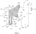
- Fig. 3 is a schematic view of the sealing device 1 and an attachment space S to which the sealing device 1 is attached taken from a cross section along an axis x1 to illustrate a difference in shape between the sealing device 1 and the attachment space S.
- the sealing device 1 and the attachment space S to which the sealing device 1 is attached overlap in the cross section along the axis x1 to schematically illustrate a difference in shape and size between the sealing device 1 and the attachment space S.
- a length of the elastic body part 20 including the lip portion 21, the seal lip portion 22, the outer peripheral portion 24, and the base portion 25 is longer than a length of the attachment space S in a direction of the axis x1.
- the outer peripheral portion 24 is a portion covering the reinforcing ring 10 from the outer periphery side c.
- the outer peripheral portion 24 has an outer-peripheral outer side end 24a, an end portion on the outer side a, that is joined to the lip portion 21.
- the outer peripheral portion 24 is formed such that an outer-peripheral inner side end 24b, an end portion on the inner side b, covers the reinforcing-ring inner side end 11 of the tubular portion 14.
- the outer peripheral portion 24 has an edge (a corner) formed on the outer periphery side c in the vicinity of the outer-peripheral inner side end 24b.
- the outer-peripheral inner side end 24b is defined by an annular surface facing the inner side b and an outer peripheral surface portion 24d that is a tubular surface facing the outer periphery side c.
- the base portion 25 covers the tubular portion 14 of the reinforcing ring 10 from the inner periphery side d.
- An end portion on the outer side a of the base portion 25 is joined to the lip portion 21.
- the base portion 25 is formed such that the inner peripheral portion 25a on the inner periphery side d covers the tubular-portion inner peripheral surface 14a of the tubular portion 14 from the inner periphery side d.
- the inner peripheral portion 25a of the base portion 25 is formed annularly around the axis x.
- the lip portion 21 is disposed so as to cover the flange 15 of the reinforcing ring 10 from the outer side a.
- the lip portion 21 is formed annularly around the axis x.
- a lip body 211, the seal lip portion 22, and the secondary lip portion 23 are disposed in the lip portion 21, a lip body 211, the seal lip portion 22, and the secondary lip portion 23 are disposed.
- the lip body 211 is formed so as to extend from the outer peripheral portion 24 and the base portion 25 of the elastic body part 20 toward the outer side a.
- the lip body 211 is, for example, formed such that an outer peripheral surface portion 21a, a surface on the outer periphery side c, is flush with the outer peripheral surface portion 24d of the outer peripheral portion 24.
- the lip body 211 is formed such that a surface on the outer side a of the lip body is parallel to or substantially parallel to a surface on the outer side a of the flange 15.
- the elastic body part includes the seal lip portion 22 and the secondary lip portion 23 on the inner periphery side d of the lip body 211.
- An inner peripheral surface portion 21b is formed between the seal lip portion 22 and the secondary lip portion 23 on the inner periphery side d of the lip body 211.
- the secondary lip portion 23 is formed so as to extend from an end portion on the inner periphery side d of the lip body 211 to the inner side b in the direction of the axis.
- the seal lip portion 22 projects diagonally from the end portion on the inner periphery side d of the lip body 211 toward the outer side a and the inner periphery side d.
- the seal lip portion 22 is, for example, a portion that increases in diameter as progress toward the inner side b (that decreases in diameter as progress toward the outer side a) in the direction of the axis x.
- An extent to which the seal lip portion 22 increases in diameter is not particularly limited.
- the seal lip portion 22 is a conical cylindrical or substantially conical cylindrical portion centered about or substantially centered about the axis x.
- the seal lip portion 22 projects to the outer side a with respect to the reinforcing-ring outer side end 12 and the flange 15.
- a seal-lip distal end 22a that is an end portion on the outer side a of the seal lip portion 22 is positioned on the outer side a with respect to the reinforcing-ring outer side end 12 and the flange 15 in the direction of the axis x.
- the elastic body part 20 of the sealing device 1 may be formed so as to increase in diameter as progress from the lip body 211 toward the seal-lip distal end 22a.
- An extent to which the elastic body part 20 of the sealing device 1 increases or decreases in diameter as progress from the lip body 211 toward the seal-lip distal end 22a may be constant or may vary place by place.
- the seal-lip distal end 22a is thinner than a seal-lip root 22b that is a portion joined to the lip body 211.
- the seal lip portion 22 may increase in thickness as progress from the seal-lip root 22b toward the seal-lip distal end 22a, for example.
- the seal lip portion 22 projects in a direction of the outer side a that is a direction, indicated by an arrow O1 in Fig. 3 , in which the sealing device comes off in a sealing structure where the sealing device 1 is attached.
- the seal-lip distal end 22a of the seal lip portion 22 projects to the outer side a with respect to the reinforcing ring 10 and the surface on the outer side a of the lip body 211 in a direction of an axis x1.
- the seal lip portion 22 projects to the inner periphery side d with respect to the reinforcing ring 10 and the lip body 211 in the radial direction.
- the seal lip portion 22 has a length and an outer peripheral surface so as to be in contact with an outer-side sealing surface 102a, a sealing surface on the outer side a, with a predetermined interference in a usage state described later.
- the length of the seal lip portion 22 is a width in a direction of extension (a direction of projection, the direction of the outer side a in Fig. 3 ) of the seal lip portion 22.
- the secondary lip portion 23 projects diagonally from a place on the inner side b of the end portion on the inner periphery side d of the lip body 211 toward the inner side b and the inner periphery side d.
- the secondary lip portion 23 is a portion that decreases in diameter as progress toward the inner side b in the direction of the axis x.
- the secondary lip portion 23 is a conical cylindrical or substantially conical cylindrical portion centered about or substantially centered about the axis x.
- the secondary lip portion 23 projects to the inner side b with respect to the reinforcing-ring inner peripheral end 16 on the inner side b of the flange 15.
- a secondary-lip distal end 23a is an end portion on the inner side b of the secondary lip portion 23.
- the secondary-lip distal end 23a is positioned on the inner side b with respect to the lip portion 21 and the flange 15 in the direction of the axis x.
- the secondary-lip distal end 23a is thinner than a secondary-lip root 23b that is a portion joined to the base portion 25.
- the secondary lip portion 23 decreases in thickness as progress from the secondary-lip root 23b toward the secondary-lip distal end 23a.
- the secondary lip portion 23 has a length so as to be in contact with a pipe end portion 122 on the outer side a of a pipe 120, a sealing surface on the inner side b, with a predetermined interference in the usage state described later.
- the secondary lip portion 23 is short in an amount of projection (a length of a projecting part) in the direction of the axis x as compared to the seal lip portion 22.
- the secondary lip portion 23 is also short in a dimension in the radial direction as compared to the seal lip portion 22. In other words, a total volume of the secondary lip portion 23 formed into a conical cylinder or a substantially conical cylinder is small as compared to that of the seal lip portion 22.
- the elastic body part 20 may not cover the flange inner side surface 15a on the inner side b of the flange 15.
- the elastic body part 20 may be flush with the flange inner side surface 15a in the direction of the axis x.
- the elastic body part 20 may not be flush with the flange inner side surface 15a in the direction of the axis x.
- the elastic body part 20 may cover the flange inner side surface 15a.
- the elastic body part 20 is formed such that the secondary-lip distal end 23a is positioned on the inner side b with respect to a part of the elastic body part 20 covering the flange inner side surface 15a in the direction of the axis x.
- Examples of the elastic body of the elastic body part 20 include various rubber materials.
- the various rubber materials are, for example, synthetic rubber such as nitrile rubber (NBR), hydrogenated nitrile rubber (H-NBR), acrylic rubber (ACM), and fluororubber (FKM).
- the reinforcing ring 10 is manufactured by press working or forging, for example.
- the elastic body part 20 is molded with a mold by cross-linking (vulcanization). During the cross-linking, the reinforcing ring 10 is placed in the mold.
- the elastic body part 20 is bonded to the reinforcing ring 10 by cross-linking bonding, and the elastic body part 20 is integrally molded with the reinforcing ring 10.
- Fig. 4 is a cross-sectional view illustrating the sealing device 1 in a usage state.
- the sealing device 1 gets into the usage state when the sealing device is attached to an attachment space S, an annular space.
- the attachment space S is an annular or substantially annular space that is formed around an axis x1 by a plurality of members.
- the attachment space S is, for example, formed by a housing 110 and the pipe 120, a cylindrical member.
- the housing 110 has a through-hole 111
- the pipe 120 has a through-hole 121 communicating with the through-hole 111 of the housing 110.
- the pipe 120 has the pipe end portion 122, a pipe inner peripheral surface 123, and a pipe surface 124.
- the pipe surface 124 is annular around the axis x1 and is exposed to the outer periphery side c.
- the pipe end portion 122 is annular in the radial direction.
- the pipe inner peripheral surface 123 faces the inner periphery side d and is formed around the axis x1.
- a space is formed between the housing 110 and the pipe 120 to only allow the sealing device 1 to be interposed between the members.
- the housing 110 is disposed such that a housing surface 112a of the housing faces the pipe end portion 122 of the pipe 120.
- the housing 110 is configured such that the through-hole 111 of the housing is coaxial or substantially coaxial with respect to the through-hole 121 of the pipe 120.
- the housing surface 112a is an annular flat surface facing the pipe end portion 122 of the pipe 120 in the direction of the axis x1.
- the housing surface 112a is an outer-side sealing surface.
- the attachment space S is an annular space defined by the above-described housing surface 112a and the pipe end portion 122 and the pipe inner peripheral surface 123 of the pipe 120.
- the sealing device 1 in the attachment space S seals the through-tube 130 formed by a through-hole 101 and the through-hole 111.
- the inner peripheral surface portion 21b of the lip portion 21 of the sealing device 1 faces the through-tube 130.
- pressure internal pressure P1 is exerted from the inner periphery side d toward the outer periphery side c.
- the sealing device 1 is attached to the pipe end portion 122 of the pipe 120 coaxially or substantially coaxially with respect to the through-tube 130.
- the axis x of the sealing device 1 illustrated in Fig. 2 and the axis x1 coincide with or slightly diverge from each other.
- the inner peripheral portion 25a of the base portion 25 centered about and formed annularly around the axis x1 at the inner periphery side d of the tubular-portion inner peripheral surface 14a is in contact with the pipe surface 124, an outer side surface of the pipe 120, across a range indicated by an arrow O2 in the direction of the axis x.
- the tubular-portion inner peripheral surface 14a formed in the sealing device 1 allows the sealing device to be put into contact with the pipe surface 124, an outer peripheral portion of the pipe 120, and movement of the sealing device in the radial direction is restricted by an inside diameter of the tubular-portion inner peripheral surface 14a. This configuration enables the sealing device to be positioned in the radial direction.
- the flange inner side surface 15a is in contact with the pipe end portion 122 of the pipe 120.
- the secondary lip portion 23 is pressed by the pipe end portion 122 of the pipe 120 and is in contact with the pipe end portion 122 with a predetermined interference or squeeze.
- the flange inner side surface 15a of the reinforcing ring 10 and the secondary lip portion 23 of the elastic body part 20 are disposed.
- the members formed in this way allows the sealing device 1 to be put into contact with the pipe end portion 122, a surface on the outer side a of the pipe 120, and movement of the sealing device in the direction of the axis x is restricted. This configuration enables the sealing device to be positioned in the direction of the axis x.
- Fig. 5 is a cross-sectional view of a sealing device 2 according to a reference example taken along an axis x.
- Fig. 6 is a cross-sectional view of the sealing device 2 according to the reference example taken along the axis x.
- a reinforcing ring 214 does not include a tubular portion 14 and a flange 15 unlike the sealing device 1.
- an elastic body part 220 does not include a lip portion 21 projecting from a reinforcing ring 10 toward the outer side a in the direction of the axis x unlike the sealing device 1.
- the reinforcing ring 214 does not include the tubular portion 14 and the flange 15 unlike the sealing device 1. This necessitates forming a groove 228 with an increased diameter in the inner periphery side d of a pipe 320 to which the sealing device 2 is attached to hold the sealing device 2 from the outer periphery side c.
- a sealing device 2B is configured in a similar way to the sealing device 2.
- an inner peripheral wall part 328b is inevitably thin in thickness depending on a dimension and a thickness of the pipe 320 in the radial direction, and this makes it difficult to provide a groove 328.
- the sealing device 1 is designed to be positioned in the radial direction by the tubular-portion inner peripheral surface 14a of the reinforcing ring 10 and the inner peripheral portion 25a of the base portion 25 of the elastic body part 20 and is designed to be positioned in the direction of the axis x by the flange inner side surface 15a and the secondary lip portion 23.
- the sealing device 1 can be, for example, attached to even a pipe 120 that is thin in thickness and makes it difficult to form a groove without formation of a groove in the inner periphery side d of the pipe.
- the sealing device 1 can possess improved attachability to a component to which the sealing device is applied.
- the seal lip portion 22 and the secondary lip portion 23 of the lip portion 21 are formed from the elastic body part 20, which is a single elastic body.
- the secondary lip portion 23 projecting to the inner side b in the direction of the axis x is smaller than the seal lip portion 22 projecting to the outer side a in the direction of the axis x.
- the secondary lip portion 23 is low in rigidity and can readily deform compared to the seal lip portion 22.
- the secondary lip portion 23 deforms positively when being compressed by an external force or when receiving the internal pressure P1 from the through-tube 130 toward the outer periphery side c.
- the secondary lip portion 23 deforms positively and the flange inner side surface 15a is thereby put into contact with the pipe end portion 122 of the pipe 120. This enables the sealing device 1 to be positioned in the direction of the axis x.
- the lip portion 21 configured as described above enables the sealing device 1 to inhibit posture deformation caused by the internal pressure P1 and thus provide stable sealing performance.
- the lip portion 21 configured as described above enables the sealing device 1 to offset a difference (a variation) in a size of the attachment space S by the seal lip portion 22 having a large size.
- the lip portion 21 configured as described above enables the sealing device 1 to inhibit the tubular-portion inner peripheral surface 14a and the inner peripheral portion 25a from moving to the outer side a in the direction of the axis x and being detached from the pipe surface 124 of the pipe 120. This prevents the sealing device 1 from coming off.
- the sealing device 1 according to the first embodiment of the present invention can possess improved attachability to a component such as the pipe 120 to which the sealing device is applied.
- Fig. 7 is a cross-sectional view illustrating the sealing device 1 in a modification example of a usage state taken along an axis.
- the sealing device 1 is attached such that the inner peripheral portion 25a of the base portion 25 of the elastic body part 20 is in contact with a pipe inner peripheral surface 123B of a pipe 120B and the inner peripheral surface portion 21b of the lip portion 21 faces the outer periphery side c of the attachment space S.
- the sealing device 1 can also be applied to a component to seal the component against pressure (external pressure P2) from the outer periphery side c.
- sealing device 1C according to a second embodiment of the present invention will be described.
- components of the sealing device 1C that are identical or similar in function to those of the sealing device 1 according to the first embodiment described above are assigned the same reference signs, and descriptions thereof are omitted. Only components that differ between the sealing devices will be described.
- Fig. 8 is a bottom view for illustrating a schematic configuration of the sealing device 1C according to the second embodiment of the present invention.
- Fig. 9 is a perspective cross-sectional view of the sealing device 1C taken from cross section B-B along an axis x.
- protrusions 25bC each projecting toward the inner periphery side d may be formed on an inner peripheral portion 25aC of a base portion 25C.
- the inner peripheral portion 25aC faces the inner periphery side d and covers a tubular-portion inner peripheral surface 14a from the inner periphery side d.
- the protrusions 25bC are in contact with a pipe surface of a pipe.
- the protrusions 25bC position the sealing device relative to the pipe surface in the radial direction. With the protrusions 25bC formed on the inner peripheral portion 25aC, the sealing device 1C is kept from coming off in the usage state.
- the other components of the sealing device 1C are similar to those of the sealing device 1 described above.
- the sealing device 1C according to the second embodiment can possess improved attachability to a component to which the sealing device is applied.
- the present invention is not limited to the above-described embodiments of the present invention, and includes any modes falling within the scope of the concept and claims of the present invention.
- Respective configurations may be appropriately selectively combined to solve at least part of the above-described problems and achieve at least part of the above-described effects.
- the shape, material, arrangement, size and the like of each component can be appropriately changed according to a specific use mode of the present invention.
Landscapes
- Engineering & Computer Science (AREA)
- General Engineering & Computer Science (AREA)
- Mechanical Engineering (AREA)
- Gasket Seals (AREA)
- Burglar Alarm Systems (AREA)
Abstract
Description
- The present invention relates to a sealing device.
- Conventionally, it is known that a gasket acts as a sealing device that is attached to an annular space like an annular groove formed between a plurality of members, such as a housing and a cover, placed face-to-face and immobilized relative to each other, to seal the annular space. Such a gasket and a plurality of members forming an annular space to which the gasket is attached make up a sealing structure. The gasket as described above including a tubular reinforcing ring formed annularly around an axis and extending in a direction of the axis and an elastic body part formed from an elastic body that is attached to the reinforcing ring is disclosed. In the gasket, the elastic body part includes a pair of lip portions each extending along the axis from both end portions of the reinforcing ring in the direction of the axis (for example, see Patent Literature 1).
- In recent years, in response to reductions in size or weight of a component to which the gasket is applied, a cross section of the gasket has been made smaller due to downsizing of the gasket and the component to which the gasket is applied has been developed to be made thinner or to be made of resin. The smaller cross section of the gasket and the development of the component to which the gasket is applied being made thinner or being made of resin decrease a size of the annular space to which the gasket is attached and increase a degree of relative variation in the size of the space caused by manufacturing. As a result, it is conceivable that a gasket cannot provide intended sealing performance because of the variation in the size of the annular space to which the gasket is attached and thus techniques have been disclosed to resolve such a problem (for example, see Patent Literature 2).
-
- Patent Literature 1:
Japanese Utility Model Laid-Open No. 6-32834 - Patent Literature 2: International Publication No.
WO 2015/137491 - If the component to which the gasket is applied is a pipe that constitutes, for example, a hydraulic passage, the gasket receives pressure (internal pressure) from the hydraulic passage on an inner periphery side of the gasket. Thus, in general, the gasket for the pipe of the hydraulic passage is held in an annular groove formed in an inner periphery side of the pipe, as disclosed in the technique of
Patent Literature 1, to prevent the gasket from being displaced by the internal pressure in a radial direction perpendicular to the direction of the axis. - Unfortunately, the conventional gasket as disclosed in
Patent Literature 1 necessitates forming a groove in the inner periphery side of the pipe. Hence, the conventional gasket cannot be applied to a pipe that is, for example, thin in thickness and makes it difficult to form a groove. - In view of the problems described above, it is an object of the present invention to provide a sealing device that can possess improved attachability to a component to which the sealing device is applied.
- A sealing device according to the present invention, accomplished to attain the object described above, is for sealing an annular space formed by a plurality of members, the sealing device including: a reinforcing ring formed annularly around an axis; and an elastic body part that is formed from an elastic body attached to the reinforcing ring and that is formed annularly around the axis, the reinforcing ring including: a tubular portion having a cylindrical shape around the axis; and a flange projecting annularly from an outer end portion of the tubular portion to an inner periphery side, wherein the elastic body part includes a lip portion that is an annular portion covering the flange from an outer side, projecting from the flange toward the outer side in a direction of the axis, and projecting toward the inner periphery side in a radial direction, the lip portion including: a seal lip portion that is an annular portion projecting toward the outer side in the direction of the axis; and a secondary lip portion that is an annular portion projecting toward an inner side in the direction of the axis.
- In the sealing device according to one aspect of the present invention, the tubular portion has a tubular-portion inner peripheral surface on the inner periphery side, the flange has a flange inner side surface on the inner side, the tubular-portion inner peripheral surface enables the sealing device to be positioned relative to the plurality of members in the radial direction, and the flange inner side surface enables the sealing device to be positioned relative to the plurality of members in the direction of the axis.
- In the sealing device according to one aspect of the present invention, the elastic body part includes an inner peripheral portion covering the tubular-portion inner peripheral surface from the inner periphery side.
- In the sealing device according to one aspect of the present invention, the plurality of members include at least a cylindrical member, the tubular-portion inner peripheral surface enables the sealing device to be positioned in the radial direction by allowing the sealing device to be in contact with an outer peripheral portion included in the cylindrical member, and the flange inner side surface enables the sealing device to be positioned in the direction of the axis by allowing the sealing device to be in contact with an outer side surface formed on the cylindrical member.
- In the sealing device according to one aspect of the present invention, the seal lip portion projects to the outer side with respect to the flange in the direction of the axis, and the secondary lip portion projects to the inner side with respect to the flange in the direction of the axis.
- In the sealing device according to one aspect of the present invention, a length of the seal lip portion in the direction of the axis is greater than a length of the secondary lip portion in the direction of the axis.
- The sealing device according to the present invention can possess improved attachability to a component to which the sealing device is applied.
-
- [
Fig. 1 ] A bottom view for illustrating a schematic configuration of a sealing device according to a first embodiment of the present invention. - [
Fig. 2 ] A cross-sectional view of the sealing device illustrated inFig. 1 taken from cross section A-A along an axis. - [
Fig. 3 ] A schematic view of the sealing device illustrated inFig. 1 and an attachment space to which the sealing device is attached taken from a cross section along an axis to illustrate a difference in shape between the sealing device and the attachment space. - [
Fig. 4 ] A cross-sectional view illustrating the sealing device illustrated inFig. 1 in a usage state. - [
Fig. 5 ] A cross-sectional view illustrating a sealing device according to a reference example in a usage state taken along an axis. - [
Fig. 6 ] A cross-sectional view illustrating the sealing device according to the reference example illustrated inFig. 5 in another usage state taken along an axis. - [
Fig. 7 ] A cross-sectional view illustrating the sealing device illustrated inFig. 1 in a modification example of a usage state taken along an axis. - [
Fig. 8 ] A bottom view for illustrating a schematic configuration of a sealing device according to a second embodiment of the present invention. - [
Fig. 9 ] A perspective cross-sectional view of the sealing device illustrated inFig. 8 taken from cross section B-B along an axis. - Hereinafter, embodiments of the present invention will be described with reference to the drawings.
-
Fig. 1 is a bottom view for illustrating a schematic configuration of asealing device 1 according to a first embodiment of the present invention.Fig. 2 is a cross-sectional view of thesealing device 1 taken from cross section A-A along an axis x. - Hereinafter, a direction directed by an arrow a in a direction of the axis x (one side in the direction of the axis, see
Fig. 2 ) represents an outer side, and a direction directed by an arrow b in the direction of the axis x (another side in the direction of the axis, seeFig. 2 ) represents an inner side, for convenience of explanation. In a direction perpendicular to the axis x (hereinafter also referred to as a "radial direction"), a direction away from the axis x (a direction directed by an arrow c inFig. 2 ) represents an outer periphery side, and a direction approaching the axis x (a direction directed by an arrow d inFig. 2 ) represents an inner periphery side. - As illustrated in
Figs. 1 and2 , thesealing device 1 according to the first embodiment of the present invention includes a reinforcingring 10 formed annularly around the axis x and anelastic body part 20 that is formed from an elastic body attached to the reinforcingring 10 and that is formed annularly around the axis x. The reinforcingring 10 includes atubular portion 14 having a cylindrical shape around the axis x and aflange 15 projecting annularly from an outer end portion of thetubular portion 14 to an inner periphery side d. Theelastic body part 20 includes alip portion 21 that is an annular portion covering theflange 15 from an outer side a, projecting from theflange 15 toward the outer side a in the direction of the axis x, and projecting toward the inner periphery side d in the radial direction. Thelip portion 21 includes aseal lip portion 22 that is an annular portion projecting toward the outer side a in the direction of the axis x and asecondary lip portion 23 that is an annular portion projecting toward an inner side b in the direction of the axis x. Hereinafter, thesealing device 1 will be described in detail. - As illustrated in
Fig. 2 , thereinforcing ring 10 is a tubular or substantially tubular member extending along the axis x. The reinforcingring 10 is, for example, a cylindrical or substantially cylindrical member centered about or substantially centered about the axis x. The reinforcingring 10, as described above, includes thetubular portion 14 and theflange 15. Thetubular portion 14 has a cylindrical or substantially cylindrical surface formed around the axis x. Thetubular portion 14 has a reinforcing-ringinner side end 11 that is formed on an end portion on the inner side b and a reinforcing-ringouter side end 12 that is an end portion on the outer side a. Thetubular portion 14 has a tubular-portion innerperipheral surface 14a that is a surface on the inner periphery side d. - The
flange 15 annularly projects toward the inner periphery side d from the reinforcing-ringouter side end 12, an end portion on the outer side a of thetubular portion 14. Theflange 15 has a reinforcing-ring innerperipheral end 16 that is an end portion on the inner periphery side d. Theflange 15 has a flangeinner side surface 15a that is a surface on the inner side d. - The reinforcing
ring 10 is a part used to reinforce theelastic body part 20. Thetubular portion 14 and theflange 15 of the reinforcingring 10 are formed, for example, by bending a metal material. The metal material used in the reinforcingring 10 is, for example, stainless steel or SPCC (a cold rolled steel sheet). If the reinforcingring 10 is made of a resin material, the resin material used in the reinforcing ring is, for example, nylon 66 (PA66) or a polyphenylene sulfide (PPS) resin. - The
elastic body part 20 is formed so as to cover the reinforcingring 10. Theelastic body part 20, as described above, has thelip portion 21, as well as theseal lip portion 22, thesecondary lip portion 23, an outerperipheral portion 24, and abase portion 25. The outerperipheral portion 24 covers a surface on an outer periphery side c of thetubular portion 14. Thetubular portion 14 is formed annularly in the reinforcingring 10. Thebase portion 25 covers a part at the inner periphery side d of the outerperipheral portion 24, i.e., a surface on the inner periphery side d of thetubular portion 14. A portion of thebase portion 25 facing the inner periphery side d is an innerperipheral portion 25a. The innerperipheral portion 25a covers the tubular-portion innerperipheral surface 14a from the inner periphery side d. -
Fig. 3 is a schematic view of thesealing device 1 and an attachment space S to which thesealing device 1 is attached taken from a cross section along an axis x1 to illustrate a difference in shape between the sealingdevice 1 and the attachment space S. InFig. 3 , thesealing device 1 and the attachment space S to which thesealing device 1 is attached overlap in the cross section along the axis x1 to schematically illustrate a difference in shape and size between the sealingdevice 1 and the attachment space S. As illustrated inFig. 3 , regarding thesealing device 1, a length of theelastic body part 20 including thelip portion 21, theseal lip portion 22, the outerperipheral portion 24, and thebase portion 25 is longer than a length of the attachment space S in a direction of the axis x1. - As illustrated in
Fig. 2 , the outerperipheral portion 24 is a portion covering the reinforcingring 10 from the outer periphery side c. The outerperipheral portion 24 has an outer-peripheralouter side end 24a, an end portion on the outer side a, that is joined to thelip portion 21. The outerperipheral portion 24 is formed such that an outer-peripheralinner side end 24b, an end portion on the inner side b, covers the reinforcing-ring inner side end 11 of thetubular portion 14. The outerperipheral portion 24 has an edge (a corner) formed on the outer periphery side c in the vicinity of the outer-peripheralinner side end 24b. The outer-peripheralinner side end 24b is defined by an annular surface facing the inner side b and an outerperipheral surface portion 24d that is a tubular surface facing the outer periphery side c. - As illustrated in
Fig. 2 , thebase portion 25 covers thetubular portion 14 of the reinforcingring 10 from the inner periphery side d. An end portion on the outer side a of thebase portion 25 is joined to thelip portion 21. Thebase portion 25 is formed such that the innerperipheral portion 25a on the inner periphery side d covers the tubular-portion innerperipheral surface 14a of thetubular portion 14 from the inner periphery side d. In other words, in thesealing device 1, the innerperipheral portion 25a of thebase portion 25 is formed annularly around the axis x. - The
lip portion 21 is disposed so as to cover theflange 15 of the reinforcingring 10 from the outer side a. Thelip portion 21 is formed annularly around the axis x. In thelip portion 21, alip body 211, theseal lip portion 22, and thesecondary lip portion 23 are disposed. - The
lip body 211 is formed so as to extend from the outerperipheral portion 24 and thebase portion 25 of theelastic body part 20 toward the outer side a. Thelip body 211 is, for example, formed such that an outerperipheral surface portion 21a, a surface on the outer periphery side c, is flush with the outerperipheral surface portion 24d of the outerperipheral portion 24. Thelip body 211 is formed such that a surface on the outer side a of the lip body is parallel to or substantially parallel to a surface on the outer side a of theflange 15. The elastic body part includes theseal lip portion 22 and thesecondary lip portion 23 on the inner periphery side d of thelip body 211. An innerperipheral surface portion 21b is formed between theseal lip portion 22 and thesecondary lip portion 23 on the inner periphery side d of thelip body 211. Thesecondary lip portion 23 is formed so as to extend from an end portion on the inner periphery side d of thelip body 211 to the inner side b in the direction of the axis. - The
seal lip portion 22 projects diagonally from the end portion on the inner periphery side d of thelip body 211 toward the outer side a and the inner periphery side d. Theseal lip portion 22 is, for example, a portion that increases in diameter as progress toward the inner side b (that decreases in diameter as progress toward the outer side a) in the direction of the axis x. An extent to which theseal lip portion 22 increases in diameter is not particularly limited. Theseal lip portion 22 is a conical cylindrical or substantially conical cylindrical portion centered about or substantially centered about the axis x. Theseal lip portion 22 projects to the outer side a with respect to the reinforcing-ringouter side end 12 and theflange 15. A seal-lipdistal end 22a that is an end portion on the outer side a of theseal lip portion 22 is positioned on the outer side a with respect to the reinforcing-ringouter side end 12 and theflange 15 in the direction of the axis x. Theelastic body part 20 of thesealing device 1 may be formed so as to increase in diameter as progress from thelip body 211 toward the seal-lipdistal end 22a. An extent to which theelastic body part 20 of thesealing device 1 increases or decreases in diameter as progress from thelip body 211 toward the seal-lipdistal end 22a may be constant or may vary place by place. The seal-lipdistal end 22a is thinner than a seal-lip root 22b that is a portion joined to thelip body 211. Theseal lip portion 22 may increase in thickness as progress from the seal-lip root 22b toward the seal-lipdistal end 22a, for example. - The
seal lip portion 22 projects in a direction of the outer side a that is a direction, indicated by an arrow O1 inFig. 3 , in which the sealing device comes off in a sealing structure where thesealing device 1 is attached. The seal-lipdistal end 22a of theseal lip portion 22 projects to the outer side a with respect to the reinforcingring 10 and the surface on the outer side a of thelip body 211 in a direction of an axis x1. Theseal lip portion 22 projects to the inner periphery side d with respect to the reinforcingring 10 and thelip body 211 in the radial direction. In other words, theseal lip portion 22 has a length and an outer peripheral surface so as to be in contact with an outer-side sealing surface 102a, a sealing surface on the outer side a, with a predetermined interference in a usage state described later. Note that the length of theseal lip portion 22 is a width in a direction of extension (a direction of projection, the direction of the outer side a inFig. 3 ) of theseal lip portion 22. - As illustrated in
Fig. 2 , thesecondary lip portion 23, for example, projects diagonally from a place on the inner side b of the end portion on the inner periphery side d of thelip body 211 toward the inner side b and the inner periphery side d. Specifically, thesecondary lip portion 23 is a portion that decreases in diameter as progress toward the inner side b in the direction of the axis x. Thesecondary lip portion 23 is a conical cylindrical or substantially conical cylindrical portion centered about or substantially centered about the axis x. Thesecondary lip portion 23 projects to the inner side b with respect to the reinforcing-ring innerperipheral end 16 on the inner side b of theflange 15. A secondary-lipdistal end 23a is an end portion on the inner side b of thesecondary lip portion 23. The secondary-lipdistal end 23a is positioned on the inner side b with respect to thelip portion 21 and theflange 15 in the direction of the axis x. The secondary-lipdistal end 23a is thinner than a secondary-lip root 23b that is a portion joined to thebase portion 25. Thesecondary lip portion 23, for example, extends from thelip body 211 toward the inner side b and the inner periphery side d. Thesecondary lip portion 23 decreases in thickness as progress from the secondary-lip root 23b toward the secondary-lipdistal end 23a. Thesecondary lip portion 23 has a length so as to be in contact with apipe end portion 122 on the outer side a of apipe 120, a sealing surface on the inner side b, with a predetermined interference in the usage state described later. Thesecondary lip portion 23 is short in an amount of projection (a length of a projecting part) in the direction of the axis x as compared to theseal lip portion 22. Thesecondary lip portion 23 is also short in a dimension in the radial direction as compared to theseal lip portion 22. In other words, a total volume of thesecondary lip portion 23 formed into a conical cylinder or a substantially conical cylinder is small as compared to that of theseal lip portion 22. - As illustrated in
Fig. 2 , theelastic body part 20 may not cover the flangeinner side surface 15a on the inner side b of theflange 15. Theelastic body part 20 may be flush with the flangeinner side surface 15a in the direction of the axis x. Theelastic body part 20 may not be flush with the flangeinner side surface 15a in the direction of the axis x. Theelastic body part 20 may cover the flangeinner side surface 15a. In this case, theelastic body part 20 is formed such that the secondary-lipdistal end 23a is positioned on the inner side b with respect to a part of theelastic body part 20 covering the flangeinner side surface 15a in the direction of the axis x. - Examples of the elastic body of the
elastic body part 20 include various rubber materials. The various rubber materials are, for example, synthetic rubber such as nitrile rubber (NBR), hydrogenated nitrile rubber (H-NBR), acrylic rubber (ACM), and fluororubber (FKM). - The reinforcing
ring 10 is manufactured by press working or forging, for example. Theelastic body part 20 is molded with a mold by cross-linking (vulcanization). During the cross-linking, the reinforcingring 10 is placed in the mold. Theelastic body part 20 is bonded to the reinforcingring 10 by cross-linking bonding, and theelastic body part 20 is integrally molded with the reinforcingring 10. - Thereafter, the
sealing device 1 in the usage state described above will be described. -
Fig. 4 is a cross-sectional view illustrating thesealing device 1 in a usage state. As illustrated inFig. 4 , thesealing device 1 gets into the usage state when the sealing device is attached to an attachment space S, an annular space. The attachment space S is an annular or substantially annular space that is formed around an axis x1 by a plurality of members. The attachment space S is, for example, formed by ahousing 110 and thepipe 120, a cylindrical member. Thehousing 110 has a through-hole 111, and thepipe 120 has a through-hole 121 communicating with the through-hole 111 of thehousing 110. Thepipe 120 has thepipe end portion 122, a pipe innerperipheral surface 123, and apipe surface 124. Thepipe surface 124 is annular around the axis x1 and is exposed to the outer periphery side c. Thepipe end portion 122 is annular in the radial direction. The pipe innerperipheral surface 123 faces the inner periphery side d and is formed around the axis x1. In the attachment space S, a space is formed between thehousing 110 and thepipe 120 to only allow thesealing device 1 to be interposed between the members. - The
housing 110 is disposed such that ahousing surface 112a of the housing faces thepipe end portion 122 of thepipe 120. Thehousing 110 is configured such that the through-hole 111 of the housing is coaxial or substantially coaxial with respect to the through-hole 121 of thepipe 120. Thus, the through-hole 111 and the through-hole 121 communicate to form a single through-tube 130. Thehousing surface 112a is an annular flat surface facing thepipe end portion 122 of thepipe 120 in the direction of the axis x1. In thehousing 110, thehousing surface 112a is an outer-side sealing surface. The attachment space S is an annular space defined by the above-describedhousing surface 112a and thepipe end portion 122 and the pipe innerperipheral surface 123 of thepipe 120. Thesealing device 1 in the attachment space S seals the through-tube 130 formed by a through-hole 101 and the through-hole 111. In the attachment space S, the innerperipheral surface portion 21b of thelip portion 21 of thesealing device 1 faces the through-tube 130. In the through-tube 130, pressure (internal pressure P1) is exerted from the inner periphery side d toward the outer periphery side c. - In the usage state, the
sealing device 1 is attached to thepipe end portion 122 of thepipe 120 coaxially or substantially coaxially with respect to the through-tube 130. In other words, in the usage state, the axis x of thesealing device 1 illustrated inFig. 2 and the axis x1 coincide with or slightly diverge from each other. - As illustrated in
Figs. 3 and4 , the innerperipheral portion 25a of thebase portion 25 centered about and formed annularly around the axis x1 at the inner periphery side d of the tubular-portion innerperipheral surface 14a is in contact with thepipe surface 124, an outer side surface of thepipe 120, across a range indicated by an arrow O2 in the direction of the axis x. In other words, the tubular-portion innerperipheral surface 14a formed in thesealing device 1 allows the sealing device to be put into contact with thepipe surface 124, an outer peripheral portion of thepipe 120, and movement of the sealing device in the radial direction is restricted by an inside diameter of the tubular-portion innerperipheral surface 14a. This configuration enables the sealing device to be positioned in the radial direction. - The flange
inner side surface 15a is in contact with thepipe end portion 122 of thepipe 120. Thesecondary lip portion 23 is pressed by thepipe end portion 122 of thepipe 120 and is in contact with thepipe end portion 122 with a predetermined interference or squeeze. In other words, in thesealing device 1, the flangeinner side surface 15a of the reinforcingring 10 and thesecondary lip portion 23 of theelastic body part 20 are disposed. The members formed in this way allows thesealing device 1 to be put into contact with thepipe end portion 122, a surface on the outer side a of thepipe 120, and movement of the sealing device in the direction of the axis x is restricted. This configuration enables the sealing device to be positioned in the direction of the axis x. -
Fig. 5 is a cross-sectional view of asealing device 2 according to a reference example taken along an axis x.Fig. 6 is a cross-sectional view of thesealing device 2 according to the reference example taken along the axis x. - As illustrated in
Figs. 5 and 6 , in thesealing device 2 according to the reference example, a reinforcingring 214 does not include atubular portion 14 and aflange 15 unlike thesealing device 1. In thesealing device 2 according to the reference example, anelastic body part 220 does not include alip portion 21 projecting from a reinforcingring 10 toward the outer side a in the direction of the axis x unlike thesealing device 1. - In the
sealing device 2, the reinforcingring 214 does not include thetubular portion 14 and theflange 15 unlike thesealing device 1. This necessitates forming agroove 228 with an increased diameter in the inner periphery side d of apipe 320 to which thesealing device 2 is attached to hold thesealing device 2 from the outer periphery side c. - As illustrated in
Fig. 6 , a sealing device 2B is configured in a similar way to thesealing device 2. Thus, in some cases, an innerperipheral wall part 328b is inevitably thin in thickness depending on a dimension and a thickness of thepipe 320 in the radial direction, and this makes it difficult to provide agroove 328. - Meanwhile, as described above, the
sealing device 1 is designed to be positioned in the radial direction by the tubular-portion innerperipheral surface 14a of the reinforcingring 10 and the innerperipheral portion 25a of thebase portion 25 of theelastic body part 20 and is designed to be positioned in the direction of the axis x by the flangeinner side surface 15a and thesecondary lip portion 23. As a result, thesealing device 1 can be, for example, attached to even apipe 120 that is thin in thickness and makes it difficult to form a groove without formation of a groove in the inner periphery side d of the pipe. - Thus, the
sealing device 1 can possess improved attachability to a component to which the sealing device is applied. - In the
sealing device 1, theseal lip portion 22 and thesecondary lip portion 23 of thelip portion 21 are formed from theelastic body part 20, which is a single elastic body. Here, thesecondary lip portion 23 projecting to the inner side b in the direction of the axis x is smaller than theseal lip portion 22 projecting to the outer side a in the direction of the axis x. As a result, in thelip portion 21, thesecondary lip portion 23 is low in rigidity and can readily deform compared to theseal lip portion 22. In other words, thesecondary lip portion 23 deforms positively when being compressed by an external force or when receiving the internal pressure P1 from the through-tube 130 toward the outer periphery side c. In this way, thesecondary lip portion 23 deforms positively and the flangeinner side surface 15a is thereby put into contact with thepipe end portion 122 of thepipe 120. This enables thesealing device 1 to be positioned in the direction of the axis x. - The
lip portion 21 configured as described above enables thesealing device 1 to inhibit posture deformation caused by the internal pressure P1 and thus provide stable sealing performance. Thelip portion 21 configured as described above enables thesealing device 1 to offset a difference (a variation) in a size of the attachment space S by theseal lip portion 22 having a large size. Further, thelip portion 21 configured as described above enables thesealing device 1 to inhibit the tubular-portion innerperipheral surface 14a and the innerperipheral portion 25a from moving to the outer side a in the direction of the axis x and being detached from thepipe surface 124 of thepipe 120. This prevents thesealing device 1 from coming off. - As described above, the
sealing device 1 according to the first embodiment of the present invention can possess improved attachability to a component such as thepipe 120 to which the sealing device is applied. -
Fig. 7 is a cross-sectional view illustrating thesealing device 1 in a modification example of a usage state taken along an axis. Unlike the sealing device in an example of the usage state illustrated inFig. 3 , thesealing device 1, as illustrated inFig. 7 , is attached such that the innerperipheral portion 25a of thebase portion 25 of theelastic body part 20 is in contact with a pipe innerperipheral surface 123B of apipe 120B and the innerperipheral surface portion 21b of thelip portion 21 faces the outer periphery side c of the attachment space S. Being attached in this way, thesealing device 1 can also be applied to a component to seal the component against pressure (external pressure P2) from the outer periphery side c. - Thereafter, a
sealing device 1C according to a second embodiment of the present invention will be described. Hereinafter, components of thesealing device 1C that are identical or similar in function to those of thesealing device 1 according to the first embodiment described above are assigned the same reference signs, and descriptions thereof are omitted. Only components that differ between the sealing devices will be described. -
Fig. 8 is a bottom view for illustrating a schematic configuration of thesealing device 1C according to the second embodiment of the present invention.Fig. 9 is a perspective cross-sectional view of thesealing device 1C taken from cross section B-B along an axis x. - As illustrated in
Figs. 8 and 9 , in thesealing device 1C, protrusions 25bC each projecting toward the inner periphery side d may be formed on an inner peripheral portion 25aC of abase portion 25C. The inner peripheral portion 25aC faces the inner periphery side d and covers a tubular-portion innerperipheral surface 14a from the inner periphery side d. When thesealing device 1C is in a usage state, the protrusions 25bC are in contact with a pipe surface of a pipe. The protrusions 25bC position the sealing device relative to the pipe surface in the radial direction. With the protrusions 25bC formed on the inner peripheral portion 25aC, thesealing device 1C is kept from coming off in the usage state. The other components of thesealing device 1C are similar to those of thesealing device 1 described above. - In a similar way to the
sealing device 1 described above, thesealing device 1C according to the second embodiment can possess improved attachability to a component to which the sealing device is applied. - Although the embodiments of the present invention have been described above, the present invention is not limited to the above-described embodiments of the present invention, and includes any modes falling within the scope of the concept and claims of the present invention. Respective configurations may be appropriately selectively combined to solve at least part of the above-described problems and achieve at least part of the above-described effects. For example, in the above-described embodiments, the shape, material, arrangement, size and the like of each component can be appropriately changed according to a specific use mode of the present invention.
-
- 1 sealing device,
- 10 reinforcing ring,
- 11 reinforcing-ring inner side end,
- 12 reinforcing-ring outer side end,
- 14 tubular portion,
- 14a tubular-portion inner peripheral surface,
- 15 flange,
- 15a flange inner side surface,
- 16 reinforcing-ring inner peripheral end,
- 20 elastic body part,
- 21 lip portion,
- 21a outer peripheral surface portion,
- 21b inner peripheral surface portion,
- 22 seal lip portion,
- 22a seal-lip distal end,
- 22b seal-lip root,
- 23 secondary lip portion,
- 23a secondary-lip distal end,
- 23b secondary-lip root,
- 24 outer peripheral portion,
- 24a outer-peripheral outer side end,
- 24b outer-peripheral inner side end,
- 24d outer peripheral surface portion,
- 25, 25C base portion,
- 25a, 25aC inner peripheral portion,
- 25bC protrusion,
- 101 through-hole,
- 102a outer-side sealing surface,
- 110 housing,
- 111 through-hole,
- 112a housing surface,
- 120 pipe,
- 121 through-hole,
- 122 pipe end portion,
- 123 pipe inner peripheral surface,
- 124 pipe surface,
- 130 through-tube
Claims (6)
- A sealing device for sealing an annular space formed by a plurality of members, the sealing device comprising:a reinforcing ring formed annularly around an axis; andan elastic body part that is formed from an elastic body attached to the reinforcing ring and that is formed annularly around the axis, the reinforcing ring including:a tubular portion having a cylindrical shape around the axis; anda flange projecting annularly from an outer end portion of the tubular portion to an inner periphery side,wherein the elastic body part includes a lip portion that is an annular portion covering the flange from an outer side, projecting from the flange toward the outer side in a direction of the axis, and projecting toward the inner periphery side in a radial direction, the lip portion including:a seal lip portion that is an annular portion projecting toward the outer side in the direction of the axis; anda secondary lip portion that is an annular portion projecting toward an inner side in the direction of the axis.
- The sealing device according to claim 1, wherein the tubular portion has a tubular-portion inner peripheral surface on the inner periphery side,wherein the flange has a flange inner side surface on the inner side,wherein the tubular-portion inner peripheral surface enables the sealing device to be positioned relative to the plurality of members in the radial direction, andwherein the flange inner side surface enables the sealing device to be positioned relative to the plurality of members in the direction of the axis.
- The sealing device according to claim 2, wherein the elastic body part includes an inner peripheral portion covering the tubular-portion inner peripheral surface from the inner periphery side.
- The sealing device according to claim 3, wherein the plurality of members include at least a cylindrical member,wherein the tubular-portion inner peripheral surface enables the sealing device to be positioned in the radial direction by allowing the sealing device to be in contact with an outer peripheral portion included in the cylindrical member, andwherein the flange inner side surface enables the sealing device to be positioned in the direction of the axis by allowing the sealing device to be in contact with an outer side surface formed on the cylindrical member.
- The sealing device according to any one of claims 1 to 4, wherein the seal lip portion projects to the outer side with respect to the flange in the direction of the axis, and
wherein the secondary lip portion projects to the inner side with respect to the flange in the direction of the axis. - The sealing device according to any one of claims 1 to 5, wherein a length of the seal lip portion in the direction of the axis is greater than a length of the secondary lip portion in the direction of the axis.
Applications Claiming Priority (2)
| Application Number | Priority Date | Filing Date | Title |
|---|---|---|---|
| JP2019135833 | 2019-07-24 | ||
| PCT/JP2020/022358 WO2021014798A1 (en) | 2019-07-24 | 2020-06-05 | Sealing device |
Publications (2)
| Publication Number | Publication Date |
|---|---|
| EP4006388A1 true EP4006388A1 (en) | 2022-06-01 |
| EP4006388A4 EP4006388A4 (en) | 2023-07-26 |
Family
ID=74193358
Family Applications (1)
| Application Number | Title | Priority Date | Filing Date |
|---|---|---|---|
| EP20844159.2A Pending EP4006388A4 (en) | 2019-07-24 | 2020-06-05 | Sealing device |
Country Status (5)
| Country | Link |
|---|---|
| US (1) | US11933404B2 (en) |
| EP (1) | EP4006388A4 (en) |
| JP (1) | JP7090810B2 (en) |
| CN (1) | CN113874640B (en) |
| WO (1) | WO2021014798A1 (en) |
Families Citing this family (2)
| Publication number | Priority date | Publication date | Assignee | Title |
|---|---|---|---|---|
| US12117081B2 (en) * | 2020-04-23 | 2024-10-15 | Nok Corporation | Gasket mounting structure |
| DE102022110971A1 (en) * | 2022-05-04 | 2023-11-09 | Valeo Powertrain Gmbh | Fluid line component with axial seal |
Family Cites Families (26)
| Publication number | Priority date | Publication date | Assignee | Title |
|---|---|---|---|---|
| USRE33715E (en) | 1982-09-21 | 1991-10-15 | Nok Corporation | Shock absorber |
| FR2640026B2 (en) | 1988-06-14 | 1991-03-15 | Hutchinson | QUICK CONNECTION DEVICE AND APPARATUS FOR IMPLEMENTING IT |
| FR2656404B2 (en) | 1988-06-14 | 1992-04-24 | Hutchinson Sa | QUICK CONNECTION DEVICE AND APPARATUS FOR IMPLEMENTING IT. |
| EP0435720B1 (en) | 1989-12-27 | 1993-10-27 | HUTCHINSON S.A. une SociÀ©té Anonyme dotée d'un Conseil de Surveillance et d'un Directoire | Quick acting coupling device and installation in which it is used |
| JP2597071Y2 (en) | 1992-09-30 | 1999-06-28 | エヌオーケー株式会社 | gasket |
| US5409337A (en) * | 1993-09-02 | 1995-04-25 | Eaton Corporation | Retained seal assembly |
| JP4300385B2 (en) | 2000-06-05 | 2009-07-22 | Nok株式会社 | gasket |
| JP2002228010A (en) | 2000-10-25 | 2002-08-14 | Teijin Seiki Co Ltd | Vacuum sealing mechanism and vacuum sealing device |
| JP4601942B2 (en) | 2003-11-20 | 2010-12-22 | イーグル工業株式会社 | Sealing device |
| DE102004027843A1 (en) | 2004-06-08 | 2006-01-05 | Federal-Mogul Sealing Systems Bretten Gmbh | Carrier frame seal with fastening means for sealing engine components |
| DE102006003194A1 (en) | 2006-01-24 | 2007-08-02 | Elringklinger Ag | radial seal |
| ATE487894T1 (en) | 2006-12-29 | 2010-11-15 | Skf Ab | SEALING AND GUIDE UNIT FOR THE PISTON ROD OF A ONE-TUBE SHOCK ABSORBER |
| DE102008028115A1 (en) | 2008-06-13 | 2009-12-24 | Carl Freudenberg Kg | camp |
| JP5760265B2 (en) | 2011-05-25 | 2015-08-05 | 株式会社アドヴィックス | Annular seal member |
| JP6502318B2 (en) | 2014-03-14 | 2019-04-17 | Nok株式会社 | gasket |
| US10527208B2 (en) * | 2014-11-05 | 2020-01-07 | Hutchinson | Composite seal for rapid fluid-transfer coupling, and coupling of this type |
| JP2016223559A (en) * | 2015-06-01 | 2016-12-28 | Nok株式会社 | Sealing structure |
| JP6575606B2 (en) | 2015-12-08 | 2019-09-18 | Nok株式会社 | Valve stem seal |
| CN108603597B (en) | 2016-02-03 | 2021-07-20 | Nok株式会社 | Sealing gasket |
| WO2017183566A1 (en) | 2016-04-20 | 2017-10-26 | Nok株式会社 | Sealing structure |
| GB2553789A (en) | 2016-09-14 | 2018-03-21 | Eaton Ind Ip Gmbh & Co Kg | Seal |
| JP6782600B2 (en) | 2016-10-04 | 2020-11-11 | ナブテスコ株式会社 | Seal and seal mechanism |
| CN110537042B (en) | 2017-04-19 | 2021-06-18 | Nok株式会社 | Positive and negative pressure sealing gasket |
| JP6985866B2 (en) | 2017-09-12 | 2021-12-22 | Nok株式会社 | Sealing device |
| JP2019074142A (en) | 2017-10-17 | 2019-05-16 | Nok株式会社 | Joint seal |
| CN208204003U (en) | 2018-03-19 | 2018-12-07 | 东莞市瑞拓五金橡塑有限公司 | One-piece metal rubber sealing ring |
-
2020
- 2020-06-05 CN CN202080038981.2A patent/CN113874640B/en active Active
- 2020-06-05 WO PCT/JP2020/022358 patent/WO2021014798A1/en active Application Filing
- 2020-06-05 JP JP2021534590A patent/JP7090810B2/en active Active
- 2020-06-05 US US17/614,791 patent/US11933404B2/en active Active
- 2020-06-05 EP EP20844159.2A patent/EP4006388A4/en active Pending
Also Published As
| Publication number | Publication date |
|---|---|
| WO2021014798A1 (en) | 2021-01-28 |
| CN113874640B (en) | 2022-09-20 |
| JPWO2021014798A1 (en) | 2021-01-28 |
| JP7090810B2 (en) | 2022-06-24 |
| US20220221058A1 (en) | 2022-07-14 |
| US11933404B2 (en) | 2024-03-19 |
| CN113874640A (en) | 2021-12-31 |
| EP4006388A4 (en) | 2023-07-26 |
Similar Documents
| Publication | Publication Date | Title |
|---|---|---|
| EP3916271B1 (en) | Sealing device | |
| US10612660B2 (en) | Gasket | |
| US6565096B2 (en) | Lip type seal | |
| EP4006388A1 (en) | Sealing device | |
| US20210108726A1 (en) | Gasket | |
| US7648144B2 (en) | Sealing device | |
| EP3604869A1 (en) | Sealing device | |
| EP3611406B1 (en) | Sealing device | |
| JP7370796B2 (en) | Sealing device and sealing structure | |
| WO2019167383A1 (en) | Sealing structure | |
| JP2010255641A (en) | Oil seal | |
| JP4051865B2 (en) | Manufacturing method of sealing device | |
| JP7649740B2 (en) | Sealed structure | |
| JPH09105468A (en) | Sealing device | |
| JP4784744B2 (en) | Seal structure | |
| EP4534875A1 (en) | Mechanical tool | |
| JP2020063823A (en) | Sealing device | |
| JP2024173380A (en) | Seal ring and sealing device | |
| EP3093207A1 (en) | Compact spring brake actuator | |
| WO2021070482A1 (en) | Sealing device | |
| JP2024129110A (en) | Fluid Path Connections | |
| JP2023012342A (en) | sealing device | |
| JP2007092791A (en) | Seal ring | |
| JP2020063813A (en) | Sealing device |
Legal Events
| Date | Code | Title | Description |
|---|---|---|---|
| STAA | Information on the status of an ep patent application or granted ep patent |
Free format text: STATUS: THE INTERNATIONAL PUBLICATION HAS BEEN MADE |
|
| PUAI | Public reference made under article 153(3) epc to a published international application that has entered the european phase |
Free format text: ORIGINAL CODE: 0009012 |
|
| STAA | Information on the status of an ep patent application or granted ep patent |
Free format text: STATUS: REQUEST FOR EXAMINATION WAS MADE |
|
| 17P | Request for examination filed |
Effective date: 20211129 |
|
| AK | Designated contracting states |
Kind code of ref document: A1 Designated state(s): AL AT BE BG CH CY CZ DE DK EE ES FI FR GB GR HR HU IE IS IT LI LT LU LV MC MK MT NL NO PL PT RO RS SE SI SK SM TR |
|
| DAV | Request for validation of the european patent (deleted) | ||
| DAX | Request for extension of the european patent (deleted) | ||
| A4 | Supplementary search report drawn up and despatched |
Effective date: 20230622 |
|
| RIC1 | Information provided on ipc code assigned before grant |
Ipc: F16J 15/12 20060101ALI20230616BHEP Ipc: F16J 15/06 20060101ALI20230616BHEP Ipc: F16J 15/10 20060101AFI20230616BHEP |