EP4006310B1 - Gleitringdichtungsanordnung mit reduziertem gleichgewichtsverhältnis - Google Patents
Gleitringdichtungsanordnung mit reduziertem gleichgewichtsverhältnis Download PDFInfo
- Publication number
- EP4006310B1 EP4006310B1 EP21210583.7A EP21210583A EP4006310B1 EP 4006310 B1 EP4006310 B1 EP 4006310B1 EP 21210583 A EP21210583 A EP 21210583A EP 4006310 B1 EP4006310 B1 EP 4006310B1
- Authority
- EP
- European Patent Office
- Prior art keywords
- face
- seal
- shaft
- seal seat
- groove
- Prior art date
- Legal status (The legal status is an assumption and is not a legal conclusion. Google has not performed a legal analysis and makes no representation as to the accuracy of the status listed.)
- Active
Links
Images


Classifications
-
- F—MECHANICAL ENGINEERING; LIGHTING; HEATING; WEAPONS; BLASTING
- F01—MACHINES OR ENGINES IN GENERAL; ENGINE PLANTS IN GENERAL; STEAM ENGINES
- F01D—NON-POSITIVE DISPLACEMENT MACHINES OR ENGINES, e.g. STEAM TURBINES
- F01D11/00—Preventing or minimising internal leakage of working-fluid, e.g. between stages
- F01D11/003—Preventing or minimising internal leakage of working-fluid, e.g. between stages by packing rings; Mechanical seals
-
- F—MECHANICAL ENGINEERING; LIGHTING; HEATING; WEAPONS; BLASTING
- F01—MACHINES OR ENGINES IN GENERAL; ENGINE PLANTS IN GENERAL; STEAM ENGINES
- F01D—NON-POSITIVE DISPLACEMENT MACHINES OR ENGINES, e.g. STEAM TURBINES
- F01D25/00—Component parts, details, or accessories, not provided for in, or of interest apart from, other groups
- F01D25/16—Arrangement of bearings; Supporting or mounting bearings in casings
- F01D25/162—Bearing supports
-
- F—MECHANICAL ENGINEERING; LIGHTING; HEATING; WEAPONS; BLASTING
- F01—MACHINES OR ENGINES IN GENERAL; ENGINE PLANTS IN GENERAL; STEAM ENGINES
- F01D—NON-POSITIVE DISPLACEMENT MACHINES OR ENGINES, e.g. STEAM TURBINES
- F01D25/00—Component parts, details, or accessories, not provided for in, or of interest apart from, other groups
- F01D25/18—Lubricating arrangements
- F01D25/183—Sealing means
-
- F—MECHANICAL ENGINEERING; LIGHTING; HEATING; WEAPONS; BLASTING
- F02—COMBUSTION ENGINES; HOT-GAS OR COMBUSTION-PRODUCT ENGINE PLANTS
- F02C—GAS-TURBINE PLANTS; AIR INTAKES FOR JET-PROPULSION PLANTS; CONTROLLING FUEL SUPPLY IN AIR-BREATHING JET-PROPULSION PLANTS
- F02C7/00—Features, components parts, details or accessories, not provided for in, or of interest apart form groups F02C1/00 - F02C6/00; Air intakes for jet-propulsion plants
- F02C7/06—Arrangements of bearings; Lubricating
-
- F—MECHANICAL ENGINEERING; LIGHTING; HEATING; WEAPONS; BLASTING
- F02—COMBUSTION ENGINES; HOT-GAS OR COMBUSTION-PRODUCT ENGINE PLANTS
- F02C—GAS-TURBINE PLANTS; AIR INTAKES FOR JET-PROPULSION PLANTS; CONTROLLING FUEL SUPPLY IN AIR-BREATHING JET-PROPULSION PLANTS
- F02C7/00—Features, components parts, details or accessories, not provided for in, or of interest apart form groups F02C1/00 - F02C6/00; Air intakes for jet-propulsion plants
- F02C7/28—Arrangement of seals
-
- F—MECHANICAL ENGINEERING; LIGHTING; HEATING; WEAPONS; BLASTING
- F02—COMBUSTION ENGINES; HOT-GAS OR COMBUSTION-PRODUCT ENGINE PLANTS
- F02C—GAS-TURBINE PLANTS; AIR INTAKES FOR JET-PROPULSION PLANTS; CONTROLLING FUEL SUPPLY IN AIR-BREATHING JET-PROPULSION PLANTS
- F02C7/00—Features, components parts, details or accessories, not provided for in, or of interest apart form groups F02C1/00 - F02C6/00; Air intakes for jet-propulsion plants
- F02C7/36—Power transmission arrangements between the different shafts of the gas turbine plant, or between the gas-turbine plant and the power user
-
- F—MECHANICAL ENGINEERING; LIGHTING; HEATING; WEAPONS; BLASTING
- F02—COMBUSTION ENGINES; HOT-GAS OR COMBUSTION-PRODUCT ENGINE PLANTS
- F02K—JET-PROPULSION PLANTS
- F02K3/00—Plants including a gas turbine driving a compressor or a ducted fan
- F02K3/02—Plants including a gas turbine driving a compressor or a ducted fan in which part of the working fluid by-passes the turbine and combustion chamber
- F02K3/04—Plants including a gas turbine driving a compressor or a ducted fan in which part of the working fluid by-passes the turbine and combustion chamber the plant including ducted fans, i.e. fans with high volume, low pressure outputs, for augmenting the jet thrust, e.g. of double-flow type
- F02K3/06—Plants including a gas turbine driving a compressor or a ducted fan in which part of the working fluid by-passes the turbine and combustion chamber the plant including ducted fans, i.e. fans with high volume, low pressure outputs, for augmenting the jet thrust, e.g. of double-flow type with front fan
-
- F—MECHANICAL ENGINEERING; LIGHTING; HEATING; WEAPONS; BLASTING
- F16—ENGINEERING ELEMENTS AND UNITS; GENERAL MEASURES FOR PRODUCING AND MAINTAINING EFFECTIVE FUNCTIONING OF MACHINES OR INSTALLATIONS; THERMAL INSULATION IN GENERAL
- F16J—PISTONS; CYLINDERS; SEALINGS
- F16J15/00—Sealings
- F16J15/16—Sealings between relatively-moving surfaces
- F16J15/34—Sealings between relatively-moving surfaces with slip-ring pressed against a more or less radial face on one member
- F16J15/3436—Pressing means
- F16J15/3448—Pressing means the pressing force resulting from fluid pressure
-
- F—MECHANICAL ENGINEERING; LIGHTING; HEATING; WEAPONS; BLASTING
- F16—ENGINEERING ELEMENTS AND UNITS; GENERAL MEASURES FOR PRODUCING AND MAINTAINING EFFECTIVE FUNCTIONING OF MACHINES OR INSTALLATIONS; THERMAL INSULATION IN GENERAL
- F16J—PISTONS; CYLINDERS; SEALINGS
- F16J15/00—Sealings
- F16J15/16—Sealings between relatively-moving surfaces
- F16J15/34—Sealings between relatively-moving surfaces with slip-ring pressed against a more or less radial face on one member
- F16J15/3436—Pressing means
- F16J15/3452—Pressing means the pressing force resulting from the action of a spring
-
- F—MECHANICAL ENGINEERING; LIGHTING; HEATING; WEAPONS; BLASTING
- F05—INDEXING SCHEMES RELATING TO ENGINES OR PUMPS IN VARIOUS SUBCLASSES OF CLASSES F01-F04
- F05D—INDEXING SCHEME FOR ASPECTS RELATING TO NON-POSITIVE-DISPLACEMENT MACHINES OR ENGINES, GAS-TURBINES OR JET-PROPULSION PLANTS
- F05D2220/00—Application
- F05D2220/30—Application in turbines
- F05D2220/32—Application in turbines in gas turbines
- F05D2220/323—Application in turbines in gas turbines for aircraft propulsion, e.g. jet engines
-
- F—MECHANICAL ENGINEERING; LIGHTING; HEATING; WEAPONS; BLASTING
- F05—INDEXING SCHEMES RELATING TO ENGINES OR PUMPS IN VARIOUS SUBCLASSES OF CLASSES F01-F04
- F05D—INDEXING SCHEME FOR ASPECTS RELATING TO NON-POSITIVE-DISPLACEMENT MACHINES OR ENGINES, GAS-TURBINES OR JET-PROPULSION PLANTS
- F05D2240/00—Components
- F05D2240/50—Bearings
-
- F—MECHANICAL ENGINEERING; LIGHTING; HEATING; WEAPONS; BLASTING
- F05—INDEXING SCHEMES RELATING TO ENGINES OR PUMPS IN VARIOUS SUBCLASSES OF CLASSES F01-F04
- F05D—INDEXING SCHEME FOR ASPECTS RELATING TO NON-POSITIVE-DISPLACEMENT MACHINES OR ENGINES, GAS-TURBINES OR JET-PROPULSION PLANTS
- F05D2240/00—Components
- F05D2240/55—Seals
Definitions
- This invention relates to a face seal assembly for a gas turbine engine and to a gas turbine engine comprising such face seal assembly.
- Gas turbine engines typically include a fan delivering air into a bypass duct for propulsion, and into a core engine where it is compressed.
- the compressed air is delivered into a combustor where it is mixed with fuel and ignited. Products of this combustion pass downstream over turbine rotors, driving them to rotate.
- the turbine rotors in turn, drive compressor rotors and the fan.
- Shafts connect the turbine rotors to the compressor and fan rotors.
- Bearings support these shafts.
- the bearings may be provided with lubricant, and thus it is desirable to seal a compartment on each axial side of the bearings.
- a seal seat rotates with the shaft on each side of the bearing.
- a face seal is biased in contact with the seal seat
- a spring force biases the face seal against the seal seat. Pressurized air acting on a surface of the face seal also provides a bias force.
- the balance ratio which is the area over which the pressurized air acts on the face seal taken as a ratio to the entire sealing face area of the face is relatively high.
- the spring force has been relatively high. This has resulted in challenges for operation of the prior face seal arrangements.
- a high axial closing force results in high heat generation, and sometimes oil coking and result in reduced service life.
- WO 2014/107161 A1 discloses a prior art seal assembly for arranging between a stator and a rotor.
- EP 1 455 123 A1 discloses a prior art mechanical seal with a balance ratio.
- EP 3 438 417 A1 discloses a prior art face seal arrangement comprising a seal support, a seal housing, and a carbon seal.
- WO 2004/079234 A2 discloses a prior art balanced mechanical seal assembly for providing a fluid-tight seal between a rotating shaft and a stationary housing.
- US 2011/198813 A1 discloses a prior art mechanical seal for sealing a fluid that may leak from a sliding face.
- EP 0 013 678 A1 discloses a prior art self-aligning spiral groove face seal.
- EP 0 840 043 A2 discloses a prior art non-contacting mechanical end face seal.
- a face seal arrangement as set forth in claim 1.
- the balance ratio is between 0.52 and 0.58.
- the seal housing is formed of one of a titanium alloy and a ceramic.
- the seal seat has a radially outermost surface and the sealing ring has a radially outermost surface.
- the seal seat radially outermost surface extends radially outward of the sealing ring radially outermost surface.
- the seal seat has a radially outermost surface and the sealing ring has a radially outermost surface.
- the seal seat radially outermost surface is radially inward of the sealing ring radially outermost surface.
- the supply groove, the discharge groove and the drain groove discharge groove all extend at an angle that is not directly radially outward of a rotational axis of the seal seat.
- the seal seat rotates in a first circumferential direction.
- the angles of each of the supply groove, the discharge groove and the drain groove discharge groove have a radially outward component and a component in a circumferential direction opposed to the first circumferential direction.
- the at least one compressor rotor includes a high speed compressor rotor and a low speed compressor rotor.
- the at least one turbine rotor includes a high speed turbine rotor and a low speed turbine rotor.
- a low speed turbine rotor drives the low speed compressor rotor through a low speed shaft.
- the high speed turbine rotor drives the high speed compressor rotor through a high speed shaft.
- the high speed shaft is the shaft supported by the bearing.
- the low speed shaft is the shaft supported by the bearing.
- the low speed shaft also drives the fan rotor through a gear reduction, and the gear reduction drives a fan shaft.
- the fan shaft is the shaft supported by the bearing.
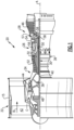
- FIG. 1 schematically illustrates a gas turbine engine 20.
- the gas turbine engine 20 is disclosed herein as a two-spool turbofan that generally incorporates a fan section 22, a compressor section 24, a combustor section 26 and a turbine section 28.
- the fan section 22 drives air along a bypass flow path B in a bypass duct defined within a housing 15 such as a fan case or nacelle, and also drives air along a core flow path C for compression and communication into the combustor section 26 then expansion through the turbine section 28.
- the exemplary engine 20 generally includes a low speed spool 30 and a high speed spool 32 mounted for rotation about an engine central longitudinal axis A relative to an engine static structure 36 via several bearing systems 38. It should be understood that various bearing systems 38 at various locations may alternatively or additionally be provided, and the location of bearing systems 38 may be varied as appropriate to the application.
- the low speed spool 30 generally includes an inner shaft 40 that interconnects, a first (or low) pressure compressor 44 and a first (or low) pressure turbine 46.
- the inner shaft 40 is connected to the fan 42 through a speed change mechanism, which in exemplary gas turbine engine 20 is illustrated as a geared architecture 48 to drive a fan 42 at a lower speed than the low speed spool 30.
- the high speed spool 32 includes an outer shaft 50 that interconnects a second (or high) pressure compressor 52 and a second (or high) pressure turbine 54.
- a combustor 56 is arranged in exemplary gas turbine 20 between the high pressure compressor 52 and the high pressure turbine 54.
- a mid-turbine frame 57 of the engine static structure 36 may be arranged generally between the high pressure turbine 54 and the low pressure turbine 46.
- the mid-turbine frame 57 further supports bearing systems 38 in the turbine section 28.
- the inner shaft 40 and the outer shaft 50 are concentric and rotate via bearing systems 38 about the engine central longitudinal axis A which is colline
- the core airflow is compressed by the low pressure compressor 44 then the high pressure compressor 52, mixed and burned with fuel in the combustor 56, then expanded through the high pressure turbine 54 and low pressure turbine 46.
- the mid-turbine frame 57 includes airfoils 59 which are in the core airflow path C.
- the turbines 46, 54 rotationally drive the respective low speed spool 30 and high speed spool 32 in response to the expansion.
- gear system 48 may be located aft of the low pressure compressor, or aft of the combustor section 26 or even aft of turbine section 28, and fan 42 may be positioned forward or aft of the location of gear system 48.
- the engine 20 in one example is a high-bypass geared aircraft engine.
- the engine 20 bypass ratio is greater than about six (6), with an example embodiment being greater than about ten (10)
- the geared architecture 48 is an epicyclic gear train, such as a planetary gear system or other gear system, with a gear reduction ratio of greater than about 2.3
- the low pressure turbine 46 has a pressure ratio that is greater than about five.
- the engine 20 bypass ratio is greater than about ten (10:1)
- the fan diameter is significantly larger than that of the low pressure compressor 44
- the low pressure turbine 46 has a pressure ratio that is greater than about five 5:1.
- Low pressure turbine 46 pressure ratio is pressure measured prior to inlet of low pressure turbine 46 as related to the pressure at the outlet of the low pressure turbine 46 prior to an exhaust nozzle.
- the geared architecture 48 may be an epicycle gear train, such as a planetary gear system or other gear system, with a gear reduction ratio of greater than about 2.3:1 and less than about 5:1. It should be understood, however, that the above parameters are only exemplary of one embodiment of a geared architecture engine and that the present invention is applicable to other gas turbine engines including direct drive turbofans.
- the fan section 22 of the engine 20 is designed for a particular flight conditiontypically cruise at about 0.8 Mach and about 35,000 feet (10,668 meters).
- the flight condition of 0.8 Mach and 35,000 ft (10,668 meters), with the engine at its best fuel consumption - also known as "bucket cruise Thrust Specific Fuel Consumption ('TSFC')" - is the industry standard parameter of lbm of fuel being burned divided by lbf of thrust the engine produces at that minimum point.
- "Low fan pressure ratio” is the pressure ratio across the fan blade alone, without a Fan Exit Guide Vane (“FEGV”) system.
- the low fan pressure ratio as disclosed herein according to one non-limiting embodiment is less than about 1.45.
- the "Low corrected fan tip speed” as disclosed herein according to one non-limiting embodiment is less than about 1150 ft / second (350.5 meters/second).
- bearings 38 support the shafts.
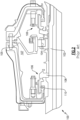
- Figure 2 shows one such bearing 104 supporting the shaft 102 of the high speed spool.
- a face seal arrangement 106 is shown at each of two sides of a bearing compartment 107.
- bearing compartment 107 may be supplied with lubricant, and the face seal arrangements 106 seal the compartment to resist migration of the lubricant outwardly of the compartment 107.
- the face seal arrangements 106 include a rotating seal seat 108 which rotates with the shaft 102, and a non-rotating face seal 110.
- the seals of the disclosure could provide benefits at any of the bearing locations shown in Figure 1 . That is, the seals could be associated with bearings supporting the low speed spool or the gear reduction and fan shaft.
- Non-rotating face seal 110 includes a sealing ring 112 having a sealing face 114 biased into contact with the seal seat 108.
- the sealing ring 112 includes a mount portion 118, a first groove 116 on an opposed side of the sealing face 114 from the seal seat 108.
- the groove 116 provides a bias area that will see high pressure air and will bias the sealing face 114 against the seal seat 108.
- a second groove 120 is shown radially outwardly of the sealing face 114.
- the groove 120 results in a sealing face 114 of a desired size.
- a proud face 119 also remains in the sealing ring 112 forward of a forward end 123 of a seal housing 122. With wear on the sealing face 114 the proud face will prevent contact between the forward end 123 of seal housing 122 and the seal seat 108.
- the seal seat is formed of a metal such as steel, titanium or nickel based alloys. However, ceramics or molybdenum alloys may also be utilized.
- a chamber 117 associated with the pressure face provided by groove 116 is at relatively high air pressure.
- a compartment 107 associated with the groove 120 and proud face 119 is at relatively low air pressure.
- a seal housing 122 carries the sealing ring 112 and provides a mount area for a coil spring 126. Coil spring 126 is mounted about a spring guide 128.
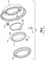
- Figure 4 shows an exploded view of the support case 124, coil springs 126, seal housing 122, sealing ring 112, and the seal seat 108.
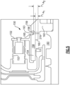
- FIG. 5 shows a face seal arrangement 150.
- Face seal arrangement 150 includes a seal housing 152 mounting coil springs 153.
- the sealing ring 154 has the mount portion 156, a sealing face 158 and grooves 160 and 163.
- a balance ratio can be defined between an area A 1 , which is the area of the face created by the groove 160 against which high pressure air in compartment 161 biases the sealing ring 154 sealing face 158 against seal seat 162, and area A 2 which is the contact area of the sealing face 158.
- the radially outer surface 159 of the seal seat 162 is shown extending radially outwardly of a radially outermost portion 165 of the proud face 219 of the sealing ring 154.
- the balance ratio is reduced.
- the balance ratio may be between 0.5 and 0.64. More narrowly, the balance ratio might be between 0.52 and 0.58. In one seal embodiment the balance ratio was 0.55.
- Figure 6 shows another embodiment 170.
- the sealing ring 174 has the mount portion 176, the groove 160 associated with a compartment 181 receiving high pressure air, a sealing face 178 and a groove 182.
- the balance ratio between areas A 1 and A 2 may be in the same ranges as in the Figure 5 embodiment.
- the area A 2 and the area A 1 are each smaller than in Figure 5 . This may provide even greater advantages, such as reducing overall seal axial closing force and heat generation, thus resulting in lower component temperatures. This should mitigate and reduce oil coke formation. Resulting benefits include reduced seal wear, and improves seal reliability.
- a width quantity is defined that speaks to the relative sizes of the sealing faces in the Figures 5 and 6 sealing ring embodiments.
- the width quantity ranges between 0.0135 and 0.0160.
- the width quantity ranges between 0.009 and 0.013.
- the radially outermost surface 179 of the seal seat 180 is radially inward of the radially outermost portion 183 of the proud face 319 sealing ring 174.
- sealing ring may be described as a carbon ring, this should not be interpreted as requiring the ring to be formed of carbon.
- sealing rings may include graphitic carbon or electrographitic carbon.
- ceramics and metallics may also be utilized within the scope of this disclosure.
- FIG. 7 Details of the seal seat 162/180 are illustrated in Figure 7 .
- a sealing face 194 would be in contact with the sealing faces 158/178.
- the ring is shown having a counter-clockwise direction of rotation in this Figure.
- each slot 196 has an inlet 198 and an outlet 200.
- Outlet 200 is spaced from the inlet 198 in a direction opposed to the direction of rotation.
- An oil slot or groove 202 extends from an inlet associated with the inner diameter 190 and communicates with the inlet 198 in the oil slots 196.
- An outlet drain hole 204 carries oil from outlet 200 to the outer diameter 192.
- a plurality of drain grooves 206 are positioned radially inward of the slots 196.
- Discharge grooves 208 extend from a downstream circumferential end of the grooves 206 to the outer periphery 192. Discharge grooves 208 could be at the other circumferential locations in grooves 206.
- Grooves and drain holes 202, 204 and 208 extend at an angle that is not directly radially outwardly relative to a rotational or central axis of the seal seat 162/180.
- the angle extends with a radially outward component, but also with a circumferential component opposed to the direction of rotation.
- the grooves may extend at different angles, including directly radially outwardly, or any number of angles include 30 degrees, 45 degrees, 50 degrees, 60 degrees, etc.
- This structure would also be preferably found in the seal seat 180.
- the moment of inertia of the seal housing and the sealing ring may be reduced.
- a reduced density may be utilized for the sealing ring than has been the case in the prior art.
- the weight of the seal housing may be reduced.
- the seal housings were formed of steel or nickel.
- the seal housing 172 may be formed of titanium alloy or ceramics, thus reducing the weight and the moment of inertia. All of these changes allow a reduction in the spring force provided by the coil spring 173 compared to the prior art.
Landscapes
- Engineering & Computer Science (AREA)
- General Engineering & Computer Science (AREA)
- Chemical & Material Sciences (AREA)
- Combustion & Propulsion (AREA)
- Mechanical Engineering (AREA)
- Physics & Mathematics (AREA)
- Fluid Mechanics (AREA)
- Mechanical Sealing (AREA)
- Sealing Using Fluids, Sealing Without Contact, And Removal Of Oil (AREA)
Claims (12)
- Gleitringdichtungsanordnung (150) für ein Gasturbinentriebwerk, wobei die Gleitringdichtungsanordnung Folgendes umfasst:einen Dichtungssitz (162), der dazu konfiguriert ist, mit einer Welle zu rotieren;ein Dichtungsgehäuse (152); undeine nicht rotierende Gleitringdichtung, wobei die nicht rotierende Gleitringdichtung einen Dichtungsring (154) beinhaltet, der an dem Dichtungsgehäuse (152) montiert ist, wobei der Dichtungsring (154) einen an dem Dichtungsgehäuse (152) montierten Montageabschnitt und eine Dichtungsfläche (158) beinhaltet, die in Kontakt mit dem Dichtungssitz (162) vorgespannt ist, wobei der Dichtungsring (154) zudem eine Nut (160) aufweist, die relativ zu dem Dichtungssitz (162) entfernt von der Dichtungsfläche definiert ist, und wobei die Nut (160) eine Druckfläche bereitstellt, die Hochdruckluft ausgesetzt wird, und eine Schraubenfeder (153) das Dichtungsgehäuse (152) in Richtung des Dichtungssitzes (162) vorspannt, derart, dass die Dichtungsfläche (158) des Dichtungsrings (154) durch Luftdruck gegen die Druckfläche und die Schraubenfeder (153) in Kontakt mit dem Dichtungssitz (162) vorgespannt wird; undein Gleichgewichtsverhältnis, das definiert ist zwischen einem Bereich (A1) der Druckfläche, der durch die Nut (160) erzeugt wird, gegen die Hochdruckluft die Dichtfläche (158) des Dichtrings (154) in Kontakt mit dem Dichtungssitz (162) vorspannt, und einem Bereich (A2) der Dichtfläche (158), der der Kontaktbereich der Dichtfläche (158) ist,dadurch gekennzeichnet, dass:das Gleichgewichtsverhältnis zwischen 0,5 und 0,64 liegt; undeine Breitengröße definiert ist als das Gleichgewichtsverhältnis multipliziert mit einer radialen Breite der Dichtfläche (158) dividiert durch einen Außendurchmesser des Dichtrings (154) an der Dichtfläche (158), und diese Breitengröße zwischen 0,009 und 0,013 oder zwischen 0,0135 und 0,0160 liegt.
- Gleitringdichtungsanordnung (150) nach Anspruch 1, wobei das Gleichgewichtsverhältnis zwischen 0,52 und 0,58 liegt.
- Gleitringdichtungsanordnung (150) nach Anspruch 1 oder 2, wobei das Dichtungsgehäuse (152) aus einem von einer Titanlegierung oder einer Keramik gebildet ist.
- Gleitringdichtungsanordnung (150) nach einem der vorhergehenden Ansprüche, wobei der Dichtungssitz (162) eine radial äußerste Oberfläche (159) aufweist und der Dichtungsring (154) eine radial äußerste Oberfläche (165) aufweist, wobei die radial äußerste Oberfläche (159) des Dichtungssitzes (162) sich von der radial äußersten Oberfläche (165) des Dichtungsrings (154) radial nach außen erstreckt.
- Gleitringdichtungsanordnung (150) nach einem der Ansprüche 1 bis 3, wobei der Dichtungssitz (162) eine radial äußerste Oberfläche (159) aufweist und der Dichtungsring (154) eine radial äußerste Oberfläche (165) aufweist, wobei die radial äußerste Oberfläche (159) des Dichtungssitzes (162) sich radial innerhalb der radial äußersten Oberfläche (165) des Dichtungsrings (154) befindet.
- Gleitringdichtungsanordnung (150) nach einem der vorhergehenden Ansprüche, wobei der Dichtungssitz (162) einen Innendurchmesser (190) und einen Außendurchmesser (192) aufweist, und wobei eine Vielzahl von Schlitzen (196) vorhanden ist, die in Umfangsrichtung beabstandet sind und einen Einlass (198) zum Empfangen von Öl von einem Innendurchmesser (190) des Dichtungssitzes (162) und einen in Umfangsrichtung beabstandeten Auslass (200) zum Auslassen von Öl zu einem Außendurchmesser (192) des Dichtungssitzes (162) aufweisen, und eine Vielzahl von Ablaufnuten (206), die in Umfangsrichtung beabstandet sind und sich radial innerhalb der Schlitze (196) befinden, und eine Zufuhrnut (202), die den Innendurchmesser (190) mit dem Einlass (198) in den Schlitzen (196) verbindet, und eine Abfuhrnut (204), die den Auslass (200) der Schlitze (196) mit dem Außendurchmesser (192) verbindet, und eine Ablaufnutabfuhrnut (208), die die Ablaufnuten (206) mit dem Außendurchmesser (192) verbindet.
- Gleitringdichtungsanordnung (150) nach Anspruch 6, wobei die Zufuhrnut (202), die Abfuhrnut (204) und die Ablaufnutabfuhrnut (208) sich alle in einem Winkel erstrecken, der nicht direkt radial nach außen von einer Drehachse des Dichtungssitzes (162) verläuft, wobei der Dichtungssitz (162) in einer ersten Umfangsrichtung rotiert und wobei die Winkel von jeder der Zufuhrnut (202), der Abfuhrnut (204) und der Ablaufnutabfuhrnut (208) eine radial äußere Komponente und eine Komponente in einer Umfangsrichtung aufweisen, die der ersten Umfangsrichtung entgegengesetzt ist.
- Gasturbinentriebwerk (20), umfassend:einen Fan (42) zum Zuführen von Luft in einen Bypass-Kanal als Antriebsluft und zu einem Kerntriebwerk, wobei das Kerntriebwerk einen Verdichterabschnitt (24) beinhaltet, der mindestens einen Verdichterrotor, einen Brennkammerabschnitt (26) und einen Turbinenabschnitt (28) einschließlich mindestens einem Turbinenrotor beinhaltet, wobei der Turbinenrotor zum Antreiben einer Welle verbunden ist, die wiederum zum Antreiben von mindestens einem des Verdichterrotors und des Fans (42) verbunden ist, wobei ein Lager an einer statischen Konstruktion außerhalb der Welle montiert ist und die Welle stützt;eine Lageraufnahme, die durch Gleitringdichtungsanordnungen (150) auf jeder der zwei axialen Seiten des Lagers definiert ist, wobei jede Gleitringdichtungsanordnung (150) eine Gleitringdichtungsanordnung (200) nach einem der vorhergehenden Ansprüche ist, jeder Dichtungssitz (162) mit der Welle rotiert und jede Nut (160) eine Druckfläche bereitstellt, die Hochdruckluft außerhalb der Lageraufnahme (107) ausgesetzt wird.
- Gasturbinentriebwerk (20) nach Anspruch 8, wobei der mindestens eine Verdichterrotor einen Hochdrehzahlverdichterrotor und einen Niedrigdrehzahlverdichterrotor beinhaltet und der mindestens eine Turbinenrotor einen Hochdrehzahlturbinenrotor und einen Niedrigdrehzahlturbinenrotor beinhaltet und ein Niedrigdrehzahlturbinenrotor den Niedrigdrehzahlverdichterrotor über eine Niedrigdrehzahlwelle (40) antreibt und der Hochdrehzahlturbinenrotor den Hochdrehzahlverdichterrotor über eine Hochdrehzahlwelle (50) antreibt.
- Gasturbinentriebwerk (20) nach Anspruch 9, wobei die Hochdrehzahlwelle (50) die von dem Lager getragene Welle ist.
- Gasturbinentriebwerk (20) nach Anspruch 9, wobei die Niedrigdrehzahlwelle (40) die von dem Lager getragene Welle (102) ist.
- Gasturbinentriebwerk (20) nach Anspruch 9, wobei die Niedrigdrehzahlwelle (40) zudem den Fanrotor über ein Untersetzungsgetriebe (48) antreibt und das Untersetzungsgetriebe (48) eine Fanwelle antreibt, wobei die Fanwelle die von dem Lager getragene Welle ist.
Applications Claiming Priority (1)
| Application Number | Priority Date | Filing Date | Title |
|---|---|---|---|
| US17/104,459 US11459956B2 (en) | 2020-11-25 | 2020-11-25 | Face seal arrangement with reduced balance ratio |
Publications (2)
| Publication Number | Publication Date |
|---|---|
| EP4006310A1 EP4006310A1 (de) | 2022-06-01 |
| EP4006310B1 true EP4006310B1 (de) | 2025-03-05 |
Family
ID=78789910
Family Applications (1)
| Application Number | Title | Priority Date | Filing Date |
|---|---|---|---|
| EP21210583.7A Active EP4006310B1 (de) | 2020-11-25 | 2021-11-25 | Gleitringdichtungsanordnung mit reduziertem gleichgewichtsverhältnis |
Country Status (2)
| Country | Link |
|---|---|
| US (1) | US11459956B2 (de) |
| EP (1) | EP4006310B1 (de) |
Families Citing this family (1)
| Publication number | Priority date | Publication date | Assignee | Title |
|---|---|---|---|---|
| US11946548B2 (en) | 2021-06-16 | 2024-04-02 | Rtx Corporation | Coil spring carbon face seal |
Citations (1)
| Publication number | Priority date | Publication date | Assignee | Title |
|---|---|---|---|---|
| US4934254A (en) * | 1982-05-24 | 1990-06-19 | Clark Eugene V | Face seal with long-wearing sealing surface |
Family Cites Families (13)
| Publication number | Priority date | Publication date | Assignee | Title |
|---|---|---|---|---|
| US4212475A (en) | 1979-01-15 | 1980-07-15 | Crane Packing Co. | Self aligning spiral groove face seal |
| US4406459A (en) | 1982-06-18 | 1983-09-27 | United Technologies Corporation | Oil weepage return for carbon seal plates |
| US5938206A (en) | 1996-11-01 | 1999-08-17 | John Crane Inc. | Pressure responsive primary ring for a non-contacting mechanical end face seal |
| EP1601890B1 (de) * | 2003-02-28 | 2019-11-27 | A.W. Chesterton Company | Ausgeglichene mechanische dichtungsanordnung |
| WO2004079235A2 (en) * | 2003-02-28 | 2004-09-16 | A.W. Chesterton Company | Balanced mechanical seal assembly |
| JP3792205B2 (ja) * | 2003-03-03 | 2006-07-05 | 日本ピラー工業株式会社 | メカニカルシール |
| JP5557752B2 (ja) * | 2009-09-24 | 2014-07-23 | イーグル工業株式会社 | メカニカルシール |
| US9683451B2 (en) * | 2013-01-04 | 2017-06-20 | United Technologies Corporation | Seal assembly for arranging between a stator and a rotor |
| US9644745B2 (en) * | 2013-11-12 | 2017-05-09 | Eagle Industry Co., Ltd. | Mechanical seal |
| US9732622B1 (en) * | 2015-06-16 | 2017-08-15 | Florida Turbine Technologies, Inc. | Self-balancing air riding seal for a turbine |
| US10788131B2 (en) | 2017-08-01 | 2020-09-29 | Raytheon Technologies Corporation | Face seal arrangement |
| US10385713B2 (en) | 2017-08-24 | 2019-08-20 | United Technologies Corporation | Seal assembly for gas turbine engines |
| US10619741B2 (en) | 2017-09-12 | 2020-04-14 | United Technologies Corporation | Contacting dry face seal with tapered carbon nose |
-
2020
- 2020-11-25 US US17/104,459 patent/US11459956B2/en active Active
-
2021
- 2021-11-25 EP EP21210583.7A patent/EP4006310B1/de active Active
Patent Citations (1)
| Publication number | Priority date | Publication date | Assignee | Title |
|---|---|---|---|---|
| US4934254A (en) * | 1982-05-24 | 1990-06-19 | Clark Eugene V | Face seal with long-wearing sealing surface |
Also Published As
| Publication number | Publication date |
|---|---|
| US11459956B2 (en) | 2022-10-04 |
| US20220162994A1 (en) | 2022-05-26 |
| EP4006310A1 (de) | 2022-06-01 |
Similar Documents
| Publication | Publication Date | Title |
|---|---|---|
| EP4006311B1 (de) | Gleitringdichtungsanordnung mit reduzierter kraft und reduziertem druck | |
| EP2964928B1 (de) | Berührungslose dichtungen für lagerkammern eines verzahnten gasturbinenmotors | |
| US9546560B2 (en) | Compact double grounded mechanical carbon seal | |
| EP3447251B1 (de) | Dichtungssatz für gasturbinentriebwerke | |
| EP3453838B1 (de) | Trockengleitringdichtung mit kegelstumpfförmiger kohlenstoffkontaktfläche | |
| EP3428408B1 (de) | Einsatzelement am ende einer verstellbaren schaufel in einem gasturbinentriebwerk | |
| EP3822459B1 (de) | Deckbandsegment mit kühlungsnut | |
| EP4006310B1 (de) | Gleitringdichtungsanordnung mit reduziertem gleichgewichtsverhältnis | |
| EP4012162B1 (de) | Drehhülse zur steuerung des spiels einer dichtungsanordnung einer gasturbine | |
| EP3835606B1 (de) | Feder zur zentrierung eines gekrümmten trägers für ein drucklager | |
| US12180840B1 (en) | Seal assembly for a turbine engine | |
| EP3819474A1 (de) | Plattformdichtung für ein gasturbinentriebwerk | |
| EP2955332B1 (de) | Getriebedichtung eines gasturbinenmotors mit getriebe-fan | |
| EP4386179A1 (de) | Gasturbinenmotor mit geteilter spiralförmiger kolbendichtung | |
| US11649729B2 (en) | Anti-vortex tube retaining ring and bore basket | |
| EP3957832B1 (de) | Integraler zahnradträger und lagerdämpfersockel eines gasturbinentriebwerks | |
| US11371376B2 (en) | Sealing surface for ceramic matrix composite blade outer air seal | |
| EP4047189A1 (de) | Berührungslose dichtungsanordnung mit innenbeschichtung | |
| EP3372793B1 (de) | Berührungslose dichtungen für lagerkammern eines verzahnten gasturbinenmotors | |
| US20250334058A1 (en) | Sleeve for serially-arranged seal elements |
Legal Events
| Date | Code | Title | Description |
|---|---|---|---|
| PUAI | Public reference made under article 153(3) epc to a published international application that has entered the european phase |
Free format text: ORIGINAL CODE: 0009012 |
|
| STAA | Information on the status of an ep patent application or granted ep patent |
Free format text: STATUS: THE APPLICATION HAS BEEN PUBLISHED |
|
| AK | Designated contracting states |
Kind code of ref document: A1 Designated state(s): AL AT BE BG CH CY CZ DE DK EE ES FI FR GB GR HR HU IE IS IT LI LT LU LV MC MK MT NL NO PL PT RO RS SE SI SK SM TR |
|
| STAA | Information on the status of an ep patent application or granted ep patent |
Free format text: STATUS: REQUEST FOR EXAMINATION WAS MADE |
|
| 17P | Request for examination filed |
Effective date: 20221201 |
|
| RBV | Designated contracting states (corrected) |
Designated state(s): AL AT BE BG CH CY CZ DE DK EE ES FI FR GB GR HR HU IE IS IT LI LT LU LV MC MK MT NL NO PL PT RO RS SE SI SK SM TR |
|
| RAP3 | Party data changed (applicant data changed or rights of an application transferred) |
Owner name: RTX CORPORATION |
|
| GRAP | Despatch of communication of intention to grant a patent |
Free format text: ORIGINAL CODE: EPIDOSNIGR1 |
|
| STAA | Information on the status of an ep patent application or granted ep patent |
Free format text: STATUS: GRANT OF PATENT IS INTENDED |
|
| INTG | Intention to grant announced |
Effective date: 20240925 |
|
| GRAS | Grant fee paid |
Free format text: ORIGINAL CODE: EPIDOSNIGR3 |
|
| GRAA | (expected) grant |
Free format text: ORIGINAL CODE: 0009210 |
|
| STAA | Information on the status of an ep patent application or granted ep patent |
Free format text: STATUS: THE PATENT HAS BEEN GRANTED |
|
| AK | Designated contracting states |
Kind code of ref document: B1 Designated state(s): AL AT BE BG CH CY CZ DE DK EE ES FI FR GB GR HR HU IE IS IT LI LT LU LV MC MK MT NL NO PL PT RO RS SE SI SK SM TR |
|
| REG | Reference to a national code |
Ref country code: GB Ref legal event code: FG4D |
|
| REG | Reference to a national code |
Ref country code: CH Ref legal event code: EP |
|
| REG | Reference to a national code |
Ref country code: IE Ref legal event code: FG4D |
|
| REG | Reference to a national code |
Ref country code: DE Ref legal event code: R096 Ref document number: 602021027087 Country of ref document: DE |
|
| PG25 | Lapsed in a contracting state [announced via postgrant information from national office to epo] |
Ref country code: RS Free format text: LAPSE BECAUSE OF FAILURE TO SUBMIT A TRANSLATION OF THE DESCRIPTION OR TO PAY THE FEE WITHIN THE PRESCRIBED TIME-LIMIT Effective date: 20250605 |
|
| PG25 | Lapsed in a contracting state [announced via postgrant information from national office to epo] |
Ref country code: FI Free format text: LAPSE BECAUSE OF FAILURE TO SUBMIT A TRANSLATION OF THE DESCRIPTION OR TO PAY THE FEE WITHIN THE PRESCRIBED TIME-LIMIT Effective date: 20250305 |
|
| REG | Reference to a national code |
Ref country code: NL Ref legal event code: MP Effective date: 20250305 |
|
| PG25 | Lapsed in a contracting state [announced via postgrant information from national office to epo] |
Ref country code: ES Free format text: LAPSE BECAUSE OF FAILURE TO SUBMIT A TRANSLATION OF THE DESCRIPTION OR TO PAY THE FEE WITHIN THE PRESCRIBED TIME-LIMIT Effective date: 20250305 |
|
| REG | Reference to a national code |
Ref country code: LT Ref legal event code: MG9D |
|
| PG25 | Lapsed in a contracting state [announced via postgrant information from national office to epo] |
Ref country code: NO Free format text: LAPSE BECAUSE OF FAILURE TO SUBMIT A TRANSLATION OF THE DESCRIPTION OR TO PAY THE FEE WITHIN THE PRESCRIBED TIME-LIMIT Effective date: 20250605 |
|
| PG25 | Lapsed in a contracting state [announced via postgrant information from national office to epo] |
Ref country code: HR Free format text: LAPSE BECAUSE OF FAILURE TO SUBMIT A TRANSLATION OF THE DESCRIPTION OR TO PAY THE FEE WITHIN THE PRESCRIBED TIME-LIMIT Effective date: 20250305 |
|
| PG25 | Lapsed in a contracting state [announced via postgrant information from national office to epo] |
Ref country code: LV Free format text: LAPSE BECAUSE OF FAILURE TO SUBMIT A TRANSLATION OF THE DESCRIPTION OR TO PAY THE FEE WITHIN THE PRESCRIBED TIME-LIMIT Effective date: 20250305 |
|
| PG25 | Lapsed in a contracting state [announced via postgrant information from national office to epo] |
Ref country code: GR Free format text: LAPSE BECAUSE OF FAILURE TO SUBMIT A TRANSLATION OF THE DESCRIPTION OR TO PAY THE FEE WITHIN THE PRESCRIBED TIME-LIMIT Effective date: 20250606 Ref country code: BG Free format text: LAPSE BECAUSE OF FAILURE TO SUBMIT A TRANSLATION OF THE DESCRIPTION OR TO PAY THE FEE WITHIN THE PRESCRIBED TIME-LIMIT Effective date: 20250305 |
|
| REG | Reference to a national code |
Ref country code: AT Ref legal event code: MK05 Ref document number: 1773099 Country of ref document: AT Kind code of ref document: T Effective date: 20250305 |
|
| PG25 | Lapsed in a contracting state [announced via postgrant information from national office to epo] |
Ref country code: NL Free format text: LAPSE BECAUSE OF FAILURE TO SUBMIT A TRANSLATION OF THE DESCRIPTION OR TO PAY THE FEE WITHIN THE PRESCRIBED TIME-LIMIT Effective date: 20250305 |
|
| PG25 | Lapsed in a contracting state [announced via postgrant information from national office to epo] |
Ref country code: SE Free format text: LAPSE BECAUSE OF FAILURE TO SUBMIT A TRANSLATION OF THE DESCRIPTION OR TO PAY THE FEE WITHIN THE PRESCRIBED TIME-LIMIT Effective date: 20250305 |
|
| PG25 | Lapsed in a contracting state [announced via postgrant information from national office to epo] |
Ref country code: SM Free format text: LAPSE BECAUSE OF FAILURE TO SUBMIT A TRANSLATION OF THE DESCRIPTION OR TO PAY THE FEE WITHIN THE PRESCRIBED TIME-LIMIT Effective date: 20250305 |
|
| PG25 | Lapsed in a contracting state [announced via postgrant information from national office to epo] |
Ref country code: PT Free format text: LAPSE BECAUSE OF FAILURE TO SUBMIT A TRANSLATION OF THE DESCRIPTION OR TO PAY THE FEE WITHIN THE PRESCRIBED TIME-LIMIT Effective date: 20250707 |
|
| PG25 | Lapsed in a contracting state [announced via postgrant information from national office to epo] |
Ref country code: IT Free format text: LAPSE BECAUSE OF FAILURE TO SUBMIT A TRANSLATION OF THE DESCRIPTION OR TO PAY THE FEE WITHIN THE PRESCRIBED TIME-LIMIT Effective date: 20250305 Ref country code: PL Free format text: LAPSE BECAUSE OF FAILURE TO SUBMIT A TRANSLATION OF THE DESCRIPTION OR TO PAY THE FEE WITHIN THE PRESCRIBED TIME-LIMIT Effective date: 20250305 |
|
| PG25 | Lapsed in a contracting state [announced via postgrant information from national office to epo] |
Ref country code: AT Free format text: LAPSE BECAUSE OF FAILURE TO SUBMIT A TRANSLATION OF THE DESCRIPTION OR TO PAY THE FEE WITHIN THE PRESCRIBED TIME-LIMIT Effective date: 20250305 |
|
| PG25 | Lapsed in a contracting state [announced via postgrant information from national office to epo] |
Ref country code: EE Free format text: LAPSE BECAUSE OF FAILURE TO SUBMIT A TRANSLATION OF THE DESCRIPTION OR TO PAY THE FEE WITHIN THE PRESCRIBED TIME-LIMIT Effective date: 20250305 Ref country code: CZ Free format text: LAPSE BECAUSE OF FAILURE TO SUBMIT A TRANSLATION OF THE DESCRIPTION OR TO PAY THE FEE WITHIN THE PRESCRIBED TIME-LIMIT Effective date: 20250305 |
|
| PG25 | Lapsed in a contracting state [announced via postgrant information from national office to epo] |
Ref country code: RO Free format text: LAPSE BECAUSE OF FAILURE TO SUBMIT A TRANSLATION OF THE DESCRIPTION OR TO PAY THE FEE WITHIN THE PRESCRIBED TIME-LIMIT Effective date: 20250305 |
|
| PG25 | Lapsed in a contracting state [announced via postgrant information from national office to epo] |
Ref country code: SK Free format text: LAPSE BECAUSE OF FAILURE TO SUBMIT A TRANSLATION OF THE DESCRIPTION OR TO PAY THE FEE WITHIN THE PRESCRIBED TIME-LIMIT Effective date: 20250305 |
|
| PG25 | Lapsed in a contracting state [announced via postgrant information from national office to epo] |
Ref country code: IS Free format text: LAPSE BECAUSE OF FAILURE TO SUBMIT A TRANSLATION OF THE DESCRIPTION OR TO PAY THE FEE WITHIN THE PRESCRIBED TIME-LIMIT Effective date: 20250705 |
|
| REG | Reference to a national code |
Ref country code: DE Ref legal event code: R097 Ref document number: 602021027087 Country of ref document: DE |
|
| PGFP | Annual fee paid to national office [announced via postgrant information from national office to epo] |
Ref country code: DE Payment date: 20251022 Year of fee payment: 5 |
|
| PGFP | Annual fee paid to national office [announced via postgrant information from national office to epo] |
Ref country code: GB Payment date: 20251023 Year of fee payment: 5 |
|
| PLBE | No opposition filed within time limit |
Free format text: ORIGINAL CODE: 0009261 |
|
| STAA | Information on the status of an ep patent application or granted ep patent |
Free format text: STATUS: NO OPPOSITION FILED WITHIN TIME LIMIT |
|
| PG25 | Lapsed in a contracting state [announced via postgrant information from national office to epo] |
Ref country code: DK Free format text: LAPSE BECAUSE OF FAILURE TO SUBMIT A TRANSLATION OF THE DESCRIPTION OR TO PAY THE FEE WITHIN THE PRESCRIBED TIME-LIMIT Effective date: 20250305 |
|
| REG | Reference to a national code |
Ref country code: CH Ref legal event code: L10 Free format text: ST27 STATUS EVENT CODE: U-0-0-L10-L00 (AS PROVIDED BY THE NATIONAL OFFICE) Effective date: 20260114 |
|
| PGFP | Annual fee paid to national office [announced via postgrant information from national office to epo] |
Ref country code: FR Payment date: 20251022 Year of fee payment: 5 |
|
| 26N | No opposition filed |
Effective date: 20251208 |