EP4006304B1 - Turbine blade for a gas turbine engine and gas turbine engine - Google Patents
Turbine blade for a gas turbine engine and gas turbine engine Download PDFInfo
- Publication number
- EP4006304B1 EP4006304B1 EP21210883.1A EP21210883A EP4006304B1 EP 4006304 B1 EP4006304 B1 EP 4006304B1 EP 21210883 A EP21210883 A EP 21210883A EP 4006304 B1 EP4006304 B1 EP 4006304B1
- Authority
- EP
- European Patent Office
- Prior art keywords
- tip
- bump
- airfoil
- wall
- turbine
- Prior art date
- Legal status (The legal status is an assumption and is not a legal conclusion. Google has not performed a legal analysis and makes no representation as to the accuracy of the status listed.)
- Active
Links
- 230000003014 reinforcing effect Effects 0.000 claims description 64
- 230000002093 peripheral effect Effects 0.000 claims description 57
- 238000001816 cooling Methods 0.000 claims description 21
- 239000012809 cooling fluid Substances 0.000 claims 1
- 239000007789 gas Substances 0.000 description 20
- 239000000567 combustion gas Substances 0.000 description 10
- 230000035882 stress Effects 0.000 description 6
- 230000007423 decrease Effects 0.000 description 4
- 238000005516 engineering process Methods 0.000 description 3
- 239000000463 material Substances 0.000 description 3
- 238000005050 thermomechanical fatigue Methods 0.000 description 3
- 230000003247 decreasing effect Effects 0.000 description 2
- 230000000694 effects Effects 0.000 description 2
- 230000004907 flux Effects 0.000 description 2
- 230000014509 gene expression Effects 0.000 description 2
- 230000006872 improvement Effects 0.000 description 2
- 238000012986 modification Methods 0.000 description 2
- 230000004048 modification Effects 0.000 description 2
- 230000009467 reduction Effects 0.000 description 2
- 239000000956 alloy Substances 0.000 description 1
- 229910045601 alloy Inorganic materials 0.000 description 1
- 238000005452 bending Methods 0.000 description 1
- 230000008859 change Effects 0.000 description 1
- 238000004891 communication Methods 0.000 description 1
- 230000001934 delay Effects 0.000 description 1
- 230000006353 environmental stress Effects 0.000 description 1
- 239000000446 fuel Substances 0.000 description 1
- 238000000034 method Methods 0.000 description 1
- 230000008439 repair process Effects 0.000 description 1
- 238000007789 sealing Methods 0.000 description 1
- 230000008719 thickening Effects 0.000 description 1
- 238000011144 upstream manufacturing Methods 0.000 description 1
Images
Classifications
-
- F—MECHANICAL ENGINEERING; LIGHTING; HEATING; WEAPONS; BLASTING
- F01—MACHINES OR ENGINES IN GENERAL; ENGINE PLANTS IN GENERAL; STEAM ENGINES
- F01D—NON-POSITIVE DISPLACEMENT MACHINES OR ENGINES, e.g. STEAM TURBINES
- F01D5/00—Blades; Blade-carrying members; Heating, heat-insulating, cooling or antivibration means on the blades or the members
- F01D5/12—Blades
- F01D5/14—Form or construction
- F01D5/18—Hollow blades, i.e. blades with cooling or heating channels or cavities; Heating, heat-insulating or cooling means on blades
-
- F—MECHANICAL ENGINEERING; LIGHTING; HEATING; WEAPONS; BLASTING
- F01—MACHINES OR ENGINES IN GENERAL; ENGINE PLANTS IN GENERAL; STEAM ENGINES
- F01D—NON-POSITIVE DISPLACEMENT MACHINES OR ENGINES, e.g. STEAM TURBINES
- F01D5/00—Blades; Blade-carrying members; Heating, heat-insulating, cooling or antivibration means on the blades or the members
- F01D5/12—Blades
- F01D5/14—Form or construction
- F01D5/20—Specially-shaped blade tips to seal space between tips and stator
-
- F—MECHANICAL ENGINEERING; LIGHTING; HEATING; WEAPONS; BLASTING
- F01—MACHINES OR ENGINES IN GENERAL; ENGINE PLANTS IN GENERAL; STEAM ENGINES
- F01D—NON-POSITIVE DISPLACEMENT MACHINES OR ENGINES, e.g. STEAM TURBINES
- F01D5/00—Blades; Blade-carrying members; Heating, heat-insulating, cooling or antivibration means on the blades or the members
- F01D5/12—Blades
- F01D5/14—Form or construction
- F01D5/147—Construction, i.e. structural features, e.g. of weight-saving hollow blades
-
- F—MECHANICAL ENGINEERING; LIGHTING; HEATING; WEAPONS; BLASTING
- F05—INDEXING SCHEMES RELATING TO ENGINES OR PUMPS IN VARIOUS SUBCLASSES OF CLASSES F01-F04
- F05D—INDEXING SCHEME FOR ASPECTS RELATING TO NON-POSITIVE-DISPLACEMENT MACHINES OR ENGINES, GAS-TURBINES OR JET-PROPULSION PLANTS
- F05D2240/00—Components
- F05D2240/20—Rotors
- F05D2240/30—Characteristics of rotor blades, i.e. of any element transforming dynamic fluid energy to or from rotational energy and being attached to a rotor
- F05D2240/301—Cross-sectional characteristics
-
- F—MECHANICAL ENGINEERING; LIGHTING; HEATING; WEAPONS; BLASTING
- F05—INDEXING SCHEMES RELATING TO ENGINES OR PUMPS IN VARIOUS SUBCLASSES OF CLASSES F01-F04
- F05D—INDEXING SCHEME FOR ASPECTS RELATING TO NON-POSITIVE-DISPLACEMENT MACHINES OR ENGINES, GAS-TURBINES OR JET-PROPULSION PLANTS
- F05D2240/00—Components
- F05D2240/20—Rotors
- F05D2240/30—Characteristics of rotor blades, i.e. of any element transforming dynamic fluid energy to or from rotational energy and being attached to a rotor
- F05D2240/305—Characteristics of rotor blades, i.e. of any element transforming dynamic fluid energy to or from rotational energy and being attached to a rotor related to the pressure side of a rotor blade
-
- F—MECHANICAL ENGINEERING; LIGHTING; HEATING; WEAPONS; BLASTING
- F05—INDEXING SCHEMES RELATING TO ENGINES OR PUMPS IN VARIOUS SUBCLASSES OF CLASSES F01-F04
- F05D—INDEXING SCHEME FOR ASPECTS RELATING TO NON-POSITIVE-DISPLACEMENT MACHINES OR ENGINES, GAS-TURBINES OR JET-PROPULSION PLANTS
- F05D2240/00—Components
- F05D2240/20—Rotors
- F05D2240/30—Characteristics of rotor blades, i.e. of any element transforming dynamic fluid energy to or from rotational energy and being attached to a rotor
- F05D2240/307—Characteristics of rotor blades, i.e. of any element transforming dynamic fluid energy to or from rotational energy and being attached to a rotor related to the tip of a rotor blade
-
- F—MECHANICAL ENGINEERING; LIGHTING; HEATING; WEAPONS; BLASTING
- F05—INDEXING SCHEMES RELATING TO ENGINES OR PUMPS IN VARIOUS SUBCLASSES OF CLASSES F01-F04
- F05D—INDEXING SCHEME FOR ASPECTS RELATING TO NON-POSITIVE-DISPLACEMENT MACHINES OR ENGINES, GAS-TURBINES OR JET-PROPULSION PLANTS
- F05D2250/00—Geometry
- F05D2250/70—Shape
- F05D2250/71—Shape curved
- F05D2250/711—Shape curved convex
-
- F—MECHANICAL ENGINEERING; LIGHTING; HEATING; WEAPONS; BLASTING
- F05—INDEXING SCHEMES RELATING TO ENGINES OR PUMPS IN VARIOUS SUBCLASSES OF CLASSES F01-F04
- F05D—INDEXING SCHEME FOR ASPECTS RELATING TO NON-POSITIVE-DISPLACEMENT MACHINES OR ENGINES, GAS-TURBINES OR JET-PROPULSION PLANTS
- F05D2260/00—Function
- F05D2260/20—Heat transfer, e.g. cooling
Definitions
- the invention relates generally to gas turbine engines, and more particularly to blades used in turbine sections of such engines in accordance with the independent claims.
- the invention treats from a turbine blade for a gas turbine engine and from a gas turbine engine.
- a turbine blade used in a gas turbine engine has a radially outward blade tip that rotates at high speed relative to a peripheral shroud defining a gaspath of the engine. Maintaining a minimal gap between the blade tip and the peripheral shroud is important to maintain efficiency.
- a tip of an internally cooled turbine blade is cooled with cooling air exhausted through openings in the tip.
- the turbine blade tips are exposed to high gas temperature and mechanical forces imposed by the high rotation speed.
- Thermo-mechanical fatigue life of the airfoil and blade tips in particular can determine the repair cycle of an engine which may involve removal and replacement of turbine blades. Improvement is desirable to reduce the costs and delays involved with engine downtime caused by thermo-mechanical fatigue of turbine blade tips.
- EP 3,255,249 discloses a gas turbine engine blade including a squealer tip pocket and discloses the preamble of claim 1.
- EP 2,944,764 discloses a component, a corresponding gas turbine engine and a method of cooling, and discloses the preamble of claim 1.
- a turbine blade for a gas turbine engine comprising: an airfoil extending along a span from a base to a tip and along a chord from a leading edge to a trailing edge, the airfoil having a pressure side and a suction side, a tip pocket at the tip of the airfoil, the tip pocket at least partially surrounded by a peripheral tip wall defining a portion of the pressure and suction sides; at least one internal cooling passage in the airfoil, the at least one internal cooling passage having at least one outlet communicating with the tip pocket; and a reinforcing bump located on the pressure side of the airfoil and protruding from a baseline surface of the peripheral tip wall to a bump end located into the tip pocket, the reinforcing bump overlapping a location where a curvature of a concave portion of the pressure side of the airfoil is maximal.
- a thickness of the peripheral tip wall at the reinforcing bump corresponds to a nominal thickness of the peripheral tip wall at a location adjacent the reinforcing bump plus a bump thickness of the reinforcing bump.
- the tip pocket is bounded by the peripheral tip wall and by a bottom wall, the bottom wall extending from the pressure side to the suction side, the bump extending from the bottom wall to the tip.
- a ratio of the thickness to the nominal thickness is between 1.5 and 2.5.
- the ratio of the thickness to the nominal thickness is about 1.75.
- a chordwise position of a center of the reinforcing bump is between chordwise positions of two outlets of the at least one outlet.
- a width of the reinforcing bump taken in a direction along the chord of the airfoil is about 10% of the chord of the airfoil.
- the reinforcing bump is located closer to the leading edge than to the trailing edge.
- a center of the reinforcing bump is located at from 15% to 25% of the chord from the leading edge.
- the bump end is spaced apart from the suction side.
- the bump end of the reinforcing bump is closer to the baseline surface than to the suction side.
- the turbine section includes a high-pressure turbine and a low-pressure turbine, the rotor being part of the high-pressure turbine, the rotor being a single rotor of the high-pressure turbine.
- a ratio of the thickness to the nominal thickness is between 1.5 and 2.5.
- Fig. 1 illustrates a gas turbine engine 10 of a type preferably provided for use in subsonic flight for driving a load 12, such as, but not limited to, a propeller or a helicopter rotor.
- the engine 10 may be any suitable aircraft engine.
- the engine 10 is a gas turbine engine, and more particularly a turboprop, and generally comprises in serial flow communication a compressor section 14 for pressurizing the air, a combustor 16 in which the compressed air is mixed with fuel and ignited for generating an annular stream of hot combustion gases, and a turbine section 18 for extracting energy from the combustion gases.
- the exemplary embodiment shown in Fig. 1 is a "reverse-flow” engine because gases flow within an annular gaspath 26 from an inlet 17, at a rear portion of the engine 10, to an exhaust outlet 19, at a front portion of the engine 10, relative to a direction of travel T of the engine 10.
- This is in contrast to "through-flow" gas turbine engines in which gases flow through the core of the engine 10 from a front portion to a rear portion, in a direction opposite the direction of travel T.
- the engine 10 may be a reverse-flow engine (as illustrated) or a through-flow engine.
- the principles of the present disclosure can be applied to both reverse-flow and through-flow engines and to any other gas turbine engines, such as a turbofan engine and a turboshaft engine.
- the turbine section 18 has a high-pressure turbine 18A in driving engagement with a high-pressure compressor 14A.
- the high-pressure turbine 18A and the high-pressure compressor 14A are mounted on a high-pressure shaft 15.
- the turbine section 18 has a low-pressure turbine, also known as power turbine 18B drivingly engaged to the load 12.
- the power turbine 18B is drivingly engaged to a low-pressure compressor 14B via a low-pressure shaft 22.
- a gearbox 20, which may be a planetary gearbox, is configured as a reduction gearbox and operatively connects the low-pressure shaft 22 that is driven by the power turbine 18B to a shaft 24 that is in driving engagement with the load 12, while providing a reduction speed ratio therebetween.
- the load 12 is a rotor of an aircraft, and more particularly a propeller, and thus the shaft 24 driving the aircraft rotor is referred to as a rotor shaft.
- upstream and downstream refer to the direction of an air/gas flow passing through the annular gaspath 26 of the gas turbine engine 10.
- axial refers to the direction of an air/gas flow passing through the annular gaspath 26 of the gas turbine engine 10.
- axial refers to a central axis 11 of the gaspath 26, which may also be a central axis of gas turbine engine 10.
- expressions such as “extending radially” as used herein does not necessarily imply extending perfectly radially along a ray perfectly perpendicular to the central axis 11, but is intended to encompass a direction of extension that has a radial component relative to the central axis 11.
- the high-pressure turbine 18a includes a rotor having a central hub 29 and a peripheral array of replaceable turbine blades 30. Any of the rotors of any of the high-pressure turbine 18a and the low-pressure turbine 18b may include blades as will be described herein below. In the embodiment shown, the disclosed turbine blades 30 are part of the high-pressure turbine 18a, which, in the present case, includes a single rotor.
- the blade 30 has a platform 31 exposed to the annular gaspath 26 and a root 32 ( Fig. 3 ) protruding inwardly from the platform 31.
- the root 32 is received within correspondingly shaped slots defined by the central hub 29 ( Fig. 1 ) to hold the blade 30 while the rotor is rotating about the central axis 11.
- the blade 30 has an airfoil 33 protruding from the platform 31 away from the root 32 along a span S.
- the airfoil 33 has a base 33a at the platform 31 and a tip 33b radially spaced apart from the root 33a relative to the central axis 11.
- the airfoil 33 hence extends along a direction having a radial component relative to the central axis 11 from the base 33a to the tip 33b.
- the airfoil 33 has a leading edge 33c, a trailing edge 33d spaced apart from the leading edge 33c by a chord C ( Fig. 4 ), a pressure side 33e and a suction side 33f opposed to the pressure side 33e.
- the pressure and suction sides 33e, 33f extend from the leading edge 33c to the trailing edge 33d and from the base 33a to the tip 33b.
- the chord C is depicted here as a straight line connecting the leading edge 33c to the trailing edge 33d.
- the chord C may vary along the span S of the airfoil 33 between the base 33a and the tip 33b.
- the chord C differs from a camber line CL ( Fig. 6 ), which corresponds to a line that may be curved and that connects the leading edge 33c to the trailing edge 33d and that is centered between the pressure and suctions sides 33e, 33f.
- CL camber line
- the chord C is the one taken at a corresponding spanwise location (e.g., tip 33b) between the base 33a and the tip 33b.
- the blade 30 has a tip pocket, also referred to as tip plenum, 34 circumscribed by a peripheral tip wall 35.
- the peripheral tip wall 35 defines a portion of the pressure side 33e and a portion of the section side 33f.
- the blade has an end wall which defines a bottom wall 36 of the tip plenum.
- the bottom wall 36 extends from the pressure side 33e to the suction side 33f.
- the tip pocket 34 is therefore substantially bounded by the peripheral tip wall 35 and the bottom wall 36.
- the blade 30 defines internal cooling passages 37 (only one cooling passage may be present) ( Fig. 3 ) within the airfoil 33.
- the cooling passages 37 have tip outlets 37a, 37b communicating with the tip pocket 34 and side outlets 37c located between the base 33a and the tip 33b proximate the trailing edge 33d and through the pressure and/or suction sides 33e, 33f.
- the tip outlets 37a, 37b may differ by their diameter and, hence, by a mass flow rate of cooling air flowing therethrough.
- the tip outlets 37a, 37b includes a first tip outlet 37a proximate the leading edge 33c of the airfoil 33 and a plurality of second tip outlets located between the first tip outlet 37a and the trailing edge 33d.
- the first and second tip outlets 37a, 37b are distributed along a camber line of the airfoil between the leading edge 33c and the trailing edge 33d.
- Diameters of the second tip outlets 37b decrease from the leading edge 33c to the trailing edge 33d because of a distance between the pressure and suction sides 33e, 33f decreases toward the trailing edge 33d. They may have a constant diameter. A density of the second tip outlets 37b may increase toward the trailing edge 33d to compensate for their smaller diameter.
- the cooling air may come from the compressor section 14 ( Fig. 1 ) of the gas turbine engine 10. Many factors are involved in determining the position and size of the tip outlets: pressure distribution between the inside of the blade and the outside, the flow structure (orientation, etc) inside the blade, etc.
- the rotor of the high-pressure turbine 18a of the turbine section 18 rotates at high speed about the central axis 11.
- the pressure of the combustion gases at the pressure side 33e of the airfoil 33 is greater than that at the suction side 33f of the airfoil 33. This tends to induce a phenomenon known as "tip leakage" where the combustion gases tend to flow from the pressure side 33e to the suction side 33f of the airfoil 33 around the tip 33b.
- This may impair efficiency of the turbine section 18 because the turbine section 18 is not able to extract as much energy from the combustion gases as it could if no tip leakage were present.
- the peripheral tip wall 35 is created.
- the peripheral tip wall 35 has a pressure side portion 35a and a suction side portion 35b spaced apart from the pressure side portion 35a by the pocket 34.
- the pressure and suction sides portions 35a, 35b of the peripheral tip wall 35 act as knife edges of a labyrinth seal and contributes in decreasing an amount of the combustion gases that flows within a gap between the tip 33b of the airfoil 33 and turbine shrouds circumferentially distributed around the blades 30 compared to a configuration in which the tip pocket 34 is absent.
- implementing the tip pocket 34 creates two knife edges, which corresponds here as the pressure and suction sides portions 35a, 35b of the peripheral tip wall 35.
- a thickness T1 of the peripheral tip wall 35 may be quite small. In the embodiment shown, the thickness T1 is about 0.02 inch (0.05 cm).
- Some locations of the peripheral tip wall 35 are simultaneously exposed to the hot combustion gases flowing through the turbine section 18 and to the cooler cooling air from the internal cooling passages 37 and exiting into the tip pocket 34. Hence, some locations of the peripheral tip wall 35 are subjected to strong temperature gradients. With time, these strong temperature gradients may expose the blade 30 to thermal mechanical fatigue (TMF) and may shorten the lifespan of the blades 30. Frequency of costly downtimes required to replace the blades 30 may therefore be increased. This may be undesired.
- TMF thermal mechanical fatigue
- the blade 30 is used into the high-pressure turbine 18a of the turbine section 18, it will be exposed to the hottest temperatures since the high-pressure turbine 18a is immediately downstream of the combustor 16.
- the high-pressure turbine 18a includes only a single rotor. Hence, the amount of work extracted from the combustion gases by the single rotor of the high-pressure turbine 18a is very high and, consequently, so are the temperature gradients the blades 30 of this single rotor are exposed to. This may enhance the TMF phenomenon described above.
- peripheral tip wall 35 may be more susceptible than other to TMF. For instance, an area on the pressure side portions 35a of the peripheral tip wall 35 is located where high thermal flux are present. The suction side portion 35b of the peripheral tip wall 35 may be seen as being shielded. Moreover, it has been further observed by the inventors of the present application that portions of the peripheral tip wall 35 that are closest to the first and second tip outlet 37a, 37b of the cooling passages 37 are more prone to high temperature gradients because the cooling air flowing within the pocket 34 is the coldest near the first and second tip outlets 37a, 37b defined through the bottom wall 36.
- a location of the peripheral tip wall 35 aligned with a location L1 ( Fig. 5 ) where a curvature of a concave portion of the pressure side 33e of the airfoil 33 is maximal may be more prone to TMF.
- TMF and curvature are related to other blade mechanical stresses from rotational forces that may create bending, and global thermal effects. These stresses and thermal effects may be amplified by the higher curvature of the airfoil. This stress component may be a driver for TMF.
- a blade in accordance with another embodiment is shown at 130.
- the blade 130 may be used as part of the high-pressure turbine 18a of the turbine section 18 of the engine 10.
- the blade 130 may be used in any of the rotors of the turbine section 18 of the engine 10.
- Features of the blade 130 that are described below may at least partially alleviate the aforementioned drawbacks.
- the blade 130 has a tip pocket 134 bounded by a peripheral tip wall 135 and by a bottom wall 136. Outlets 137a of the cooling passages 37 are defined through the bottom wall 136 to supply the tip pocket 134 with cooling air.
- a reinforcing bump 140 is defined by the peripheral tip wall 135.
- the reinforcing bump 140 locally increases a thickness of the peripheral tip wall 135.
- the reinforcing bump 140 corresponds to a section of the peripheral tip wall 135 having a greater thickness than a nominal thickness of the peripheral tip wall 135 on opposite sides of the reinforcing bump 140. This increase in thickness may allow to increase stiffness of the peripheral tip wall 135 and may allow to decrease thermal gradients therein because of the added material.
- the reinforcing bump 140 extends from the pressure side portion 135a of the peripheral tip wall 135 into the tip pocket 134.
- the reinforcing bump 140 is located at the location L1 where high thermal flux are present on the blade 130
- the location L1 is located on the pressure side 33e of the airfoil 33.
- the reinforcing bump 140 is located between two first outlets 137a of the cooling passages 37.
- the two first outlets 137a are disposed linearly along the camber line CL of the airfoil 33.
- the two first outlets 137a are centered on the camber line CL. Diameters of the two first outlets 137a are substantially equal to one another.
- the two first outlets 137a are the first tip outlets of the blade 130 starting from the leading edge 33c toward the trailing edge 33d.
- Second tip outlets 37b ( Fig. 2 ) are located between the first tip outlets 137a and the trailing edge 33d.
- a chordwise position of a center of the reinforcing bump 140 is between chordwise positions of the first two tip outlets 137a starting from the leading edge 33c.
- the reinforcing bump 140 overlaps a location where a curvature of a concave portion of the pressure side 33e of the airfoil is maximal.
- the reinforcing bump 140 protrudes from a baseline surface B of the pressure side portion 135a of the peripheral tip wall 135 from a bump root 140a to a bump end 140b.
- the reinforcing bump 140 may be made of a different material secured (i.e., welded) to the peripheral tip wall 35.
- the reinforcing bump 140 may be made of a welded element of the same material as a remainder of the blade 130 or of another compatible alloy.
- the reinforcing bump 140 monolithically protrudes from the baseline surface B of the peripheral tip wall 35.
- the bump end 140b is spaced apart from the suction side portion 135b of the peripheral tip wall 135. That is, in the depicted embodiment, the reinforcing bump 140 does not extend fully across the tip pocket 134. In other words, the suction side 33f of the airfoil 33 is free from direct connection to the reinforcing bump 140.
- the reinforcing bump 140 does not extend past the camber line CL of the airfoil 33 at the tip 33b.
- the two outlets 137a may be substantially centered between the pressure and suction sides 33e, 33f and may be aligned on the camber line CL. That is, the reinforcing bump 140 does not intersect an imaginary straight line connecting together the two outlets 137a.
- a center of the reinforcing bump 140 is located at from 15% to 25% of the chord C from the leading edge 33c.
- a width of the reinforcing bump 140 taken in a direction along the chord C from a fore end 140c to a rear end 140d is about 10% of the chord C.
- the reinforcing bump 140 is located closer to the leading edge 33c than to the trailing edge 33d.
- the reinforcing bump 140 extends from the bottom wall 136 to the tip 33b of the airfoil 33. That is, a radial height of the reinforcing bump 140 is the same as that of the peripheral tip wall 135.
- the thickness T2 of the peripheral tip wall 135 at the reinforcing bump 140 (more specifically, the thickness T2 of the peripheral tip wall 135 at the bump end 140b of the reinforcing bump 140 at an intermediate section between its fore and rear ends 140c, 140d) is greater than the nominal thickness T1 of the peripheral tip wall 135.
- the nominal thickness T1 may correspond to the thickness of the peripheral tip wall 135 on opposite sides of the reinforcing bump 140. Should the peripheral tip wall 135 on opposite sides of the reinforcing bump 140 comprise different thicknesses, the nominal thickness T1 corresponds to the greater of these two thicknesses.
- a ratio of the thickness T2 at the reinforcing bump 140 to the nominal thickness T1 is between about 1.5 and about 2.5. In the embodiment shown, the ratio of the thickness T2 at the reinforcing bump 140 to the nominal thickness T1 is 1.75. In the present case, the thickness T1 at the reinforcing bump 140 is about 0.035 inch (0.089 cm).
- the reinforcing bump 140 includes solely one bump. That is, the blade 130 may be free from other bump.
- a thickness of the peripheral tip wall 135 may be substantially constant but for the reinforcing bump 140.
- the tip wall thickness is .020 inch (0.05 cm) and may vary from 0.013 to 0.033 inch (0.033 to 0.084 cm).
- the thickness of the wall at the baseline surface B on which the reinforcing bump 140 is located may have a thickness of 0.02 inch (0.05 cm) plus or minus 0.003 inch (0.0076 cm). That is, the thickness of the wall at the baseline surface may range from 0.017 inch to 0.023 inch (0.043 cm to 0.058 cm).
- the reinforcing bump 140 may be 0.015 inch (0.038 cm) proud from the baseline surface B and may vary by plus or minus 0.006 inch (0.015 cm). That is, from 0.009 inch to 0.021 inch (0.023 cm to 0.053 cm). In a particular embodiment, a thickness of the reinforcing bump 140 may vary along its length. That is, the reinforcing bump 140 may be non uniform in thickness.
- a ratio of a distance D1 between the first two tip outlets 137a to a distance D2 between a forward-most point of the tip of the blade 130 and the trailing edge 33d of the tip of the blade 130 may be about 0.10.
- a ratio of a distance D3 between a rearward-most one of the first two tip outlets 137a and the trailing edge 33d to the distance D2 between the forward-most point of the tip of the blade 130 and the trailing edge 33d is about 0.79.
- a ratio of a distance D4 between the fore end 140c of the reinforcing bump 140 and the leading edge 33c to the distance D2 between the forward-most point of the tip of the blade 130 and the trailing edge 33d is about 0.15.
- "about” imply a variation of plus or minus 10%.
- the durability of the blade 130 including the peripheral tip wall 135 may be increased by the reinforcing bump 140.
- the reinforcing bump 140 by protruding into the tip pocket 134, may avoid any change to the external airfoil geometry and with a negligible weight increase. Accordingly the thermo-mechanical fatigue life of the blade 130 may be addressed by addition of the reinforcing bump 140 in accordance with the example described above and shown in the drawings.
- This present disclosure introduces a local thickening of the peripheral tip wall, which may reduce the thermal gradient and may reduce the nominal stress. This may lead to an improvement in TMF life at the location of the added thickness. Since the air inside the tip pocket 134 is a resultant of tip leakage and core cooling air exhausted through the outlets of the cooling passages, and because of thermal conductivity, the wall surface temperature on the tip pocket side is lower than the wall surface temperature on the pressure side of the blade. The combination of environmental stresses and the stress caused by the described thermal difference results in high local stresses at specific locations along this wall. The increased thickness may spread the temperature difference over a larger area, and may allow for better conduction of heat out of that area. This may reduce the gradient and improve the TMF life.
- the expression "about” means that a value may vary by 10% of the value. For instance, about 10 implies that the value varies from 9 to 11.
Description
- The invention relates generally to gas turbine engines, and more particularly to blades used in turbine sections of such engines in accordance with the independent claims. The invention treats from a turbine blade for a gas turbine engine and from a gas turbine engine.
- A turbine blade used in a gas turbine engine has a radially outward blade tip that rotates at high speed relative to a peripheral shroud defining a gaspath of the engine. Maintaining a minimal gap between the blade tip and the peripheral shroud is important to maintain efficiency.
- A tip of an internally cooled turbine blade is cooled with cooling air exhausted through openings in the tip. The turbine blade tips are exposed to high gas temperature and mechanical forces imposed by the high rotation speed. Thermo-mechanical fatigue life of the airfoil and blade tips in particular can determine the repair cycle of an engine which may involve removal and replacement of turbine blades. Improvement is desirable to reduce the costs and delays involved with engine downtime caused by thermo-mechanical fatigue of turbine blade tips.
-
EP 3,255,249 discloses a gas turbine engine blade including a squealer tip pocket and discloses the preamble ofclaim 1. -
EP 2,944,764 discloses a component, a corresponding gas turbine engine and a method of cooling, and discloses the preamble ofclaim 1. - According to a first aspect of the present invention, there is provided a turbine blade for a gas turbine engine, comprising: an airfoil extending along a span from a base to a tip and along a chord from a leading edge to a trailing edge, the airfoil having a pressure side and a suction side, a tip pocket at the tip of the airfoil, the tip pocket at least partially surrounded by a peripheral tip wall defining a portion of the pressure and suction sides; at least one internal cooling passage in the airfoil, the at least one internal cooling passage having at least one outlet communicating with the tip pocket; and a reinforcing bump located on the pressure side of the airfoil and protruding from a baseline surface of the peripheral tip wall to a bump end located into the tip pocket, the reinforcing bump overlapping a location where a curvature of a concave portion of the pressure side of the airfoil is maximal.
- Optionally, and in accordance with the above, a thickness of the peripheral tip wall at the reinforcing bump corresponds to a nominal thickness of the peripheral tip wall at a location adjacent the reinforcing bump plus a bump thickness of the reinforcing bump.
- Optionally, and in accordance with any of the above, the tip pocket is bounded by the peripheral tip wall and by a bottom wall, the bottom wall extending from the pressure side to the suction side, the bump extending from the bottom wall to the tip.
- Optionally, and in accordance with any of the above, a ratio of the thickness to the nominal thickness is between 1.5 and 2.5.
- Optionally, and in accordance with any of the above, the ratio of the thickness to the nominal thickness is about 1.75.
- Optionally, and in accordance with any of the above, a chordwise position of a center of the reinforcing bump is between chordwise positions of two outlets of the at least one outlet.
- Optionally, and in accordance with any of the above, a width of the reinforcing bump taken in a direction along the chord of the airfoil is about 10% of the chord of the airfoil.
- Optionally, and in accordance with any of the above, the reinforcing bump is located closer to the leading edge than to the trailing edge.
- Optionally, and in accordance with any of the above, a center of the reinforcing bump is located at from 15% to 25% of the chord from the leading edge.
- Optionally, and in accordance with any of the above, the bump end is spaced apart from the suction side.
- Optionally, and in accordance with any of the above, the bump end of the reinforcing bump is closer to the baseline surface than to the suction side.
- According to another aspect of the present invention, there is provided a gas turbine engine in accordance with
claim 12. - Optionally, and in accordance with the above, the turbine section includes a high-pressure turbine and a low-pressure turbine, the rotor being part of the high-pressure turbine, the rotor being a single rotor of the high-pressure turbine.
- Optionally, and in accordance with any of the above, a ratio of the thickness to the nominal thickness is between 1.5 and 2.5.
- Reference is now made to the accompanying figures in which:
-
Fig. 1 is a schematic cross sectional view of a gas turbine engine; -
Fig. 2 is a top three dimensional view of a blade of a turbine section of the engine ofFig. 1 in accordance with one embodiment; -
Fig. 3 is a three dimensional view of a blade of the turbine section of the engine ofFig. 1 in accordance with another embodiment; -
Fig. 4 is an enlarged view of a tip of the blade ofFig. 3 ; -
Fig. 5 is an enlarged view of a portion ofFig. 4 ; -
Fig. 6 is a top view showing a portion of a tip of the blade ofFig. 3 ; and -
Fig. 7 is a top view of the tip of the blade ofFig. 3 . - In at least some of the figures that follow, some elements appear more than once (e.g. there may be two, three, etc. of a given part in a given embodiment). Accordingly, only a first instance of each given element may be labeled, to maintain clarity of the figures.
-
Fig. 1 illustrates agas turbine engine 10 of a type preferably provided for use in subsonic flight for driving aload 12, such as, but not limited to, a propeller or a helicopter rotor. Depending on the intended use, theengine 10 may be any suitable aircraft engine. In the present embodiment, theengine 10 is a gas turbine engine, and more particularly a turboprop, and generally comprises in serial flow communication acompressor section 14 for pressurizing the air, acombustor 16 in which the compressed air is mixed with fuel and ignited for generating an annular stream of hot combustion gases, and aturbine section 18 for extracting energy from the combustion gases. - The exemplary embodiment shown in
Fig. 1 is a "reverse-flow" engine because gases flow within anannular gaspath 26 from aninlet 17, at a rear portion of theengine 10, to anexhaust outlet 19, at a front portion of theengine 10, relative to a direction of travel T of theengine 10. This is in contrast to "through-flow" gas turbine engines in which gases flow through the core of theengine 10 from a front portion to a rear portion, in a direction opposite the direction of travel T. Theengine 10 may be a reverse-flow engine (as illustrated) or a through-flow engine. The principles of the present disclosure can be applied to both reverse-flow and through-flow engines and to any other gas turbine engines, such as a turbofan engine and a turboshaft engine. - In the illustrated embodiment, the
turbine section 18 has a high-pressure turbine 18A in driving engagement with a high-pressure compressor 14A. The high-pressure turbine 18A and the high-pressure compressor 14A are mounted on a high-pressure shaft 15. Theturbine section 18 has a low-pressure turbine, also known aspower turbine 18B drivingly engaged to theload 12. Thepower turbine 18B is drivingly engaged to a low-pressure compressor 14B via a low-pressure shaft 22. Agearbox 20, which may be a planetary gearbox, is configured as a reduction gearbox and operatively connects the low-pressure shaft 22 that is driven by thepower turbine 18B to ashaft 24 that is in driving engagement with theload 12, while providing a reduction speed ratio therebetween. In the present embodiment, theload 12 is a rotor of an aircraft, and more particularly a propeller, and thus theshaft 24 driving the aircraft rotor is referred to as a rotor shaft. - It should be noted that the terms "upstream" and "downstream" used herein refer to the direction of an air/gas flow passing through the
annular gaspath 26 of thegas turbine engine 10. It should also be noted that the term "axial", "radial", "angular" and "circumferential" are used with respect to a central axis 11 of thegaspath 26, which may also be a central axis ofgas turbine engine 10. It should also be noted that expressions such as "extending radially" as used herein does not necessarily imply extending perfectly radially along a ray perfectly perpendicular to the central axis 11, but is intended to encompass a direction of extension that has a radial component relative to the central axis 11. - Referring to
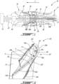
Figs. 1-2 , the high-pressure turbine 18a includes a rotor having acentral hub 29 and a peripheral array ofreplaceable turbine blades 30. Any of the rotors of any of the high-pressure turbine 18a and the low-pressure turbine 18b may include blades as will be described herein below. In the embodiment shown, the disclosedturbine blades 30 are part of the high-pressure turbine 18a, which, in the present case, includes a single rotor. - Referring more particularly to
Fig. 2 , theblade 30 has aplatform 31 exposed to theannular gaspath 26 and a root 32 (Fig. 3 ) protruding inwardly from theplatform 31. Theroot 32 is received within correspondingly shaped slots defined by the central hub 29 (Fig. 1 ) to hold theblade 30 while the rotor is rotating about the central axis 11. Theblade 30 has anairfoil 33 protruding from theplatform 31 away from theroot 32 along a span S. Theairfoil 33 has abase 33a at theplatform 31 and atip 33b radially spaced apart from theroot 33a relative to the central axis 11. Theairfoil 33 hence extends along a direction having a radial component relative to the central axis 11 from thebase 33a to thetip 33b. The airfoil 33 has a leadingedge 33c, atrailing edge 33d spaced apart from the leadingedge 33c by a chord C (Fig. 4 ), apressure side 33e and asuction side 33f opposed to thepressure side 33e. The pressure andsuction sides edge 33c to thetrailing edge 33d and from thebase 33a to thetip 33b. The chord C is depicted here as a straight line connecting theleading edge 33c to the trailingedge 33d. The chord C may vary along the span S of theairfoil 33 between thebase 33a and thetip 33b. The chord C differs from a camber line CL (Fig. 6 ), which corresponds to a line that may be curved and that connects theleading edge 33c to the trailingedge 33d and that is centered between the pressure and suctionssides tip 33b) between thebase 33a and thetip 33b. - The
blade 30 has a tip pocket, also referred to as tip plenum, 34 circumscribed by aperipheral tip wall 35. Theperipheral tip wall 35 defines a portion of thepressure side 33e and a portion of thesection side 33f. The blade has an end wall which defines abottom wall 36 of the tip plenum. Thebottom wall 36 extends from thepressure side 33e to thesuction side 33f. Thetip pocket 34 is therefore substantially bounded by theperipheral tip wall 35 and thebottom wall 36. Theblade 30 defines internal cooling passages 37 (only one cooling passage may be present) (Fig. 3 ) within theairfoil 33. Thecooling passages 37 havetip outlets tip pocket 34 andside outlets 37c located between thebase 33a and thetip 33b proximate the trailingedge 33d and through the pressure and/orsuction sides tip outlets tip outlets first tip outlet 37a proximate theleading edge 33c of theairfoil 33 and a plurality of second tip outlets located between thefirst tip outlet 37a and the trailingedge 33d. The first andsecond tip outlets leading edge 33c and the trailingedge 33d. Diameters of thesecond tip outlets 37b decrease from theleading edge 33c to the trailingedge 33d because of a distance between the pressure andsuction sides edge 33d. They may have a constant diameter. A density of thesecond tip outlets 37b may increase toward the trailingedge 33d to compensate for their smaller diameter. The cooling air may come from the compressor section 14 (Fig. 1 ) of thegas turbine engine 10. Many factors are involved in determining the position and size of the tip outlets: pressure distribution between the inside of the blade and the outside, the flow structure (orientation, etc) inside the blade, etc. - In use, the rotor of the high-pressure turbine 18a of the
turbine section 18 rotates at high speed about the central axis 11. The pressure of the combustion gases at thepressure side 33e of theairfoil 33 is greater than that at thesuction side 33f of theairfoil 33. This tends to induce a phenomenon known as "tip leakage" where the combustion gases tend to flow from thepressure side 33e to thesuction side 33f of theairfoil 33 around thetip 33b. This may impair efficiency of theturbine section 18 because theturbine section 18 is not able to extract as much energy from the combustion gases as it could if no tip leakage were present. To deter the combustion gases to flow around thetip 33b of theairfoil 33, theperipheral tip wall 35 is created. That is, theperipheral tip wall 35 has apressure side portion 35a and asuction side portion 35b spaced apart from thepressure side portion 35a by thepocket 34. The pressure andsuction sides portions peripheral tip wall 35 act as knife edges of a labyrinth seal and contributes in decreasing an amount of the combustion gases that flows within a gap between thetip 33b of theairfoil 33 and turbine shrouds circumferentially distributed around theblades 30 compared to a configuration in which thetip pocket 34 is absent. In other words, implementing thetip pocket 34 creates two knife edges, which corresponds here as the pressure andsuction sides portions peripheral tip wall 35. These pressure andsuction side portions peripheral tip wall 35 create a sealing engagement with the surrounding turbine shrouds. An amount of the combustion gases flowing from thepressure side 33e to thesuction side 33f around thetip 33b may therefore be decreased by the implementation of theperipheral tip wall 35 andtip pocket 34 for a constant tip clearance. - However, a thickness T1 of the
peripheral tip wall 35 may be quite small. In the embodiment shown, the thickness T1 is about 0.02 inch (0.05 cm). Some locations of theperipheral tip wall 35 are simultaneously exposed to the hot combustion gases flowing through theturbine section 18 and to the cooler cooling air from theinternal cooling passages 37 and exiting into thetip pocket 34. Hence, some locations of theperipheral tip wall 35 are subjected to strong temperature gradients. With time, these strong temperature gradients may expose theblade 30 to thermal mechanical fatigue (TMF) and may shorten the lifespan of theblades 30. Frequency of costly downtimes required to replace theblades 30 may therefore be increased. This may be undesired. - Moreover, if the
blade 30 is used into the high-pressure turbine 18a of theturbine section 18, it will be exposed to the hottest temperatures since the high-pressure turbine 18a is immediately downstream of thecombustor 16. In the embodiment shown, the high-pressure turbine 18a includes only a single rotor. Hence, the amount of work extracted from the combustion gases by the single rotor of the high-pressure turbine 18a is very high and, consequently, so are the temperature gradients theblades 30 of this single rotor are exposed to. This may enhance the TMF phenomenon described above. - The inventors of the present application noticed that some locations on the
peripheral tip wall 35 may be more susceptible than other to TMF. For instance, an area on thepressure side portions 35a of theperipheral tip wall 35 is located where high thermal flux are present. Thesuction side portion 35b of theperipheral tip wall 35 may be seen as being shielded. Moreover, it has been further observed by the inventors of the present application that portions of theperipheral tip wall 35 that are closest to the first andsecond tip outlet cooling passages 37 are more prone to high temperature gradients because the cooling air flowing within thepocket 34 is the coldest near the first andsecond tip outlets bottom wall 36. Moreover, the inventors of the present application observed that a location of theperipheral tip wall 35 aligned with a location L1 (Fig. 5 ) where a curvature of a concave portion of thepressure side 33e of theairfoil 33 is maximal may be more prone to TMF. More specifically, TMF and curvature are related to other blade mechanical stresses from rotational forces that may create bending, and global thermal effects. These stresses and thermal effects may be amplified by the higher curvature of the airfoil. This stress component may be a driver for TMF. - Referring to
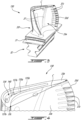
Figs. 3-6 , a blade in accordance with another embodiment is shown at 130. Theblade 130 may be used as part of the high-pressure turbine 18a of theturbine section 18 of theengine 10. Theblade 130 may be used in any of the rotors of theturbine section 18 of theengine 10. Features of theblade 130 that are described below may at least partially alleviate the aforementioned drawbacks. - The
blade 130 has atip pocket 134 bounded by aperipheral tip wall 135 and by abottom wall 136.Outlets 137a of thecooling passages 37 are defined through thebottom wall 136 to supply thetip pocket 134 with cooling air. In order to decrease the thermal gradients discussed above, a reinforcingbump 140 is defined by theperipheral tip wall 135. The reinforcingbump 140 locally increases a thickness of theperipheral tip wall 135. In other words, the reinforcingbump 140 corresponds to a section of theperipheral tip wall 135 having a greater thickness than a nominal thickness of theperipheral tip wall 135 on opposite sides of the reinforcingbump 140. This increase in thickness may allow to increase stiffness of theperipheral tip wall 135 and may allow to decrease thermal gradients therein because of the added material. - In the illustrated embodiment, the reinforcing
bump 140 extends from thepressure side portion 135a of theperipheral tip wall 135 into thetip pocket 134. The reinforcingbump 140 is located at the location L1 where high thermal flux are present on theblade 130 The location L1 is located on thepressure side 33e of theairfoil 33. As illustrated inFig. 5 , the reinforcingbump 140 is located between twofirst outlets 137a of thecooling passages 37. The twofirst outlets 137a are disposed linearly along the camber line CL of theairfoil 33. In the present embodiment, the twofirst outlets 137a are centered on the camber line CL. Diameters of the twofirst outlets 137a are substantially equal to one another. The twofirst outlets 137a are the first tip outlets of theblade 130 starting from theleading edge 33c toward the trailingedge 33d.Second tip outlets 37b (Fig. 2 ) are located between thefirst tip outlets 137a and the trailingedge 33d. As illustrated inFig. 6 , a chordwise position of a center of the reinforcingbump 140 is between chordwise positions of the first twotip outlets 137a starting from theleading edge 33c. In the depicted embodiment, the reinforcingbump 140 overlaps a location where a curvature of a concave portion of thepressure side 33e of the airfoil is maximal. - As illustrated in
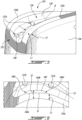
Figs. 5-6 , the reinforcingbump 140 protrudes from a baseline surface B of thepressure side portion 135a of theperipheral tip wall 135 from abump root 140a to abump end 140b. The reinforcingbump 140 may be made of a different material secured (i.e., welded) to theperipheral tip wall 35. The reinforcingbump 140 may be made of a welded element of the same material as a remainder of theblade 130 or of another compatible alloy. In the present case, the reinforcingbump 140 monolithically protrudes from the baseline surface B of theperipheral tip wall 35. As shown inFig. 6 , thebump end 140b is spaced apart from thesuction side portion 135b of theperipheral tip wall 135. That is, in the depicted embodiment, the reinforcingbump 140 does not extend fully across thetip pocket 134. In other words, thesuction side 33f of theairfoil 33 is free from direct connection to the reinforcingbump 140. - Particularly, in the illustrated embodiment, the reinforcing
bump 140 does not extend past the camber line CL of theairfoil 33 at thetip 33b. The twooutlets 137a may be substantially centered between the pressure andsuction sides bump 140 does not intersect an imaginary straight line connecting together the twooutlets 137a. - In the embodiment shown, a center of the reinforcing
bump 140 is located at from 15% to 25% of the chord C from theleading edge 33c. A width of the reinforcingbump 140 taken in a direction along the chord C from afore end 140c to arear end 140d is about 10% of the chord C. In the present case, the reinforcingbump 140 is located closer to theleading edge 33c than to the trailingedge 33d. The reinforcingbump 140 extends from thebottom wall 136 to thetip 33b of theairfoil 33. That is, a radial height of the reinforcingbump 140 is the same as that of theperipheral tip wall 135. - In the embodiment shown, the thickness T2 of the
peripheral tip wall 135 at the reinforcing bump 140 (more specifically, the thickness T2 of theperipheral tip wall 135 at thebump end 140b of the reinforcingbump 140 at an intermediate section between its fore andrear ends peripheral tip wall 135. The nominal thickness T1 may correspond to the thickness of theperipheral tip wall 135 on opposite sides of the reinforcingbump 140. Should theperipheral tip wall 135 on opposite sides of the reinforcingbump 140 comprise different thicknesses, the nominal thickness T1 corresponds to the greater of these two thicknesses. A ratio of the thickness T2 at the reinforcingbump 140 to the nominal thickness T1 is between about 1.5 and about 2.5. In the embodiment shown, the ratio of the thickness T2 at the reinforcingbump 140 to the nominal thickness T1 is 1.75. In the present case, the thickness T1 at the reinforcingbump 140 is about 0.035 inch (0.089 cm). - In the present case, the reinforcing
bump 140 includes solely one bump. That is, theblade 130 may be free from other bump. A thickness of theperipheral tip wall 135 may be substantially constant but for the reinforcingbump 140. In a particular embodiment, the tip wall thickness is .020 inch (0.05 cm) and may vary from 0.013 to 0.033 inch (0.033 to 0.084 cm). However, the thickness of the wall at the baseline surface B on which the reinforcingbump 140 is located may have a thickness of 0.02 inch (0.05 cm) plus or minus 0.003 inch (0.0076 cm). That is, the thickness of the wall at the baseline surface may range from 0.017 inch to 0.023 inch (0.043 cm to 0.058 cm). The reinforcingbump 140 may be 0.015 inch (0.038 cm) proud from the baseline surface B and may vary by plus or minus 0.006 inch (0.015 cm). That is, from 0.009 inch to 0.021 inch (0.023 cm to 0.053 cm). In a particular embodiment, a thickness of the reinforcingbump 140 may vary along its length. That is, the reinforcingbump 140 may be non uniform in thickness. - Referring now to
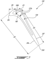
Fig. 7 , a ratio of a distance D1 between the first twotip outlets 137a to a distance D2 between a forward-most point of the tip of theblade 130 and the trailingedge 33d of the tip of theblade 130 may be about 0.10. A ratio of a distance D3 between a rearward-most one of the first twotip outlets 137a and the trailingedge 33d to the distance D2 between the forward-most point of the tip of theblade 130 and the trailingedge 33d is about 0.79. A ratio of a distance D4 between thefore end 140c of the reinforcingbump 140 and theleading edge 33c to the distance D2 between the forward-most point of the tip of theblade 130 and the trailingedge 33d is about 0.15. Herein, "about" imply a variation of plus or minus 10%. - The durability of the
blade 130 including theperipheral tip wall 135 may be increased by the reinforcingbump 140. The reinforcingbump 140, by protruding into thetip pocket 134, may avoid any change to the external airfoil geometry and with a negligible weight increase. Accordingly the thermo-mechanical fatigue life of theblade 130 may be addressed by addition of the reinforcingbump 140 in accordance with the example described above and shown in the drawings. - This present disclosure introduces a local thickening of the peripheral tip wall, which may reduce the thermal gradient and may reduce the nominal stress. This may lead to an improvement in TMF life at the location of the added thickness. Since the air inside the
tip pocket 134 is a resultant of tip leakage and core cooling air exhausted through the outlets of the cooling passages, and because of thermal conductivity, the wall surface temperature on the tip pocket side is lower than the wall surface temperature on the pressure side of the blade. The combination of environmental stresses and the stress caused by the described thermal difference results in high local stresses at specific locations along this wall. The increased thickness may spread the temperature difference over a larger area, and may allow for better conduction of heat out of that area. This may reduce the gradient and improve the TMF life. - In the present disclosure, the expression "about" means that a value may vary by 10% of the value. For instance, about 10 implies that the value varies from 9 to 11.
- The embodiments described in this document provide non-limiting examples of possible implementations of the present technology. Upon review of the present disclosure, a person of ordinary skill in the art will recognize that changes may be made to the embodiments described herein without departing from the scope of the present technology. Yet further modifications could be implemented by a person of ordinary skill in the art in view of the present disclosure, which modifications would be within the scope of the present technology.
Claims (13)
- A turbine blade (130) for a gas turbine engine (10), comprising:an airfoil (33) extending along a span (S) from a base (33a) to a tip (33b) and along a chord (C) from a leading edge (33c) to a trailing edge (33d), the airfoil (33) having a pressure side (33e) and a suction side (33f),a tip pocket (134) at the tip (33b) of the airfoil (33), the tip pocket (134) at least partially surrounded by a peripheral tip wall (135) defining a portion of the pressure and suction sides (33e, 33f);at least one internal cooling passage (37) in the airfoil, the at least one internal cooling passage (37) having at least one outlet (137a) communicating with the tip pocket (134); anda reinforcing bump (140) located on the pressure side (33e) of the airfoil (33) and protruding from a baseline surface (B) of the peripheral tip wall (135) to a bump end (140b) located into the tip pocket (134),characterized in the reinforcing bump (140) overlapping a location (L1) where a curvature of a concave portion of the pressure side (33e) of the airfoil (33) is maximal.
- The turbine blade (130) of claim 1, wherein a thickness (T2) of the peripheral tip wall (135) at the reinforcing bump (140) corresponds to a nominal thickness (T1) of the peripheral tip wall (135) at a location adjacent the reinforcing bump (140) plus a bump thickness of the reinforcing bump (140).
- The turbine blade (130) of claim 2, wherein a ratio of the thickness (T2) of the peripheral tip wall (135) at the reinforcing bump (140) to the nominal thickness of the peripheral tip wall (135) is between 1.5 and 2.5.
- The turbine blade (130) of claim 3, wherein the ratio of the thickness (T2) of the peripheral tip wall (135) at the reinforcing bump (140) to the nominal thickness (T1) of the peripheral tip wall (135) is about 1.75.
- The turbine blade (130) of any preceding claim, wherein the tip pocket (134) is bounded by the peripheral tip wall (135) and by a bottom wall (136), the bottom wall (136) extending from the pressure side (33e) to the suction side (33f), the reinforcing bump (140) extending from the bottom wall (136) to the tip (33b).
- The turbine blade (130) of any preceding claim, wherein a chordwise position of a center of the reinforcing bump (140) is between chordwise positions of two outlets (137a) of the at least one outlet (137a).
- The turbine blade (130) of any preceding claim, wherein a width of the reinforcing bump (140) taken in a direction along the chord (C) of the airfoil (33) is about 10% of the chord (C) of the airfoil (33).
- The turbine blade (130) of any preceding claim, wherein the reinforcing bump (140) is located closer to the leading edge (33c) than to the trailing edge (33d).
- The turbine blade (130) of claim 8, wherein a center of the reinforcing bump (140) is located at from 15% to 25% of the chord (C) from the leading edge (33c).
- The turbine blade (130) of any preceding claim, wherein the bump end (140b) is spaced apart from the suction side (33f).
- The turbine blade (130) of any preceding claim, wherein the bump end (140b) of the reinforcing bump (140) is closer to the baseline surface (B) than to the suction side (33f).
- A gas turbine engine (10), comprising a turbine section (18) having a rotor, the rotor having a central hub (29) and blades (30) secured to the central hub (29) and distributed about a central axis (11), each of the blades (30) comprising the turbine blade of any preceding claim, wherein:the peripheral tip wall (135) extends from a bottom wall (36) to the tip (33b) of the airfoil (33);the at least one internal cooling passage (37) is hydraulically connected to a source of a cooling fluid; andthe reinforcing bump (140) locally increases a thickness (T2) of the peripheral tip wall (135) beyond a nominal thickness (T1) of the peripheral tip wall (135), the reinforcing bump (140) ending into the tip pocket (135) and distanced from the leading edge (33c) by about 15% of the chord (C) or more.
- The gas turbine engine (10) of claim 12, wherein the turbine section (18) includes a high-pressure turbine (18A) and a low-pressure turbine (18B), the rotor being a single rotor of the high-pressure turbine (18A).
Applications Claiming Priority (1)
| Application Number | Priority Date | Filing Date | Title |
|---|---|---|---|
| US17/105,583 US11371359B2 (en) | 2020-11-26 | 2020-11-26 | Turbine blade for a gas turbine engine |
Publications (2)
| Publication Number | Publication Date |
|---|---|
| EP4006304A1 EP4006304A1 (en) | 2022-06-01 |
| EP4006304B1 true EP4006304B1 (en) | 2023-12-27 |
Family
ID=78806417
Family Applications (1)
| Application Number | Title | Priority Date | Filing Date |
|---|---|---|---|
| EP21210883.1A Active EP4006304B1 (en) | 2020-11-26 | 2021-11-26 | Turbine blade for a gas turbine engine and gas turbine engine |
Country Status (4)
| Country | Link |
|---|---|
| US (1) | US11371359B2 (en) |
| EP (1) | EP4006304B1 (en) |
| CA (1) | CA3139604A1 (en) |
| PL (1) | PL4006304T3 (en) |
Family Cites Families (134)
| Publication number | Priority date | Publication date | Assignee | Title |
|---|---|---|---|---|
| GB1188401A (en) | 1966-02-26 | 1970-04-15 | Gen Electric | Cooled Vane Structure for High Temperature Turbines |
| US3635585A (en) | 1969-12-23 | 1972-01-18 | Westinghouse Electric Corp | Gas-cooled turbine blade |
| US3781129A (en) | 1972-09-15 | 1973-12-25 | Gen Motors Corp | Cooled airfoil |
| US4010531A (en) | 1975-09-02 | 1977-03-08 | General Electric Company | Tip cap apparatus and method of installation |
| US4142824A (en) | 1977-09-02 | 1979-03-06 | General Electric Company | Tip cooling for turbine blades |
| US4390320A (en) | 1980-05-01 | 1983-06-28 | General Electric Company | Tip cap for a rotor blade and method of replacement |
| US4411597A (en) | 1981-03-20 | 1983-10-25 | The United States Of America As Represented By The Administrator Of The National Aeronautics And Space Administration | Tip cap for a rotor blade |
| US4606701A (en) | 1981-09-02 | 1986-08-19 | Westinghouse Electric Corp. | Tip structure for a cooled turbine rotor blade |
| US4424001A (en) | 1981-12-04 | 1984-01-03 | Westinghouse Electric Corp. | Tip structure for cooled turbine rotor blade |
| US4893987A (en) | 1987-12-08 | 1990-01-16 | General Electric Company | Diffusion-cooled blade tip cap |
| EP0340149B1 (en) | 1988-04-25 | 1993-05-19 | United Technologies Corporation | Dirt removal means for air cooled blades |
| JP3142850B2 (en) | 1989-03-13 | 2001-03-07 | 株式会社東芝 | Turbine cooling blades and combined power plants |
| US5660523A (en) | 1992-02-03 | 1997-08-26 | General Electric Company | Turbine blade squealer tip peripheral end wall with cooling passage arrangement |
| US5733102A (en) | 1996-12-17 | 1998-03-31 | General Electric Company | Slot cooled blade tip |
| JP3453268B2 (en) | 1997-03-04 | 2003-10-06 | 三菱重工業株式会社 | Gas turbine blades |
| WO2000019065A1 (en) | 1998-09-30 | 2000-04-06 | Siemens Aktiengesellschaft | Gas turbine moving blade and a method for producing a gas turbine moving blade |
| US6086328A (en) | 1998-12-21 | 2000-07-11 | General Electric Company | Tapered tip turbine blade |
| US6059530A (en) | 1998-12-21 | 2000-05-09 | General Electric Company | Twin rib turbine blade |
| US6224336B1 (en) | 1999-06-09 | 2001-05-01 | General Electric Company | Triple tip-rib airfoil |
| US6164914A (en) | 1999-08-23 | 2000-12-26 | General Electric Company | Cool tip blade |
| US6970005B2 (en) | 2000-08-24 | 2005-11-29 | Texas Instruments Incorporated | Multiple-chip probe and universal tester contact assemblage |
| JP2002213207A (en) | 2001-01-15 | 2002-07-31 | Mitsubishi Heavy Ind Ltd | Gas turbine segment |
| US6491496B2 (en) | 2001-02-23 | 2002-12-10 | General Electric Company | Turbine airfoil with metering plates for refresher holes |
| US6558119B2 (en) | 2001-05-29 | 2003-05-06 | General Electric Company | Turbine airfoil with separately formed tip and method for manufacture and repair thereof |
| US6527514B2 (en) | 2001-06-11 | 2003-03-04 | Alstom (Switzerland) Ltd | Turbine blade with rub tolerant cooling construction |
| US20030021684A1 (en) | 2001-07-24 | 2003-01-30 | Downs James P. | Turbine blade tip cooling construction |
| US6554575B2 (en) | 2001-09-27 | 2003-04-29 | General Electric Company | Ramped tip shelf blade |
| GB2382383B (en) | 2001-11-27 | 2005-09-21 | Rolls Royce Plc | Gas turbine engine aerofoil |
| DE10202810B4 (en) | 2002-01-25 | 2004-05-06 | Mtu Aero Engines Gmbh | Turbine rotor blade for the rotor of a gas turbine engine |
| DE60237350D1 (en) | 2002-05-09 | 2010-09-30 | Gen Electric | Turbine blade with triple backward winding cooling channels |
| US6652235B1 (en) | 2002-05-31 | 2003-11-25 | General Electric Company | Method and apparatus for reducing turbine blade tip region temperatures |
| US6672829B1 (en) | 2002-07-16 | 2004-01-06 | General Electric Company | Turbine blade having angled squealer tip |
| US6790005B2 (en) | 2002-12-30 | 2004-09-14 | General Electric Company | Compound tip notched blade |
| GB2402715B (en) | 2003-06-10 | 2006-06-14 | Rolls Royce Plc | Gas turbine aerofoil |
| DE102004002327A1 (en) | 2004-01-16 | 2005-08-04 | Alstom Technology Ltd | Cooled shovel for a gas turbine |
| DE502005008673D1 (en) | 2004-03-30 | 2010-01-21 | Alstom Technology Ltd | APPARATUS FOR COOLING AIR HOLDER OF A RUNNING BUCKET |
| US7029235B2 (en) | 2004-04-30 | 2006-04-18 | Siemens Westinghouse Power Corporation | Cooling system for a tip of a turbine blade |
| US7097419B2 (en) | 2004-07-26 | 2006-08-29 | General Electric Company | Common tip chamber blade |
| US7258528B2 (en) | 2004-12-02 | 2007-08-21 | Pratt & Whitney Canada Corp. | Internally cooled airfoil for a gas turbine engine and method |
| US7217088B2 (en) | 2005-02-02 | 2007-05-15 | Siemens Power Generation, Inc. | Cooling fluid preheating system for an airfoil in a turbine engine |
| US7458780B2 (en) | 2005-08-15 | 2008-12-02 | United Technologies Corporation | Hollow fan blade for gas turbine engine |
| DE502005003344D1 (en) | 2005-08-26 | 2008-04-30 | Siemens Ag | Hollow turbine blade |
| US7378324B2 (en) | 2006-03-30 | 2008-05-27 | International Business Machines Corporation | Selective links in silicon hetero-junction bipolar transistors using carbon doping and method of forming same |
| US7513743B2 (en) | 2006-05-02 | 2009-04-07 | Siemens Energy, Inc. | Turbine blade with wavy squealer tip rail |
| US7473073B1 (en) | 2006-06-14 | 2009-01-06 | Florida Turbine Technologies, Inc. | Turbine blade with cooled tip rail |
| US8632311B2 (en) | 2006-08-21 | 2014-01-21 | General Electric Company | Flared tip turbine blade |
| US7686578B2 (en) | 2006-08-21 | 2010-03-30 | General Electric Company | Conformal tip baffle airfoil |
| US8512003B2 (en) | 2006-08-21 | 2013-08-20 | General Electric Company | Tip ramp turbine blade |
| US8425183B2 (en) | 2006-11-20 | 2013-04-23 | General Electric Company | Triforial tip cavity airfoil |
| US7704047B2 (en) | 2006-11-21 | 2010-04-27 | Siemens Energy, Inc. | Cooling of turbine blade suction tip rail |
| US7704045B1 (en) | 2007-05-02 | 2010-04-27 | Florida Turbine Technologies, Inc. | Turbine blade with blade tip cooling notches |
| US8011889B1 (en) | 2007-09-07 | 2011-09-06 | Florida Turbine Technologies, Inc. | Turbine blade with trailing edge tip corner cooling |
| US7922451B1 (en) | 2007-09-07 | 2011-04-12 | Florida Turbine Technologies, Inc. | Turbine blade with blade tip cooling passages |
| US8047789B1 (en) | 2007-10-19 | 2011-11-01 | Florida Turbine Technologies, Inc. | Turbine airfoil |
| US7967563B1 (en) | 2007-11-19 | 2011-06-28 | Florida Turbine Technologies, Inc. | Turbine blade with tip section cooling channel |
| ES2442873T3 (en) | 2008-03-31 | 2014-02-14 | Alstom Technology Ltd | Aerodynamic gas turbine profile |
| FR2934008B1 (en) | 2008-07-21 | 2015-06-05 | Turbomeca | AUBE HOLLOW TURBINE WHEEL HAVING A RIB |
| US8469666B1 (en) | 2008-08-21 | 2013-06-25 | Florida Turbine Technologies, Inc. | Turbine blade tip portion with trenched cooling holes |
| US8061987B1 (en) | 2008-08-21 | 2011-11-22 | Florida Turbine Technologies, Inc. | Turbine blade with tip rail cooling |
| US8043058B1 (en) | 2008-08-21 | 2011-10-25 | Florida Turbine Technologies, Inc. | Turbine blade with curved tip cooling holes |
| US8113779B1 (en) | 2008-09-12 | 2012-02-14 | Florida Turbine Technologies, Inc. | Turbine blade with tip rail cooling and sealing |
| US7997865B1 (en) | 2008-09-18 | 2011-08-16 | Florida Turbine Technologies, Inc. | Turbine blade with tip rail cooling and sealing |
| CN102057134B (en) | 2008-10-30 | 2015-04-22 | 三菱日立电力系统株式会社 | Turbine moving blade having tip thinning |
| US8083484B2 (en) | 2008-12-26 | 2011-12-27 | General Electric Company | Turbine rotor blade tips that discourage cross-flow |
| US8096768B1 (en) | 2009-02-04 | 2012-01-17 | Florida Turbine Technologies, Inc. | Turbine blade with trailing edge impingement cooling |
| US8092179B2 (en) | 2009-03-12 | 2012-01-10 | United Technologies Corporation | Blade tip cooling groove |
| US8157504B2 (en) | 2009-04-17 | 2012-04-17 | General Electric Company | Rotor blades for turbine engines |
| GB0910177D0 (en) * | 2009-06-15 | 2009-07-29 | Rolls Royce Plc | A cooled component for a gas turbine engine |
| US20160052621A1 (en) | 2009-07-10 | 2016-02-25 | Peter Ireland | Energy efficiency improvements for turbomachinery |
| US8439643B2 (en) | 2009-08-20 | 2013-05-14 | General Electric Company | Biformal platform turbine blade |
| US8337158B1 (en) | 2009-10-22 | 2012-12-25 | Florida Turbine Technologies, Inc. | Turbine blade with tip cap |
| US8251660B1 (en) | 2009-10-26 | 2012-08-28 | Florida Turbine Technologies, Inc. | Turbine airfoil with near wall vortex cooling |
| US8435004B1 (en) | 2010-04-13 | 2013-05-07 | Florida Turbine Technologies, Inc. | Turbine blade with tip rail cooling |
| US8740567B2 (en) | 2010-07-26 | 2014-06-03 | United Technologies Corporation | Reverse cavity blade for a gas turbine engine |
| GB201100957D0 (en) | 2011-01-20 | 2011-03-02 | Rolls Royce Plc | Rotor blade |
| US8876458B2 (en) | 2011-01-25 | 2014-11-04 | United Technologies Corporation | Blade outer air seal assembly and support |
| CN102128055A (en) | 2011-04-21 | 2011-07-20 | 西北工业大学 | Gas turbine cooling blade with crown |
| US8801379B2 (en) | 2011-06-15 | 2014-08-12 | Honeywell International Inc. | Wheel and replaceable nose piece |
| US9322280B2 (en) | 2011-08-12 | 2016-04-26 | United Technologies Corporation | Method of measuring turbine blade tip erosion |
| CN104105842A (en) | 2011-12-29 | 2014-10-15 | 通用电气公司 | Airfoil cooling circuit |
| EP2798175A4 (en) | 2011-12-29 | 2017-08-02 | Rolls-Royce North American Technologies, Inc. | Gas turbine engine and turbine blade |
| US9228442B2 (en) | 2012-04-05 | 2016-01-05 | United Technologies Corporation | Turbine airfoil tip shelf and squealer pocket cooling |
| EP2844839A1 (en) | 2012-04-23 | 2015-03-11 | General Electric Company | Turbine airfoil with local wall thickness control |
| US9297262B2 (en) | 2012-05-24 | 2016-03-29 | General Electric Company | Cooling structures in the tips of turbine rotor blades |
| EP2666968B1 (en) | 2012-05-24 | 2021-08-18 | General Electric Company | Turbine rotor blade |
| US9188012B2 (en) | 2012-05-24 | 2015-11-17 | General Electric Company | Cooling structures in the tips of turbine rotor blades |
| US9470096B2 (en) | 2012-07-26 | 2016-10-18 | General Electric Company | Turbine bucket with notched squealer tip |
| US9045988B2 (en) | 2012-07-26 | 2015-06-02 | General Electric Company | Turbine bucket with squealer tip |
| US10408066B2 (en) | 2012-08-15 | 2019-09-10 | United Technologies Corporation | Suction side turbine blade tip cooling |
| US9115590B2 (en) | 2012-09-26 | 2015-08-25 | United Technologies Corporation | Gas turbine engine airfoil cooling circuit |
| US9995148B2 (en) | 2012-10-04 | 2018-06-12 | General Electric Company | Method and apparatus for cooling gas turbine and rotor blades |
| US9334742B2 (en) | 2012-10-05 | 2016-05-10 | General Electric Company | Rotor blade and method for cooling the rotor blade |
| EP2725195B1 (en) | 2012-10-26 | 2019-09-25 | Rolls-Royce plc | Turbine blade and corresponding rotor stage |
| US9057276B2 (en) | 2013-02-06 | 2015-06-16 | Siemens Aktiengesellschaft | Twisted gas turbine engine airfoil having a twisted rib |
| US9120144B2 (en) | 2013-02-06 | 2015-09-01 | Siemens Aktiengesellschaft | Casting core for twisted gas turbine engine airfoil having a twisted rib |
| EP2801702B1 (en) | 2013-05-10 | 2020-05-06 | Safran Aero Boosters SA | Inner shroud of turbomachine with abradable seal |
| US10487667B2 (en) | 2013-07-01 | 2019-11-26 | United Technologies Corporation | Airfoil, and method for manufacturing the same |
| US10352172B2 (en) | 2013-09-06 | 2019-07-16 | United Technologies Corporation | Manufacturing method for a dual wall component |
| US10487668B2 (en) | 2013-09-06 | 2019-11-26 | United Technologies Corporation | Gas turbine engine airfoil with wishbone baffle cooling scheme |
| US9856739B2 (en) | 2013-09-18 | 2018-01-02 | Honeywell International Inc. | Turbine blades with tip portions having converging cooling holes |
| WO2015061152A1 (en) | 2013-10-21 | 2015-04-30 | United Technologies Corporation | Incident tolerant turbine vane cooling |
| US9896943B2 (en) | 2014-05-12 | 2018-02-20 | Honeywell International Inc. | Gas path components of gas turbine engines and methods for cooling the same using porous medium cooling systems |
| US10012089B2 (en) * | 2014-05-16 | 2018-07-03 | United Technologies Corporation | Airfoil tip pocket with augmentation features |
| US20160341046A1 (en) | 2014-05-29 | 2016-11-24 | General Electric Company | Dust holes |
| JP6239163B2 (en) | 2014-06-17 | 2017-11-29 | シーメンス エナジー インコーポレイテッド | Turbine blade cooling system with leading edge impingement cooling system and adjacent wall impingement system |
| EP3167161A1 (en) | 2014-07-07 | 2017-05-17 | Siemens Aktiengesellschaft | Gas turbine blade squealer tip, corresponding manufacturing and cooling methods and gas turbine engine |
| JP6434145B2 (en) | 2014-11-11 | 2018-12-05 | シーメンス アクチエンゲゼルシヤフトSiemens Aktiengesellschaft | Turbine blade with axial tip cooling circuit |
| US10107108B2 (en) | 2015-04-29 | 2018-10-23 | General Electric Company | Rotor blade having a flared tip |
| US9951642B2 (en) | 2015-05-08 | 2018-04-24 | United Technologies Corporation | Intermittent grooved soft abradable material to reduce blade tip temperature |
| US10174620B2 (en) | 2015-10-15 | 2019-01-08 | General Electric Company | Turbine blade |
| US10364681B2 (en) | 2015-10-15 | 2019-07-30 | General Electric Company | Turbine blade |
| US10487664B2 (en) | 2015-11-09 | 2019-11-26 | General Electric Company | Additive manufacturing method for making holes bounded by thin walls in turbine components |
| US10350684B2 (en) | 2015-11-10 | 2019-07-16 | General Electric Company | Additive manufacturing method for making complex film holes |
| US10677066B2 (en) | 2015-11-23 | 2020-06-09 | United Technologies Corporation | Turbine blade with airfoil tip vortex control |
| US10370979B2 (en) | 2015-11-23 | 2019-08-06 | United Technologies Corporation | Baffle for a component of a gas turbine engine |
| US10253637B2 (en) | 2015-12-11 | 2019-04-09 | General Electric Company | Method and system for improving turbine blade performance |
| US10301945B2 (en) | 2015-12-18 | 2019-05-28 | General Electric Company | Interior cooling configurations in turbine rotor blades |
| US10053989B2 (en) | 2015-12-21 | 2018-08-21 | General Electric Company | Cooling circuit for a multi-wall blade |
| WO2017119898A1 (en) | 2016-01-08 | 2017-07-13 | Siemens Aktiengesellschaft | Turbine blade with multi-layer multi-height blade squealer |
| US10329922B2 (en) | 2016-02-09 | 2019-06-25 | General Electric Company | Gas turbine engine airfoil |
| US10184342B2 (en) | 2016-04-14 | 2019-01-22 | General Electric Company | System for cooling seal rails of tip shroud of turbine blade |
| US11021965B2 (en) | 2016-05-19 | 2021-06-01 | Honeywell International Inc. | Engine components with cooling holes having tailored metering and diffuser portions |
| US10801331B2 (en) * | 2016-06-07 | 2020-10-13 | Raytheon Technologies Corporation | Gas turbine engine rotor including squealer tip pocket |
| US10443401B2 (en) | 2016-09-02 | 2019-10-15 | United Technologies Corporation | Cooled turbine vane with alternately orientated film cooling hole rows |
| US10989056B2 (en) | 2016-12-05 | 2021-04-27 | Raytheon Technologies Corporation | Integrated squealer pocket tip and tip shelf with hybrid and tip flag core |
| US10815800B2 (en) | 2016-12-05 | 2020-10-27 | Raytheon Technologies Corporation | Radially diffused tip flag |
| US10436040B2 (en) | 2017-01-13 | 2019-10-08 | Rolls-Royce Corporation | Airfoil with dual-wall cooling for a gas turbine engine |
| WO2018143997A1 (en) | 2017-02-03 | 2018-08-09 | Siemens Aktiengesellschaft | Turbine blade |
| US10301943B2 (en) | 2017-06-30 | 2019-05-28 | General Electric Company | Turbomachine rotor blade |
| CN207048823U (en) | 2017-07-11 | 2018-02-27 | 江苏高群节能科技有限公司 | A kind of turbomachinery blade |
| EP3460190A1 (en) | 2017-09-21 | 2019-03-27 | Siemens Aktiengesellschaft | Heat transfer enhancement structures on in-line ribs of an aerofoil cavity of a gas turbine |
| US10378364B2 (en) | 2017-11-07 | 2019-08-13 | United Technologies Corporation | Modified structural truss for airfoils |
| US10570750B2 (en) | 2017-12-06 | 2020-02-25 | General Electric Company | Turbine component with tip rail cooling passage |
| US10655476B2 (en) | 2017-12-14 | 2020-05-19 | Honeywell International Inc. | Gas turbine engines with airfoils having improved dust tolerance |
-
2020
- 2020-11-26 US US17/105,583 patent/US11371359B2/en active Active
-
2021
- 2021-11-19 CA CA3139604A patent/CA3139604A1/en active Pending
- 2021-11-26 EP EP21210883.1A patent/EP4006304B1/en active Active
- 2021-11-26 PL PL21210883.1T patent/PL4006304T3/en unknown
Also Published As
| Publication number | Publication date |
|---|---|
| US20220162948A1 (en) | 2022-05-26 |
| US11371359B2 (en) | 2022-06-28 |
| PL4006304T3 (en) | 2024-04-15 |
| EP4006304A1 (en) | 2022-06-01 |
| CA3139604A1 (en) | 2022-05-26 |
Similar Documents
| Publication | Publication Date | Title |
|---|---|---|
| US10323534B2 (en) | Blade outer air seal with cooling features | |
| EP3187687B1 (en) | Midspan shrouded turbine rotor blades | |
| US10060272B2 (en) | Turbine vane with load shield | |
| US9476305B2 (en) | Impingement-cooled turbine rotor | |
| EP2653652B1 (en) | Axially-split radial turbine | |
| EP3473811B1 (en) | Fan blade platform | |
| US20190085705A1 (en) | Component for a turbine engine with a film-hole | |
| JP2019074077A5 (en) | A method of clearance control for interdigitated turbine engines. | |
| AU2007214378A1 (en) | Methods and apparatus for fabricating turbine engines | |
| US20090202355A1 (en) | Replaceable blade tip shroud | |
| EP1944468B1 (en) | A turbine blade | |
| CA2919845A1 (en) | Mounting apparatus for low-ductility turbine nozzle | |
| JP2016205390A (en) | Methods for positioning neighboring nozzles of gas turbine engine | |
| JP2016205390A5 (en) | ||
| US11927110B2 (en) | Component for a turbine engine with a cooling hole | |
| NL2002312C2 (en) | Cooled turbine nozzle segment. | |
| US20200049014A1 (en) | Turbine airfoil arrangement incorporating splitters | |
| US10760431B2 (en) | Component for a turbine engine with a cooling hole | |
| US10724380B2 (en) | CMC blade with internal support | |
| US20190024513A1 (en) | Shield for a turbine engine airfoil | |
| CN112523820A (en) | Turbine engine assembly | |
| EP4006304B1 (en) | Turbine blade for a gas turbine engine and gas turbine engine | |
| US11391161B2 (en) | Component for a turbine engine with a cooling hole | |
| EP3486496B1 (en) | Fan for gas turbine engines having mid-span shroud | |
| US11939880B1 (en) | Airfoil assembly with flow surface |
Legal Events
| Date | Code | Title | Description |
|---|---|---|---|
| PUAI | Public reference made under article 153(3) epc to a published international application that has entered the european phase |
Free format text: ORIGINAL CODE: 0009012 |
|
| STAA | Information on the status of an ep patent application or granted ep patent |
Free format text: STATUS: THE APPLICATION HAS BEEN PUBLISHED |
|
| AK | Designated contracting states |
Kind code of ref document: A1 Designated state(s): AL AT BE BG CH CY CZ DE DK EE ES FI FR GB GR HR HU IE IS IT LI LT LU LV MC MK MT NL NO PL PT RO RS SE SI SK SM TR |
|
| STAA | Information on the status of an ep patent application or granted ep patent |
Free format text: STATUS: REQUEST FOR EXAMINATION WAS MADE |
|
| 17P | Request for examination filed |
Effective date: 20221201 |
|
| RBV | Designated contracting states (corrected) |
Designated state(s): AL AT BE BG CH CY CZ DE DK EE ES FI FR GB GR HR HU IE IS IT LI LT LU LV MC MK MT NL NO PL PT RO RS SE SI SK SM TR |
|
| GRAJ | Information related to disapproval of communication of intention to grant by the applicant or resumption of examination proceedings by the epo deleted |
Free format text: ORIGINAL CODE: EPIDOSDIGR1 |
|
| GRAP | Despatch of communication of intention to grant a patent |
Free format text: ORIGINAL CODE: EPIDOSNIGR1 |
|
| GRAP | Despatch of communication of intention to grant a patent |
Free format text: ORIGINAL CODE: EPIDOSNIGR1 |
|
| STAA | Information on the status of an ep patent application or granted ep patent |
Free format text: STATUS: GRANT OF PATENT IS INTENDED |
|
| RIC1 | Information provided on ipc code assigned before grant |
Ipc: F01D 5/20 20060101AFI20230526BHEP |
|
| INTG | Intention to grant announced |
Effective date: 20230623 |
|
| GRAJ | Information related to disapproval of communication of intention to grant by the applicant or resumption of examination proceedings by the epo deleted |
Free format text: ORIGINAL CODE: EPIDOSDIGR1 |
|
| GRAP | Despatch of communication of intention to grant a patent |
Free format text: ORIGINAL CODE: EPIDOSNIGR1 |
|
| GRAS | Grant fee paid |
Free format text: ORIGINAL CODE: EPIDOSNIGR3 |
|
| INTG | Intention to grant announced |
Effective date: 20230623 |
|
| GRAA | (expected) grant |
Free format text: ORIGINAL CODE: 0009210 |
|
| STAA | Information on the status of an ep patent application or granted ep patent |
Free format text: STATUS: THE PATENT HAS BEEN GRANTED |
|
| AK | Designated contracting states |
Kind code of ref document: B1 Designated state(s): AL AT BE BG CH CY CZ DE DK EE ES FI FR GB GR HR HU IE IS IT LI LT LU LV MC MK MT NL NO PL PT RO RS SE SI SK SM TR |
|
| REG | Reference to a national code |
Ref country code: GB Ref legal event code: FG4D |
|
| REG | Reference to a national code |
Ref country code: CH Ref legal event code: EP |
|
| REG | Reference to a national code |
Ref country code: DE Ref legal event code: R096 Ref document number: 602021008086 Country of ref document: DE |
|
| REG | Reference to a national code |
Ref country code: IE Ref legal event code: FG4D |
|
| PG25 | Lapsed in a contracting state [announced via postgrant information from national office to epo] |
Ref country code: GR Free format text: LAPSE BECAUSE OF FAILURE TO SUBMIT A TRANSLATION OF THE DESCRIPTION OR TO PAY THE FEE WITHIN THE PRESCRIBED TIME-LIMIT Effective date: 20240328 |
|
| REG | Reference to a national code |
Ref country code: LT Ref legal event code: MG9D |
|
| PG25 | Lapsed in a contracting state [announced via postgrant information from national office to epo] |
Ref country code: LT Free format text: LAPSE BECAUSE OF FAILURE TO SUBMIT A TRANSLATION OF THE DESCRIPTION OR TO PAY THE FEE WITHIN THE PRESCRIBED TIME-LIMIT Effective date: 20231227 |