EP4006299B1 - Verfahren und system zur automatischen mehrzonenbohrlochprüfung mit geschlossener schleife eines reservoirs - Google Patents
Verfahren und system zur automatischen mehrzonenbohrlochprüfung mit geschlossener schleife eines reservoirs Download PDFInfo
- Publication number
- EP4006299B1 EP4006299B1 EP20306465.4A EP20306465A EP4006299B1 EP 4006299 B1 EP4006299 B1 EP 4006299B1 EP 20306465 A EP20306465 A EP 20306465A EP 4006299 B1 EP4006299 B1 EP 4006299B1
- Authority
- EP
- European Patent Office
- Prior art keywords
- fluid
- fluid flow
- zone
- wellbore
- upper zone
- Prior art date
- Legal status (The legal status is an assumption and is not a legal conclusion. Google has not performed a legal analysis and makes no representation as to the accuracy of the status listed.)
- Active
Links
Images




Classifications
-
- E—FIXED CONSTRUCTIONS
- E21—EARTH OR ROCK DRILLING; MINING
- E21B—EARTH OR ROCK DRILLING; OBTAINING OIL, GAS, WATER, SOLUBLE OR MELTABLE MATERIALS OR A SLURRY OF MINERALS FROM WELLS
- E21B49/00—Testing the nature of borehole walls; Formation testing; Methods or apparatus for obtaining samples of soil or well fluids, specially adapted to earth drilling or wells
- E21B49/008—Testing the nature of borehole walls; Formation testing; Methods or apparatus for obtaining samples of soil or well fluids, specially adapted to earth drilling or wells by injection test; by analysing pressure variations in an injection or production test, e.g. for estimating the skin factor
-
- E—FIXED CONSTRUCTIONS
- E21—EARTH OR ROCK DRILLING; MINING
- E21B—EARTH OR ROCK DRILLING; OBTAINING OIL, GAS, WATER, SOLUBLE OR MELTABLE MATERIALS OR A SLURRY OF MINERALS FROM WELLS
- E21B21/00—Methods or apparatus for flushing boreholes, e.g. by use of exhaust air from motor
- E21B21/10—Valve arrangements in drilling-fluid circulation systems
- E21B21/103—Down-hole by-pass valve arrangements, i.e. between the inside of the drill string and the annulus
-
- E—FIXED CONSTRUCTIONS
- E21—EARTH OR ROCK DRILLING; MINING
- E21B—EARTH OR ROCK DRILLING; OBTAINING OIL, GAS, WATER, SOLUBLE OR MELTABLE MATERIALS OR A SLURRY OF MINERALS FROM WELLS
- E21B33/00—Sealing or packing boreholes or wells
- E21B33/10—Sealing or packing boreholes or wells in the borehole
- E21B33/12—Packers; Plugs
- E21B33/122—Multiple string packers
-
- E—FIXED CONSTRUCTIONS
- E21—EARTH OR ROCK DRILLING; MINING
- E21B—EARTH OR ROCK DRILLING; OBTAINING OIL, GAS, WATER, SOLUBLE OR MELTABLE MATERIALS OR A SLURRY OF MINERALS FROM WELLS
- E21B33/00—Sealing or packing boreholes or wells
- E21B33/10—Sealing or packing boreholes or wells in the borehole
- E21B33/12—Packers; Plugs
- E21B33/124—Units with longitudinally-spaced plugs for isolating the intermediate space
-
- E—FIXED CONSTRUCTIONS
- E21—EARTH OR ROCK DRILLING; MINING
- E21B—EARTH OR ROCK DRILLING; OBTAINING OIL, GAS, WATER, SOLUBLE OR MELTABLE MATERIALS OR A SLURRY OF MINERALS FROM WELLS
- E21B34/00—Valve arrangements for boreholes or wells
- E21B34/06—Valve arrangements for boreholes or wells in wells
-
- E—FIXED CONSTRUCTIONS
- E21—EARTH OR ROCK DRILLING; MINING
- E21B—EARTH OR ROCK DRILLING; OBTAINING OIL, GAS, WATER, SOLUBLE OR MELTABLE MATERIALS OR A SLURRY OF MINERALS FROM WELLS
- E21B43/00—Methods or apparatus for obtaining oil, gas, water, soluble or meltable materials or a slurry of minerals from wells
- E21B43/12—Methods or apparatus for controlling the flow of the obtained fluid to or in wells
- E21B43/121—Lifting well fluids
- E21B43/128—Adaptation of pump systems with down-hole electric drives
-
- E—FIXED CONSTRUCTIONS
- E21—EARTH OR ROCK DRILLING; MINING
- E21B—EARTH OR ROCK DRILLING; OBTAINING OIL, GAS, WATER, SOLUBLE OR MELTABLE MATERIALS OR A SLURRY OF MINERALS FROM WELLS
- E21B47/00—Survey of boreholes or wells
- E21B47/06—Measuring temperature or pressure
-
- E—FIXED CONSTRUCTIONS
- E21—EARTH OR ROCK DRILLING; MINING
- E21B—EARTH OR ROCK DRILLING; OBTAINING OIL, GAS, WATER, SOLUBLE OR MELTABLE MATERIALS OR A SLURRY OF MINERALS FROM WELLS
- E21B47/00—Survey of boreholes or wells
- E21B47/12—Means for transmitting measuring-signals or control signals from the well to the surface, or from the surface to the well, e.g. for logging while drilling
- E21B47/14—Means for transmitting measuring-signals or control signals from the well to the surface, or from the surface to the well, e.g. for logging while drilling using acoustic waves
-
- E—FIXED CONSTRUCTIONS
- E21—EARTH OR ROCK DRILLING; MINING
- E21B—EARTH OR ROCK DRILLING; OBTAINING OIL, GAS, WATER, SOLUBLE OR MELTABLE MATERIALS OR A SLURRY OF MINERALS FROM WELLS
- E21B49/00—Testing the nature of borehole walls; Formation testing; Methods or apparatus for obtaining samples of soil or well fluids, specially adapted to earth drilling or wells
- E21B49/08—Obtaining fluid samples or testing fluids, in boreholes or wells
- E21B49/087—Well testing, e.g. testing for reservoir productivity or formation parameters
Definitions
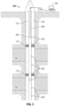
- the method further includes positioning the toolstring in the wellbore so that the first packer and the second packer straddle the upper zone, the first fluid valve and the second fluid valve straddle the upper zone, and the fluid flow device is adjacent the upper zone.
- the first packer is set to create a fluid flow barrier between the upper zone and an annulus of the wellbore surrounding the toolstring.
- the second packer is set to create a fluid flow barrier between the upper zone and the lower zone.
- the first fluid valve is closed to prevent a fluid flow through the toolstring to the surface, and the second fluid valve and the ports of the fluid flow device are opened to create a closed path for the hydrocarbon fluid to flow from the lower zone and into the upper zone.
- the method also includes perforating the lower zone.
- the method includes deploying a test string in a wellbore that extends from a surface and penetrates a hydrocarbon bearing formation that includes an upper zone and a lower zone.
- the test string includes a tubing, downhole tools to perform activities associated with a well test and acoustic repeaters coupled to the tubing and acoustically coupled with the downhole tools.
- the method further includes deploying a hub device in the wellbore that is communicatively coupled with surface equipment via a wired transmission medium and communicatively coupled with the acoustic repeaters via an acoustic transmission medium.
- the method also includes generating, by the hub device, commands directed to the downhole tools that cause the downhole tools to create a closed loop fluid flow path for hydrocarbon fluids to flow from the lower zone and into the upper zone during the well test.
- connection In the specification and appended claims: the terms “connect”, “connection”, “connected”, “in connection with”, and “connecting” are used to mean “in direct connection with” or “in connection with via one or more elements”; and the term “set” is used to mean “one element” or “more than one element”. Further, the terms “couple”, “coupling”, “coupled”, “coupled together”, and “coupled with” are used to mean “directly coupled together” or “coupled together via one or more elements”.
- hydrocarbon reservoirs and wells where two or more zones were discovered during drilling and formation testing from which hydrocarbons may be produced.
- the well operator decides to produce hydrocarbons from one zone at a time and plugs the other zones (e.g., the lower zones). Once the selected zone is depleted, the operator may desire to unplug the lower zones for testing.
- Well testing generally involves the process of recovering reservoir information based on pressure data collected by downhole sensors. Information that can be recovered includes skin, effective permeability and information concerning the geology and connectivity of boundary systems as they expand away from the wellbore.
- Information that can be recovered includes skin, effective permeability and information concerning the geology and connectivity of boundary systems as they expand away from the wellbore.
- One type of well test that is often performed is called a drill stem test (DST).
- DST drill stem test
- well testing provides valuable information for the operator, the testing can be costly in terms of the time and equipment needed.
- the fluids produced during the testing can create environmental concerns.
- a pressure disturbance is created that can be recorded by a gauge that is located either downhole (to measure bottom hole pressure or BHP) or at the surface (to measure well head pressure or WHP).
- This pressure disturbance can be created through a process where the hydrocarbon reservoir is produced (referred to as "drawdown") and then shut in (referred to as "buildup").
- drawdown the hydrocarbon reservoir is produced
- buildup shut in
- a typical well test may include multiple modes or phases, such as clean-up, initial build up, main flow and final build up.
- the reservoir is drawn down with the goal of cleaning the perforations and clearing the wellbore of any drilling or completion fluids.
- the build-up phases the well is shut in to increase the bottom hole pressure.
- the main flow phase the well fluid is drawn down by opening the well at a constant rate with the effect of decreasing the bottom hole pressure.
- Telemetry data obtained during the well test can provide information about both the well and the reservoir.
- the production index and skin can be derived for the interval of the well being tested, and the average/effective permeability, heterogeneities (fractures, layering, properties), shapes and distances of boundaries, and average and initial pressures can be derived for the reservoir.
- a conventional technique for actuating downhole tools and acquiring downhole data entails transmitting a single query directed to a specific target downhole and then waiting to receive a response from the target. This technique can be costly both in terms of speed and energy consumption.
- Multiple Hop Queries are directed to an efficient data harvesting technique, referred to here as "Multiple Hop Queries.”
- the hub repeater 204 assumes a supervisory (or master role) in the telemetry toolstring.
- Hub repeater 204 initiates a query that is composed of multiple simple queries, where each simple query is intended for a specific tool.
- a multiple hop query (“MHQ”) could include a "close tester valve” command directed to the tester valve 118, an "obtain pressure data" request directed to a sensor 124, 126, and an "open sleeve” command directed to the sliding sleeve device 122.
- the final repeater 202 compiles the responses into a final response message and directs the final response to the hub repeater 204.
- the hub repeater 204 then can transmit the final response to the surface acquisition equipment 146.
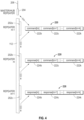
- FIG. 4 A simplified example of the MHQ harvesting technique is shown in Fig. 4 , in which the network 200 includes the master/hub repeater 204, repeater(m-1) 202a, repeater(m) 202b, repeater(m+1) 202c, and repeater(m+k) 202k (not shown), each coupled to an acoustic transmission medium, such as the tubing 112.
- the hub repeater 204 transmits an MHQ 220 that includes command(m) 222b, command(m+1) 222c, and command(m+k) 222k.
- Repeater(m-1) 202a receives the MHQ 220, verifies that the MHQ 220 does not include a command directed to it, and forward the MHQ 220 according to the routing algorithm.
- Repeater (m) 202b receives the MHQ 220, confirms that it includes a command(m) 222b directed to it, dequeues the MHQ 220 and processes the command(m) 222b, and then generates a response(m) 224b that it appends to the payload of the MHQ 220.
- MHQ 220 is then acoustically transmitted in accordance with the routing algorithm.
- Repeater(m+1) 202c receives MHQ 220, verifies that it includes a command(m+1) 222c, dequeues and processes the command(m+1) 222c, and then generates a response(m+1) 224c that it appends to the payload of MHQ 220.
- MHQ 220 is then acoustically transmitted in accordance with the routing algorithm. This process continues until the multiple hop query 220 (with the appended responses 224) reaches the final repeater(m+k) 202k. Repeater 202k compiles responses 224b-k into a message 226 that it then transmits back to the hub repeater 204.
- the MHQ technique illustrated in Fig. 4 can be used to implement well testing using the tool string 110 in Figs. 1 and 2 .
- Each of the components of the tool string 110 are interfaced to an acoustic telemetry network, such as the network 200 shown in Fig. 3 .
- a set of operation modes can be predefined that correspond to each phase of the well test.
- a set of known tasks will be performed that can be translated into an MHQ.
- the phases of a drill stem test can correspond to a Pre-Perforation Mode, a Flowing Mode, a Build-Up Mode, and a Well Killing (Bullheading) Mode, among others.
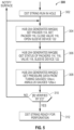
- Fig. 5 illustrates a workflow 300 for an exemplary Pre-Perforation Mode.
- the DST string 110 and the hub repeater 204 have been run in the wellbore 102.
- the hub repeater 204 generates and transmits on the acoustic telemetry network 200 an MHQ[A] that includes commands to "set packer 114," “set packer 116,” “close tester valve 118" and "open sliding sleeve device 120".
- the hub repeater 204 generates and transmits an MHQ[B] that includes queries to get the status of packers 114 and 116, tester valve 118 and sliding sleeve device 122.
- the hub repeater 204 generates and transmits an MHQ[C] that includes queries to get the pressure data from annulus gauge 126a, tubing gauge 124a, annulus gauge 126b, tubing gauge 124b, annulus gauge 126c and tubing gauge 124c.
- the hub repeater 204 examines the responses received from MHQ[B] and MHQ[C] to determine whether the pressure data confirms the status of the tools. If the status is not confirmed, the hub repeater 204 sends a notification message to the surface equipment 146 and re-starts the process at block 304. If the status is confirmed, then the DST string 110 is ready to perform perforation of lower zone 108 (block 312), and the perforation guns (not shown) can be activated.
- the next phase of the DST test corresponds to the Build-Up Mode, in which the lower zone 108 is shut in so that the bottom hole pressure can build up.
- An exemplary workflow 400 for the Build-Up Mode is illustrated in Fig. 6 .
- the hub repeater 204 After perforation of lower zone 108 and any cleanup is complete (block 402), the hub repeater 204 generates and transmits MHQ[B] and MHQ[C] in order to obtain the status of the various tools and the pressure data from the various gauges 124a-c, 126a-c (block 404).
- the hub repeater 204 compares the responses received in response to the MHQ[B] and MHQ[C] to determine whether the pressure data confirms the status of the tools. If the status is not confirmed, the hub repeater 204 notifies the surface equipment 146 and re-starts the process at block 404. If the status is confirmed, then the DST test is ready to build up the bottom hole pressure (block 408).
- the hub repeater 204 generates an MHQ[D] with multiple commands, including to close tester valve 120 and to change the rate at which pressure data is acquired from tubing gauge 124c and annulus gauge 126c.
- the MHQ[D] may command the tubing and annulus gauges 124c, 126c to provide pressure data at a fast rate (e.g., 1 second) for an initial short interval of the build-up phase (e.g., 10 minutes), a slower rate (e.g., 10 seconds) for a second interval (e.g., 1 hour), and then a much slower rate (e.g., 2 minutes) during the remainder of the pressure build-up period (e.g., 3 hours).
- a fast rate e.g. 1 second
- an initial short interval of the build-up phase e.g. 10 minutes
- a slower rate e.g. 10 seconds
- a second interval e.g., 1 hour
- a much slower rate e.g., 2 minutes
- the next phase of the DST test corresponds to the Flow Mode.
- the adjustable downhole choke 130 is set to a particular size and the tester valve 120 is opened so that fluid can flow from lower zone 108 and into upper zone 106 through the slidable sleeve device 122.
- the hub repeater 204 again generates MHQs to query the status of the downhole tools and to obtain pressure and/or flow data.
- the MHQs can include commands to vary the size of the choke 130 and, if desired, to acquire fluid samples.
- the DST test proceeds to the Kill Well Mode.
- the hub repeater 204 generates an MHQ with multiple commands, such as "open tester valve 120,” “wait 30 seconds,” “open tester valve 118,” “wait 30 seconds,” “open sliding sleeve 122,” “wait 30 seconds,” and “open choke 130 fully.”
- the hub repeater 204 can then generates an MHQ requesting the status of each of the tools to which the commands were sent.
- Hub repeater 204 can also generate an MHQ requesting pressure data from each of the gauges. If the pressure data confirms the status of the tools, then bullheading can be started to kill the well. Otherwise, the hub repeater 204 notifies the surface equipment 146 and re-starts the Kill Well Mode process.
- the DST test (or any other well test) described above can be performed automatically (i.e., without user intervention).
- the surface system 146 can send an executable file to the hub repeater 204 that contains the well test program, with details of the various modes, including the durations and the mode parameters.
- the hub repeater 204 can then execute the program, including generating an MHQ to activate the tools required for each particular phase of a mode. Once the tools for the current phase or mode are activated, the hub repeater 204 can generate MHQs to obtain tool status and acquire telemetry data. Data obtained by the hub repeater 204 can then be sent to the surface system 146 for display and real-time interpretation.
- the automatic mode can be interrupted by the well test operator.
- an operator can interrupt the well test at any time and send a specific acoustic command to a specific downhole tool.
- the interruption can be for verification, program changes, troubleshooting or any other purpose.
- the interruption mode can be temporary or permanent (i.e., cancelling the automatic execution of the well test program). If permanent, a new well test program can then be transmitted to the hub repeater 204 for execution.
- the techniques can be used with other types of well tests or operations. Further, the test may include different or additional phases or modes than those described above, and the various actions taken in each phase can be different than those described above or may be performed in different orders. Yet further, it should be understood that the closed loop well test technique can be implemented using communication networks other than the acoustic communications network 200. Still further, it should be further understood that the techniques described herein can be implemented in a variety of wireless communications systems, and that the physical layer of the communication is not limited to the acoustic telemetry system that has been described above.
Landscapes
- Engineering & Computer Science (AREA)
- Life Sciences & Earth Sciences (AREA)
- Mining & Mineral Resources (AREA)
- Geology (AREA)
- Physics & Mathematics (AREA)
- General Life Sciences & Earth Sciences (AREA)
- Environmental & Geological Engineering (AREA)
- Fluid Mechanics (AREA)
- Geochemistry & Mineralogy (AREA)
- Geophysics (AREA)
- Remote Sensing (AREA)
- Acoustics & Sound (AREA)
- Mechanical Engineering (AREA)
- Chemical & Material Sciences (AREA)
- Analytical Chemistry (AREA)
- Arrangements For Transmission Of Measured Signals (AREA)
- Testing Of Devices, Machine Parts, Or Other Structures Thereof (AREA)
- Automatic Analysis And Handling Materials Therefor (AREA)
- Measuring Fluid Pressure (AREA)
- Testing Or Calibration Of Command Recording Devices (AREA)
Claims (11)
- Verfahren (300, 400) zum Durchführen eines Bohrgestängetests in einem Bohrloch (102), umfassend:
Einführen (302) eines Werkzeugstrangs (110) in das Bohrloch (102), das sich von einer Oberfläche aus erstreckt und eine kohlenwasserstoffhaltige Formation durchdringt, wobei die Formation eine obere Zone (106), die an Kohlenwasserstofffluid verarmt oder trocken ist, und eine untere Zone (108), die ein Kohlenwasserstofffluid enthält, einschließt, wobei der Werkzeugstrang (110) eine Vielzahl von Werkzeugen zum Durchführen des Bohrgestängetests im Bohrloch (102) einschließt, wobei die Werkzeuge einschließen:einen ersten Packer (114) und einen zweiten Packer (116);ein erstes Fluidventil (118) und ein zweites Fluidventil (120) undeine Fluidströmungsvorrichtung, wobei die Fluidströmungsvorrichtung ein zylindrisches Gehäuse (140) einschließt, das eine Wand, die einen inneren Durchgang (139) für eine axiale Fluidströmung durch das Gehäuse (140) definiert, und eine Vielzahl von Anschlüssen (142) aufweist, die sich durch die Wand erstrecken, um einen Weg für eine radiale Fluidströmung bereitzustellen, die durch den inneren Durchgang (139) austritt, wenn die Anschlüsse (142) geöffnet sind;Positionieren des Werkzeugstrangs (110) im Bohrloch, sodass der erste Packer (114) und der zweite Packer (116) die obere Zone (106) überspannen, wobei das erste Fluidventil (118) und das zweite Fluidventil (120) die obere Zone (106) überspannen und die Fluidströmungsvorrichtung neben der oberen Zone (106) liegt;Einstellen (304) des ersten Packers (114), um eine Fluidströmungsbarriere zwischen der oberen Zone (106) und einem Ringraum (128) des Bohrlochs (102), der den Werkzeugstrang (110) umgibt, zu erzeugen;Einstellen (304) des zweiten Packers (116), um eine Fluidströmungsbarriere zwischen der oberen Zone (106) und der unteren Zone (108) zu erzeugen;Schließen (304) des ersten Fluidventils (118), um eine Fluidströmung durch den Werkzeugstrang (110) zur Oberfläche zu verhindern;Öffnen (304) des zweiten Fluidventils (120) und der Anschlüsse (142) der Fluidströmungsvorrichtung, um einen geschlossenen Pfad für das Kohlenwasserstofffluid zu erzeugen, damit dies von der unteren Zone (108) und in die obere Zone (106) strömt; undPerforieren der unteren Zone (108),wobei der Werkzeugstrang (110) während des Bohrgestängetests in einer Vielzahl von Modi betrieben wird, einschließlich eines Vorperforationsmodus, in dem der Status der Werkzeuge überprüft wird (306), eines Fluidströmungsmodus, in dem Fluid von der unteren Zone in die obere Zone strömt, und eines Aufbaumodus (400), in dem Fluiddruck im Bohrloch aufgebaut wird. - Verfahren (300, 400) nach Anspruch 1, ferner umfassend das Einsetzen eines akustischen Kommunikationsnetzwerks (200) in dem Bohrloch (102), wobei das Netzwerk (200) einen Hub-Repeater (204) einschließt, der über eine verdrahtete Verbindung (206) mit einem Oberflächensystem verbunden ist, und eine Vielzahl von akustischen Repeatern (202), die in beabstandeten Abständen mit der Rohrleitung (112) verbunden sind, wobei die akustischen Repeater (202) unter Verwendung der Rohrleitung (112) als elastisches Kommunikationsmedium kommunizieren.
- Verfahren (300, 400) nach Anspruch 2, wobei der Hub-Repeater (204) ein Verarbeitungssystem und eine Speicherungsvorrichtung umfasst, die Anweisungen in Verbindung mit dem Bohrlochtest enthält, die vom Verarbeitungssystem ausführbar sind, und wobei das Verfahren ferner automatisches Ausführen der Anweisungen zum Durchführen des Bohrlochtests umfasst.
- Verfahren (300, 400) nach Anspruch 3, wobei das Ausführen der Anweisung das Generieren einer Mehrfach-Hop-Abfrage (220) durch den Hub-Repeater (204) einschließt, einschließlich einer Vielzahl von Abfragen (222b, 222c, ..., 222k), die an eine Vielzahl unterschiedlicher Werkzeuge im Werkzeugstrang gerichtet ist.
- System (100) zum Durchführen eines Bohrgestängetests in einem Bohrloch (102), umfassend:eine Hub-Vorrichtung (204) zum Steuern und Überwachen des Bohrgestängetests im Bohrloch (102), das sich von einer Oberfläche aus erstreckt und eine Kohlenwasserstoffformation durchdringt, die eine obere Zone (106), die an Kohlenwasserstofffluid verarmt oder trocken ist, und eine untere Zone (108), die ein Kohlenwasserstofffluid enthält, aufweist; undeinen Werkzeugstrang (110), umfassend eine Vielzahl von Bohrlochwerkzeugen zum Durchführen von Aktionen, die mit dem Bohrgestängetest verknüpft sind, wobei die Werkzeuge einschließen:einen ersten Packer (114) und einen zweiten Packer (116), die zum Überspannen der oberen Zone (106) konfiguriert sind, wobei der erste Packer (114) konfiguriert ist, um eine Fluidströmungsbarriere zwischen der oberen Zone (106) und einem Ringraum (128) des Bohrlochs (102), der den Werkzeugstrang (110) umgibt, zu erzeugen, und wobei der zweite Packer (116) konfiguriert ist, um eine Fluidströmungsbarriere zwischen der oberen Zone (106) und der unteren Zone (108) zu erzeugen;ein erstes Fluidventil (118) und ein zweites Fluidventil (120), die zum Überspannen der oberen Zone (106) konfiguriert sind; undeine Fluidströmungsvorrichtung, die zum Positionieren neben der oberen Zone (106) konfiguriert ist, wobei die Fluidströmungsvorrichtung ein zylindrisches Gehäuse (140) einschließt, das eine Wand, die einen inneren Durchgang (139) für eine axiale Fluidströmung durch das Gehäuse (140) definiert, und eine Vielzahl von Anschlüssen (142) aufweist, die sich durch die Wand erstrecken, um einen Weg für eine radiale Fluidströmung bereitzustellen, die durch den inneren Durchgang (139) austritt, wenn die Anschlüsse (142) geöffnet sind;wobei die Hub-Vorrichtung (204) konfiguriert ist, um ein Steuersignal bereitzustellen zum:Schließen (304) des ersten Fluidventils (118), um eine Fluidströmung durch den Werkzeugstrang (110) zur Oberfläche zu verhindern;Öffnen (304) des zweiten Fluidventils (120) und der Anschlüsse (142) der Fluidströmungsvorrichtung, um einen geschlossenen Pfad für das Kohlenwasserstofffluid zu erzeugen, damit dies von der unteren Zone (108) und in die obere Zone (106) strömt; undPerforieren der unteren Zone (108), undwobei der Werkzeugstrang (110) während des Bohrgestängetests in einer Vielzahl von Modi betrieben wird, einschließlich eines Vorperforationsmodus, in dem der Status der Werkzeuge überprüft wird (306), eines Fluidströmungsmodus, in dem Fluid von der unteren Zone in die obere Zone strömt, und eines Aufbaumodus (400), in dem Fluiddruck im Bohrloch aufgebaut wird.
- System (100) nach Anspruch 5, ferner umfassend:eine Vielzahl von drahtlosen Repeatern (202), die kommunikativ mit einem drahtlosen Übertragungsmedium gekoppelt sind, das sich zwischen der Hub-Vorrichtung (204) und den Bohrlochwerkzeugen erstreckt, wobei die Vielzahl von drahtlosen Repeatern (202) konfiguriert ist, um mit den jeweiligen Bohrlochwerkzeugen zu kommunizieren und auf eine von der Hub-Vorrichtung generierte Mehrfach-Hop-Abfrage (220) zu antworten, wobei die Mehrfach-Hop-Abfrage (220) eine Vielzahl von Befehlen (222b, 222c, ..., 222k) einschließt, die an angepeilte Bohrlochwerkzeuge der Vielzahl von Bohrlochwerkzeugen gerichtet sind,wobei die Hub-Vorrichtung (204) konfiguriert ist, um eine Mehrfach-Hop-Abfrage (220) zu generieren, die die angepeilten Bohrlochwerkzeuge anleitet, während des Bohrgestängetests den geschlossenen Pfad zu erzeugen.
- System (100) nach Anspruch 6, wobei die Vielzahl von drahtlosen Repeatern (202) akustische Repeater (202) sind und wobei das drahtlose Übertragungsmedium eine Rohrleitung (112) eines Werkzeugstrangs (110) umfasst, der im Bohrloch eingesetzt wird, um den Bohrgestängetest durchzuführen.
- System (100) nach Anspruch 7, wobei die Hub-Vorrichtung (204) über einen verdrahteten Übertragungspfad (206) mit einem Oberflächensystem (146) kommunikativ gekoppelt ist und wobei die Hub-Vorrichtung (204) über einen akustischen Übertragungspfad (200) mit der Vielzahl von akustischen Repeatern (202) kommunikativ gekoppelt ist.
- System (100) nach Anspruch 5, wobei der Bohrgestängetest eine Vielzahl von Phasen einschließt, wobei jede Phase einem Betriebsmodus der Bohrloch-Strömungssteuerungswerkzeuge entspricht, und wobei die Hub-Vorrichtung (204) konfiguriert ist, um automatisch eine Mehrfach-Hop-Abfrage (220) zu generieren, um den Betriebsmodus der Bohrloch-Strömungssteuerungswerkzeuge während jeder Phase des Bohrlochtests zu steuern.
- System (100) nach Anspruch 5, wobei die Fluidströmungssteuervorrichtung ferner eine verschiebbare Hülse (138) umfasst, die relativ zum zylindrischen Gehäuse (140) verschiebbar ist, um die Anschlüsse (142) zu öffnen und zu schließen.
- System (100) nach Anspruch 10, wobei die verschiebbare Hülse (138) akustisch aktiviert wird.
Priority Applications (8)
| Application Number | Priority Date | Filing Date | Title |
|---|---|---|---|
| EP20306465.4A EP4006299B1 (de) | 2020-11-30 | 2020-11-30 | Verfahren und system zur automatischen mehrzonenbohrlochprüfung mit geschlossener schleife eines reservoirs |
| PCT/US2021/061133 WO2022115758A1 (en) | 2020-11-30 | 2021-11-30 | Method and system for automated multi-zone downhole closed loop reservoir testing |
| MX2023006302A MX2023006302A (es) | 2020-11-30 | 2021-11-30 | Método y sistema para la evaluación de yacimientos de circuito cerrado en el interior de pozos de carácter multizonal y automatizado. |
| IL303185A IL303185A (en) | 2020-11-30 | 2021-11-30 | Method and system for mechanized multi-zone closed-loop in-hole reservoir testing |
| US18/254,240 US12098633B2 (en) | 2020-11-30 | 2021-11-30 | Method and system for automated multi-zone downhole closed loop reservoir testing |
| EP21899211.3A EP4251848A4 (de) | 2020-11-30 | 2021-11-30 | Verfahren und system zur automatisierten mehrzonenbohrlochprüfung mit geschlossenem regelkreis |
| AU2021385448A AU2021385448A1 (en) | 2020-11-30 | 2021-11-30 | Method and system for automated multi-zone downhole closed loop reservoir testing |
| US18/815,108 US12448887B2 (en) | 2020-11-30 | 2024-08-26 | Method and system for automated multi-zone downhole closed loop reservoir testing |
Applications Claiming Priority (1)
| Application Number | Priority Date | Filing Date | Title |
|---|---|---|---|
| EP20306465.4A EP4006299B1 (de) | 2020-11-30 | 2020-11-30 | Verfahren und system zur automatischen mehrzonenbohrlochprüfung mit geschlossener schleife eines reservoirs |
Publications (2)
| Publication Number | Publication Date |
|---|---|
| EP4006299A1 EP4006299A1 (de) | 2022-06-01 |
| EP4006299B1 true EP4006299B1 (de) | 2025-07-09 |
Family
ID=73838993
Family Applications (2)
| Application Number | Title | Priority Date | Filing Date |
|---|---|---|---|
| EP20306465.4A Active EP4006299B1 (de) | 2020-11-30 | 2020-11-30 | Verfahren und system zur automatischen mehrzonenbohrlochprüfung mit geschlossener schleife eines reservoirs |
| EP21899211.3A Pending EP4251848A4 (de) | 2020-11-30 | 2021-11-30 | Verfahren und system zur automatisierten mehrzonenbohrlochprüfung mit geschlossenem regelkreis |
Family Applications After (1)
| Application Number | Title | Priority Date | Filing Date |
|---|---|---|---|
| EP21899211.3A Pending EP4251848A4 (de) | 2020-11-30 | 2021-11-30 | Verfahren und system zur automatisierten mehrzonenbohrlochprüfung mit geschlossenem regelkreis |
Country Status (6)
| Country | Link |
|---|---|
| US (2) | US12098633B2 (de) |
| EP (2) | EP4006299B1 (de) |
| AU (1) | AU2021385448A1 (de) |
| IL (1) | IL303185A (de) |
| MX (1) | MX2023006302A (de) |
| WO (1) | WO2022115758A1 (de) |
Families Citing this family (7)
| Publication number | Priority date | Publication date | Assignee | Title |
|---|---|---|---|---|
| EP4006299B1 (de) * | 2020-11-30 | 2025-07-09 | Services Pétroliers Schlumberger | Verfahren und system zur automatischen mehrzonenbohrlochprüfung mit geschlossener schleife eines reservoirs |
| NO347602B1 (en) | 2021-12-23 | 2024-01-29 | Testall As | Intelligent well testing system |
| EP4390056B1 (de) * | 2022-12-20 | 2026-02-25 | Services Pétroliers Schlumberger | Bohrlochprüfung mit geschlossener kammer |
| US12428960B2 (en) | 2023-10-09 | 2025-09-30 | Schlumberger Technology Corporation | Systems and methods for well testing |
| USD1110668S1 (en) * | 2024-03-01 | 2026-01-27 | Brady Worldwide, Inc. | Housing for an electric vehicle lockout device |
| CN117868803A (zh) * | 2024-03-13 | 2024-04-12 | 中石化西南石油工程有限公司 | 一种适用于超深井油气井的四联作测试管柱及其使用方法 |
| WO2025264661A1 (en) * | 2024-06-17 | 2025-12-26 | Schlumberger Technology Corporation | Method to mitigate wellbore instabilities |
Family Cites Families (61)
| Publication number | Priority date | Publication date | Assignee | Title |
|---|---|---|---|---|
| US3170520A (en) * | 1962-08-28 | 1965-02-23 | Reda Pump Company | Dual-flow transfer assembly |
| US3679264A (en) * | 1969-10-22 | 1972-07-25 | Allen T Van Huisen | Geothermal in situ mining and retorting system |
| US5335732A (en) * | 1992-12-29 | 1994-08-09 | Mcintyre Jack W | Oil recovery combined with injection of produced water |
| US5887652A (en) | 1997-08-04 | 1999-03-30 | Halliburton Energy Services, Inc. | Method and apparatus for bottom-hole testing in open-hole wells |
| US6325146B1 (en) | 1999-03-31 | 2001-12-04 | Halliburton Energy Services, Inc. | Methods of downhole testing subterranean formations and associated apparatus therefor |
| US6357525B1 (en) | 1999-04-22 | 2002-03-19 | Schlumberger Technology Corporation | Method and apparatus for testing a well |
| US6330913B1 (en) | 1999-04-22 | 2001-12-18 | Schlumberger Technology Corporation | Method and apparatus for testing a well |
| US6543540B2 (en) * | 2000-01-06 | 2003-04-08 | Baker Hughes Incorporated | Method and apparatus for downhole production zone |
| US6598682B2 (en) | 2000-03-02 | 2003-07-29 | Schlumberger Technology Corp. | Reservoir communication with a wellbore |
| NO312689B1 (no) * | 2000-09-05 | 2002-06-17 | Bjoern Dybdahl | Fremgangsmåte og anordning for brönntesting |
| US7100687B2 (en) | 2003-11-17 | 2006-09-05 | Cdx Gas, Llc | Multi-purpose well bores and method for accessing a subterranean zone from the surface |
| AU2006232093B2 (en) * | 2005-04-05 | 2012-02-02 | Big Cat Energy Corporation | Well bore fluid redistribution and fluid disposal |
| US7478555B2 (en) | 2005-08-25 | 2009-01-20 | Schlumberger Technology Corporation | Technique and apparatus for use in well testing |
| US8620636B2 (en) | 2005-08-25 | 2013-12-31 | Schlumberger Technology Corporation | Interpreting well test measurements |
| US20080149349A1 (en) | 2006-12-20 | 2008-06-26 | Stephane Hiron | Integrated flow control device and isolation element |
| US20090288824A1 (en) * | 2007-06-11 | 2009-11-26 | Halliburton Energy Services, Inc. | Multi-zone formation fluid evaluation system and method for use of same |
| MX2010005562A (es) * | 2007-11-30 | 2010-06-02 | Schlumberger Technology Bv | Sistema de prueba de zonas multiples de fondo de pozo, de un solo viaje, y metodo de prueba de fondo de pozo que utiliza dicho sistema. |
| US7921714B2 (en) * | 2008-05-02 | 2011-04-12 | Schlumberger Technology Corporation | Annular region evaluation in sequestration wells |
| EP2157279A1 (de) | 2008-08-22 | 2010-02-24 | Schlumberger Holdings Limited | Sender- und Empfänger-Synchronisation zur Herstellung drahtloser Telemetriesysteme |
| US20120250461A1 (en) | 2011-03-30 | 2012-10-04 | Guillaume Millot | Transmitter and receiver synchronization for wireless telemetry systems |
| EP2157278A1 (de) * | 2008-08-22 | 2010-02-24 | Schlumberger Holdings Limited | Drahtlose Telemetriesysteme für Bohrlochwerkzeuge |
| US8191416B2 (en) | 2008-11-24 | 2012-06-05 | Schlumberger Technology Corporation | Instrumented formation tester for injecting and monitoring of fluids |
| US8570832B2 (en) | 2008-12-31 | 2013-10-29 | Schlumberger Technology Corporation | Variable throat venturi flow meter having a plurality of section-varying elements |
| EP2464824B1 (de) | 2009-08-14 | 2018-10-03 | BP Corporation North America Inc. | Reservoirarchitektur und konnektivitätsanalyse |
| EP2317073B1 (de) * | 2009-10-29 | 2014-01-22 | Services Pétroliers Schlumberger | Instrumentierte Schlauchleitung und Verfahren zur Bestimmung einer Verteilung zur Flüssigkeitsherstellung |
| US20110130966A1 (en) | 2009-12-01 | 2011-06-02 | Schlumberger Technology Corporation | Method for well testing |
| US8750075B2 (en) | 2009-12-22 | 2014-06-10 | Schlumberger Technology Corporation | Acoustic transceiver with adjacent mass guided by membranes |
| US9062535B2 (en) | 2009-12-28 | 2015-06-23 | Schlumberger Technology Corporation | Wireless network discovery algorithm and system |
| CA2785651C (en) | 2009-12-28 | 2018-06-12 | Schlumberger Canada Limited | Downhole data transmission system |
| EP2354445B1 (de) | 2010-02-04 | 2013-05-15 | Services Pétroliers Schlumberger | Akustisches Telemetriesystem zur Verwendung in einer Bohrlochsohlenbaugruppe |
| US9686021B2 (en) | 2011-03-30 | 2017-06-20 | Schlumberger Technology Corporation | Wireless network discovery and path optimization algorithm and system |
| EP2762673A1 (de) | 2013-01-31 | 2014-08-06 | Service Pétroliers Schlumberger | Mechanischer Filter für einen akustischen Telemetrie-Repeater |
| WO2014145848A2 (en) * | 2013-03-15 | 2014-09-18 | Xact Downhole Telemetry, Inc. | Network telemetry system and method |
| US11149545B2 (en) | 2013-05-07 | 2021-10-19 | Schlumberger Technology Corporation | Closed chamber impulse test with downhole flow rate measurement |
| US9708895B2 (en) * | 2013-05-07 | 2017-07-18 | Halliburton Energy Services, Inc. | Intrawell fluid injection system and method |
| US20150077265A1 (en) * | 2013-09-19 | 2015-03-19 | Halliburton Energy Services, Inc. | Telemetry on tubing |
| US10236906B2 (en) | 2013-10-22 | 2019-03-19 | Schlumberger Technology Corporation | Compression and timely delivery of well-test data |
| EP2876256A1 (de) | 2013-11-26 | 2015-05-27 | Services Pétroliers Schlumberger | Übertragungswegverifikation für Bohrlochnetzwerke |
| MX2016007684A (es) * | 2013-12-10 | 2016-12-20 | Nat Oilwell Varco Lp | Aparatos, sistemas y metodos para filtracion de fluido de fondo de pozo. |
| GB2522272A (en) * | 2014-01-21 | 2015-07-22 | Tendeka As | Downhole flow control device and method |
| EP2966258B1 (de) | 2014-07-10 | 2018-11-21 | Services Petroliers Schlumberger | Tiefenpositionsbestimmung mittels Gammastrahlenkorrelation und differenziellen Bohrlochparametern |
| EP2966256B1 (de) | 2014-07-10 | 2017-11-22 | Services Pétroliers Schlumberger | Masterkommunikationswerkzeug für ein verteiltes Netzwerk von drahtlosen Kommunikationsvorrichtungen |
| PL2983313T3 (pl) | 2014-08-03 | 2023-10-16 | Schlumberger Technology B.V. | Akustyczna sieć komunikacyjna z dywersyfikacją częstotliwości |
| DK3101224T3 (en) | 2015-06-05 | 2023-10-16 | Schlumberger Technology Bv | Backbone network architecture and network management scheme for downhole wireless communications system |
| US10047596B2 (en) * | 2015-07-23 | 2018-08-14 | General Electric Company | System and method for disposal of water produced from a plurality of wells of a well-pad |
| CA2937865A1 (en) * | 2015-07-28 | 2017-01-28 | Devon Canada Corporation | Well injection and production methods, apparatus and systems |
| US20170149523A1 (en) | 2015-11-20 | 2017-05-25 | Intel IP Corporation | Aggregation of multiuser frames |
| MX2018012079A (es) * | 2016-05-10 | 2019-01-14 | Halliburton Energy Services Inc | Valvula de prueba debajo de empacador de produccion. |
| GB2550864B (en) * | 2016-05-26 | 2020-02-19 | Metrol Tech Ltd | Well |
| US10502024B2 (en) * | 2016-08-19 | 2019-12-10 | Schlumberger Technology Corporation | Systems and techniques for controlling and monitoring downhole operations in a well |
| US11293281B2 (en) | 2016-12-19 | 2022-04-05 | Schlumberger Technology Corporation | Combined wireline and wireless apparatus and related methods |
| US11149544B2 (en) | 2016-12-19 | 2021-10-19 | Schlumberger Technology Corporation | Combined telemetry and control system for subsea applications |
| US10900352B2 (en) | 2016-12-19 | 2021-01-26 | Schlumberger Technology Corporation | Wireless acoustic communication apparatus and related methods |
| US10708869B2 (en) * | 2017-01-30 | 2020-07-07 | Schlumberger Technology Corporation | Heterogeneous downhole acoustic network |
| US10982538B2 (en) * | 2018-03-19 | 2021-04-20 | Saudi Arabian Oil Company | Multi-zone well testing |
| WO2020023058A1 (en) | 2018-07-27 | 2020-01-30 | Schlumberger Technology Corporation | Fluid sampling apparatus and related methods |
| GB2590306B (en) | 2018-07-30 | 2022-11-23 | Schlumberger Intellectual Property Dept | Formation fluid analysis apparatus and related methods |
| WO2020027766A1 (en) | 2018-07-30 | 2020-02-06 | Schlumberger Technology Corporation | Formation fluid analysis apparatus and related methods |
| US12049821B2 (en) * | 2019-01-28 | 2024-07-30 | Saudi Arabian Oil Company | Straddle packer testing system |
| WO2021055931A1 (en) | 2019-09-19 | 2021-03-25 | Schlumberger Technology Corporation | Smart dust cap |
| EP4006299B1 (de) * | 2020-11-30 | 2025-07-09 | Services Pétroliers Schlumberger | Verfahren und system zur automatischen mehrzonenbohrlochprüfung mit geschlossener schleife eines reservoirs |
-
2020
- 2020-11-30 EP EP20306465.4A patent/EP4006299B1/de active Active
-
2021
- 2021-11-30 IL IL303185A patent/IL303185A/en unknown
- 2021-11-30 EP EP21899211.3A patent/EP4251848A4/de active Pending
- 2021-11-30 MX MX2023006302A patent/MX2023006302A/es unknown
- 2021-11-30 US US18/254,240 patent/US12098633B2/en active Active
- 2021-11-30 AU AU2021385448A patent/AU2021385448A1/en active Pending
- 2021-11-30 WO PCT/US2021/061133 patent/WO2022115758A1/en not_active Ceased
-
2024
- 2024-08-26 US US18/815,108 patent/US12448887B2/en active Active
Also Published As
| Publication number | Publication date |
|---|---|
| US12448887B2 (en) | 2025-10-21 |
| US20240018868A1 (en) | 2024-01-18 |
| EP4251848A4 (de) | 2024-10-16 |
| EP4251848A1 (de) | 2023-10-04 |
| WO2022115758A1 (en) | 2022-06-02 |
| AU2021385448A1 (en) | 2023-06-22 |
| IL303185A (en) | 2023-07-01 |
| MX2023006302A (es) | 2023-08-17 |
| EP4006299A1 (de) | 2022-06-01 |
| US12098633B2 (en) | 2024-09-24 |
| US20240418084A1 (en) | 2024-12-19 |
Similar Documents
| Publication | Publication Date | Title |
|---|---|---|
| EP4006299B1 (de) | Verfahren und system zur automatischen mehrzonenbohrlochprüfung mit geschlossener schleife eines reservoirs | |
| CA3003709C (en) | Bridge plug sensor for bottom-hole measurements | |
| US11105179B2 (en) | Tester valve below a production packer | |
| US10724360B2 (en) | Well isolation | |
| US10718181B2 (en) | Casing-based intelligent completion assembly | |
| EP1812683B2 (de) | System und verfahren zur drahtlosen kommunikation in einem förderbohrungssystem | |
| EP2585683A2 (de) | Vorrichtung und verfahren zur fernauslösung einer bohrlochanordnung | |
| EP3268582A1 (de) | Verfahren zum durchführen von bohrlochtestoperationen mit stickstoffhub, produktionsprotokollierung und aufbautest auf einem einzelnen gewickelten rohrstrang | |
| US20110168389A1 (en) | Surface Controlled Downhole Shut-In Valve | |
| NO348975B1 (en) | Remotely-powered casing-based intelligent completion assembly | |
| AU2020426066B2 (en) | Method and system to conduct measurement while cementing | |
| EP2900907B1 (de) | Fertigstellungsanordnung und verfahren zur verwendung davon | |
| EP4390056B1 (de) | Bohrlochprüfung mit geschlossener kammer | |
| WO2023212270A1 (en) | Monitoring casing annulus |
Legal Events
| Date | Code | Title | Description |
|---|---|---|---|
| PUAI | Public reference made under article 153(3) epc to a published international application that has entered the european phase |
Free format text: ORIGINAL CODE: 0009012 |
|
| STAA | Information on the status of an ep patent application or granted ep patent |
Free format text: STATUS: THE APPLICATION HAS BEEN PUBLISHED |
|
| AK | Designated contracting states |
Kind code of ref document: A1 Designated state(s): AL AT BE BG CH CY CZ DE DK EE ES FI FR GB GR HR HU IE IS IT LI LT LU LV MC MK MT NL NO PL PT RO RS SE SI SK SM TR |
|
| STAA | Information on the status of an ep patent application or granted ep patent |
Free format text: STATUS: REQUEST FOR EXAMINATION WAS MADE |
|
| 17P | Request for examination filed |
Effective date: 20221123 |
|
| RBV | Designated contracting states (corrected) |
Designated state(s): AL AT BE BG CH CY CZ DE DK EE ES FI FR GB GR HR HU IE IS IT LI LT LU LV MC MK MT NL NO PL PT RO RS SE SI SK SM TR |
|
| STAA | Information on the status of an ep patent application or granted ep patent |
Free format text: STATUS: EXAMINATION IS IN PROGRESS |
|
| 17Q | First examination report despatched |
Effective date: 20240906 |
|
| GRAP | Despatch of communication of intention to grant a patent |
Free format text: ORIGINAL CODE: EPIDOSNIGR1 |
|
| STAA | Information on the status of an ep patent application or granted ep patent |
Free format text: STATUS: GRANT OF PATENT IS INTENDED |
|
| INTG | Intention to grant announced |
Effective date: 20250217 |
|
| GRAS | Grant fee paid |
Free format text: ORIGINAL CODE: EPIDOSNIGR3 |
|
| GRAA | (expected) grant |
Free format text: ORIGINAL CODE: 0009210 |
|
| STAA | Information on the status of an ep patent application or granted ep patent |
Free format text: STATUS: THE PATENT HAS BEEN GRANTED |
|
| AK | Designated contracting states |
Kind code of ref document: B1 Designated state(s): AL AT BE BG CH CY CZ DE DK EE ES FI FR GB GR HR HU IE IS IT LI LT LU LV MC MK MT NL NO PL PT RO RS SE SI SK SM TR |
|
| REG | Reference to a national code |
Ref country code: GB Ref legal event code: FG4D |
|
| REG | Reference to a national code |
Ref country code: CH Ref legal event code: EP |
|
| REG | Reference to a national code |
Ref country code: IE Ref legal event code: FG4D |
|
| REG | Reference to a national code |
Ref country code: DE Ref legal event code: R096 Ref document number: 602020054151 Country of ref document: DE |
|
| REG | Reference to a national code |
Ref country code: NL Ref legal event code: MP Effective date: 20250709 |
|
| PG25 | Lapsed in a contracting state [announced via postgrant information from national office to epo] |
Ref country code: PT Free format text: LAPSE BECAUSE OF FAILURE TO SUBMIT A TRANSLATION OF THE DESCRIPTION OR TO PAY THE FEE WITHIN THE PRESCRIBED TIME-LIMIT Effective date: 20251110 |
|
| PG25 | Lapsed in a contracting state [announced via postgrant information from national office to epo] |
Ref country code: NL Free format text: LAPSE BECAUSE OF FAILURE TO SUBMIT A TRANSLATION OF THE DESCRIPTION OR TO PAY THE FEE WITHIN THE PRESCRIBED TIME-LIMIT Effective date: 20250709 |
|
| REG | Reference to a national code |
Ref country code: AT Ref legal event code: MK05 Ref document number: 1811986 Country of ref document: AT Kind code of ref document: T Effective date: 20250709 |
|
| PG25 | Lapsed in a contracting state [announced via postgrant information from national office to epo] |
Ref country code: IS Free format text: LAPSE BECAUSE OF FAILURE TO SUBMIT A TRANSLATION OF THE DESCRIPTION OR TO PAY THE FEE WITHIN THE PRESCRIBED TIME-LIMIT Effective date: 20251109 |
|
| PGFP | Annual fee paid to national office [announced via postgrant information from national office to epo] |
Ref country code: GB Payment date: 20251009 Year of fee payment: 6 |
|
| PGFP | Annual fee paid to national office [announced via postgrant information from national office to epo] |
Ref country code: NO Payment date: 20251008 Year of fee payment: 6 |
|
| REG | Reference to a national code |
Ref country code: LT Ref legal event code: MG9D |
|
| PG25 | Lapsed in a contracting state [announced via postgrant information from national office to epo] |
Ref country code: AT Free format text: LAPSE BECAUSE OF FAILURE TO SUBMIT A TRANSLATION OF THE DESCRIPTION OR TO PAY THE FEE WITHIN THE PRESCRIBED TIME-LIMIT Effective date: 20250709 |
|
| PG25 | Lapsed in a contracting state [announced via postgrant information from national office to epo] |
Ref country code: FI Free format text: LAPSE BECAUSE OF FAILURE TO SUBMIT A TRANSLATION OF THE DESCRIPTION OR TO PAY THE FEE WITHIN THE PRESCRIBED TIME-LIMIT Effective date: 20250709 |
|
| PG25 | Lapsed in a contracting state [announced via postgrant information from national office to epo] |
Ref country code: HR Free format text: LAPSE BECAUSE OF FAILURE TO SUBMIT A TRANSLATION OF THE DESCRIPTION OR TO PAY THE FEE WITHIN THE PRESCRIBED TIME-LIMIT Effective date: 20250709 |
|
| PG25 | Lapsed in a contracting state [announced via postgrant information from national office to epo] |
Ref country code: GR Free format text: LAPSE BECAUSE OF FAILURE TO SUBMIT A TRANSLATION OF THE DESCRIPTION OR TO PAY THE FEE WITHIN THE PRESCRIBED TIME-LIMIT Effective date: 20251010 |
|
| PG25 | Lapsed in a contracting state [announced via postgrant information from national office to epo] |
Ref country code: SE Free format text: LAPSE BECAUSE OF FAILURE TO SUBMIT A TRANSLATION OF THE DESCRIPTION OR TO PAY THE FEE WITHIN THE PRESCRIBED TIME-LIMIT Effective date: 20250709 |
|
| PG25 | Lapsed in a contracting state [announced via postgrant information from national office to epo] |
Ref country code: LV Free format text: LAPSE BECAUSE OF FAILURE TO SUBMIT A TRANSLATION OF THE DESCRIPTION OR TO PAY THE FEE WITHIN THE PRESCRIBED TIME-LIMIT Effective date: 20250709 |
|
| PG25 | Lapsed in a contracting state [announced via postgrant information from national office to epo] |
Ref country code: BG Free format text: LAPSE BECAUSE OF FAILURE TO SUBMIT A TRANSLATION OF THE DESCRIPTION OR TO PAY THE FEE WITHIN THE PRESCRIBED TIME-LIMIT Effective date: 20250709 Ref country code: PL Free format text: LAPSE BECAUSE OF FAILURE TO SUBMIT A TRANSLATION OF THE DESCRIPTION OR TO PAY THE FEE WITHIN THE PRESCRIBED TIME-LIMIT Effective date: 20250709 |
|
| PG25 | Lapsed in a contracting state [announced via postgrant information from national office to epo] |
Ref country code: RS Free format text: LAPSE BECAUSE OF FAILURE TO SUBMIT A TRANSLATION OF THE DESCRIPTION OR TO PAY THE FEE WITHIN THE PRESCRIBED TIME-LIMIT Effective date: 20251009 |
|
| PG25 | Lapsed in a contracting state [announced via postgrant information from national office to epo] |
Ref country code: ES Free format text: LAPSE BECAUSE OF FAILURE TO SUBMIT A TRANSLATION OF THE DESCRIPTION OR TO PAY THE FEE WITHIN THE PRESCRIBED TIME-LIMIT Effective date: 20250709 |
|
| PG25 | Lapsed in a contracting state [announced via postgrant information from national office to epo] |
Ref country code: RO Free format text: LAPSE BECAUSE OF FAILURE TO SUBMIT A TRANSLATION OF THE DESCRIPTION OR TO PAY THE FEE WITHIN THE PRESCRIBED TIME-LIMIT Effective date: 20250709 |
|
| PG25 | Lapsed in a contracting state [announced via postgrant information from national office to epo] |
Ref country code: SM Free format text: LAPSE BECAUSE OF FAILURE TO SUBMIT A TRANSLATION OF THE DESCRIPTION OR TO PAY THE FEE WITHIN THE PRESCRIBED TIME-LIMIT Effective date: 20250709 |
|
| PG25 | Lapsed in a contracting state [announced via postgrant information from national office to epo] |
Ref country code: DK Free format text: LAPSE BECAUSE OF FAILURE TO SUBMIT A TRANSLATION OF THE DESCRIPTION OR TO PAY THE FEE WITHIN THE PRESCRIBED TIME-LIMIT Effective date: 20250709 |
|
| PG25 | Lapsed in a contracting state [announced via postgrant information from national office to epo] |
Ref country code: IT Free format text: LAPSE BECAUSE OF FAILURE TO SUBMIT A TRANSLATION OF THE DESCRIPTION OR TO PAY THE FEE WITHIN THE PRESCRIBED TIME-LIMIT Effective date: 20250709 |
|
| PG25 | Lapsed in a contracting state [announced via postgrant information from national office to epo] |
Ref country code: CZ Free format text: LAPSE BECAUSE OF FAILURE TO SUBMIT A TRANSLATION OF THE DESCRIPTION OR TO PAY THE FEE WITHIN THE PRESCRIBED TIME-LIMIT Effective date: 20250709 |
|
| PG25 | Lapsed in a contracting state [announced via postgrant information from national office to epo] |
Ref country code: SK Free format text: LAPSE BECAUSE OF FAILURE TO SUBMIT A TRANSLATION OF THE DESCRIPTION OR TO PAY THE FEE WITHIN THE PRESCRIBED TIME-LIMIT Effective date: 20250709 Ref country code: EE Free format text: LAPSE BECAUSE OF FAILURE TO SUBMIT A TRANSLATION OF THE DESCRIPTION OR TO PAY THE FEE WITHIN THE PRESCRIBED TIME-LIMIT Effective date: 20250709 |