EP4006295A1 - A screening arrangement for a roof window, and roof window comprising such a screening arrangement - Google Patents
A screening arrangement for a roof window, and roof window comprising such a screening arrangement Download PDFInfo
- Publication number
- EP4006295A1 EP4006295A1 EP21210859.1A EP21210859A EP4006295A1 EP 4006295 A1 EP4006295 A1 EP 4006295A1 EP 21210859 A EP21210859 A EP 21210859A EP 4006295 A1 EP4006295 A1 EP 4006295A1
- Authority
- EP
- European Patent Office
- Prior art keywords
- end element
- screening
- roller bar
- screening arrangement
- bottom end
- Prior art date
- Legal status (The legal status is an assumption and is not a legal conclusion. Google has not performed a legal analysis and makes no representation as to the accuracy of the status listed.)
- Pending
Links
- 238000012216 screening Methods 0.000 title claims abstract description 148
- 238000004804 winding Methods 0.000 claims abstract description 90
- 238000000034 method Methods 0.000 claims description 4
- 230000001419 dependent effect Effects 0.000 claims 1
- 239000000725 suspension Substances 0.000 description 10
- 239000000853 adhesive Substances 0.000 description 2
- 230000001070 adhesive effect Effects 0.000 description 2
- 239000000356 contaminant Substances 0.000 description 2
- 239000000428 dust Substances 0.000 description 2
- 230000005484 gravity Effects 0.000 description 2
- 238000004519 manufacturing process Methods 0.000 description 2
- 241000446313 Lamella Species 0.000 description 1
- 230000015572 biosynthetic process Effects 0.000 description 1
- 238000006073 displacement reaction Methods 0.000 description 1
- 230000000694 effects Effects 0.000 description 1
- 239000004744 fabric Substances 0.000 description 1
- 238000012986 modification Methods 0.000 description 1
- 230000004048 modification Effects 0.000 description 1
Images


Classifications
-
- E—FIXED CONSTRUCTIONS
- E06—DOORS, WINDOWS, SHUTTERS, OR ROLLER BLINDS IN GENERAL; LADDERS
- E06B—FIXED OR MOVABLE CLOSURES FOR OPENINGS IN BUILDINGS, VEHICLES, FENCES OR LIKE ENCLOSURES IN GENERAL, e.g. DOORS, WINDOWS, BLINDS, GATES
- E06B9/00—Screening or protective devices for wall or similar openings, with or without operating or securing mechanisms; Closures of similar construction
- E06B9/24—Screens or other constructions affording protection against light, especially against sunshine; Similar screens for privacy or appearance; Slat blinds
- E06B9/40—Roller blinds
- E06B9/42—Parts or details of roller blinds, e.g. suspension devices, blind boxes
- E06B9/50—Bearings specially adapted therefor
-
- E—FIXED CONSTRUCTIONS
- E06—DOORS, WINDOWS, SHUTTERS, OR ROLLER BLINDS IN GENERAL; LADDERS
- E06B—FIXED OR MOVABLE CLOSURES FOR OPENINGS IN BUILDINGS, VEHICLES, FENCES OR LIKE ENCLOSURES IN GENERAL, e.g. DOORS, WINDOWS, BLINDS, GATES
- E06B9/00—Screening or protective devices for wall or similar openings, with or without operating or securing mechanisms; Closures of similar construction
- E06B9/02—Shutters, movable grilles, or other safety closing devices, e.g. against burglary
- E06B9/08—Roll-type closures
- E06B9/11—Roller shutters
- E06B9/17—Parts or details of roller shutters, e.g. suspension devices, shutter boxes, wicket doors, ventilation openings
- E06B9/17007—Shutter boxes; Details or component parts thereof
-
- E—FIXED CONSTRUCTIONS
- E06—DOORS, WINDOWS, SHUTTERS, OR ROLLER BLINDS IN GENERAL; LADDERS
- E06B—FIXED OR MOVABLE CLOSURES FOR OPENINGS IN BUILDINGS, VEHICLES, FENCES OR LIKE ENCLOSURES IN GENERAL, e.g. DOORS, WINDOWS, BLINDS, GATES
- E06B9/00—Screening or protective devices for wall or similar openings, with or without operating or securing mechanisms; Closures of similar construction
- E06B9/02—Shutters, movable grilles, or other safety closing devices, e.g. against burglary
- E06B9/08—Roll-type closures
- E06B9/11—Roller shutters
- E06B9/17—Parts or details of roller shutters, e.g. suspension devices, shutter boxes, wicket doors, ventilation openings
- E06B9/174—Bearings specially adapted therefor
-
- E—FIXED CONSTRUCTIONS
- E06—DOORS, WINDOWS, SHUTTERS, OR ROLLER BLINDS IN GENERAL; LADDERS
- E06B—FIXED OR MOVABLE CLOSURES FOR OPENINGS IN BUILDINGS, VEHICLES, FENCES OR LIKE ENCLOSURES IN GENERAL, e.g. DOORS, WINDOWS, BLINDS, GATES
- E06B9/00—Screening or protective devices for wall or similar openings, with or without operating or securing mechanisms; Closures of similar construction
- E06B9/24—Screens or other constructions affording protection against light, especially against sunshine; Similar screens for privacy or appearance; Slat blinds
- E06B9/40—Roller blinds
- E06B9/42—Parts or details of roller blinds, e.g. suspension devices, blind boxes
-
- E—FIXED CONSTRUCTIONS
- E06—DOORS, WINDOWS, SHUTTERS, OR ROLLER BLINDS IN GENERAL; LADDERS
- E06B—FIXED OR MOVABLE CLOSURES FOR OPENINGS IN BUILDINGS, VEHICLES, FENCES OR LIKE ENCLOSURES IN GENERAL, e.g. DOORS, WINDOWS, BLINDS, GATES
- E06B9/00—Screening or protective devices for wall or similar openings, with or without operating or securing mechanisms; Closures of similar construction
- E06B9/24—Screens or other constructions affording protection against light, especially against sunshine; Similar screens for privacy or appearance; Slat blinds
- E06B2009/2476—Solar cells
-
- E—FIXED CONSTRUCTIONS
- E06—DOORS, WINDOWS, SHUTTERS, OR ROLLER BLINDS IN GENERAL; LADDERS
- E06B—FIXED OR MOVABLE CLOSURES FOR OPENINGS IN BUILDINGS, VEHICLES, FENCES OR LIKE ENCLOSURES IN GENERAL, e.g. DOORS, WINDOWS, BLINDS, GATES
- E06B9/00—Screening or protective devices for wall or similar openings, with or without operating or securing mechanisms; Closures of similar construction
- E06B9/56—Operating, guiding or securing devices or arrangements for roll-type closures; Spring drums; Tape drums; Counterweighting arrangements therefor
- E06B9/58—Guiding devices
Definitions
- a screening arrangement for a roof window, and roof window comprising such a screening arrangement.
- the invention relates to a screening arrangement according to the preamble of claim 1.
- the invention furthermore relates to a roof window comprising such a screening arrangement.
- Screening arrangements also must fulfil different requirements depending on whether they are installed in a façade window, i.e. in a substantially vertical position, or in an inclined or even horizontal surface such as a roof.
- the manufacturing of the screening arrangement may be quite a complicated process with small margins for errors.
- small clearances may be present during assembly, e.g. when connection or otherwise introducing components into each other. These small clearances may lead to nicks and bump being created by unwanted contact in-between components. Alternatively, an additional amount of time or steps is needed to avoid the small clearances being problematic.
- a screening arrangement of the kind mentioned in the introduction, which is furthermore characterised in that the screening arrangement comprises a winding device comprising at least one winding reel in connection with or connectable to the roller bar at the first longitudinal end of the roller bar, that the top casing comprises a bottom end element and a top end element adjacent to the first longitudinal end of the roller bar and further delimiting the bar space, the bottom end element and the top end element delimiting a reel space accommodating and limiting movement of the at least one winding reel, and that the bottom element of the top casing is configured to receive and support the roller bar during assembly of the screening arrangement and the top element is configured to be connected to the bottom element subsequent to the bottom element receiving the roller bar.
- the ease of assembling the top casing is improved.
- the roller bar does not need to be introduced along an opening in the top casing, instead the top casing is formed around the roller bar.
- the handling of the roller bar is eased during assembly of the screening arrangement. Since the winding device comprising a winding reel at one or both ends of the roller bar is present, the formation of a space limiting movement of the winding reel, the assembly of the screening device is further eased as the risk of unwanted movement of winding reel(s) during assembly is minimized.
- the at least one winding reel comprises engagement means adapted for connecting the at least one winding reel to the roller bar, wherein the bottom end element and the top end element are configured to form an engagement through-hole extending from the reel space to the bar space, and wherein the engagement means extends through the engagement through-hole and into the roller bar. Consequently, the top casing is formed in a simple and efficient manner where movement of the winding reel and the roller bar is limited, while still allowing the roller bar and the winding reel to be connected to each other.
- the engagement means are formed as one or more snap-legs engaged in a snap-connection with one or more corresponding connectors in the roller bar. Consequently, the winding reel may be connected to the roller bar by simply inserting the engagement means into the roller bar.
- the connection between the roller bar and the winding reel does not need tools for being formed, thus simplifying assembly, and obviating the need for additional space to accommodate a tool.
- the top casing comprises an end cover further delimiting the reel space.
- the end cover may also provide support for the winding reel.
- a through-hole is formed in the end cover aligned with the engagement through-hole formed by the bottom end element and the top end element to allow drive means to be inserted through the through-hole and the engagement through-hole into the roller bar.
- the end cover comprises one or more second support surfaces supporting the winding reel and facilitating rotation of the winding reel in the winding direction and the unwinding direction. This ensures suitable rotational support for the winding reel.
- the bottom end element and/or the top end element comprises one or more first support surfaces supporting the winding reel and facilitating rotation of the winding reel in the winding direction and the unwinding direction. Consequently, movement of the winding reel is facilitated, which in return facilitates movement of a screening body.
- the top and bottom elements may be connected to each other in any suitable way, as long as they allow for initial reception of the roller bar by the bottom element during assembly.
- the bottom end element is connected to the bottom element and the top end element, wherein the top end element is connected to the top element, and wherein the bottom element is connected to the top element via the bottom end element and the top end element. This facilitates the assembly of the screening arrangement even further.
- the bottom end element and the top end element each comprises a plurality of connectors for connecting the bottom end element to the bottom element and for connecting the top end element to the top element.
- Suitable connectors include releasable engagement means including screws and openings, but could also include snap or frictional engagements means.
- the bottom end element is connected to the top end element by a set of connectors, preferably including a first, pivotal connection, more preferably also in a also in second, releasable connection.
- a pivotal connection provides for a particularly simple mounting, since the elements are easily fit into the assembled position.
- the winding device forms part of a cord system comprising a set of cords, the at least one winding reel, and optionally return elements and/or tightening means for the cords.
- the cord or cords of the cord system may either be wound on the winding reel before assembly of the winding reel with the respective end of the roller bar, or later, i.e. once the winding reel is located in the reel space.
- two winding reels are present, one at each longitudinal end of the roller bar.
- the screening arrangement could in principle be used to screen an arbitrary opening, it is preferred that the screening arrangement is adapted for a skylight or roof window. In such structures, the possible assistance from gravity forces during unwinding of the screening body is negligeable.
- a method for assembling a top casing with a roller bar for a screening arrangement comprising the steps of:
- a feature described in relation to one of the aspect may also be incorporated in the other aspect, and the advantage of the feature is applicable to all aspects in which it is incorporated.
- a first embodiment of a screening arrangement 50 is shown.
- the screening arrangement 50 is configured to be installed in a roof window 1 installed in an inclined or flat roof 2 of a building to cover an opening 1a of the roof window 1 in a mounted condition of the screening arrangement 50.
- the opening 1a of the roof window 1 is positioned opposite an opening 2a provided in the roof 2.
- roof window is in principle meant any window suitable for being installed in a roof.
- flat roof is generally meant roofs having an inclination of 0 to 5° and by inclined roofs inclinations larger than 5°, for instance up to 45° or 65°.
- the screening arrangement 50 comprises a screening device 60 including a top casing 61 and a screening body 65 having two side edges, a first end portion and a second end portion.
- the screening body 65 is movable in a longitudinal direction between a non-screening position, in which the screening body 65 is substantially accommodated in the top casing 61, and a number of screening positions in which the screening body 65 is deployed from the top casing 61 and covers the opening partially or entirely.
- the screening body 65 may take the form of a flexible cloth which is rolled up when accommodated in the top casing and is substantially plane when rolled out in a deployed screening position.
- the screening body may be opaque to form a darkening or blackout blind or admit a certain amount of incoming light in the screening position, for instance as in an awning blind.
- the screening body 65 defines a screening plane when deployed to a screening position.
- the first end portion of the screening body 65 is connected to a roller bar 61r (cf. for instance Fig. 5 )accommodated in the top casing 61 and its other end portion is in the embodiment shown connected to a bottom bar 66.
- a blind which is rolled-up in the non-screening position
- the principles of the invention are applicable also to other types of screening devices such as for instance a pleated blind, being folded up when accommodated, or a Venetian blind or other screens including a number of lamellas forming the screening body and which are collected on a collection device equivalent to the roller bar 61r, when accommodated in the top casing 61.
- the screening device 60 furthermore comprises two side rails 63, 64 configured to extend substantially perpendicularly to the top casing 61 in the mounted condition of the screening arrangement 50 and which guide the side edges of the screening body 65 during its movement to and from its deployed positions. Together, the top casing 61 and the two side rails 63, 64 define an outer perimeter of the screening device 60.
- the screening device 60 comprises a bottom profile 62 which is shown in a position connected to the side rails 63, 64.
- connection between the two side rails 63, 64 and the top casing 61 at one end and the bottom profile 62 at the other advantageously takes place before installing the screening device 60 in the roof window 1, as the screening device 60 may for instance be delivered in a supply condition in which the two side rails 63, 64, the top casing 61 and the bottom profile 62 are packaged in parallel with each other.
- the screening arrangement 50 is in the first embodiment provided with a solar panel 61s placed in the top casing 61 which could be used to power the screening arrangement 50, possibly connected to a battery inside the top casing 61; however, power may also be provided from a main housing supply, as indicated in the alternative embodiments of Figs 2 and 3 , where no solar panel is present. Wiring, motor control and power means for the motor are not shown in either of the embodiments.
- the screening device 60 thus forms a rectangular shape having a closed configuration in the first embodiment of Figs 1 and 4 .
- the alternative embodiments of Figs 2 and 3 it is noted that no bottom profile is present. While the shape of the screening device 60 in each of these alternative embodiments is rectangular, the configuration is open in the form of a U.
- an outer perimeter of the screening device 60 is formed by peripherally outermost surfaces of the top casing 61, the two side rails 63, 64 and, if present, the bottom profile 62, or, if no bottom profile is present, by a line extending between the free ends of the side rails 63, 64.
- the screening arrangement 50 furthermore comprises a suspension device 70 connected to or connectable to the screening device 60 as will be described in further detail below.
- the suspension device 70 comprises means for connecting the screening device 60 to the roof window 1 in that the suspension device 70 of the screening arrangement comprises a plurality of flanges associated to a respective one of the top casing 61 and the two side rails 63, 64 of the screening device 60, and, if present, to the bottom profile 62.
- flanges 71, 72 and 74 are visible.
- Each flange 71, 72, 74 defines at least one line of contact of the suspension device 70 intended to cooperate with a corresponding component of the roof window 1 in the mounted condition of the screening arrangement 50.
- Fig. 4 three such lines of contact LC1, LC2 and LC4 are shown. It is understood that a corresponding line of contact is present at the flange 73 connected to the other side rail 63.
- each flange 71, 72, 74 of the suspension device 70 is configured to protrude from the respective one of the top casing 61 and the two side rails 63, 64 and the bottom profile 62 such that the lines of contact LC1, LC2, LC4 are positioned to the outer side of an outer perimeter of the screening device 60 in the mounted condition of the screening arrangement, i.e. outside the outer perimeter or periphery of the components of the screening device 60 as described in the above.
- the side rails 63, 64 are formed as longitudinally extending profiles which are cut transversely to the length direction to form blunt opposing ends. Due to the configuration of the top casing 61 and the width of the side rails 63, 64 an opening is formed at the corners in-between the top casing 61 and the two side rails 63, 64, when seen perpendicularly to the screening plane.
- the screening arrangement 50 furthermore comprises a corner cover assembly 80 to interact with the screening device 60 and the suspension device 70 in the mounted condition of the screening arrangement.
- the corner cover assembly 80 also provides light-proofing in that it hinders light from passing the screening arrangement. This is most important in connection with blackout screening devices, as it blocks the openings formed in the screening arrangement, thus hindering the passage of light through the screening arrangement and further into the interior of the room of the building.
- the corner cover assembly 80 comprises a first and a second corner cover element 81, 82 to interact with the top casing 61 and the two side rails 63, 64 of the screening device 60 and with a respective flange 71, 73, 74 of the plurality of flanges of the suspension device 70 such that the intersection between adjacent lines of contact LC1, LC2, LC4, or extensions of the lines of contact, is located below a respective one of the first and second cover element 81, 82 in the mounted condition of the screening arrangement.
- a third and a fourth corner cover element 83, 84 is provided to interact with the side rails 63, 64 and the bottom profile 62 of the screening device 60 and with a respective flange 73, 74 of the suspension device 70.
- This configuration also applies to the alternative embodiment of Fig. 2 , whereas in the embodiment of Fig. 3 , no third or fourth cover elements are present.
- the roof window 1 comprises a window portion 4 with a window sash 6 and an insulating glazing unit 5.
- the sash 6 comprises opposing first and second sash members 11, 12 and opposing third and fourth sash members, of which the fourth sash member 14 is shown in Fig. 4 , encasing the insulating glazing unit 5.
- the sash 6 is connected to a frame 7 comprising four frame members 10.
- the shape of the sash 6 and frame 7 is thus rectangular, for instance square.
- the sash 6 may be openable relative to the frame 7 or fixed.
- the roof window 1 furthermore comprises a weather shield 3 positioned above the insulating glazing unit 5 and comprising a weather shield pane 8 and a skirt 9.
- the weather shield 3 has been moved out of engagement with the window portion 4 in Fig. 4 for reasons of clarity.
- the weather shield pane 8 is substantially plane; however, it is conceivable to install the screening arrangement 50 also in roof windows having a curved pane.
- the weather shield 3 may be openable relative to the window portion 4 or fixed.
- the screening arrangement 50 is arranged in a spacing between an exterior surface of the insulating glazing unit 5 of the window portion 4 and an interior surface of the weather shield pane 8 of the weather shield 3 such that the screening device 60 is located below an exterior side of the first sash member 11 in the mounted condition of the screening arrangement 50.
- FIG. 5 showing an exploded, perspective schematic view of a right-hand side of the top casing 61 with the roller bar 61r according to an embodiment of the screening arrangement 50 of the invention.
- the top casing 61 comprises a bottom element 61a.
- the bottom element 61a extends longitudinally to form part of a bar space 61p for receiving the roller bar 61r.
- a top element 61b extends longitudinally in parallel with the bottom element 61b.
- the top element 61b in the assembled condition of the screening arrangement 50 delimits the bar space 61p together with the bottom element 61a.
- the screening arrangement comprises a winding device comprising a winding reel 671.
- the winding reel 671 comprises a winding track 675 for accommodating a cord 67c, see Fig. 16 .
- the winding reel 671 and the cord 67c here form part of a cord system 67 for moving the screening body 65 along the side rails 63, 64.
- a cord system 67 for moving the screening body 65 along the side rails 63, 64.
- two cords 67c are provided to extend from the bottom bar 66 to the winding reel 671 at the respective longitudinal end 61r1 and 61r2 of the roller bar 61r, via a return element such as a pulley or the like (not indicated) provided at or near the ends of the side rails opposite the top casing 61, possibly provided in the bottom profile 62, if present. Tightening means (not shown) may also be provided to keep the cord or cords 67c of the cord system 57 tightened.
- the winding track 675 is delimited by a first winding flange 673 and a second winding flange 674.
- the first winding flange 673 and the second winding flange 674 extend from a perimeter of the winding track 675.
- engagement means 672 Extending in parallel with bottom element 61a and the top element 61b is engagement means 672 for connecting the winding reel 675 to the roller bar 61r.
- the engagement means are in the embodiment shown formed as one or more snap-legs, here three snap-legs 672.
- the snap-legs 672 are configured to engage one or more roller bar connectors 61r3 arranged in the roller bar 61r in a snap connection.
- the roller bar 61r extends longitudinally between a first longitudinal end 61r1 and a second longitudinal end 61r2. In the assembled state, the roller bar 61r extends longitudinally in parallel with the bottom element 61a and the top element 61b.
- the top casing 61 further comprises a bottom end element 611a and a top end element 611b.
- the bottom end element 611a and the top end element 611b are arranged adjacent to the first longitudinal end 61r1 of the roller bar 61r and further delimit the bar space 61p together with the bottom element 61a and the top element 61b.
- the bottom end element 611a and the top end element 611b delimit a reel space 61w.
- part of the winding reel 671 is arranged within the reel space, preferably the track 675, the first winding flange 673 and the second winding flange 674.
- the reel space 61w is intended for accommodating and limiting movement of the at least one winding reel 671.
- the top casing 61 is closed off by a set of end covers.
- One end cover 613R is shown in Fig. 5 and further delimits the reel space 61w.
- An opposite end cover 613L is present at the opposite longitudinal end of the top casing.
- a counterpart winding reel is in engagement with a bottom end element and a top end element at the opposite end. Consequently, the winding reel 671 received in the reel space 61w is kept from moving unnecessarily in the longitudinal direction by the end covers 613R and 613L, and the respective bottom end element 611a and the top end element 611b.
- the winding reel 671 is rotationally supported by the respective end cover 631R, 631L and the bottom end element 611a and top end element 611b as will be described in further detail below.
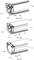
- Fig. 6 shows a perspective schematic view of a bottom end element 611a and a top end element 611b in an assembled state according to an embodiment of the invention
- Fig. 7 shows a schematic cross-sectional view of a bottom element 61a and a top element 61b of the top casing 61.
- the bottom end element 611a comprises a plurality of connectors for connecting the bottom end element 611a to the bottom element 61a.
- the connectors may be configured for providing a screw or snap connection between the bottom end element 611a and the bottom element 61a.
- the connectors of the bottom end element 611a comprise two bottom connection openings 612a, 619a for facilitating a screw connection between the bottom end element 611a and the bottom element 61a.
- the bottom connection openings 612a, 619a are thus configured to accommodate screws.
- the bottom connection openings 612a, 619a are in the assembled state aligned with bottom tracks 61a1, 61a2 provided in the bottom element 61a.
- screws (not shown) are inserted through the bottom connection openings 612a, 619a and into the bottom tracks 61a1, 61a2, thus connecting the bottom end element 611a to the bottom element 61a.
- the bottom end element 611a comprises a bottom flange receiving element 618a.
- the bottom flange receiving element 618a is configured to receive a top flange 61b2 formed by the top element 61b.
- the top flange 61b2 is hooked into the bottom flange receiving element 618a, thus connecting the bottom end element 611a with the top element 61b.
- the top end element 611b comprises at least one connector for connecting the top end element 611b to the top element 61b.
- the connector may be for providing a screw or snap connection between the bottom end element 611a and the bottom element 61a.
- the top end element 611b comprises a connector in the form of one top connection opening 612b for facilitating a screw connection between the top end element 611b and the top element 61b.
- the top connection opening 612b is configured to accommodate a screw.
- the top connection opening 612b is in the assembled state aligned with a top track 61b1 formed by the top element 61b.
- the bottom end element 611a and the top end element 611b defines an engagement through-hole 612.
- the engagement through-hole 612 extends from the reel space 61w to the bar space 61p.
- the engagement through-hole 612 allows the engagement means 675 of the winding reel 671 to extend from the reel space 61w and into the roller bar 61r arranged in the bar space 61p.
- top element 61b of the top casing 61 is seen to be provided with flange 71 forming part of the suspension device 70 for mounting the screening arrangement to the roof window 1.
- FIG. 8 showing a partially exploded perspective schematic view of a right-hand side of the top casing 61 with the roller bar 61r according to an embodiment of the invention.
- the top end element 611b is seen in an exploded state away from the rest of the top casing 61.
- the top element 611b comprises a plurality of connectors for connecting the top end element 611b to the bottom end element 611a.
- the connectors may be for providing a screw or snap connection between the top end element 611b and the bottom end element 611a.
- these connectors are formed as follows:
- One of the top connectors is formed as a top connection opening 614b for facilitating a screw between the top end element 611b and the bottom end element 611a.
- the bottom end element 611a comprises a corresponding bottom connection opening 614a.
- the top connection opening 614b is aligned with the corresponding bottom connection opening 614a and a screw may be inserted through the openings 614a, 614b, thus connecting the bottom end element 611a to the top end element 611b.
- a screw may be inserted through the end cover 613R, 613L and through the corresponding connection openings 614a, 614b of the bottom end element 611a and the top end element 611b to connect the end cover 613R, 613L to the bottom end element 611a and the top end element 611b.
- the top end element 611b comprises a top dome 613b with a central bore extending through it.
- the bottom end element 611a comprises a bottom dome 613a with a central bore extending through it.
- the top dome 613b is received within the bottom dome 613a.
- the top dome 613b is received rotatably within the bottom dome 613a, thus forming a pivot connection between the top end element 611b and the bottom end element 611a.
- the pivot connection allows the top element 611b to rotate between an open state, cf. Figs 9 and 10 , and a closed state, cf. Fig 6 .
- a screw may be inserted through the central bores of the top dome 613b and the bottom dome 613a to further connect the domes 613a, 613b together.
- a screw may be inserted through the end cover 613R, 613L and through the domes 613a, 613b of the bottom end element 611a and the top end element 611b to connect the end cover 613R, 613L to the bottom end element 611a and the top end element 611b.
- the bottom end element 611a and the top end element 611b further comprises a plurality of connection openings for connecting the end cover 613R, 613L to the bottom end element 611a and the top end element 611b.
- One or more screws may be inserted through openings in the end cover 613R, 613L and into connection openings of the bottom end element 611a and the top end element 611b to connect the end cover 613R, 613L with the bottom end element 611a and the top end element 611b.
- FIGs 9 and 10 showing different perspective schematic views of a bottom end element 611a and a top end element 611b, where the end element 611b is in an open state, according to an embodiment of the invention.
- the bottom end element 611a and the top end element 611b comprises one or more first support surfaces 615a, 616a, 615b, 616b.
- the bottom end element 611a comprises a minor support surface 615a and a major support surface 616a.
- the minor support surface 615a and the major support surface 616a each extends from a perimeter of the engagement through-hole 612 defined by the top end element 611b and the bottom end element 611a in the assembled state.
- the major support surface 616a extends from larger part of the perimeter relative to the minor support surface 615a.
- the major support surface 616a is arranged to receive a resulting force from the winding reel 671 caused by movement of the screening body 65.
- the top end element 611b comprises two minor support surfaces 615b, 616b.
- the minor support surfaces 615b, 616b of the top end element extends from a perimeter of the engagement through-hole 612.
- the support surfaces 615a, 616a, 615b, 616b are adapted for supporting the winding reel 671 and facilitating rotation of the winding reel 671 in a winding direction and an unwinding direction.
- the bottom end element further 611a comprises a cord passage 610.
- the cord passage 610 allows the cord 67 (not shown in this figure) to pass from the side rail 63 and into the reel space 61w.
- the bottom end element further comprises a winding support 617a.
- the winding support 617a is adapted for supporting the winding reel 671 and for guiding the cord 67 connected to the winding reel 671 towards the cord passage 610.
- the end cover 613R is configured to form the right-hand end cover in the assembled screening device 60 in the embodiment shown, and comprises a plurality of connectors in the form of cover connection openings 614, 615, 616, 617 for connecting the end cover 613R to the bottom end element 611a and the top end element 611b.
- the connectors 614, 615, 616, 617 may be for providing a screw or snap connection between the end cover 613 and the bottom end element 611a and the top end element 611b.
- the end cover 613 comprises four cover connection openings 614, 615, 616, 617 for facilitating a screw connection between the end cover 613 and the bottom end element 611a and the top end element 611b.
- the cover connection openings 614, 615, 616, 617 are in the assembled state aligned with bottom connection openings 612a, 613a in the bottom end element 611a and top connection openings 612b, 613b in the top end element 611b.
- the end cover 613 comprises one or more second support surfaces 613s.
- the end cover 613 comprises four second support surfaces 613s.
- the second support surfaces 613s extends perpendicularly from a side of the end cover facing the reel space 61w.
- the relative placement of the second support surfaces 613s substantially corresponds to that of the first support surfaces 615a, 616a, 615b, 616b.
- the sizes of the second support surfaces 613s substantially correspond to those of the first support surfaces 615a, 616a, 615b, 616b.
- the positioning of the second support surfaces 613s substantially corresponds to a linear displacement of the first support surfaces 615a, 616a, 615b, 616b, along a direction parallel to the longitudinal extension of the roller bar 61r.
- FIGs 13a and 13b showing different perspective schematic views of an end cover according to another embodiment of the invention. Elements having the same or analogous function as in the embodiment of Figs 11 and 12 are denoted by the same reference numerals. Only differences will be described in detail.
- the end cover 613L shown in Figs 13a and 13b is configured to form the left-hand end cover in the embodiment shown.
- the features of the end cover 613L depicted in Figs 13a and 13b substantially correspond to the features of the end cover 613R depicted in Figs 11 and 12 .
- the depicted end cover 613L further comprises a through-hole 618.
- the through-hole 618 extends through the end cover 613 and provides a passage through the end cover 613.
- the through-hole 618 is aligned with the engagement through-hole 612.
- the through-hole 618 allows drive means to be inserted through the end cover 613 and the engagement through-hole 612 into the roller bar 61r.
- FIG. 14 Details of an embodiment of a screening arrangement including drive means in the form of a motor unit 68 is shown in Fig. 14 , in which the left-hand end cover 613 shown in Figs 13a and 13b is shown together with winding reel 671 together with the motor unit 68. It is noted that details of the top casing 61 itself are not shown, including bottom and top elements etc.
- FIGs 15a to 15f showing perspective schematic views of the right-hand corner of a top casing at different stages of assembly. While the steps are shown referring to details of the top casing 61 of the embodiments of the screening arrangement 50 described in the above, such steps are also applicable to elements that have been modified within the framework of the appended claims.
- a bottom element 61a and a roller bar 61r is provided in Fig. 15a .
- the roller bar 61r is received by the bottom element 61a and supported by the bottom element 61a.
- a bottom end element 611a has been provided.
- the bottom end element 611a is connected to the bottom element 61a via a snap connection or a screw connection.
- the end element 611a comprises bottom connection openings 612a, 619a, and the end element 61a comprises bottom tracks 61a1, 61a2.
- the bottom end element 611a is connected to the bottom element 61a by inserting screws through the connection openings 612a, 619a, and into the bottom tracks 61a1, 61a2.
- a top end element 611b has been provided.
- the top end element 611b comprises a top dome 613b and the bottom end element 611a comprises a bottom dome 613a.
- the end element 611b is connected to the bottom end element 611a, by inserting the top dome 613b, of the top end element 611b into the bottom dome 613a of the bottom end element 611a.
- the domes 613a, 613b pivotally connects the top end element 611b to the bottom end element 611a.
- a winding reel 671 has been provided.
- the winding reel 671 comprises engagement means 672.
- the winding reel 671 is connected to the roller bar 61 by inserting the engagement means 672 of the winding reel 671 through an engagement hole 612 formed by the top end element 611b and the bottom end element 611a.
- a top element 61a has been provided.
- the top element 61a is connected to the bottom end element 611a and the top end element 611b.
- the top element 61a is connected to the bottom end element 611a by hooking a top flange 61b2 of the top element onto a bottom flange receiving element 618a of bottom end element 611b.
- the top element 61a is connected to the top end element 611a by inserting a screw through a top connection opening 612b in the top end element 611b and into a top track 61b1 of the top element 61b.
- an end cover 613R has been provided.
- the end cover 613R is connected to the bottom end element 611a and the top end element 611b.
- the end cover 613R is connected by aligning one or more cover openings 614, 615, 616, 617 with bottom connection openings 612a, 613a in the bottom end element 611a and top connection openings 612b, 613b in the top end element 611b.
- connection of the second longitudinal end 61r2 of the roller bar 61r and the opposite winding reel 671 to the top casing 61 is carried out in substantially the same manner.
- such end cover may take the form of left-hand end cover 613L to which a motor unit 68 is connected.
- FIG. 17 shows the upper left-hand corner of the screening device 60 of an embodiment of the screening arrangement 50 according to the invention in a mounted condition. It is noted that a subjacent roof window or skylight is not shown, just as the corner cover element (82) has been removed, and the solar panel 61s is shown in an exploded view.
- the solar panel 61s is formed by a solar panel frame 61s1 which is positioned on top of a solar panel element 61s2 to overlap the solar panel element 61s2 in the mounted condition.
- a solar panel arm 61s3 is provided to position the solar panel 61s correctly relative to the top casing 61.
- the solar panel arm 61s3 has the additional function of acting as a guide for a solar panel cable 61s4 extending from the solar panel element 61s2 (or non-shown circuitry connected thereto) and the drive means of the screening device 60.
- the solar panel frame 61s1 is kept in abutment with the top casing 61 by means of an adhesive pad 61s5. Further elements shown include solar panel labels 61s6, and the flap 613f of the end cover 613L.
- the invention is not limited to this order.
- the top end element 611b is connected to the bottom end element 611a, and then the assembled bottom end element 611a and the top end element 611b is connected to the top element 61b and the bottom element 61a.
- the winding reel 671 is connected to the roller bar 61r after the top element 61b has been connected to the bottom end element 611a and the top end element 611b.
Abstract
Description
- A screening arrangement for a roof window, and roof window comprising such a screening arrangement.
- The invention relates to a screening arrangement according to the preamble of
claim 1. The invention furthermore relates to a roof window comprising such a screening arrangement. - Screening arrangements also must fulfil different requirements depending on whether they are installed in a façade window, i.e. in a substantially vertical position, or in an inclined or even horizontal surface such as a roof.
- Not only are screening arrangements for roof windows configured to take into account the effects of gravity due to the resulting force being out of the general plane of the roof window, but the mounted position itself, on a roof, puts large demands to the components of the external screening arrangement.
- In known prior art screening arrangements, the manufacturing of the screening arrangement may be quite a complicated process with small margins for errors. For example, small clearances may be present during assembly, e.g. when connection or otherwise introducing components into each other. These small clearances may lead to nicks and bump being created by unwanted contact in-between components. Alternatively, an additional amount of time or steps is needed to avoid the small clearances being problematic.
- A prior art screening arrangement of the kind mentioned in the preamble of
claim 1 is shown and described inEP 2 236 731 A2 - With this background, it is therefore an object of the invention to provide a screening arrangement, which eases manufacturing of the screening arrangement.
- In a first aspect, this and further objects are achieved by a screening arrangement of the kind mentioned in the introduction, which is furthermore characterised in that the screening arrangement comprises a winding device comprising at least one winding reel in connection with or connectable to the roller bar at the first longitudinal end of the roller bar, that the top casing comprises a bottom end element and a top end element adjacent to the first longitudinal end of the roller bar and further delimiting the bar space, the bottom end element and the top end element delimiting a reel space accommodating and limiting movement of the at least one winding reel, and that the bottom element of the top casing is configured to receive and support the roller bar during assembly of the screening arrangement and the top element is configured to be connected to the bottom element subsequent to the bottom element receiving the roller bar.
- Consequently, by firstly supporting the roller bar on the bottom element and then subsequently connecting the top element the ease of assembling the top casing is improved. The roller bar does not need to be introduced along an opening in the top casing, instead the top casing is formed around the roller bar. Thus, the handling of the roller bar is eased during assembly of the screening arrangement. Since the winding device comprising a winding reel at one or both ends of the roller bar is present, the formation of a space limiting movement of the winding reel, the assembly of the screening device is further eased as the risk of unwanted movement of winding reel(s) during assembly is minimized.
- In an embodiment the at least one winding reel comprises engagement means adapted for connecting the at least one winding reel to the roller bar, wherein the bottom end element and the top end element are configured to form an engagement through-hole extending from the reel space to the bar space, and wherein the engagement means extends through the engagement through-hole and into the roller bar. Consequently, the top casing is formed in a simple and efficient manner where movement of the winding reel and the roller bar is limited, while still allowing the roller bar and the winding reel to be connected to each other.
- In an embodiment the engagement means are formed as one or more snap-legs engaged in a snap-connection with one or more corresponding connectors in the roller bar. Consequently, the winding reel may be connected to the roller bar by simply inserting the engagement means into the roller bar. The connection between the roller bar and the winding reel does not need tools for being formed, thus simplifying assembly, and obviating the need for additional space to accommodate a tool.
- In an embodiment, the top casing comprises an end cover further delimiting the reel space. In addition to providing closure of the interior of the top casing such that dust and other contaminants are hindered from negatively affecting the winding reel, the end cover may also provide support for the winding reel.
- In an embodiment a through-hole is formed in the end cover aligned with the engagement through-hole formed by the bottom end element and the top end element to allow drive means to be inserted through the through-hole and the engagement through-hole into the roller bar. Thus, it is for instance possible to include a motor unit to be connected to one end cover, whereas the other end cover is of a more simple structure.
- In a further development of the embodiment comprising one or two end covers, the end cover comprises one or more second support surfaces supporting the winding reel and facilitating rotation of the winding reel in the winding direction and the unwinding direction. This ensures suitable rotational support for the winding reel.
- In an embodiment the bottom end element and/or the top end element comprises one or more first support surfaces supporting the winding reel and facilitating rotation of the winding reel in the winding direction and the unwinding direction. Consequently, movement of the winding reel is facilitated, which in return facilitates movement of a screening body.
- In principle, the top and bottom elements may be connected to each other in any suitable way, as long as they allow for initial reception of the roller bar by the bottom element during assembly. In an embodiment, the bottom end element is connected to the bottom element and the top end element, wherein the top end element is connected to the top element, and wherein the bottom element is connected to the top element via the bottom end element and the top end element. This facilitates the assembly of the screening arrangement even further.
- In further embodiments, the bottom end element and the top end element each comprises a plurality of connectors for connecting the bottom end element to the bottom element and for connecting the top end element to the top element. Suitable connectors include releasable engagement means including screws and openings, but could also include snap or frictional engagements means.
- In one embodiment, the bottom end element is connected to the top end element by a set of connectors, preferably including a first, pivotal connection, more preferably also in a also in second, releasable connection. A pivotal connection provides for a particularly simple mounting, since the elements are easily fit into the assembled position.
- In a further embodiment, the winding device forms part of a cord system comprising a set of cords, the at least one winding reel, and optionally return elements and/or tightening means for the cords. The cord or cords of the cord system may either be wound on the winding reel before assembly of the winding reel with the respective end of the roller bar, or later, i.e. once the winding reel is located in the reel space. Typically, two winding reels are present, one at each longitudinal end of the roller bar.
- While the screening arrangement could in principle be used to screen an arbitrary opening, it is preferred that the screening arrangement is adapted for a skylight or roof window. In such structures, the possible assistance from gravity forces during unwinding of the screening body is negligeable.
- In a second aspect of the invention the objects set forth are achieved by a method for assembling a top casing with a roller bar for a screening arrangement, comprising the steps of:
- providing a bottom element, a top element and a roller bar,
- providing a bottom end element and a top end element,
- supporting the roller bar on the bottom element,
- fixedly connecting the bottom end element to the bottom element,
- pivotally connecting the bottom end element to the top end element, wherein the top end element is pivotal between an open state and a closed state,
- fixedly connecting, when the top end element is in the closed state, the top end element to the top element and thereby
- enclosing the roller bar by connecting the top element to the bottom element, wherein a bar space is formed in-between the bottom element and the top element, and wherein the bar space accommodates and limits movement of the roller bar.
- Other presently preferred embodiments and further advantages will be apparent from the subsequent detailed description and drawings.
- A feature described in relation to one of the aspect may also be incorporated in the other aspect, and the advantage of the feature is applicable to all aspects in which it is incorporated.
- For exemplifying purposes, the invention will be described in closer detail in the following with reference to embodiments thereof illustrated in the attached drawings, wherein:
-
Fig. 1 is a perspective view of a screening arrangement in a first embodiment of the invention; -
Figs 2 and 3 are perspective views of screening arrangements in other embodiments of the invention; -
Fig. 4 is a perspective, partially sectioned view of a screening arrangement in the first embodiment of the invention installed in a roof window mounted in a roof structure; -
Fig. 5 is an exploded, perspective schematic view of a right-hand side of a top casing with a roller bar according to an embodiment of the invention. -
Fig. 6 is a perspective schematic view of a bottom end element and a top end element in an assembled state according to an embodiment of the invention. -
Fig. 7 is a schematic cross-sectional view of a bottom element and a top element according to an embodiment of the invention. -
Fig. 8 is a partially exploded perspective schematic view of a right-hand side of a top casing with a roller bar according to an embodiment of the invention. -
Figs 9 and 10 are perspective schematic views of a bottom end element and a top end element, where the end element is in an open state, according to an embodiment of the invention. -
Figs 11 and 12 are different perspective schematic views of an end cover according to an embodiment of the invention. -
Figs 13a and 13b are different perspective schematic views of an end cover according to another embodiment of the invention. -
Fig. 14 is an exploded perspective view of details of an embodiment of a screening arrangement including drive means comprising a motor unit. -
Figs 15a to 15e are perspective schematic views of the right-hand corner of a top casing at different stages of assembly. -
Fig. 16 is a perspective view of a cord system forming part of an embodiment of the screening arrangement according to the invention. -
Fig. 17 is an exploded partial perspective view of details of a screening arrangement in an embodiment of the invention. - In the following detailed description, preferred embodiments of the present invention will be described. However, it is to be understood that features of the different embodiments are exchangeable between the embodiments and may be combined in different ways, unless anything else is specifically indicated. It may also be noted that, for the sake of clarity, the dimensions of certain components illustrated in the drawings may differ from the corresponding dimensions in real-life implementations.
- It is noted that terms such as "up", "down", "left-hand", "right-hand", "exterior", "interior", "outer", "inner" are relative and refers to the viewpoint in question.
- Referring initially to
Figs 1 and4 , a first embodiment of ascreening arrangement 50 is shown. Thescreening arrangement 50 is configured to be installed in aroof window 1 installed in an inclined orflat roof 2 of a building to cover anopening 1a of theroof window 1 in a mounted condition of thescreening arrangement 50. Theopening 1a of theroof window 1 is positioned opposite anopening 2a provided in theroof 2. By the term roof window is in principle meant any window suitable for being installed in a roof. By flat roof is generally meant roofs having an inclination of 0 to 5° and by inclined roofs inclinations larger than 5°, for instance up to 45° or 65°. - The
screening arrangement 50 comprises ascreening device 60 including atop casing 61 and ascreening body 65 having two side edges, a first end portion and a second end portion. Thescreening body 65 is movable in a longitudinal direction between a non-screening position, in which thescreening body 65 is substantially accommodated in thetop casing 61, and a number of screening positions in which thescreening body 65 is deployed from thetop casing 61 and covers the opening partially or entirely. Thescreening body 65 may take the form of a flexible cloth which is rolled up when accommodated in the top casing and is substantially plane when rolled out in a deployed screening position. The screening body may be opaque to form a darkening or blackout blind or admit a certain amount of incoming light in the screening position, for instance as in an awning blind. Regardless of the configuration, thescreening body 65 defines a screening plane when deployed to a screening position. The first end portion of thescreening body 65 is connected to aroller bar 61r (cf. for instanceFig. 5 )accommodated in thetop casing 61 and its other end portion is in the embodiment shown connected to abottom bar 66. While reference to a blind which is rolled-up in the non-screening position is made in the above and throughout the embodiments of the invention, the principles of the invention are applicable also to other types of screening devices such as for instance a pleated blind, being folded up when accommodated, or a Venetian blind or other screens including a number of lamellas forming the screening body and which are collected on a collection device equivalent to theroller bar 61r, when accommodated in thetop casing 61. - The
screening device 60 furthermore comprises twoside rails top casing 61 in the mounted condition of thescreening arrangement 50 and which guide the side edges of thescreening body 65 during its movement to and from its deployed positions. Together, thetop casing 61 and the twoside rails screening device 60. In the first embodiment shown inFigs 1 and4 , thescreening device 60 comprises abottom profile 62 which is shown in a position connected to the side rails 63, 64. The connection between the twoside rails top casing 61 at one end and thebottom profile 62 at the other advantageously takes place before installing thescreening device 60 in theroof window 1, as thescreening device 60 may for instance be delivered in a supply condition in which the twoside rails top casing 61 and thebottom profile 62 are packaged in parallel with each other. - In order to move the
screening body 65 from the non-screening position to a screening position and back, thescreening arrangement 50 is in the first embodiment provided with asolar panel 61s placed in thetop casing 61 which could be used to power thescreening arrangement 50, possibly connected to a battery inside thetop casing 61; however, power may also be provided from a main housing supply, as indicated in the alternative embodiments ofFigs 2 and 3 , where no solar panel is present. Wiring, motor control and power means for the motor are not shown in either of the embodiments. - The
screening device 60 thus forms a rectangular shape having a closed configuration in the first embodiment ofFigs 1 and4 . In the alternative embodiments ofFigs 2 and 3 , it is noted that no bottom profile is present. While the shape of thescreening device 60 in each of these alternative embodiments is rectangular, the configuration is open in the form of a U. When seen in the general plane of thescreening device 60 as defined by its screening body, an outer perimeter of thescreening device 60 is formed by peripherally outermost surfaces of thetop casing 61, the twoside rails bottom profile 62, or, if no bottom profile is present, by a line extending between the free ends of the side rails 63, 64. - The
screening arrangement 50 furthermore comprises asuspension device 70 connected to or connectable to thescreening device 60 as will be described in further detail below. Thesuspension device 70 comprises means for connecting thescreening device 60 to theroof window 1 in that thesuspension device 70 of the screening arrangement comprises a plurality of flanges associated to a respective one of thetop casing 61 and the twoside rails screening device 60, and, if present, to thebottom profile 62. InFig. 4 ,flanges - Each
flange suspension device 70 intended to cooperate with a corresponding component of theroof window 1 in the mounted condition of thescreening arrangement 50. InFig. 4 , three such lines of contact LC1, LC2 and LC4 are shown. It is understood that a corresponding line of contact is present at the flange 73 connected to theother side rail 63. - It is noted that each
flange suspension device 70 is configured to protrude from the respective one of thetop casing 61 and the twoside rails bottom profile 62 such that the lines of contact LC1, LC2, LC4 are positioned to the outer side of an outer perimeter of thescreening device 60 in the mounted condition of the screening arrangement, i.e. outside the outer perimeter or periphery of the components of thescreening device 60 as described in the above. - The side rails 63, 64 are formed as longitudinally extending profiles which are cut transversely to the length direction to form blunt opposing ends. Due to the configuration of the
top casing 61 and the width of the side rails 63, 64 an opening is formed at the corners in-between thetop casing 61 and the twoside rails - In order to ensure that dust and other contaminants enter the top casing and/or the side rails, the
screening arrangement 50 furthermore comprises acorner cover assembly 80 to interact with thescreening device 60 and thesuspension device 70 in the mounted condition of the screening arrangement. Thecorner cover assembly 80 also provides light-proofing in that it hinders light from passing the screening arrangement. This is most important in connection with blackout screening devices, as it blocks the openings formed in the screening arrangement, thus hindering the passage of light through the screening arrangement and further into the interior of the room of the building. - In the first embodiment, the
corner cover assembly 80 comprises a first and a secondcorner cover element top casing 61 and the twoside rails screening device 60 and with arespective flange suspension device 70 such that the intersection between adjacent lines of contact LC1, LC2, LC4, or extensions of the lines of contact, is located below a respective one of the first andsecond cover element corner cover element bottom profile 62 of thescreening device 60 and with arespective flange 73, 74 of thesuspension device 70. This configuration also applies to the alternative embodiment ofFig. 2 , whereas in the embodiment ofFig. 3 , no third or fourth cover elements are present. - Turning now in particular to
Fig. 4 , theroof window 1 comprises awindow portion 4 with awindow sash 6 and an insulating glazing unit 5. Thesash 6 comprises opposing first andsecond sash members fourth sash member 14 is shown inFig. 4 , encasing the insulating glazing unit 5. Thesash 6 is connected to aframe 7 comprising fourframe members 10. The shape of thesash 6 andframe 7 is thus rectangular, for instance square. Thesash 6 may be openable relative to theframe 7 or fixed. - The
roof window 1 furthermore comprises aweather shield 3 positioned above the insulating glazing unit 5 and comprising aweather shield pane 8 and askirt 9. Theweather shield 3 has been moved out of engagement with thewindow portion 4 inFig. 4 for reasons of clarity. Theweather shield pane 8 is substantially plane; however, it is conceivable to install thescreening arrangement 50 also in roof windows having a curved pane. Theweather shield 3 may be openable relative to thewindow portion 4 or fixed. - The
screening arrangement 50 is arranged in a spacing between an exterior surface of the insulating glazing unit 5 of thewindow portion 4 and an interior surface of theweather shield pane 8 of theweather shield 3 such that thescreening device 60 is located below an exterior side of thefirst sash member 11 in the mounted condition of thescreening arrangement 50. - Referring to
Fig. 5 showing an exploded, perspective schematic view of a right-hand side of thetop casing 61 with theroller bar 61r according to an embodiment of thescreening arrangement 50 of the invention. - The
top casing 61 comprises abottom element 61a. Thebottom element 61a extends longitudinally to form part of abar space 61p for receiving theroller bar 61r. Atop element 61b extends longitudinally in parallel with thebottom element 61b. Thetop element 61b in the assembled condition of thescreening arrangement 50 delimits thebar space 61p together with thebottom element 61a. - The screening arrangement comprises a winding device comprising a winding
reel 671. The windingreel 671 comprises a windingtrack 675 for accommodating acord 67c, seeFig. 16 . The windingreel 671 and thecord 67c here form part of acord system 67 for moving thescreening body 65 along the side rails 63, 64. In the embodiment shown inFig. 16 , twocords 67c are provided to extend from thebottom bar 66 to the windingreel 671 at the respective longitudinal end 61r1 and 61r2 of theroller bar 61r, via a return element such as a pulley or the like (not indicated) provided at or near the ends of the side rails opposite thetop casing 61, possibly provided in thebottom profile 62, if present. Tightening means (not shown) may also be provided to keep the cord orcords 67c of the cord system 57 tightened. The windingtrack 675 is delimited by a first windingflange 673 and a second windingflange 674. The first windingflange 673 and the second windingflange 674 extend from a perimeter of the windingtrack 675. Extending in parallel withbottom element 61a and thetop element 61b is engagement means 672 for connecting the windingreel 675 to theroller bar 61r. The engagement means are in the embodiment shown formed as one or more snap-legs, here three snap-legs 672. The snap-legs 672 are configured to engage one or more roller bar connectors 61r3 arranged in theroller bar 61r in a snap connection. - The
roller bar 61r extends longitudinally between a first longitudinal end 61r1 and a second longitudinal end 61r2. In the assembled state, theroller bar 61r extends longitudinally in parallel with thebottom element 61a and thetop element 61b. - The
top casing 61 further comprises abottom end element 611a and atop end element 611b. In an assembled state of thetop casing 61 thebottom end element 611a and thetop end element 611b are arranged adjacent to the first longitudinal end 61r1 of theroller bar 61r and further delimit thebar space 61p together with thebottom element 61a and thetop element 61b. Thebottom end element 611a and thetop end element 611b delimit areel space 61w. In the assembled state at least, part of the windingreel 671 is arranged within the reel space, preferably thetrack 675, the first windingflange 673 and the second windingflange 674. Thereel space 61w is intended for accommodating and limiting movement of the at least one windingreel 671. - In the embodiment shown, the
top casing 61 is closed off by a set of end covers. Oneend cover 613R is shown inFig. 5 and further delimits thereel space 61w. Anopposite end cover 613L is present at the opposite longitudinal end of the top casing. Although not shown in detail, a counterpart winding reel is in engagement with a bottom end element and a top end element at the opposite end. Consequently, the windingreel 671 received in thereel space 61w is kept from moving unnecessarily in the longitudinal direction by the end covers 613R and 613L, and the respectivebottom end element 611a and thetop end element 611b. In the rotational direction, the windingreel 671 is rotationally supported by the respective end cover 631R, 631L and thebottom end element 611a andtop end element 611b as will be described in further detail below. - Referring to
Fig. 6 and7 , whereFig. 6 shows a perspective schematic view of abottom end element 611a and atop end element 611b in an assembled state according to an embodiment of the invention, andFig. 7 shows a schematic cross-sectional view of abottom element 61a and atop element 61b of thetop casing 61. - The
bottom end element 611a comprises a plurality of connectors for connecting thebottom end element 611a to thebottom element 61a. The connectors may be configured for providing a screw or snap connection between thebottom end element 611a and thebottom element 61a. - In the shown embodiment, the connectors of the
bottom end element 611a comprise twobottom connection openings bottom end element 611a and thebottom element 61a. In the shown embodiment, thebottom connection openings bottom connection openings bottom element 61a. When assembling thetop casing 61 screws (not shown) are inserted through thebottom connection openings bottom end element 611a to thebottom element 61a. - Furthermore, the
bottom end element 611a comprises a bottomflange receiving element 618a. The bottomflange receiving element 618a is configured to receive a top flange 61b2 formed by thetop element 61b. When assembling thetop casing 61 the top flange 61b2 is hooked into the bottomflange receiving element 618a, thus connecting thebottom end element 611a with thetop element 61b. - Correspondingly, the
top end element 611b comprises at least one connector for connecting thetop end element 611b to thetop element 61b. The connector may be for providing a screw or snap connection between thebottom end element 611a and thebottom element 61a. - In the shown embodiment, the
top end element 611b comprises a connector in the form of one top connection opening 612b for facilitating a screw connection between thetop end element 611b and thetop element 61b. In the shown embodiment, the top connection opening 612b is configured to accommodate a screw. The top connection opening 612b is in the assembled state aligned with a top track 61b1 formed by thetop element 61b. When assembling thetop casing 61 a screw is inserted through the top connection opening 612b and into the top track 61b1, thus connecting thetop end element 611b to thetop element 61b. - In the assembled state the
bottom end element 611a and thetop end element 611b defines an engagement through-hole 612. The engagement through-hole 612 extends from thereel space 61w to thebar space 61p. The engagement through-hole 612 allows the engagement means 675 of the windingreel 671 to extend from thereel space 61w and into theroller bar 61r arranged in thebar space 61p. - Furthermore, the
top element 61b of thetop casing 61 is seen to be provided withflange 71 forming part of thesuspension device 70 for mounting the screening arrangement to theroof window 1. - Referring to
Fig. 8 showing a partially exploded perspective schematic view of a right-hand side of thetop casing 61 with theroller bar 61r according to an embodiment of the invention. - The
top end element 611b is seen in an exploded state away from the rest of thetop casing 61. Thetop element 611b comprises a plurality of connectors for connecting thetop end element 611b to thebottom end element 611a. The connectors may be for providing a screw or snap connection between thetop end element 611b and thebottom end element 611a. - In the shown embodiment, these connectors are formed as follows: One of the top connectors is formed as a top connection opening 614b for facilitating a screw between the
top end element 611b and thebottom end element 611a. Thebottom end element 611a comprises a correspondingbottom connection opening 614a. When connecting thetop end element 611b to thebottom end element 611a, the top connection opening 614b is aligned with the correspondingbottom connection opening 614a and a screw may be inserted through theopenings bottom end element 611a to thetop end element 611b. - In some embodiments a screw may be inserted through the
end cover corresponding connection openings bottom end element 611a and thetop end element 611b to connect theend cover bottom end element 611a and thetop end element 611b. - In the embodiment shown, the
top end element 611b comprises atop dome 613b with a central bore extending through it. Thebottom end element 611a comprises abottom dome 613a with a central bore extending through it. During assembly thetop dome 613b is received within thebottom dome 613a. Thetop dome 613b is received rotatably within thebottom dome 613a, thus forming a pivot connection between thetop end element 611b and thebottom end element 611a. The pivot connection allows thetop element 611b to rotate between an open state, cf.Figs 9 and 10 , and a closed state, cf.Fig 6 . Furthermore, a screw may be inserted through the central bores of thetop dome 613b and thebottom dome 613a to further connect thedomes - In some embodiments a screw may be inserted through the
end cover domes bottom end element 611a and thetop end element 611b to connect theend cover bottom end element 611a and thetop end element 611b. - As will be described in more detail in the following, the
bottom end element 611a and thetop end element 611b further comprises a plurality of connection openings for connecting theend cover bottom end element 611a and thetop end element 611b. One or more screws may be inserted through openings in theend cover bottom end element 611a and thetop end element 611b to connect theend cover bottom end element 611a and thetop end element 611b. - Referring to
Figs 9 and 10 showing different perspective schematic views of abottom end element 611a and atop end element 611b, where theend element 611b is in an open state, according to an embodiment of the invention. - The
bottom end element 611a and thetop end element 611b comprises one or morefirst support surfaces bottom end element 611a comprises aminor support surface 615a and amajor support surface 616a. Theminor support surface 615a and themajor support surface 616a each extends from a perimeter of the engagement through-hole 612 defined by thetop end element 611b and thebottom end element 611a in the assembled state. Themajor support surface 616a extends from larger part of the perimeter relative to theminor support surface 615a. Preferably, themajor support surface 616a is arranged to receive a resulting force from the windingreel 671 caused by movement of thescreening body 65. - In the shown embodiment, the
top end element 611b comprises twominor support surfaces minor support surfaces hole 612. - The support surfaces 615a, 616a, 615b, 616b are adapted for supporting the winding
reel 671 and facilitating rotation of the windingreel 671 in a winding direction and an unwinding direction. - The bottom end element further 611a comprises a
cord passage 610. Thecord passage 610 allows the cord 67 (not shown in this figure) to pass from theside rail 63 and into thereel space 61w. - The bottom end element further comprises a winding
support 617a. The windingsupport 617a is adapted for supporting the windingreel 671 and for guiding thecord 67 connected to the windingreel 671 towards thecord passage 610. - Referring to
Figs 11 and 12 showing different perspective schematic views of anend cover 613R according to an embodiment of the invention. Theend cover 613R is configured to form the right-hand end cover in the assembledscreening device 60 in the embodiment shown, and comprises a plurality of connectors in the form ofcover connection openings end cover 613R to thebottom end element 611a and thetop end element 611b. Theconnectors bottom end element 611a and thetop end element 611b. In the shown embodiment, the end cover 613 comprises fourcover connection openings bottom end element 611a and thetop end element 611b. Thecover connection openings bottom connection openings bottom end element 611a andtop connection openings top end element 611b. When assembling thetop casing 61 screws are inserted through theend cover openings bottom connection openings top connection openings bottom end element 611a and theend element 611b. - Furthermore, the end cover 613 comprises one or more second support surfaces 613s. In the shown embodiment, the end cover 613 comprises four second support surfaces 613s. The second support surfaces 613s extends perpendicularly from a side of the end cover facing the
reel space 61w. The relative placement of the second support surfaces 613s substantially corresponds to that of thefirst support surfaces first support surfaces first support surfaces roller bar 61r. - Referring to
Figs 13a and 13b showing different perspective schematic views of an end cover according to another embodiment of the invention. Elements having the same or analogous function as in the embodiment ofFigs 11 and 12 are denoted by the same reference numerals. Only differences will be described in detail. Theend cover 613L shown inFigs 13a and 13b is configured to form the left-hand end cover in the embodiment shown. - The features of the
end cover 613L depicted inFigs 13a and 13b substantially correspond to the features of theend cover 613R depicted inFigs 11 and 12 . However, the depictedend cover 613L further comprises a through-hole 618. The through-hole 618 extends through the end cover 613 and provides a passage through the end cover 613. The through-hole 618 is aligned with the engagement through-hole 612. The through-hole 618 allows drive means to be inserted through the end cover 613 and the engagement through-hole 612 into theroller bar 61r. - Details of an embodiment of a screening arrangement including drive means in the form of a
motor unit 68 is shown inFig. 14 , in which the left-hand end cover 613 shown inFigs 13a and 13b is shown together with windingreel 671 together with themotor unit 68. It is noted that details of thetop casing 61 itself are not shown, including bottom and top elements etc. Once thescreening arrangement 50 has been mounted on theroof window 1, it is possible to provide pairing of the motor control means of themotor unit 68 with for instance a remote control unit (not shown). Once this has been carried out, access to the interior of thetop casing 61 is closed off by aflap 613f (shown inFig. 17 ). - Referring to
Figs 15a to 15f showing perspective schematic views of the right-hand corner of a top casing at different stages of assembly. While the steps are shown referring to details of thetop casing 61 of the embodiments of thescreening arrangement 50 described in the above, such steps are also applicable to elements that have been modified within the framework of the appended claims. - In
Fig. 15a abottom element 61a and aroller bar 61r is provided. Theroller bar 61r is received by thebottom element 61a and supported by thebottom element 61a. - In
Fig. 15b abottom end element 611a has been provided. Thebottom end element 611a is connected to thebottom element 61a via a snap connection or a screw connection. Theend element 611a comprisesbottom connection openings end element 61a comprises bottom tracks 61a1, 61a2. Thebottom end element 611a is connected to thebottom element 61a by inserting screws through theconnection openings - In
Fig. 15c atop end element 611b has been provided. Thetop end element 611b comprises atop dome 613b and thebottom end element 611a comprises abottom dome 613a. Theend element 611b is connected to thebottom end element 611a, by inserting thetop dome 613b, of thetop end element 611b into thebottom dome 613a of thebottom end element 611a. Thedomes top end element 611b to thebottom end element 611a. - In
Fig. 15d a windingreel 671 has been provided. The windingreel 671 comprises engagement means 672. The windingreel 671 is connected to theroller bar 61 by inserting the engagement means 672 of the windingreel 671 through anengagement hole 612 formed by thetop end element 611b and thebottom end element 611a. - In
Fig. 15e atop element 61a has been provided. Thetop element 61a is connected to thebottom end element 611a and thetop end element 611b. Thetop element 61a is connected to thebottom end element 611a by hooking a top flange 61b2 of the top element onto a bottomflange receiving element 618a ofbottom end element 611b. Thetop element 61a is connected to thetop end element 611a by inserting a screw through a top connection opening 612b in thetop end element 611b and into a top track 61b1 of thetop element 61b. - In
Fig. 15f anend cover 613R has been provided. Theend cover 613R is connected to thebottom end element 611a and thetop end element 611b. Theend cover 613R is connected by aligning one ormore cover openings bottom connection openings bottom end element 611a andtop connection openings top end element 611b. After aligning of theend cover 613R, screws are inserted through theend cover openings bottom connection openings top connection openings end cover 613R to thebottom end element 611a and theend element 611b. - Connection of the second longitudinal end 61r2 of the
roller bar 61r and the opposite windingreel 671 to thetop casing 61 is carried out in substantially the same manner. In case an end cover is provided at that end, such end cover may take the form of left-hand end cover 613L to which amotor unit 68 is connected. - Finally,
Fig. 17 shows the upper left-hand corner of thescreening device 60 of an embodiment of thescreening arrangement 50 according to the invention in a mounted condition. It is noted that a subjacent roof window or skylight is not shown, just as the corner cover element (82) has been removed, and thesolar panel 61s is shown in an exploded view. Thesolar panel 61s is formed by a solar panel frame 61s1 which is positioned on top of a solar panel element 61s2 to overlap the solar panel element 61s2 in the mounted condition. A solar panel arm 61s3 is provided to position thesolar panel 61s correctly relative to thetop casing 61. The solar panel arm 61s3 has the additional function of acting as a guide for a solar panel cable 61s4 extending from the solar panel element 61s2 (or non-shown circuitry connected thereto) and the drive means of thescreening device 60. At the end opposite the solar panel arm 61s3, the solar panel frame 61s1 is kept in abutment with thetop casing 61 by means of an adhesive pad 61s5. Further elements shown include solar panel labels 61s6, and theflap 613f of theend cover 613L. - Specific embodiments of the invention have now been described. However, several alternatives are possible, as would be apparent for someone skilled in the art.
- Although, a specific assembly order has been disclosed in relation
Figs 15a to 15f the invention is not limited to this order. For example, in some embodiments thetop end element 611b is connected to thebottom end element 611a, and then the assembledbottom end element 611a and thetop end element 611b is connected to thetop element 61b and thebottom element 61a. In another embodiment the windingreel 671 is connected to theroller bar 61r after thetop element 61b has been connected to thebottom end element 611a and thetop end element 611b. - Such and other obvious modifications must be considered to be within the scope of the present invention, as it is defined by the appended claims.
-
- 1
- roof window
- 1a
- window opening
- 2
- roof
- 2a
- roof opening
- 3
- weather shield
- 4
- window portion
- 5
- insulating glazing unit, IGU
- 6
- sash
- 7
- frame
- 8
- weather shield pane
- 9
- weather shield skirt
- 10
- frame member
- 11
- first sash member
- 12
- second sash member
- 14
- fourth sash member
- 50
- screening arrangement
- 60
- screening device
- 61
- top casing
- 61a
- bottom element
- 61a1
- bottom track
- 61a2
- bottom track
- 611a
- bottom end element
- 612a
- bottom connection opening
- 613a
- bottom dome
- 614a
- bottom connection opening
- 615a
- first bottom support surface
- 616a
- second bottom support surface
- 617a
- winding support
- 618a
- bottom flange receiving elemnt
- 619a
- bottom connection opening
- 61b
- top element
- 61b1
- top track
- 61b2
- top flange
- 61p
- bar space
- 61r
- roller bar
- 61r1
- first longitudinal end
- 61r2
- second longitudinal end
- 61r3
- roller bar connector
- 61s
- solar panel
- 61s1
- solar panel frame
- 61s2
- solar panel element
- 61s3
- solar panel arm
- 61s4
- solar panel cable
- 61s5
- solar panel adhesive pad
- 61s6
- solar panel labels
- 61w
- reel space
- 611b
- top end element
- 612b
- top connection opening
- 613b
- top dome
- 614b
- top connection opening
- 615b
- first top support surface
- 616b
- second top support surface
- 610
- cord passage
- 612
- engagement through-hole
- 613R
- end cover
- 613L
- end cover
- 613f
- flap
- 613s
- cover support surface
- 614
- cover connection opening
- 615
- cover connection opening
- 616
- cover connection opening
- 617
- cover connection opening
- 618
- through-hole
- 62
- bottom profile
- 63
- side rail
- 64
- side rail
- 65
- screening body
- 66
- bottom bar
- 67
- cord system
- 67c
- cord
- 671
- winding reel
- 672
- engagement means/snap-legs
- 673
- first winding flange
- 674
- second winding flange
- 675
- winding track
- 68
- drive means/motor unit
- 70
- suspension device
- 71
- top flange
- 72
- bottom flange
- 74
- side flange
- 80
- corner cover assembly
- 81
- corner cover element (upper right-hand)
- 82
- corner cover element (upper left-hand)
- 83
- corner cover element (lower right-hand)
- 84
- corner cover element (lower left-hand)
- LC1
- line of contact
- LC2
- line of contact
- LC4
- line of contact
Claims (15)
- A screening arrangement (50) for a roof window (1) to be installed in an inclined or flat roof (2) of a building to cover an opening (1a) of the window (1) in a mounted condition of the screening arrangement (50), where the screening arrangement (50) comprises:a screening device (60) including a top casing (61), a screening body (65) having two side edges, a first end portion and a second end portion, said screening body (65) being movable in a longitudinal direction between a non-screening position, in which the screening body (65) is substantially accommodated in the top casing (61), and a number of screening positions in which the screening body (65) is deployed from the top casing (61) and covers the opening partially or entirely, two side rails (63, 64) configured to extend substantially perpendicularly to the top casing (61) in a mounted condition of the screening arrangement (50), the top casing (61) and the two side rails (63, 64) defining an outer perimeter of the screening device (60), and a roller bar (61r) accommodated in the top casing (61) and connected to drive means, the drive means being configured to rotate the roller bar (61r) in a winding direction and an unwinding direction, the first end portion of the screening body (65) being connected to the roller bar (61r) such that the screening body (65) is wound on the roller bar (61r) in the non-screening position, and wherein the roller bar (61r) extends longitudinally between a first longitudinal end (61r1) and a second longitudinal end (61r2), the top casing (61) comprising a bottom element (61a) and a top element (61b) delimiting a bar space (61p) accommodating and limiting movement of the roller bar (61r),characterised in thatthe screening arrangement (50) comprises a winding device comprising at least one winding reel (671) in connection with or connectable to the roller bar (61r) at the first longitudinal end (61r1) of the roller bar (61r), that the top casing (61) comprises a bottom end element (611a) and a top end element (611b) adjacent to the first longitudinal end (61r1) of the roller bar (61r) and further delimiting the bar space (61p), the bottom end element (611a) and the top end element (611b) delimiting a reel space (61w) accommodating and limiting movement of the at least one winding reel (671), and that the bottom element (61a) of the top casing (61) is configured to receive and support the roller bar (61r) during assembly of the screening arrangement (50) and the top element (61b) is configured to be connected to the bottom element (61a) subsequent to the bottom element (61a) receiving the roller bar (61r).
- A screening arrangement (50) according to claim 1, wherein the at least one winding reel (671) comprises engagement means (672) adapted for connecting the at least one winding reel to the roller bar (61r), wherein the bottom end element (611a) and the top end element (611b) are configured to form an engagement through-hole (612) extending from the reel space (61w) to the bar space (61p), and wherein the engagement means (672) extends through the engagement through-hole (612) and into the roller bar (61r).
- A screening arrangement (50) according to claim 2, wherein the engagement means are formed as one or more snap-legs (672) engaged in a snap-connection with one or more corresponding connectors (61r3) in the roller bar (61r).
- A screening arrangement (50) according to any of the preceding claims, wherein the top casing (61) comprises an end cover (613) further delimiting the reel space (61w).
- A screening arrangement (50) according to claim 4 when dependent on claim 2 or 3, wherein the end cover (613) comprises a through-hole (618) formed in the end cover (613) and aligned with the engagement through-hole (612) formed by the bottom end element (611a) and the top end element (611b) to allow drive means to be inserted through the through-hole (618), the engagement through-hole (612) and into the roller bar (61r).
- A screening arrangement (50) according to any of claims 4 or 5, wherein the end cover (613) comprises one or more second support surfaces (616) supporting the winding reel (671) and facilitating rotation of the winding reel (671) in the winding direction and the unwinding direction.
- A screening arrangement (50) according to any of the preceding claims, wherein the bottom end element (611a) and/or the top end element (611b) comprises one or more first support surfaces (615) supporting the winding reel (671) and facilitating rotation of the winding reel (671) in the winding direction and the unwinding direction.
- A screening arrangement (50) according to any of the preceding claims, wherein the bottom end element (611a) is connected to the bottom element (61a) and the top end element (611b), wherein the top end element (611b) is connected to the top element (61b), and wherein the bottom element (61a) is connected to the top element (61b) via the bottom end element (611b) and the top end element (611a).
- A screening arrangement (50) according to any of the preceding claims, wherein the bottom end element (611a) comprises a plurality of connectors for connecting the bottom end element (611a) to the bottom element (61a), the connectors preferably being configured for providing a screw or snap connection between the bottom end element and the bottom element.
- A screening arrangement (50) according to any of the preceding claims, wherein the top end element (611b) comprises at least one connector for connecting the top end element (611b) to the top element (61b), the connector(s) preferably being for providing a screw or snap connection between the bottom end element (611a) and the bottom element (61a).
- A screening arrangement (50) according to any of the preceding claims, wherein the bottom end element (611a) is connected to the top end element (611b) by a set of connectors, preferably including a first, pivotal connection (613a, 613b), more preferably also in a also in second, releasable connection (614a, 614b).
- A screening arrangement according to any of the preceding claims, wherein the winding device forms part of a cord system (67) comprising a set of cords (67c), the at least one winding reel (671), and optionally return elements and/or tightening means for the cords.
- A screening arrangement (50) according to any of the preceding, wherein the screening arrangement (50) is adapted for a skylight or roof window.
- A method for assembling a top casing (61) with a roller bar (61r) for a screening arrangement (50), comprising the steps of:providing a bottom element (61a), a top element (61b) and a roller bar (61r),providing a bottom end element (611a) and a top end element (611b),supporting the roller bar (61r) on the bottom element (61a),fixedly connecting the bottom end element (611a) to the bottom element (61a),pivotally connecting the bottom end element (611a) to the top end element (611b), wherein the top end element (611a) is pivotal between an open state and a closed state,fixedly connecting, when the top end element (611b) is in the closed state, the top end element (611b) to the top element (61b), and therebyenclosing the roller bar (61r) by connecting the top element (61b) to the bottom element (61a), wherein a bar space (61p) is formed in-between the bottom element (61a) and the top element (61b), such that the bar space (61p) accommodates and limits movement of the roller bar (61r).
- A method for assembling a top casing (61) for a screening arrangement (50) according to claim 11, comprising the additional steps of:providing at least one winding reel (671),positioning the winding reel in a reel space (71w) formed by the bottom end element (611a) and the top end element (611b), andconnecting the at least one winding reel to a longitudinal end of the roller bar.
Applications Claiming Priority (1)
| Application Number | Priority Date | Filing Date | Title |
|---|---|---|---|
| DKPA202070797 | 2020-11-27 |
Publications (1)
| Publication Number | Publication Date |
|---|---|
| EP4006295A1 true EP4006295A1 (en) | 2022-06-01 |
Family
ID=78806402
Family Applications (1)
| Application Number | Title | Priority Date | Filing Date |
|---|---|---|---|
| EP21210859.1A Pending EP4006295A1 (en) | 2020-11-27 | 2021-11-26 | A screening arrangement for a roof window, and roof window comprising such a screening arrangement |
Country Status (1)
| Country | Link |
|---|---|
| EP (1) | EP4006295A1 (en) |
Citations (4)
| Publication number | Priority date | Publication date | Assignee | Title |
|---|---|---|---|---|
| DE8900259U1 (en) * | 1989-01-11 | 1989-03-02 | Hueppe Form Sonnenschutz- Und Raumtrennsysteme Gmbh, 2900 Oldenburg, De | |
| EP2236731A2 (en) | 2009-03-13 | 2010-10-06 | Hunter Douglas Industries B.V. | Covering arrangement for architectural openings |
| EP3327240A1 (en) * | 2016-11-28 | 2018-05-30 | Hunter Douglas Industries Switzerland GmbH | Holding device for holding a sun protection device and holding system |
| EP2094931B1 (en) * | 2006-12-22 | 2018-06-13 | VKR Holding A/S | Screening device |
-
2021
- 2021-11-26 EP EP21210859.1A patent/EP4006295A1/en active Pending
Patent Citations (4)
| Publication number | Priority date | Publication date | Assignee | Title |
|---|---|---|---|---|
| DE8900259U1 (en) * | 1989-01-11 | 1989-03-02 | Hueppe Form Sonnenschutz- Und Raumtrennsysteme Gmbh, 2900 Oldenburg, De | |
| EP2094931B1 (en) * | 2006-12-22 | 2018-06-13 | VKR Holding A/S | Screening device |
| EP2236731A2 (en) | 2009-03-13 | 2010-10-06 | Hunter Douglas Industries B.V. | Covering arrangement for architectural openings |
| EP3327240A1 (en) * | 2016-11-28 | 2018-05-30 | Hunter Douglas Industries Switzerland GmbH | Holding device for holding a sun protection device and holding system |
Similar Documents
| Publication | Publication Date | Title |
|---|---|---|
| EP1299613B1 (en) | A screening arrangement | |
| EP2364392B1 (en) | Roof window, in particular a smoke extraction window, with a pivot sash | |
| EP0619854B1 (en) | A window with a frame of extruded profile members | |
| EP3959408B1 (en) | External screening arrangement with side covers | |
| EP2074273B1 (en) | A method for securing a screening device to a window | |
| KR100859269B1 (en) | A curtain apparatus for blinder type | |
| EP4006295A1 (en) | A screening arrangement for a roof window, and roof window comprising such a screening arrangement | |
| EP1211379A2 (en) | Drive mechanism for blinds or mosquito nets | |
| EP3859120A1 (en) | A screening arrangement for a skylight window, a skylight window comprising such a screening arrangement, and a method of installing a screening arrangement in a skylight window | |
| EP1105614B1 (en) | A screening arrangement for a window and a universal mounting and parallel guiding arrangement for a window screening device | |
| EP1953322A1 (en) | Actuation assembly for moving casements | |
| CZ296837B6 (en) | Roller blind | |
| EP4006255A1 (en) | A screening arrangement for a roof window, and a roof window comprising such a screening arrangement | |
| JP3695697B2 (en) | Headbox installation device for skylight blinds | |
| EP4095344A1 (en) | Control device for lighting elements to be mounted on a roll-up cover installation | |
| EP3670817B1 (en) | Roller blind with support device for the winding roller | |
| EP3959409B1 (en) | External screening arrangement with a self-adjusting return element | |
| EP4296464A1 (en) | A blind, a glazing system for a terrace or a balcony, and a method for arranging a blind in connection with a glazing system for a terrace or a balcony | |
| EP1953323B1 (en) | Actuation assembly for moving doors or windows | |
| JP2742202B2 (en) | Sash with shutter | |
| JP6798903B2 (en) | shutter | |
| KR200300417Y1 (en) | Retractor for opening/closing blind of duplex window | |
| JP3760103B2 (en) | External solar shading device for windows | |
| JP3299104B2 (en) | Rotating force applying device using hanging endless chain and bay window attached with the device | |
| JP2511790Y2 (en) | Electric blinds |
Legal Events
| Date | Code | Title | Description |
|---|---|---|---|
| PUAI | Public reference made under article 153(3) epc to a published international application that has entered the european phase |
Free format text: ORIGINAL CODE: 0009012 |
|
| STAA | Information on the status of an ep patent application or granted ep patent |
Free format text: STATUS: THE APPLICATION HAS BEEN PUBLISHED |
|
| AK | Designated contracting states |
Kind code of ref document: A1 Designated state(s): AL AT BE BG CH CY CZ DE DK EE ES FI FR GB GR HR HU IE IS IT LI LT LU LV MC MK MT NL NO PL PT RO RS SE SI SK SM TR |
|
| STAA | Information on the status of an ep patent application or granted ep patent |
Free format text: STATUS: REQUEST FOR EXAMINATION WAS MADE |
|
| 17P | Request for examination filed |
Effective date: 20221130 |
|
| RBV | Designated contracting states (corrected) |
Designated state(s): AL AT BE BG CH CY CZ DE DK EE ES FI FR GB GR HR HU IE IS IT LI LT LU LV MC MK MT NL NO PL PT RO RS SE SI SK SM TR |
|
| GRAP | Despatch of communication of intention to grant a patent |
Free format text: ORIGINAL CODE: EPIDOSNIGR1 |
|
| STAA | Information on the status of an ep patent application or granted ep patent |
Free format text: STATUS: GRANT OF PATENT IS INTENDED |
|
| RIC1 | Information provided on ipc code assigned before grant |
Ipc: E06B 9/42 20060101ALI20240312BHEP Ipc: E06B 9/171 20060101ALI20240312BHEP Ipc: E06B 9/17 20060101ALI20240312BHEP Ipc: E06B 9/50 20060101AFI20240312BHEP |
|
| INTG | Intention to grant announced |
Effective date: 20240402 |