EP4006246A1 - Structure isolante et procédé de fabrication d'une telle structure isolante - Google Patents
Structure isolante et procédé de fabrication d'une telle structure isolante Download PDFInfo
- Publication number
- EP4006246A1 EP4006246A1 EP20383035.1A EP20383035A EP4006246A1 EP 4006246 A1 EP4006246 A1 EP 4006246A1 EP 20383035 A EP20383035 A EP 20383035A EP 4006246 A1 EP4006246 A1 EP 4006246A1
- Authority
- EP
- European Patent Office
- Prior art keywords
- insulating layer
- insulating
- rigid construction
- filling
- particles
- Prior art date
- Legal status (The legal status is an assumption and is not a legal conclusion. Google has not performed a legal analysis and makes no representation as to the accuracy of the status listed.)
- Withdrawn
Links
- 238000000034 method Methods 0.000 title claims abstract description 35
- 238000004519 manufacturing process Methods 0.000 title claims abstract description 21
- 238000009413 insulation Methods 0.000 claims abstract description 101
- 238000010276 construction Methods 0.000 claims abstract description 83
- 239000002245 particle Substances 0.000 claims abstract description 65
- 239000000835 fiber Substances 0.000 claims description 42
- 125000006850 spacer group Chemical group 0.000 claims description 35
- 239000011490 mineral wool Substances 0.000 claims description 19
- 239000002557 mineral fiber Substances 0.000 claims description 7
- 230000000149 penetrating effect Effects 0.000 claims description 2
- 238000009434 installation Methods 0.000 description 10
- 239000011491 glass wool Substances 0.000 description 8
- 239000011230 binding agent Substances 0.000 description 7
- 238000007664 blowing Methods 0.000 description 5
- 239000011810 insulating material Substances 0.000 description 5
- 230000006835 compression Effects 0.000 description 4
- 238000007906 compression Methods 0.000 description 4
- 239000000463 material Substances 0.000 description 4
- 239000004794 expanded polystyrene Substances 0.000 description 3
- 239000002184 metal Substances 0.000 description 3
- 239000004570 mortar (masonry) Substances 0.000 description 3
- 239000004033 plastic Substances 0.000 description 3
- 238000009877 rendering Methods 0.000 description 3
- 239000011800 void material Substances 0.000 description 3
- 210000002268 wool Anatomy 0.000 description 3
- 239000001913 cellulose Substances 0.000 description 2
- 229920002678 cellulose Polymers 0.000 description 2
- 238000005520 cutting process Methods 0.000 description 2
- 230000006872 improvement Effects 0.000 description 2
- 238000002347 injection Methods 0.000 description 2
- 239000007924 injection Substances 0.000 description 2
- 239000012774 insulation material Substances 0.000 description 2
- 230000014759 maintenance of location Effects 0.000 description 2
- 238000000386 microscopy Methods 0.000 description 2
- 230000035515 penetration Effects 0.000 description 2
- 230000008569 process Effects 0.000 description 2
- 239000000047 product Substances 0.000 description 2
- 238000009418 renovation Methods 0.000 description 2
- 239000004575 stone Substances 0.000 description 2
- 206010001488 Aggression Diseases 0.000 description 1
- 240000005979 Hordeum vulgare Species 0.000 description 1
- 235000007340 Hordeum vulgare Nutrition 0.000 description 1
- 241000446313 Lamella Species 0.000 description 1
- 238000004026 adhesive bonding Methods 0.000 description 1
- 230000016571 aggressive behavior Effects 0.000 description 1
- 238000004458 analytical method Methods 0.000 description 1
- 238000004873 anchoring Methods 0.000 description 1
- 238000013473 artificial intelligence Methods 0.000 description 1
- 230000002238 attenuated effect Effects 0.000 description 1
- 238000005452 bending Methods 0.000 description 1
- 230000015572 biosynthetic process Effects 0.000 description 1
- 230000000903 blocking effect Effects 0.000 description 1
- 239000011248 coating agent Substances 0.000 description 1
- 238000000576 coating method Methods 0.000 description 1
- 230000000295 complement effect Effects 0.000 description 1
- 239000002131 composite material Substances 0.000 description 1
- 238000002788 crimping Methods 0.000 description 1
- 230000032798 delamination Effects 0.000 description 1
- 230000008021 deposition Effects 0.000 description 1
- 238000009826 distribution Methods 0.000 description 1
- 230000000694 effects Effects 0.000 description 1
- 230000007613 environmental effect Effects 0.000 description 1
- 238000011156 evaluation Methods 0.000 description 1
- 238000009422 external insulation Methods 0.000 description 1
- 239000002657 fibrous material Substances 0.000 description 1
- 239000012467 final product Substances 0.000 description 1
- 239000003365 glass fiber Substances 0.000 description 1
- 238000007373 indentation Methods 0.000 description 1
- 238000005259 measurement Methods 0.000 description 1
- 239000000203 mixture Substances 0.000 description 1
- 238000000465 moulding Methods 0.000 description 1
- 238000000399 optical microscopy Methods 0.000 description 1
- 239000003973 paint Substances 0.000 description 1
- 230000000704 physical effect Effects 0.000 description 1
- 230000000284 resting effect Effects 0.000 description 1
- 238000004626 scanning electron microscopy Methods 0.000 description 1
- 238000003892 spreading Methods 0.000 description 1
- 230000007480 spreading Effects 0.000 description 1
- 238000010561 standard procedure Methods 0.000 description 1
- 239000000758 substrate Substances 0.000 description 1
- 230000008685 targeting Effects 0.000 description 1
- 239000004634 thermosetting polymer Substances 0.000 description 1
- 238000012546 transfer Methods 0.000 description 1
- 230000000007 visual effect Effects 0.000 description 1
- 239000002699 waste material Substances 0.000 description 1
- 239000002023 wood Substances 0.000 description 1
Images

Classifications
-
- E—FIXED CONSTRUCTIONS
- E04—BUILDING
- E04B—GENERAL BUILDING CONSTRUCTIONS; WALLS, e.g. PARTITIONS; ROOFS; FLOORS; CEILINGS; INSULATION OR OTHER PROTECTION OF BUILDINGS
- E04B1/00—Constructions in general; Structures which are not restricted either to walls, e.g. partitions, or floors or ceilings or roofs
- E04B1/62—Insulation or other protection; Elements or use of specified material therefor
- E04B1/74—Heat, sound or noise insulation, absorption, or reflection; Other building methods affording favourable thermal or acoustical conditions, e.g. accumulating of heat within walls
- E04B1/76—Heat, sound or noise insulation, absorption, or reflection; Other building methods affording favourable thermal or acoustical conditions, e.g. accumulating of heat within walls specifically with respect to heat only
- E04B1/762—Exterior insulation of exterior walls
- E04B1/7629—Details of the mechanical connection of the insulation to the wall
- E04B1/7633—Dowels with enlarged insulation retaining head
-
- E—FIXED CONSTRUCTIONS
- E04—BUILDING
- E04B—GENERAL BUILDING CONSTRUCTIONS; WALLS, e.g. PARTITIONS; ROOFS; FLOORS; CEILINGS; INSULATION OR OTHER PROTECTION OF BUILDINGS
- E04B1/00—Constructions in general; Structures which are not restricted either to walls, e.g. partitions, or floors or ceilings or roofs
- E04B1/62—Insulation or other protection; Elements or use of specified material therefor
- E04B1/74—Heat, sound or noise insulation, absorption, or reflection; Other building methods affording favourable thermal or acoustical conditions, e.g. accumulating of heat within walls
- E04B1/76—Heat, sound or noise insulation, absorption, or reflection; Other building methods affording favourable thermal or acoustical conditions, e.g. accumulating of heat within walls specifically with respect to heat only
- E04B1/7604—Heat, sound or noise insulation, absorption, or reflection; Other building methods affording favourable thermal or acoustical conditions, e.g. accumulating of heat within walls specifically with respect to heat only fillings for cavity walls
-
- E—FIXED CONSTRUCTIONS
- E04—BUILDING
- E04F—FINISHING WORK ON BUILDINGS, e.g. STAIRS, FLOORS
- E04F13/00—Coverings or linings, e.g. for walls or ceilings
- E04F13/02—Coverings or linings, e.g. for walls or ceilings of plastic materials hardening after applying, e.g. plaster
- E04F13/04—Bases for plaster
Definitions
- the present invention relates to a method for manufacturing an insulating structure, said insulated structure intended for insulating a rigid construction by fixing insulating elements, which form part of the mentioned insulating structure, and creating an insulation space that may be thereafter filled with insulating particles.
- the invention is also related to such an insulating structure for the insulation of a rigid construction.
- an improved building wall or roof system comprising fibrous insulation is disclosed in the patent document EP 3 150 772 .
- the disclosed system in said patent publication is a panel or slab made of mineral wool on one side and rigid on the other side to create a visible façade ready for further construction work or renovation.
- ETICS Extra Thermal Insulation Composite Systems
- ETICS comprises insulation elements with layers of different rigidity being described as advantageous, particularly made of mineral wool or wood wool insulation.
- a softer, more flexible layer is arranged closer to the structural element, referred to as the proximal layer.
- a harder, more rigid layer is located further away from the structural element, referred to as the distal layer.
- Fastening devices are also described, which extend through the proximal and distal layers in the insulation element and fix them firmly to the structural element.
- the more rigid layer serves as resilient base for the rendering coating and it is able to withstand mechanical stresses applied to the insulation element.
- the softer layer reduces the weight of the insulation element, contributes to an improved thermal insulation capacity, and being more flexible, it is capable of adapting itself to contours and irregularities which might be present in the structural element.
- the surface of the structural element does not need to be prepared before the insulation elements are arranged on to it, such as by application of a rendering layer to smoothen and eliminate unevenness or irregularities.
- binding agent e.g. bonding mortar
- binding agent for bonding the insulation elements to the structural element
- binding agent e.g. bonding mortar
- a primer for improving adhesion of the binding agent to the surface of the structural element.
- External insulation systems comprising multilayer insulation elements of this type, as well as spacer fastening devices to be used in these systems, are described in the patents and patent applications EP 2215317 B1 , EP 2216454 A2 , WO 2014090707 A1 and EP 2666919 A2 .
- the spacer fastening element is adapted for fixation of the insulation element to the structural element.
- the distance between the distal insulating element and the structural element is adjustable by acting on said spacer fastening element by choosing the length of the fastening device.
- said spacer fastening element comprises a hollow shank, preferably made of plastic, which shows an inner cavity.
- the hollow shank is provided with a helical thread running as a helical band.
- the above-mentioned inner cavity of the hollow shank is made for receiving a metal fastening screw provided with means for fixation to the structural element, specifically a threaded tip.
- the hollow shank and the fastening screw are adapted to be locked relative to each other in the axial longitudinal direction of the fastening screw, while being freely rotatable relative to each other.
- the helical thread is configured to penetrate into the insulating layer with help of a specifically designed screwing tool that allows to rotate the hollow shank while keeping the fastening screw already fixed into the structural element.
- An embodiment of the described spacer fastening element will be used in embodiments of the present invention.
- the structural element part of the disclosed device is characterized as a wall such as a façade, floor or buildings' ceiling.
- said insulation element is shaped as rectangular panels or slabs.
- the type of panel or slab previously described requires a lot of manipulations. For example, in case of cutting fitting pieces to size, it should be ensured that they are cut at right angles. In this particular case, panels that need cutting can end up being damaged, presenting broken or compressed corners or edges, and result being unusable.
- the spacer fastening of disclosed device above-mentioned is used for fixation of the insulation element, panel or slab to the structural element, wall, roof or ceiling, the device is adapted to hold the distal layer at a defined and adjustable distance from the second side of the structural element resulting in an external flat surface.
- the fastening device' length provides spacing adjustability between the panel and the wall ensuring that the proximal layer is always in contact with the surface of the structural element.
- each of the panels or slabs are fastened to the wall or roof by a plurality of spacer fastening devices specifically ensuring certain pressure from the proximal layer to the structural layer.
- mineral wool and more precisely glass wool are commonly used.
- mineral wool is well-known for this moisture resistance characteristics, sound blocking and low inflammability.
- glass wool is well-known in that field of technique for low inflammability properties, high compressibility, economic advantages and finally for being a recyclable material.
- the present invention solves the above identified drawbacks in an alternative manner generating an inner space between an insulating layer and the substrate and, optionally, subsequently filling the gap with insulating particles. It has been shown that, contrary to the expected result the resulting structure is very stable in windy conditions and allows a very fast installation even for very thick insulations.
- the present invention provides a method for manufacturing an insulating structure, configured for the insulation of a rigid construction, the method comprising:
- the present invention provides a method intended to manufacture an insulating structure in order to insulate a rigid construction such as a wall, façade or roof.
- the manufactured insulating structure comprises an insulating layer, at least one construction hole, at least one mounting hole, at least one spacer fastening means and it is provided an insulation space that, according to an embodiment, is adapted to be filled with insulating particles.
- the insulating layer has a thickness between 20 and 40mm and a density between 60 and 150 kg/m3 which have been evaluated, in those ranges, for being highly performant insulation structure parameters.
- the density of the insulating layer is at least 70 Kg/m3, more preferably at least 80 kg/m3, even more preferably between 100 and 150 Kg/m3.
- the thickness of the insulating layer is between 20 and 40 mm, more preferably about 30 mm.
- the density of the insulating layer refers to the material as such, in the uncompressed and unpacked state.
- the person skilled in the art knows how to determine the density of the fibrous insulating layer. Reference is made to the standard method UNE EN 823:2013 for measuring the thickness of thermal insulating products, from which density can be calculated from the length and width dimensions, and the weight of a fibrous material sample.
- the mineral fibers of the insulating layer are bonded by a cured organic binder, suitably comprising a thermoset resin.
- the content of the organic binder in the insulating layer measured as "Loss On Ignition” (LOI) is preferably higher than 5 wt.-% related to the total weight of the fibers, preferably between 6 - 15 wt.-% and more preferably between 8 - 13 wt.%. These levels of binder content contribute to further enhance the mechanical properties, particularly the rigidity and compression resistance, of the insulating layer.
- the LOI values provided in the present application were measured according to the norm ISO 29771:2008.
- the mean fiber diameter of the mineral fibers in the insulating layer may be suitably at least 4 micrometers and lower than 15 micrometers, preferably from 5 to 10 micrometers, as calculated from microscopy analysis. Fibrous insulating material with this fiber diameter range provides an enhanced rigidity to the external layer.
- the compressive stress at 10% deformation of the insulating layer is preferably lower than 15 kPa, preferably lower than 10 kPa and more preferably in the range 5 - 1 kPa.
- the compressive stress although it represents only the resistance to compression forces, is a parameter for estimating the robustness, hardness and rigidity in the thickness direction of the material since it is directly proportional to any of these properties.
- step b) of the first aspect of the invention at least one construction hole is perforated in the rigid construction passing through the insulating layer.
- the insulating layer presents a mounting hole.
- the at least one construction hole in the rigid construction is preferably performed passing through the insulating layer, thus preserving alignment and ensuring a further leveled insulating structure.
- Both construction holes and mounting holes may be repetitively perforated through both the rigid construct and the insulating layer in one step, until the needed number of fixations for said insulating structure is performed.
- the mounting hole is already present in the insulating layer and shows an optimal pattern that helps the user on selecting the position of the spacer fastening means.
- the at least one spacer fastening means is introduced inside both holes, the construction hole and the mounting hole respectively performed in the rigid construction and the insulating layer.
- the spacer fastening means comprises a fastening screw located inside an inner cavity designed in the hollow shank.
- Said fastening screw is made for receiving a screwing tool and said hollow shank is previously shaped with a cavity through its entire thickness to allow access from the exterior to the fastening screw.
- the hollow shank is made of plastic and, also preferably, the fastening screw is made of metal.
- the hollow shank may further comprise a retainer disk for the insulation layer, preferably at its end most distal to the first end portion, and with a diameter at least the size of the diameter of the helically shaped hollow shank.
- the retainer disk may further comprise small indentations on its surface more proximal to the insulation element, so that during installation the retainer disk might cut into the insulation element and slightly penetrate it.
- the fastening screw engages in the rigid construction and houses inside the construction hole.
- the hollow shank engages in the insulating layer by going through the mounting hole.
- the hollow shank is helically shaped in order to ease the introduction of said hollow shank inside the insulation assembly.
- the hollow shank is provided with a helical thread.
- the term "helical thread” refers to a thread running as a helical band, arranged on the outside of the hollow shank along its length.
- the pitch of the helical thread is preferably constant and at least 3 mm, more preferably at least 4 mm.
- the thread pitch preferably does not exceed 30 mm, and more preferably it does not exceed 20 mm, and even more preferred it does not exceed 10 mm.
- the helical thread has a conical shape, with increasing diameter going away from the structural element.
- the conical shape facilitates the penetration of the thread in the fibrous insulating material.
- the helical thread might be formed as a continuous band or it might be formed by different separated thread sections.
- the parameters of the helical thread such as the pitch and the thread angle are adapted to facilitate the penetration by screwing movement into the external layer, and to allow sufficient fibrous insulating material getting inserted between thread crests to enhance the anchoring effect.
- the preferred major diameter of the hollow shank is at least 50 mm which has been proven to provide maximum stability to the axial fixation of the insulating structure.
- the diameter is from 50 to 100 mm, more preferably from 60 to 80 mm.
- the fastening screw has an axial retention with the hollow shank by locking the fastening screw head on the inside of the inner cavity of said hollow shank but also freely rotate with each other.
- the introduction of the spacer fastening means ensures the alignment previously provided by the perforating step but also brings stability and fixation of the insulating layer respectively to the rigid construction.
- the insulation space is a resultant of the fixation of the insulating layer to the rigid construction. Said insulation space is therefore predetermined and the void space depends on the previously studied structural parameters of the insulating structure. Void space does not impose any permanent force in a direction perpendicular to the insulation layers due to the contact of the layer on the external surface of the rigid construction resulting in an insulating construction that may be correctly leveled.
- the mineral fibers of the insulating layer are predominantly oriented in a plane perpendicular to the thickness of said insulating layer.
- the insulating layer made of mineral wool an especially made of glass wool, predominantly presents fibers oriented perpendicularly to the thickness of the insulating layer or, from another perspective, parallel to the major surfaces of the insulating layer.
- laminate configuration in the context of the present invention, refers to the predominant orientation of the fibers of the insulating layer, perpendicular to the thickness of said insulating layer.
- the expression “predominantly oriented” may be interpreted as being opposite to the feature of having an orientation equally distributed in all directions. Specifically, the expression “predominantly oriented” also refers to preferred embodiments wherein at least 50% of fibers of the rigid insulating layer are perpendicularly oriented to the thickness of the rigid insulating layer, preferably more than 60% of the fibers, more preferably at least 70% of the fibers, even more preferably more than 80% of the fibers or more than 90% of the fibers.
- the preferred orientation of the fibers can be measured by visual evaluation of the fibers in the panel.
- the orientation of the fibers can be measured by optical microscopy, such as stereo microscopy, or by scanning electron microscopy (SEM).
- SEM scanning electron microscopy
- artificial intelligence-based methods also provide measurements of the percentage of "predominantly oriented" fibers in said panel.
- the predominant orientation of the fibers in the insulating layer may be produced in the manufacturing line.
- the laminar configuration of the fibers naturally results from the deposition of the fibers freshly formed by a series of fiberizers and attenuated by air streams from burners vertically onto a receiving foraminous conveyor (also referred to as forming conveyor), under air suction from beyond the conveyor. Additionally, stretching of the fibers in the manufacturing line leads to the laminar configuration of the fibers, wherein the fibers are predominantly oriented perpendicularly to the thickness of the insulating layer. Stretching of the fibers can be produced by increasing the velocity by which the mat passes between the foraminous receiving conveyor and the curing oven conveyor.
- a stretching ratio is defined as the ratio between the speed of the curing conveyor (Vcc) and the speed of the forming conveyor (Vfc); i.e. Vcc / Vfc.
- the stretching ratio that leads to the laminar configuration of the fibers is comprised between 0.9-1.2, preferably 0.95-1.15 and more preferably between 1.0-1.1.
- the stretching ratio is slightly below 1, that is between 0.90 and 0.99, fibers become slightly wavy, producing an improvement in the final product properties, such as flexibility, compressive strength, delamination strength and less bending strength. If the stretching ratio is 1 or slightly above 1, that is from 1 to 1.2, the fibers become stretched and, as a result, the stiffness increases, and lambda (thermal conductivity) improves. When the stretching ratio is higher than 1.2, the risk of mineral fibers breakage is very high, hindering the product manufacturing.
- the degree of stretching of the mat can be increased by running the conveyors at sequentially increased speeds downstream the manufacturing line.
- the fibers in the laminar configuration of the fibrous insulating material according the present invention, the fibers shall not have been subjected to any process to increase their orientation in the direction perpendicular to the major surfaces of the mat. Thus, the laminar configuration of the fibers requires less manufacturing efforts. Further, for the crimped configuration of the fibrous insulating material the "stretching" ratio-which should be actually understood as “bulging ratio” or "factor of horizontal compression" - is typically comprised between 0.3 and 0.5, being the velocity of the curing conveyor (Vcc) significantly lower than the velocity of the forming conveyor (Vfc).
- the laminar configuration of the fibers increases the rigidity of the whole insulating structure and provides stability to the spacer fastening means fixed through both the insulating layer and the rigid construction. More specifically, the predominantly orientation of fibers, parallel to the larger surfaces of the insulating layer, increases the stability of the joint between the helical thread of the hollows shank and the insulating layer.
- the laminar configuration of the fibers contributes to an enhanced thermal insulation capacity in comparison with insulating layers wherein the fibers are oriented in the direction of the heat transfer.
- the thermal conductivity of the insulating layer measured as lambda at 10°C according to UNE EN 12667:2002 is preferably lower than 0.045 W (K m)-1, more preferably lower than 0.036 W (K m)-1, and even more preferably in the range 0.036 - 0.030 W(K m)-1.
- the insulation space is filled with insulating particles.
- the void space is filled with insulating particles generating an insulation space volume.
- the insulating particles preferably individual flocs without binding element or with low binder quantities between them, barely present compressive strength.
- Suitable insulating particles to fill the insulation space include particles of glass wool, stone wool, slag wool, cellulose and EPS balls (Expanded Polystyrene balls).
- the blowing insulating particles are blowing glass wool flakes.
- the density of said applied insulating particles are previously selected following the required characteristics of said insulating structure.
- the density of insulating particles inside the insulation space is between 25 and 45 Kg/m3, even more preferably about 35 kg/m3.
- the induced weight of the installation of said insulating structure is reduced by manufacturing the installation directly on the rigid construction instead of installing pre-manufactured panels or slab as performed in the prior art.
- the claimed method also provides a way of molding the irregularities of the rigid construction by blowing the insulating particles as desired, inside the insulation space and adapt quantity of said insulating particles.
- At least 50% of fibers of the insulating layer are perpendicularly oriented to the thickness of the insulating layer.
- the expression “predominantly oriented” also refers to preferred embodiments wherein at least 50% of fibers of the insulating layer are perpendicularly oriented to the thickness of the insulating layer, preferably more than 60% of the fibers, more preferably at least 70% of the fibers, even more preferably more than 80% of the fibers or more than 90% of the fibers.
- the mounting holes are performed in the insulating layer in step b) when perforating the rigid construction passing through the insulating layer.
- the mounting hole are performed in the insulating layer during the manufacturing process of said insulating layer.
- the spatial distribution of the mounting holes may be located at optimized positions.
- the insulation space left during step d) is predefined by spacing means.
- the insulation space is a resultant of the distance between the rigid construction and the insulating layer, previously set by the size of the selected spacing means, located between the rigid construction and the insulating layer. Said distance, predetermined by the required length of the spacer fastening means, also predetermines the volume of the insulation space to be filled.
- a preferred distance between the rigid construction and the internal side of the insulating layer is between 50 and 170 mm, more preferably between 60 and 150 mm, more preferably between 70 mm and 130 mm, even more preferably about 100 mm.
- the set spacing means maintains the insulating layer at the required distance but also provides regularity, stability and ensures the levels of the insulating structure.
- the spacing means are a support tool being temporally interposed between the rigid construction and the insulating layer when fixing the spacer fastening means to the insulating layer.
- the spacing means located between the rigid construction and the insulating layer, brings support to the installation.
- the spacing means is removable and stay set until one of the insulating layer is installed allowing to reuse the tool for the next insulating layer.
- the insulating particles filling the insulation space form a continuous layer.
- the layer of insulating particles is continuous in order to provide homogeneity of insulation over the whole rigid construction.
- the filling of insulation space with insulating particles is performed by injecting the insulating particles through the insulating layer.
- the insulating particles are homogenously inserted inside the insulation space by targeting specific points of injection.
- An advantageous order for injecting the insulating particles is selecting points located in the lower part of the construction and, progress from bottom to top.
- the method comprises the step of performing at least one filling hole on the insulating layer for the filling of the insulation space with insulating particles.
- the one filling hole is performed on the insulating layer in order to inject the insulation particles inside the insulation space with the minimum but also most effective number of manipulations.
- a plurality of filling holes is performed in order to target specific points, preferably center and corners or the insulating layer, and inject a homogeneous insulation layer inside the insulation space.
- the diameter of the hole depends on the flocs of insulating particles, the insulating particle size, and their physical properties since said diameter of the hole must allow an easy injection but, once the flocs have been injected, they must be kept in the inner space until the hole is closed.
- the method comprises the step of covering the insulating layer with a base coat before filling the insulation space with insulating particles.
- the insulating layer is completely sealed by the base coat so that it lowers the risk of leaving gaps between individual panels that lead to openings that would allow the insulating particles to escape when filling the insulation space.
- the method comprises the step of covering the filling hole with covering means after filling the insulation space with insulating particles.
- the filling hole is covered by covering means in order to seal the insulating layer.
- the covering means are a portion of the insulating layer extracted from said insulating layer for performing the at least one filling hole.
- the covering means is a portion of the same material used as insulating layer so as to maintain the same insulation thermic and acoustic properties of said insulating layer.
- the covering means is the same portion previously cut when performing the filling hole to minimize waste and manipulations.
- the method further comprises the step of covering the insulating layer and the covering means with a base coat before applying the finishing layer.
- a base coat is applied over the insulating layer and the covering means in order to provide a flat surface before applying the finishing layer.
- the insulating layer and covering means are covered by two layers of base coat, one before filling the insulation space and one after filling the insulation space with insulation particles and covering it with covering means.
- no space is left uncovered, particularly around the insulation space, and it increases the quality of the surface covered with said base coat before spreading a finishing layer.
- a finishing layer is spread over the insulating layer and the covering means covering the rigid construction wall or roof in order to improve the resistance of the exterior surface of the insulating layer to weather conditions, protect and/or adapt the appearance of the finished wall or roof with the preferred colored mortar, paint or similar.
- the addition of mortar prevents the exterior surface, being visually accessible, from showing irregularities generated for example by the hollow shank.
- the present invention provides an insulating structure assembly for insulating a rigid construction, the assembly comprising: an insulating layer made of mineral wool and provided with a mounting hole wherein
- the insulation space is filled with insulating particles preferably an intermediate mild insulating layer comprising insulating particles such as flocs.
- the resulting insulating structure assembly comprises an intermediate insulating layer comprising insulating particles such as flocs being by injecting the insulating particles through the insulating layer, preferably through filling holes of the insulating layer. These filling holes are preferably done on the insulating layer by extracting a portion of the insulating layer, said portion of insulating layer being covering means for covering the filling holes after filing the insulation space.
- the spacer fastening means are configured with an adjusting portion when axially locking the fastening screw and the hollow shank.
- the adjusting portion allows locking the fastening screw and the hollow shank determining the distance between the rigid construction and the insulating layer; that is, the thickness of the resulting insulating layer formed by injecting the insulating particles.
- the insulating layer comprises at least a filling hole for filling the insulating particles and covering means adapted to close the filling hole.
- the covering means is a portion of the insulating layer adapted to close the filling hole.
- the filling hole allows injecting the insulating particles into the insulation space. After injecting the insulating particles, the filling hole must be closed in order to prevent insulating particles escaping from the insulation space and, preferably providing a continuous external surface that may be covered with a finishing layer.
- the covering means must fit the filling hole ensuring to close the filling hole and preferably also ensuring a continuous external surface.
- this feature may be easily met since the extracted portion shows a complementary shape of the filling hole.
- the insulating particles are made of mineral wool or EPS balls.
- the insulating particles of mineral wool are glass wool particles.
- the insulating particles are in form of individual non-bonded flocs presenting a previously selected density which provide a homogeneous layer and the ability to mold the irregularities of the rigid construction.
- the insulating particles in form of individual non-bonded flocs are made of glass wool, stone wool, slag wool and cellulose. More preferably, the insulating particles are blowing glass wool flakes barley presenting compressive strength in order to fill the insulation space homogeneously.
- aspects of the present invention may be embodied as a method and an insulating structure.
- Figure 1 shows a first embodiment of a rigid construction (2) which corresponds to a wall or roof of a building. Said building of this embodiment does not present any type of previous insulation layer.
- the method for insulating a building is by gluing or screwing a panel or slab, previously made of an insulation material, directly to the wall or roof.
- Said panel or slab may present a distal layer visible once fixated and a proximal layer in contact with the rigid construction.
- the insulating structure (1) comprises a first insulating layer (3) made of mineral wool fixated to a rigid structure (2) by means of spacer fastening means (4) which leaves an insulation space (5).
- the space allows the set of insulating layers (3) are not forced from the external surface of the rigid construction.
- the insulation space (5) is filled with insulating particles (6) increasing the insulation of the insulating structure (1) and, it has been tested that the insulating particles (6) prevent the flow of air that may increase the inner pressure if the flow rate is high.
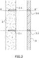
- the rigid construction (2) and the insulating layer (3) are simultaneously drilled along an axis (X-X') which result into perforating a construction hole (2.1) in the rigid construction (2) and an aligned mounting hole (3.1) in the insulating layer (3) along the axis (X-X') when said insulating layer (3) is in its operative location.
- a spacer fastening means (4) is inserted through both the mounting hole (3.1) and the construction hole (2.1) previously perforated respectively in the insulating layer (3) and the rigid construction (2) being finally fixed to the rigid construction (2).
- the spacer fastening means (4) comprises a fastening screw (4.1), preferably made of metal, and a hollow shank (4.2), and preferably made of plastic.
- the hollow shank (4.2) presents an inner cavity which provide space for lodging the fastening screw (4.1)
- the spacer fastening means (4) or a plurality of them are intended for fixing the insulating layer (3), at a predetermined distance, to a rigid construction (2).
- Said spacer fastening means (4) should be previously selected having its length long enough to respect the predetermined distance and taking into account both the depth of construction hole (2.1) and the thickness of the insulating layer (3).
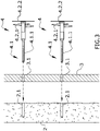
- the previously mentioned spacer fastening means also comprises an end portion, identified as threaded tip (4.1.1), and adapted to be fixed to the rigid construction (2).
- the previously mentioned hollow shank (4.2) comprises a wide helical threaded (4.2.1) ended in a plate (4.2.2).
- the helical thread (4.2.1) is screwed into the insulating layer (3) using a specific tool (not shown in this figure), which allows to rotate the hollow shank (4.2) while keeping the fastening screw (4.1) fixed into the rigid construction (2), until the plate (4.2.2) rests on the outer surface of said insulating layer (3).
- the hollow shank (4.2) is rotatable respectively to the fastening screw (4.1) but also adapted to be locked in the axial longitudinal direction of the fastening screw (4.1) thanks to axial retention.
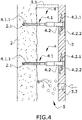
- At least a spacing means (5.1) is set between the rigid construction (5) and the insulating layer (3). Since the length of the spacing means (5.1) has been previously adjusted to the dimensions of the gap generating the insulation space (5), the resulting distance between the rigid construction (2) and the insulating layer (3) is correctly determined.
- said configuration creates an insulation space (5) between the rigid construction (2) and the insulation layer (3).
- the insulation space (5) is filled with insulation particles (6) through a previously perforated filling hole (3.3) in the insulating layer (3).
- the filling hole (3.3), perforated in the insulating layer (3), or a plurality of them are intended for filling the insulation space (5) with insulating particles as homogenously as possible.
- the insulation particles (6) filling the resultant insulation space (5) are in form of non-bonded flocs.
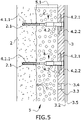
- the used filling hole (3.3) of the previous step is covered by covering means (3.4) rendering a leveled surface ready for receiving a finishing layer (3.5).
- the plurality of filling holes (3.3), previously performed on the insulating layer (3), are covered by said covering means (3.4).
- Said covering means (3.4) are pieces of the extracted portions from the previously performed filling hole (3.3) in the insulating layer (3).
- the resulting outer surface is flat, free of cavities or holes, but may show irregularities, mainly at the location of the covering means (3.4).
- the outer surface of the insulating layer (3) with the covering means (4) is covered with at least one layer of a base coat (3.2) providing a high-quality surface.
- the outer surface with the at least one layer of base coat (3.2) is covered by a finishing layer (3.5).
- a glass fiber layer is interposed improving the mechanical properties of the construction, specifically improving the resistance to external aggressions of environmental elements and the rigidity.
Landscapes
- Physics & Mathematics (AREA)
- Engineering & Computer Science (AREA)
- Architecture (AREA)
- Acoustics & Sound (AREA)
- Electromagnetism (AREA)
- Civil Engineering (AREA)
- Structural Engineering (AREA)
- Building Environments (AREA)
Priority Applications (3)
| Application Number | Priority Date | Filing Date | Title |
|---|---|---|---|
| EP20383035.1A EP4006246A1 (fr) | 2020-11-30 | 2020-11-30 | Structure isolante et procédé de fabrication d'une telle structure isolante |
| PCT/EP2021/083288 WO2022112544A1 (fr) | 2020-11-30 | 2021-11-29 | Procédé de fabrication d'une structure isolante |
| EP21823497.9A EP4251818A1 (fr) | 2020-11-30 | 2021-11-29 | Procédé de fabrication d'une structure isolante |
Applications Claiming Priority (1)
| Application Number | Priority Date | Filing Date | Title |
|---|---|---|---|
| EP20383035.1A EP4006246A1 (fr) | 2020-11-30 | 2020-11-30 | Structure isolante et procédé de fabrication d'une telle structure isolante |
Publications (1)
| Publication Number | Publication Date |
|---|---|
| EP4006246A1 true EP4006246A1 (fr) | 2022-06-01 |
Family
ID=73654764
Family Applications (2)
| Application Number | Title | Priority Date | Filing Date |
|---|---|---|---|
| EP20383035.1A Withdrawn EP4006246A1 (fr) | 2020-11-30 | 2020-11-30 | Structure isolante et procédé de fabrication d'une telle structure isolante |
| EP21823497.9A Pending EP4251818A1 (fr) | 2020-11-30 | 2021-11-29 | Procédé de fabrication d'une structure isolante |
Family Applications After (1)
| Application Number | Title | Priority Date | Filing Date |
|---|---|---|---|
| EP21823497.9A Pending EP4251818A1 (fr) | 2020-11-30 | 2021-11-29 | Procédé de fabrication d'une structure isolante |
Country Status (2)
| Country | Link |
|---|---|
| EP (2) | EP4006246A1 (fr) |
| WO (1) | WO2022112544A1 (fr) |
Citations (8)
| Publication number | Priority date | Publication date | Assignee | Title |
|---|---|---|---|---|
| US5655350A (en) * | 1994-07-18 | 1997-08-12 | Patton; Bruce L. | Method for retro-fit forming firestops in existing wall structures with blown insulation |
| EP2216454A2 (fr) | 2009-02-06 | 2010-08-11 | Unger-Diffutherm GmbH | Système d'isolation |
| EP2666919A2 (fr) | 2012-05-22 | 2013-11-27 | RANIT-Befestigungssysteme GmbH | Procédé et système de fixation pour le montage de plaques d'isolant sur une surface de support |
| AT13599U1 (de) * | 2012-08-14 | 2014-04-15 | Egger Michael Mag | Wärmedämmsystem |
| WO2014090707A1 (fr) | 2012-12-10 | 2014-06-19 | Knauf Insulation | Système d'isolation |
| EP2215317B1 (fr) | 2007-12-06 | 2015-03-11 | fischerwerke GmbH & Co. KG | Dispositif de maintien de matériau isolant et procédé de fixation d'une plaque de matériau isolant |
| EP3150772A1 (fr) | 2015-10-02 | 2017-04-05 | URSA Insulation, S.A. | Construction améliorée d'un système de mur ou de toit comprenant une isolation fibreuse |
| EP3318685A1 (fr) * | 2016-11-03 | 2018-05-09 | EJOT Baubefestigungen GmbH | Goujon d'alignement |
-
2020
- 2020-11-30 EP EP20383035.1A patent/EP4006246A1/fr not_active Withdrawn
-
2021
- 2021-11-29 WO PCT/EP2021/083288 patent/WO2022112544A1/fr unknown
- 2021-11-29 EP EP21823497.9A patent/EP4251818A1/fr active Pending
Patent Citations (8)
| Publication number | Priority date | Publication date | Assignee | Title |
|---|---|---|---|---|
| US5655350A (en) * | 1994-07-18 | 1997-08-12 | Patton; Bruce L. | Method for retro-fit forming firestops in existing wall structures with blown insulation |
| EP2215317B1 (fr) | 2007-12-06 | 2015-03-11 | fischerwerke GmbH & Co. KG | Dispositif de maintien de matériau isolant et procédé de fixation d'une plaque de matériau isolant |
| EP2216454A2 (fr) | 2009-02-06 | 2010-08-11 | Unger-Diffutherm GmbH | Système d'isolation |
| EP2666919A2 (fr) | 2012-05-22 | 2013-11-27 | RANIT-Befestigungssysteme GmbH | Procédé et système de fixation pour le montage de plaques d'isolant sur une surface de support |
| AT13599U1 (de) * | 2012-08-14 | 2014-04-15 | Egger Michael Mag | Wärmedämmsystem |
| WO2014090707A1 (fr) | 2012-12-10 | 2014-06-19 | Knauf Insulation | Système d'isolation |
| EP3150772A1 (fr) | 2015-10-02 | 2017-04-05 | URSA Insulation, S.A. | Construction améliorée d'un système de mur ou de toit comprenant une isolation fibreuse |
| EP3318685A1 (fr) * | 2016-11-03 | 2018-05-09 | EJOT Baubefestigungen GmbH | Goujon d'alignement |
Also Published As
| Publication number | Publication date |
|---|---|
| EP4251818A1 (fr) | 2023-10-04 |
| WO2022112544A1 (fr) | 2022-06-02 |
Similar Documents
| Publication | Publication Date | Title |
|---|---|---|
| US5606832A (en) | Connectors used in making highly insulated composite wall structures | |
| EP2670924B1 (fr) | Système d'isolation pour couvrir une façade d'un bâtiment | |
| EP2839085B1 (fr) | Système d'isolation destiné à recouvrir la façade d'un bâtiment | |
| EP3348725B1 (fr) | Système d'isolation comprenant des éléments d'isolation de la laine de verre et procédé amélioré de fixation espacée des éléments d'isolation | |
| EP3314066B1 (fr) | Panneau osb modifié et son utilisation dans des parois de systèmes de construction de maison | |
| DE19815170C5 (de) | Dämmstoffelement zu Wärme- und/oder Schalldämmzwecken sowie Verfahren und Vorrichtung zur Behandlung, insbesondere Beschichtung von Dämmstoffen | |
| US20130205701A1 (en) | Heat Insulation Element for Insulating Building Facades; Heat Insulation Composite System and Method for Producing a Heat Insulation Composite System | |
| EP3150772B1 (fr) | Construction améliorée d'un système de mur ou de toit comprenant une isolation fibreuse | |
| EP4006246A1 (fr) | Structure isolante et procédé de fabrication d'une telle structure isolante | |
| EP1826335A1 (fr) | Système de façade isolée | |
| CA2614522A1 (fr) | Panneau a base de stuc | |
| EP4006247A1 (fr) | Méthode pour modifier l'isolation d'une construction rigide isolée | |
| EP3150773B1 (fr) | Procédé amélioré de fixation d'un élément d'isolation pour un élément de structure d'un bâtiment et dispositif de fixation d'espacement approprié pour être utilisé dans un tel procédé | |
| JP2016204860A (ja) | 意匠パネル、壁構造及び施工方法 | |
| DE102004035249B3 (de) | Verfahren zur Herstellung eines Wärmedämmverbundsystems | |
| RU52043U1 (ru) | Кровельная плита | |
| DE19806454A1 (de) | Dämmstoffelement | |
| ES2292833T3 (es) | Esteras de fibra mineral. | |
| PL226419B1 (pl) | Sposób i urządzenie kotwiące do naprawy i układania izolacji wielowarstwowej ścian obiektów budowlanych | |
| EP0936321A2 (fr) | Elément isolant | |
| WO2001085440A1 (fr) | Panneau comprenant des fibres minerales et une resine thermodurcissable, utilisation du panneau et son procede de preparation | |
| EA045035B1 (ru) | Разделительное крепёжное устройство для крепления изоляционного элемента к конструктивному элементу здания | |
| EA040883B1 (ru) | Способ крепления изоляционного элемента к структурному элементу здания | |
| JP2000282599A (ja) | 外壁の防火構造 |
Legal Events
| Date | Code | Title | Description |
|---|---|---|---|
| PUAI | Public reference made under article 153(3) epc to a published international application that has entered the european phase |
Free format text: ORIGINAL CODE: 0009012 |
|
| STAA | Information on the status of an ep patent application or granted ep patent |
Free format text: STATUS: THE APPLICATION HAS BEEN PUBLISHED |
|
| AK | Designated contracting states |
Kind code of ref document: A1 Designated state(s): AL AT BE BG CH CY CZ DE DK EE ES FI FR GB GR HR HU IE IS IT LI LT LU LV MC MK MT NL NO PL PT RO RS SE SI SK SM TR |
|
| STAA | Information on the status of an ep patent application or granted ep patent |
Free format text: STATUS: REQUEST FOR EXAMINATION WAS MADE |
|
| 17P | Request for examination filed |
Effective date: 20221130 |
|
| RBV | Designated contracting states (corrected) |
Designated state(s): AL AT BE BG CH CY CZ DE DK EE ES FI FR GB GR HR HU IE IS IT LI LT LU LV MC MK MT NL NO PL PT RO RS SE SI SK SM TR |
|
| STAA | Information on the status of an ep patent application or granted ep patent |
Free format text: STATUS: THE APPLICATION HAS BEEN WITHDRAWN |
|
| 18W | Application withdrawn |
Effective date: 20230622 |