EP4005841A2 - Lower structure of vehicle - Google Patents
Lower structure of vehicle Download PDFInfo
- Publication number
- EP4005841A2 EP4005841A2 EP21207202.9A EP21207202A EP4005841A2 EP 4005841 A2 EP4005841 A2 EP 4005841A2 EP 21207202 A EP21207202 A EP 21207202A EP 4005841 A2 EP4005841 A2 EP 4005841A2
- Authority
- EP
- European Patent Office
- Prior art keywords
- vehicle
- planar
- mount
- rear direction
- protector
- Prior art date
- Legal status (The legal status is an assumption and is not a legal conclusion. Google has not performed a legal analysis and makes no representation as to the accuracy of the status listed.)
- Granted
Links
Images




Classifications
-
- B—PERFORMING OPERATIONS; TRANSPORTING
- B60—VEHICLES IN GENERAL
- B60K—ARRANGEMENT OR MOUNTING OF PROPULSION UNITS OR OF TRANSMISSIONS IN VEHICLES; ARRANGEMENT OR MOUNTING OF PLURAL DIVERSE PRIME-MOVERS IN VEHICLES; AUXILIARY DRIVES FOR VEHICLES; INSTRUMENTATION OR DASHBOARDS FOR VEHICLES; ARRANGEMENTS IN CONNECTION WITH COOLING, AIR INTAKE, GAS EXHAUST OR FUEL SUPPLY OF PROPULSION UNITS IN VEHICLES
- B60K6/00—Arrangement or mounting of plural diverse prime-movers for mutual or common propulsion, e.g. hybrid propulsion systems comprising electric motors and internal combustion engines
- B60K6/20—Arrangement or mounting of plural diverse prime-movers for mutual or common propulsion, e.g. hybrid propulsion systems comprising electric motors and internal combustion engines the prime-movers consisting of electric motors and internal combustion engines, e.g. HEVs
- B60K6/22—Arrangement or mounting of plural diverse prime-movers for mutual or common propulsion, e.g. hybrid propulsion systems comprising electric motors and internal combustion engines the prime-movers consisting of electric motors and internal combustion engines, e.g. HEVs characterised by apparatus, components or means specially adapted for HEVs
- B60K6/28—Arrangement or mounting of plural diverse prime-movers for mutual or common propulsion, e.g. hybrid propulsion systems comprising electric motors and internal combustion engines the prime-movers consisting of electric motors and internal combustion engines, e.g. HEVs characterised by apparatus, components or means specially adapted for HEVs characterised by the electric energy storing means, e.g. batteries or capacitors
-
- B—PERFORMING OPERATIONS; TRANSPORTING
- B60—VEHICLES IN GENERAL
- B60K—ARRANGEMENT OR MOUNTING OF PROPULSION UNITS OR OF TRANSMISSIONS IN VEHICLES; ARRANGEMENT OR MOUNTING OF PLURAL DIVERSE PRIME-MOVERS IN VEHICLES; AUXILIARY DRIVES FOR VEHICLES; INSTRUMENTATION OR DASHBOARDS FOR VEHICLES; ARRANGEMENTS IN CONNECTION WITH COOLING, AIR INTAKE, GAS EXHAUST OR FUEL SUPPLY OF PROPULSION UNITS IN VEHICLES
- B60K17/00—Arrangement or mounting of transmissions in vehicles
- B60K17/22—Arrangement or mounting of transmissions in vehicles characterised by arrangement, location, or type of main drive shafting, e.g. cardan shaft
- B60K17/24—Arrangement of mountings for shafting
-
- B—PERFORMING OPERATIONS; TRANSPORTING
- B60—VEHICLES IN GENERAL
- B60K—ARRANGEMENT OR MOUNTING OF PROPULSION UNITS OR OF TRANSMISSIONS IN VEHICLES; ARRANGEMENT OR MOUNTING OF PLURAL DIVERSE PRIME-MOVERS IN VEHICLES; AUXILIARY DRIVES FOR VEHICLES; INSTRUMENTATION OR DASHBOARDS FOR VEHICLES; ARRANGEMENTS IN CONNECTION WITH COOLING, AIR INTAKE, GAS EXHAUST OR FUEL SUPPLY OF PROPULSION UNITS IN VEHICLES
- B60K1/00—Arrangement or mounting of electrical propulsion units
- B60K1/04—Arrangement or mounting of electrical propulsion units of the electric storage means for propulsion
-
- B—PERFORMING OPERATIONS; TRANSPORTING
- B60—VEHICLES IN GENERAL
- B60K—ARRANGEMENT OR MOUNTING OF PROPULSION UNITS OR OF TRANSMISSIONS IN VEHICLES; ARRANGEMENT OR MOUNTING OF PLURAL DIVERSE PRIME-MOVERS IN VEHICLES; AUXILIARY DRIVES FOR VEHICLES; INSTRUMENTATION OR DASHBOARDS FOR VEHICLES; ARRANGEMENTS IN CONNECTION WITH COOLING, AIR INTAKE, GAS EXHAUST OR FUEL SUPPLY OF PROPULSION UNITS IN VEHICLES
- B60K17/00—Arrangement or mounting of transmissions in vehicles
- B60K17/22—Arrangement or mounting of transmissions in vehicles characterised by arrangement, location, or type of main drive shafting, e.g. cardan shaft
-
- B—PERFORMING OPERATIONS; TRANSPORTING
- B60—VEHICLES IN GENERAL
- B60K—ARRANGEMENT OR MOUNTING OF PROPULSION UNITS OR OF TRANSMISSIONS IN VEHICLES; ARRANGEMENT OR MOUNTING OF PLURAL DIVERSE PRIME-MOVERS IN VEHICLES; AUXILIARY DRIVES FOR VEHICLES; INSTRUMENTATION OR DASHBOARDS FOR VEHICLES; ARRANGEMENTS IN CONNECTION WITH COOLING, AIR INTAKE, GAS EXHAUST OR FUEL SUPPLY OF PROPULSION UNITS IN VEHICLES
- B60K17/00—Arrangement or mounting of transmissions in vehicles
- B60K17/34—Arrangement or mounting of transmissions in vehicles for driving both front and rear wheels, e.g. four wheel drive vehicles
-
- B—PERFORMING OPERATIONS; TRANSPORTING
- B60—VEHICLES IN GENERAL
- B60K—ARRANGEMENT OR MOUNTING OF PROPULSION UNITS OR OF TRANSMISSIONS IN VEHICLES; ARRANGEMENT OR MOUNTING OF PLURAL DIVERSE PRIME-MOVERS IN VEHICLES; AUXILIARY DRIVES FOR VEHICLES; INSTRUMENTATION OR DASHBOARDS FOR VEHICLES; ARRANGEMENTS IN CONNECTION WITH COOLING, AIR INTAKE, GAS EXHAUST OR FUEL SUPPLY OF PROPULSION UNITS IN VEHICLES
- B60K6/00—Arrangement or mounting of plural diverse prime-movers for mutual or common propulsion, e.g. hybrid propulsion systems comprising electric motors and internal combustion engines
- B60K6/20—Arrangement or mounting of plural diverse prime-movers for mutual or common propulsion, e.g. hybrid propulsion systems comprising electric motors and internal combustion engines the prime-movers consisting of electric motors and internal combustion engines, e.g. HEVs
- B60K6/22—Arrangement or mounting of plural diverse prime-movers for mutual or common propulsion, e.g. hybrid propulsion systems comprising electric motors and internal combustion engines the prime-movers consisting of electric motors and internal combustion engines, e.g. HEVs characterised by apparatus, components or means specially adapted for HEVs
- B60K6/36—Arrangement or mounting of plural diverse prime-movers for mutual or common propulsion, e.g. hybrid propulsion systems comprising electric motors and internal combustion engines the prime-movers consisting of electric motors and internal combustion engines, e.g. HEVs characterised by apparatus, components or means specially adapted for HEVs characterised by the transmission gearings
-
- B—PERFORMING OPERATIONS; TRANSPORTING
- B60—VEHICLES IN GENERAL
- B60K—ARRANGEMENT OR MOUNTING OF PROPULSION UNITS OR OF TRANSMISSIONS IN VEHICLES; ARRANGEMENT OR MOUNTING OF PLURAL DIVERSE PRIME-MOVERS IN VEHICLES; AUXILIARY DRIVES FOR VEHICLES; INSTRUMENTATION OR DASHBOARDS FOR VEHICLES; ARRANGEMENTS IN CONNECTION WITH COOLING, AIR INTAKE, GAS EXHAUST OR FUEL SUPPLY OF PROPULSION UNITS IN VEHICLES
- B60K6/00—Arrangement or mounting of plural diverse prime-movers for mutual or common propulsion, e.g. hybrid propulsion systems comprising electric motors and internal combustion engines
- B60K6/20—Arrangement or mounting of plural diverse prime-movers for mutual or common propulsion, e.g. hybrid propulsion systems comprising electric motors and internal combustion engines the prime-movers consisting of electric motors and internal combustion engines, e.g. HEVs
- B60K6/22—Arrangement or mounting of plural diverse prime-movers for mutual or common propulsion, e.g. hybrid propulsion systems comprising electric motors and internal combustion engines the prime-movers consisting of electric motors and internal combustion engines, e.g. HEVs characterised by apparatus, components or means specially adapted for HEVs
- B60K6/40—Arrangement or mounting of plural diverse prime-movers for mutual or common propulsion, e.g. hybrid propulsion systems comprising electric motors and internal combustion engines the prime-movers consisting of electric motors and internal combustion engines, e.g. HEVs characterised by apparatus, components or means specially adapted for HEVs characterised by the assembly or relative disposition of components
-
- B—PERFORMING OPERATIONS; TRANSPORTING
- B60—VEHICLES IN GENERAL
- B60K—ARRANGEMENT OR MOUNTING OF PROPULSION UNITS OR OF TRANSMISSIONS IN VEHICLES; ARRANGEMENT OR MOUNTING OF PLURAL DIVERSE PRIME-MOVERS IN VEHICLES; AUXILIARY DRIVES FOR VEHICLES; INSTRUMENTATION OR DASHBOARDS FOR VEHICLES; ARRANGEMENTS IN CONNECTION WITH COOLING, AIR INTAKE, GAS EXHAUST OR FUEL SUPPLY OF PROPULSION UNITS IN VEHICLES
- B60K6/00—Arrangement or mounting of plural diverse prime-movers for mutual or common propulsion, e.g. hybrid propulsion systems comprising electric motors and internal combustion engines
- B60K6/20—Arrangement or mounting of plural diverse prime-movers for mutual or common propulsion, e.g. hybrid propulsion systems comprising electric motors and internal combustion engines the prime-movers consisting of electric motors and internal combustion engines, e.g. HEVs
- B60K6/42—Arrangement or mounting of plural diverse prime-movers for mutual or common propulsion, e.g. hybrid propulsion systems comprising electric motors and internal combustion engines the prime-movers consisting of electric motors and internal combustion engines, e.g. HEVs characterised by the architecture of the hybrid electric vehicle
- B60K6/48—Parallel type
-
- B—PERFORMING OPERATIONS; TRANSPORTING
- B60—VEHICLES IN GENERAL
- B60K—ARRANGEMENT OR MOUNTING OF PROPULSION UNITS OR OF TRANSMISSIONS IN VEHICLES; ARRANGEMENT OR MOUNTING OF PLURAL DIVERSE PRIME-MOVERS IN VEHICLES; AUXILIARY DRIVES FOR VEHICLES; INSTRUMENTATION OR DASHBOARDS FOR VEHICLES; ARRANGEMENTS IN CONNECTION WITH COOLING, AIR INTAKE, GAS EXHAUST OR FUEL SUPPLY OF PROPULSION UNITS IN VEHICLES
- B60K6/00—Arrangement or mounting of plural diverse prime-movers for mutual or common propulsion, e.g. hybrid propulsion systems comprising electric motors and internal combustion engines
- B60K6/20—Arrangement or mounting of plural diverse prime-movers for mutual or common propulsion, e.g. hybrid propulsion systems comprising electric motors and internal combustion engines the prime-movers consisting of electric motors and internal combustion engines, e.g. HEVs
- B60K6/50—Architecture of the driveline characterised by arrangement or kind of transmission units
- B60K6/52—Driving a plurality of drive axles, e.g. four-wheel drive
-
- B—PERFORMING OPERATIONS; TRANSPORTING
- B60—VEHICLES IN GENERAL
- B60L—PROPULSION OF ELECTRICALLY-PROPELLED VEHICLES; SUPPLYING ELECTRIC POWER FOR AUXILIARY EQUIPMENT OF ELECTRICALLY-PROPELLED VEHICLES; ELECTRODYNAMIC BRAKE SYSTEMS FOR VEHICLES IN GENERAL; MAGNETIC SUSPENSION OR LEVITATION FOR VEHICLES; MONITORING OPERATING VARIABLES OF ELECTRICALLY-PROPELLED VEHICLES; ELECTRIC SAFETY DEVICES FOR ELECTRICALLY-PROPELLED VEHICLES
- B60L3/00—Electric devices on electrically-propelled vehicles for safety purposes; Monitoring operating variables, e.g. speed, deceleration or energy consumption
- B60L3/0007—Measures or means for preventing or attenuating collisions
-
- B—PERFORMING OPERATIONS; TRANSPORTING
- B60—VEHICLES IN GENERAL
- B60L—PROPULSION OF ELECTRICALLY-PROPELLED VEHICLES; SUPPLYING ELECTRIC POWER FOR AUXILIARY EQUIPMENT OF ELECTRICALLY-PROPELLED VEHICLES; ELECTRODYNAMIC BRAKE SYSTEMS FOR VEHICLES IN GENERAL; MAGNETIC SUSPENSION OR LEVITATION FOR VEHICLES; MONITORING OPERATING VARIABLES OF ELECTRICALLY-PROPELLED VEHICLES; ELECTRIC SAFETY DEVICES FOR ELECTRICALLY-PROPELLED VEHICLES
- B60L50/00—Electric propulsion with power supplied within the vehicle
- B60L50/50—Electric propulsion with power supplied within the vehicle using propulsion power supplied by batteries or fuel cells
- B60L50/60—Electric propulsion with power supplied within the vehicle using propulsion power supplied by batteries or fuel cells using power supplied by batteries
- B60L50/64—Constructional details of batteries specially adapted for electric vehicles
-
- B—PERFORMING OPERATIONS; TRANSPORTING
- B60—VEHICLES IN GENERAL
- B60L—PROPULSION OF ELECTRICALLY-PROPELLED VEHICLES; SUPPLYING ELECTRIC POWER FOR AUXILIARY EQUIPMENT OF ELECTRICALLY-PROPELLED VEHICLES; ELECTRODYNAMIC BRAKE SYSTEMS FOR VEHICLES IN GENERAL; MAGNETIC SUSPENSION OR LEVITATION FOR VEHICLES; MONITORING OPERATING VARIABLES OF ELECTRICALLY-PROPELLED VEHICLES; ELECTRIC SAFETY DEVICES FOR ELECTRICALLY-PROPELLED VEHICLES
- B60L50/00—Electric propulsion with power supplied within the vehicle
- B60L50/50—Electric propulsion with power supplied within the vehicle using propulsion power supplied by batteries or fuel cells
- B60L50/60—Electric propulsion with power supplied within the vehicle using propulsion power supplied by batteries or fuel cells using power supplied by batteries
- B60L50/66—Arrangements of batteries
-
- H—ELECTRICITY
- H01—ELECTRIC ELEMENTS
- H01M—PROCESSES OR MEANS, e.g. BATTERIES, FOR THE DIRECT CONVERSION OF CHEMICAL ENERGY INTO ELECTRICAL ENERGY
- H01M50/00—Constructional details or processes of manufacture of the non-active parts of electrochemical cells other than fuel cells, e.g. hybrid cells
- H01M50/20—Mountings; Secondary casings or frames; Racks, modules or packs; Suspension devices; Shock absorbers; Transport or carrying devices; Holders
- H01M50/204—Racks, modules or packs for multiple batteries or multiple cells
- H01M50/207—Racks, modules or packs for multiple batteries or multiple cells characterised by their shape
-
- H—ELECTRICITY
- H01—ELECTRIC ELEMENTS
- H01M—PROCESSES OR MEANS, e.g. BATTERIES, FOR THE DIRECT CONVERSION OF CHEMICAL ENERGY INTO ELECTRICAL ENERGY
- H01M50/00—Constructional details or processes of manufacture of the non-active parts of electrochemical cells other than fuel cells, e.g. hybrid cells
- H01M50/20—Mountings; Secondary casings or frames; Racks, modules or packs; Suspension devices; Shock absorbers; Transport or carrying devices; Holders
- H01M50/244—Secondary casings; Racks; Suspension devices; Carrying devices; Holders characterised by their mounting method
-
- H—ELECTRICITY
- H01—ELECTRIC ELEMENTS
- H01M—PROCESSES OR MEANS, e.g. BATTERIES, FOR THE DIRECT CONVERSION OF CHEMICAL ENERGY INTO ELECTRICAL ENERGY
- H01M50/00—Constructional details or processes of manufacture of the non-active parts of electrochemical cells other than fuel cells, e.g. hybrid cells
- H01M50/20—Mountings; Secondary casings or frames; Racks, modules or packs; Suspension devices; Shock absorbers; Transport or carrying devices; Holders
- H01M50/249—Mountings; Secondary casings or frames; Racks, modules or packs; Suspension devices; Shock absorbers; Transport or carrying devices; Holders specially adapted for aircraft or vehicles, e.g. cars or trains
-
- B—PERFORMING OPERATIONS; TRANSPORTING
- B60—VEHICLES IN GENERAL
- B60K—ARRANGEMENT OR MOUNTING OF PROPULSION UNITS OR OF TRANSMISSIONS IN VEHICLES; ARRANGEMENT OR MOUNTING OF PLURAL DIVERSE PRIME-MOVERS IN VEHICLES; AUXILIARY DRIVES FOR VEHICLES; INSTRUMENTATION OR DASHBOARDS FOR VEHICLES; ARRANGEMENTS IN CONNECTION WITH COOLING, AIR INTAKE, GAS EXHAUST OR FUEL SUPPLY OF PROPULSION UNITS IN VEHICLES
- B60K1/00—Arrangement or mounting of electrical propulsion units
- B60K1/04—Arrangement or mounting of electrical propulsion units of the electric storage means for propulsion
- B60K2001/0405—Arrangement or mounting of electrical propulsion units of the electric storage means for propulsion characterised by their position
- B60K2001/0438—Arrangement under the floor
-
- B—PERFORMING OPERATIONS; TRANSPORTING
- B60—VEHICLES IN GENERAL
- B60K—ARRANGEMENT OR MOUNTING OF PROPULSION UNITS OR OF TRANSMISSIONS IN VEHICLES; ARRANGEMENT OR MOUNTING OF PLURAL DIVERSE PRIME-MOVERS IN VEHICLES; AUXILIARY DRIVES FOR VEHICLES; INSTRUMENTATION OR DASHBOARDS FOR VEHICLES; ARRANGEMENTS IN CONNECTION WITH COOLING, AIR INTAKE, GAS EXHAUST OR FUEL SUPPLY OF PROPULSION UNITS IN VEHICLES
- B60K6/00—Arrangement or mounting of plural diverse prime-movers for mutual or common propulsion, e.g. hybrid propulsion systems comprising electric motors and internal combustion engines
- B60K6/20—Arrangement or mounting of plural diverse prime-movers for mutual or common propulsion, e.g. hybrid propulsion systems comprising electric motors and internal combustion engines the prime-movers consisting of electric motors and internal combustion engines, e.g. HEVs
- B60K6/42—Arrangement or mounting of plural diverse prime-movers for mutual or common propulsion, e.g. hybrid propulsion systems comprising electric motors and internal combustion engines the prime-movers consisting of electric motors and internal combustion engines, e.g. HEVs characterised by the architecture of the hybrid electric vehicle
- B60K6/48—Parallel type
- B60K2006/4825—Electric machine connected or connectable to gearbox input shaft
-
- B—PERFORMING OPERATIONS; TRANSPORTING
- B60—VEHICLES IN GENERAL
- B60Y—INDEXING SCHEME RELATING TO ASPECTS CROSS-CUTTING VEHICLE TECHNOLOGY
- B60Y2306/00—Other features of vehicle sub-units
- B60Y2306/01—Reducing damages in case of crash, e.g. by improving battery protection
-
- H—ELECTRICITY
- H01—ELECTRIC ELEMENTS
- H01M—PROCESSES OR MEANS, e.g. BATTERIES, FOR THE DIRECT CONVERSION OF CHEMICAL ENERGY INTO ELECTRICAL ENERGY
- H01M2220/00—Batteries for particular applications
- H01M2220/20—Batteries in motive systems, e.g. vehicle, ship, plane
-
- Y—GENERAL TAGGING OF NEW TECHNOLOGICAL DEVELOPMENTS; GENERAL TAGGING OF CROSS-SECTIONAL TECHNOLOGIES SPANNING OVER SEVERAL SECTIONS OF THE IPC; TECHNICAL SUBJECTS COVERED BY FORMER USPC CROSS-REFERENCE ART COLLECTIONS [XRACs] AND DIGESTS
- Y02—TECHNOLOGIES OR APPLICATIONS FOR MITIGATION OR ADAPTATION AGAINST CLIMATE CHANGE
- Y02E—REDUCTION OF GREENHOUSE GAS [GHG] EMISSIONS, RELATED TO ENERGY GENERATION, TRANSMISSION OR DISTRIBUTION
- Y02E60/00—Enabling technologies; Technologies with a potential or indirect contribution to GHG emissions mitigation
- Y02E60/10—Energy storage using batteries
-
- Y—GENERAL TAGGING OF NEW TECHNOLOGICAL DEVELOPMENTS; GENERAL TAGGING OF CROSS-SECTIONAL TECHNOLOGIES SPANNING OVER SEVERAL SECTIONS OF THE IPC; TECHNICAL SUBJECTS COVERED BY FORMER USPC CROSS-REFERENCE ART COLLECTIONS [XRACs] AND DIGESTS
- Y02—TECHNOLOGIES OR APPLICATIONS FOR MITIGATION OR ADAPTATION AGAINST CLIMATE CHANGE
- Y02T—CLIMATE CHANGE MITIGATION TECHNOLOGIES RELATED TO TRANSPORTATION
- Y02T10/00—Road transport of goods or passengers
- Y02T10/60—Other road transportation technologies with climate change mitigation effect
- Y02T10/62—Hybrid vehicles
Definitions
- the present disclosure relates to a lower structure of a vehicle.
- Patent document 1 discloses an example of the lower structure of a vehicle. Specifically, patent document 1 discloses a vehicle including a propeller shaft that extends from the rear end portion of a transmission toward the vehicle rear and transmits power to the rear wheels, and battery packs disposed below the floor panels on the left and right sides of a floor tunnel.
- the left and right battery packs are spaced apart in the vehicle width direction.
- the propeller shaft is laid out so as to be disposed between the left and right battery packs in the vehicle width direction, more accurately between the inner side surface portions of the battery packs.
- the propeller shaft configured as described above may include two shaft portions connected to each other via a joint portion including a so-called universal joint or the like.
- the propeller shaft is bent starting from the joint portion, whereby the gearbox can move backward more smoothly without suffering interference.
- the backward movement of the gearbox is effective in ensuring the crash stroke of the vehicle body.
- the present disclosure addresses the problem described above with an object of satisfactorily protecting the left and right battery units without interfering with the backward movement of the gearbox.
- a first aspect of the present disclosure relates to a lower structure of a vehicle in which a rear wheel serves as a drive wheel.
- the vehicle includes a gearbox disposed with at least a portion thereof present in a floor tunnel, the portion being present on a vehicle rear side of the gearbox; a propeller shaft that extends from the gearbox toward the vehicle rear side, the propeller shaft transmitting power to the rear wheel; and left and right battery units disposed on a vehicle lower side of left and right floor panels, the left and right floor panels being disposed on a vehicle left side and a vehicle right side of the floor tunnel, in which the propeller shaft has a first shaft portion and a second shaft portion that are arranged in sequence from a vehicle front side, the first shaft portion being connected to the gear box, the second shaft portion being connected to the first shaft portion via a joint portion, each of the left and right battery units has an inner side surface portion that extends along an inner wall portion of the floor tunnel and faces an inner side in a vehicle width direction, and a planar protector that covers
- the propeller shaft bends starting from the joint portion, whereby the gearbox can move backward smoothly.
- the joint portion with which the bending starts may be disadvantageously displaced to the left and right while moving backward.
- the contact between the joint portion and the battery units can be suppressed by covering the portion located on the vehicle rear side of the joint portion with the protector. This can satisfactorily protect the left and right battery units without interfering with the backward movement of the gearbox.
- the protector may include a plate portion that extends in a vehicle front-rear direction and a vehicle height direction, a first mount portion that is provided in a circumferential edge portion of the plate portion and connected to a vehicle body structural component of the vehicle, and a second mount portion that is provided in the circumferential edge portion of the plate portion and connected to one of the left and right battery units, and dimensions in the vehicle front-rear direction of the first mount portion and the second mount portion may be smaller than a dimension in the vehicle front-rear direction of the plate portion.
- the left and right battery units can be protected more reliably by setting the dimension of the plate portion of the protector that suppresses contact with the battery units to be relatively larger.
- the weight of the protectors can be reduced advantageously by setting the dimensions of the first mount portion and the second mount portion to be relatively smaller. This can reduce the weight of the protectors as much as possible while ensuring the protection performance for the battery units.
- the first mount portion may be connected to a tunnel panel of the vehicle.
- the tunnel panel forms the floor tunnel, in particular the upper end portion of the tunnel panel may be inclined to the lower side from the front side toward the rear side. Accordingly, the floor tunnel 10 is narrower in the up-down direction toward the rear side.
- On the tunnel panel at least of reinforcement may be provided for reinforcement of the tunnel.
- the first mount portion may then be connected to an upper tunnel reinforcement.
- the first mount portion may be disposed at a middle position in the vehicle front-rear direction of the plate portion or at least close to the middle portion of the plate portion.
- the plate portion may be provided with a bead portion that extends in the vehicle front-rear direction.
- the bending of the plate portion about the central axis that extends in the vehicle height direction can be suppressed advantageously by providing the bead portion that extends in the vehicle front-rear direction in the plate portion.
- the protector may include a further second plate portion
- the plate portions (71, 72) may include two planar bodies stacked in the vehicle width direction
- the bead portion may be provided on each of the two planar bodies
- the bead portion on one planar body of the two planar bodies may be a first bead portion that projects toward the inner side in the vehicle width direction, the one planar body being located on an inner side in the vehicle width direction
- the bead portion on one planar body of the two planar bodies may be a second bead portion that projects toward the outer side in the vehicle width direction
- the one planar body being located on an outer side in the vehicle width direction
- the first bead portion and the second bead portion may be disposed so as to face each other.
- the first bead portion and the second bead portion define a closed cross section when seen in a cross section orthogonal to the vehicle front-rear direction.
- the plate portion may be formed of a rectangular shape having a larger dimension in the vehicle front-rear direction than in the vehicle height direction and the second plate portion is preferably formed in a rectangular shape having substantially the same dimensions as the first plate portion.
- the bead portion may include a plurality of bead shapes disposed in the up-down direction.
- the circumferential edge portion of the plate portion may be bent toward the inner side in the vehicle width direction, and the first mount portion and the second mount portion may be formed integrally with the bent circumferential edge portion of the plate portion.
- the distortion of the plate portion can be suppressed by bending the circumferential edge portion of the plate portion.
- the deformation of the first and the second mount portions can be suppressed advantageously by forming the first mount portion and the second mount portion in the portion bent in this way.
- the propeller shaft may be disposed above the left and right battery units in the vehicle height direction when seen in a cross section passing through at least the protector, each of the left and right battery units may be configured by fastening a pair of upper and lower case members, the case members may be formed in box shapes having openings that are open toward a vehicle upper side or the vehicle lower side and have a flanges provided along circumferential edges of the openings, the case members may be fastened to each other by inserting fasteners into the flanges, and the protector may extend upward from each of the flanges.
- the protector is configured to extend upward from the flange for connecting the case members to each other.
- the flange can be used as the mounting position of the protector while the battery units are protected by the protector. This can lay out the protector more appropriately while ensuring the protection performance for the battery units.
- a protector that is easier to mold can be used by configuring the protector so as to extend from the flange. This contributes to the improvement of the moldability of the protector.
- planar protector can be made of a high tensile steel plate.
- the dimension of the planar protector in the vehicle front-rear direction is larger than the dimension of the universal joint in the vehicle front-rear direction. Additionally or alternatively, the dimension of the planar protector in the vehicle height direction is larger than the height of the upper case member. The preferred dimension of the protector protects a sufficient area of the battery unit that can be hit by the joint portion of the shaft.
- the planar protector protects the battery unit from being hit by the shaft or joint portion of the shaft during a collision.
- the protector serves as a bracket for mounting the battery unit to the vehicle structure.
- the left and right battery units can be satisfactorily protected without interfering with the backward movement of the gearbox.
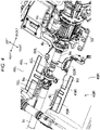
- Fig. 1 is a schematic diagram illustrating a driving system of a vehicle 1 to which a lower structure of a vehicle according to the present disclosure has been applied.
- Fig. 2 is a bottom view illustrating the structure of a front side portion of the vehicle 1 as seen from below.
- front refers to the front side in the vehicle front-rear direction and “rear” refers to the rear side in the vehicle front-rear direction.
- upper refers to the upper side in the vehicle height direction and “lower” refers to the lower side in the vehicle height direction.
- vehicle front-rear direction may be simply referred to as the "front-rear direction”
- vehicle height direction may be simply referred to as the “up-down direction”
- vehicle width direction may be simply referred to as the "left-right direction”.
- left and right in the following description are also defined with reference to the vehicle 1. That is, in the following description, “left” refers to the left side in the vehicle width direction when the vehicle 1 is seen from the rear side to the front side, and “right” refers to the right side when the vehicle 1 is seen from the rear side to the front side.
- the vehicle 1 illustrated in Fig. 1 is a hybrid vehicle. Specifically, as illustrated in Fig. 1 , the vehicle 1 includes an engine 2 and a motor 3 as drive sources (power trains) and a transmission 4 that changes the speed of a driving force transmitted from at least one of the engine 2 and the motor 3 and transmits the driving force.
- the engine 2 is housed in an engine room disposed in front of a vehicle interior.
- the engine 2 is vertically mounted at a substantially middle position in the vehicle width direction in the engine room.
- the motor 3 is disposed behind the engine 2 via a damper 5.
- the transmission 4 is vertically mounted behind the motor 3.
- the vehicle 1 has at least left and right rear wheels 7 as driving wheels. More specifically, the vehicle 1 is configured as a four-wheel-drive vehicle that has left and right front wheels 6 and the left and right rear wheels 7 as driving wheels.
- the rear portion of the transmission 4 is a transfer 4a that transmits the driving force to the front wheels 6 and the rear wheels 7.
- a front propeller shaft 8 extends toward the front side from the transfer 4a.
- a rear propeller shaft 9 extends toward the rear side from the transfer 4a.
- the front propeller shaft 8 is disposed slightly to the right of the middle in the vehicle width direction.
- the rear propeller shaft 9 is disposed substantially in the middle in the vehicle width direction.
- the driving force changed in speed by the transmission 4 is transmitted to the front propeller shaft 8 and the rear propeller shaft 9 via the transfer 4a.
- the front propeller shaft 8 transmits the driving force to the front wheels 6 and the rear propeller shaft 9 transmits the driving force to the rear wheels 7.
- the rear propeller shaft 9 is an example of the "propeller shaft" in the embodiment.
- the transmission 4 is disposed with at least the portion thereof on the vehicle rear side present in a floor tunnel 10. More specifically, the transmission 4 is disposed so as to be inclined to the lower side from the front side toward the rear side.
- the floor tunnel 10 is formed by a tunnel panel 11. As illustrated in Fig. 3 , the upper end portion of the tunnel panel 11 is inclined to the lower side from the front side toward the rear side. Accordingly, the floor tunnel 10 is narrower in the up-down direction toward the rear side.
- the rear propeller shaft 9 is disposed in the floor tunnel 10.
- the rear propeller shaft 9 is connected to the transfer 4a via a rubber cup 4b.
- the rear propeller shaft 9 extends from the position of the rubber cup 4b toward the rear side while being inclined to the lower side.
- a universal joint 9a is provided at the middle position in the front-rear direction of the rear propeller shaft 9.
- the rear propeller shaft 9 bends in the up-down direction and the left-right direction starting from the universal joint 9a at the time of, for example, a front collision.
- the universal joint 9a is an example of the "joint portion" in the embodiment.
- the rear propeller shaft 9 is divided into two portions in the front-rear direction by the universal joint 9a. Specifically, the rear propeller shaft 9 has a first shaft portion 9b connected to the transmission 4 and a second shaft portion 9c connected to the first shaft portion 9b via the universal joint 9a that are arranged in sequence from the vehicle front side.
- a support bracket 9d that supports the rear propeller shaft 9 is provided at the position of this rubber cup.
- the support bracket 9d has a U-shape that covers the rubber cup from below and the left and right end portions thereof are connected to an upper tunnel reinforcement 12 for reinforcement provided on the tunnel panel 11 with bolts.
- Side tunnel reinforcements 13 that extend in the front-rear direction are provided in the left and right end portions of the tunnel panel 11, respectively.
- the side tunnel reinforcements 13 are members for reinforcing the tunnel panel 11.
- the side tunnel reinforcements 13 are connected to the inner portion of the tunnel panel 11 by welding so as to form closed cross sections between the side tunnel reinforcements 13 and the tunnel panel 11.
- a pair of left and right floor panels 30 constituting the floor of the vehicle interior are disposed on the vehicle left side and the vehicle right side of the tunnel panel 11, respectively.
- the floor panels 30 extend horizontally in the front-rear direction and the left-right direction.
- the right end portion of the left floor panel 30 is connected to the left end portion of the tunnel panel 11 by welding.
- the left end portion of the right floor panel 30 is connected to the right end portion of the tunnel panel 11 by welding.
- the left and right floor panels 30 are connected to each other in the left-right direction by the tunnel panel 11.
- the connection portions between the floor panels 30 and the tunnel panel 11 are located at the same positions as the connection portions between the tunnel panel 11 and the side tunnel reinforcements 13 or located on the outer side in the vehicle width direction of the connection portions between the tunnel panel 11 and the side tunnel reinforcements 13.
- left and right toe boards 32 are connected to the front end portions of the left and right floor panels 30 by welding, respectively.
- the left and right toe boards 32 extend from the front end portions of the left and right floor panels 30 toward the front side while being inclined upward.
- the upper end portions of the left and right toe boards 32 are joined to the lower end portion of a dash panel (not illustrated) that separates the vehicle interior from the engine room.
- the right end portion of the left toe board 32 is connected to the left end portion of the tunnel panel 11 by welding.
- the left end portion of the right toe board 32 is connected to the right end portion of the tunnel panel 11 by welding.
- a pair of left and right floor frames 21 that extend in the front-rear direction are connected to the lower surfaces of the left and right floor panels 30 and the lower surfaces of the left and right toe boards 32, respectively.
- the left and right floor frames 21 extend toward the rear side while being inclined to the outer side in the vehicle width direction so as to be separated from each other in the vehicle width direction, and then extend straight toward the rear side in parallel to each other.
- a pair of left and right side sills 22 that extend in the front-rear direction are connected to the outer end portions in the vehicle width direction of the left and right floor panels 30.
- the left and right side sills 22 are located on the outer side in the vehicle width direction of the left and right floor frames 21.
- the left side sill 22 is connected to the left end portion of the left floor panel 30 by welding.
- the right side sill 22 is connected to the right end portion of the right floor panel 30 by welding.
- the front end portions of the left and right floor frames 21 are connected to the front end portions of the left and right side sills 22 via left and right gussets 23, respectively.
- left and right battery units 40L and 40R in which power for driving the motor 3 is stored are disposed on the left and right sides of the floor tunnel 10 in the area behind the transfer 4a.
- the battery units 40L and 40R according to the embodiment are disposed on the vehicle lower side of the floor panels 30 disposed on the vehicle left side of and the vehicle right side of the floor tunnel 10.
- the left battery unit 40L is disposed below the passenger seat and the right battery unit 40R is disposed below the driver seat.
- the left and right battery units 40L and 40R are electrically connected to each other by a connector.
- the right end portion of the left battery unit 40L and the left end portion of the right battery unit 40R slightly overlap the floor tunnel 10 when seen from above or below in the up-down direction.
- Both the left and right battery units 40L and 40R extend so as to pass through the position of the center of gravity of the vehicle 1 in the vehicle front-rear direction.
- the position of the center of gravity of the vehicle 1 is located between the front end portions and the rear end portions of the left and right battery units 40L and 40R in the vehicle front-rear direction. Such disposition makes the positions of the centers of gravity of the left and right battery units 40L and 40R close to the position of the center of gravity of the vehicle 1 in the vehicle front-rear direction.
- a transmission support member 33 that supports the transfer 4a (that is, the transmission 4) is provided slightly in front of the left and right battery units 40L and 40R.
- the transmission support member 33 is disposed so as to face a left front surface portion 43L and a right front surface portion 43R of the left and right battery units 40L and 40R.
- an exhaust pipe 28 through which the exhaust gas from the engine 2 passes is disposed on the right side of the transmission support member 33.
- the exhaust pipe 28 extends from the engine 2 toward the floor tunnel 10 through the right side of the transmission 4 and the transmission support member 33, passes through the floor tunnel 10, and extends toward the rear side.
- the exhaust pipe 28 has an exhaust gas purification device 29 on the right side of the transmission support member 33.
- the exhaust gas purification device 29 has a horizontally long elliptical shape and has an exhaust gas purification catalyst 29a therein.
- the exhaust pipe 28 enters the floor tunnel 10 through the space between the front surface portion 43R of the right battery unit 40R and the transmission support member 33 at the same height as the front surface portion 43R of the right battery unit 40R and the transmission support member 33.
- the peripheral structure of the left battery unit 40L will be described. As illustrated in Figs. 2 and 4 , the left battery unit 40L has a box shape and is substantially rectangular in bottom view.
- the left battery unit 40L includes the left front surface portion 43L, a left outer side surface portion 44L that extends in the front-rear direction from the outer end portion in the vehicle width direction of the left front surface portion 43L, a left inner side surface portion 45L that extends in the front-rear direction from the inner end portion in the vehicle width direction of the left front surface portion 43L, a left upper surface portion 46L that spreads horizontally from the upper end portion of the left front surface portion 43L toward the vehicle rear side, a left lower surface portion 47L that spreads from the lower end portion of the left front surface portion 43L so as to face the left upper surface portion 46L in the up-down direction, and a left rear surface portion 48L that faces the left front surface portion 43L in the front-rear direction.
- the left inner side surface portion 45L extends along the inner wall portion (the left inner side surface of the tunnel panel 11) of the floor tunnel 10 and faces the inner side (right side) in the vehicle width direction.
- the edges of the surface portions 43L to 48L of the left battery unit 40L are integrated with each other.
- the inner portion in the vehicle width direction of the left front surface portion 43L is located behind the outer portion in the vehicle width direction. This forms a space in which the transmission support member 33 is disposed while the left battery unit 40L is made as large as possible.
- the left battery unit 40L is configured by fastening a pair of upper and lower case members.
- the left battery unit 40L has a first left case 41L and a second left case 42L divided in the up-down direction.
- the first left case 41L is a case member including the left upper surface portion 46L and is located relatively upward.
- the second left case 42L is a case member including the left lower surface portion 47L and is located relatively downward.
- the first left case 41L and the second left case 42L are formed in box shapes having openings that are open toward the vehicle upper side or the vehicle lower side and have flanges 41aL and 42aL provided along the circumferential edges of the openings.
- the first left case 41L has the flange 41aL that extends along the edge in the lower end portion thereof and the second left case 42L has the flange 42aL that extends along the edge in the upper end portion thereof.
- the first left case 41L and the second left case 42L as case members can be fastened to each other by inserting a bolt (fastener) into the flanges 41aL and 42aL.
- a bolt fastener
- the first left case 41L and the second left case 42L are connected to each other by the bolt with the flanges 41aL and 42aL thereof abutting against each other in the up-down direction.
- a sealing member is disposed in the contact portion between the first left case 41L and the second left case 42L.
- the left battery unit 40L is connected to the vehicle structural component via a plurality of mount brackets 51L and 52L.
- the mount brackets 51L and 52L according to the embodiment are mounted to the left outer side surface portion 44L that faces the outer side (left side) in the vehicle width direction of the left battery unit 40L and the left inner side surface portion 45L that faces the inner side (right side) in the vehicle width direction of the left battery unit 40L, respectively.
- the left outer bracket 52L as a mount bracket is mounted to the left outer side surface portion 44L of the left battery unit 40L (see Figs. 1 to 6 ). This left outer bracket 52L connects the left battery unit 40L to the floor panel 30.
- the left inner bracket 51L as a mount bracket is mounted to the left inner side surface portion 45L of the left battery unit 40L (see Figs. 1 to 6 ). This left inner bracket 51L connects the left battery unit 40L to the tunnel panel 11.
- the plurality of left outer brackets 52L are spaced apart from each other in the vehicle front-rear direction.
- the left outer bracket 52L according to the embodiment includes at least a first left outer bracket 80L that extends in the vehicle front-rear direction.
- the left outer bracket 52L includes the first left outer bracket 80L described above and a second left outer bracket 90L disposed behind the first left outer bracket 80L in the vehicle front-rear direction.
- the first left outer bracket 80L extends in the vehicle front-rear direction so as to pass through the position of the center of gravity of the left battery unit 40L in the vehicle front-rear direction. Specifically, the front end portion of the first left outer bracket 80L is disposed on the vehicle front side of the position of the center of gravity of the left battery unit 40L, and the rear end portion of the first left outer bracket 80L is disposed on the vehicle rear side of the center of gravity of the left battery unit 40L. In the example illustrated in Fig. 2 , the first left outer bracket 80L is mounted to the middle position in the front-rear direction of the left outer side surface portion 44L.
- the lower portion of the first left outer bracket 80L is mounted to the second left case 42L with bolts.
- the upper end portion of the first left outer bracket 51L is fixed to the lower surface of the left floor frame 21 with bolts.
- the second left outer bracket 90L is mounted to the position of the rear end of the left outer side surface portion 44L.
- the lower portion of the second left outer bracket 90L is mounted to the second left case 42L with bolts.
- the upper end portion of the second left outer bracket 90L is fixed to the lower surface of the left floor frame 21 with bolts.
- the plurality of left inner brackets 51L are spaced apart from each other in the vehicle front-rear direction.
- the left inner bracket 51L according to the embodiment includes a first left inner bracket 60L and a second left inner bracket 70L that is disposed side-by-side with the first left inner bracket 60L in the vehicle front-rear direction and is located on the vehicle rear side of the first left inner bracket 60L.
- the first left inner bracket 60L is disposed on the vehicle front side of the universal joint 9a and is disposed closer to the transmission 4 than the second left inner bracket 70L. More specifically, the first left inner bracket 60L is disposed closer to the position of the center of gravity of the left battery unit 40L in the vehicle front-rear direction than the second left inner bracket 70L. This makes the first left inner bracket 60L closer to the first left outer bracket 80L in the vehicle front-rear direction than the second left outer bracket 90L. In the example illustrated in Fig. 2 , the first left inner bracket 60L is configured to cover the front side portion of the left inner side surface portion 45L from the inner side in the vehicle width direction.
- the first left inner bracket 60L serves as a mount bracket for connecting the left battery unit 40L to the vehicle body structural component and also serves as a protector that covers the left inner side surface portion 45L from the inner side in the vehicle width direction.
- the first left inner bracket 60L is the member that prevents the transfer 4a from coming into contact with the left inner side surface portion 45L of the left battery unit 40L when the transmission 4 enters the floor tunnel 10 together with the transfer 4a at the time of a front collision.
- the second left inner protector 70L is made of, for example, cast iron.
- the second left inner bracket 70L is disposed on the vehicle rear side of the universal joint 9a.
- the second left inner bracket 70L is closer to the universal joint 9a than the first left inner bracket 60L in the vehicle front-rear direction.
- the first left inner bracket 60L is disposed at the middle position between the first left outer bracket 80L and the second left outer bracket 90L in the vehicle front-rear direction.
- the second left inner bracket 70L is configured as a planar protector that covers the portion of the left inner side surface portion 45L located on the vehicle rear side of the universal joint 9a.
- the second left inner bracket 70L functions if the rear propeller shaft 9 bends in the left-right direction starting from the universal joint 9a when the transmission 4 enters the floor tunnel 10 together with the transfer 4a at the time of a front collision.
- the second left inner bracket 70L exerts the function as a member for suppressing the contact between the universal joint 9a and the left inner side surface portion 45L of the left battery unit 40L.
- the second left inner protector 70L is made from, for example, a high-tensile steel plate component.
- the dimension in the vehicle front-rear direction of the second left inner bracket 70L is larger than the dimension in the vehicle front-rear direction of the universal joint 9a.
- the dimension in the vehicle height direction of the second left inner bracket 70L is larger than the length of the side surface portion of the left inner side surface portion 45L defined by the first left case 41L on the upper side.
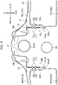
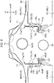
- the second left inner bracket 70L as a protector includes plate portions 71 and 72 that extend in the vehicle front-rear direction and the vehicle height direction, a first mount portion 73 provided in a circumferential edge portion 71a of the plate portion 71 and connected to the vehicle body structural component (more specifically, the tunnel panel 11) of the vehicle 1, and two second mount portions 74 and 74 provided in the circumferential edge portion 71a of the plate portion 71 and connected to the left battery unit 40L.
- the plate portions 71 and 72 include two planar bodies stacked in the vehicle width direction.
- the first plate portion 71 located on the inner side in the vehicle width direction of the two planar bodies is formed in a rectangular shape having a larger dimension in the vehicle front-rear direction than in the vehicle height direction.
- the second plate portion 72 located on the outer side in the vehicle width direction of the two planar bodies is formed in a rectangular shape having substantially the same dimensions as the first plate portion 71.
- the first plate portion 71 and the second plate portion 72 are joined to each other by, for example, welding.
- Each of the two planar bodies constituting the plate portions 71 and 72 is provided with a bead portion that extends in the vehicle front-rear direction.
- the bead portion provided on the first plate portion 71 disposed on the inner side in the vehicle width direction of the two planar bodies forms a first bead portion 71b that projects toward the inner side in the vehicle width direction.
- This first bead portion 71b includes a plurality of bead shapes arranged in the up-down direction.
- the first bead portion 71b has a shape that extends in the vehicle front-rear direction and projects toward the inner side in the vehicle width direction.
- the first bead portion 71b has a concave cross section that is recessed toward the inner side in the vehicle width direction when seen in a cross section orthogonal to the vehicle front-rear direction.
- the bead portion provided in the second plate portion 72 located on the outer side in the vehicle width direction of the two planar bodies forms a second bead portion 72b that projects toward the outer side in the vehicle width direction.
- This second bead portion 72b includes a plurality of bead shapes disposed in the up-down direction. As illustrated in Figs. 5 and 6 , the second bead portion 72b has a shape that extends in the vehicle front-rear direction and projects toward the outer side in the vehicle width direction. In other words, the second bead portion 72b has a concave cross section that is recessed toward the outer side in the vehicle width direction when seen in a cross section orthogonal to the vehicle front-rear direction.
- first bead portions 71b and the second bead portions 72b are disposed so as to face each other. Accordingly, the first bead portion 71b and the second bead portion 72b define a closed cross section that extends in the vehicle front-rear direction when seen in a cross section orthogonal to the vehicle front-rear direction.
- the circumferential edge portion 71a of the first plate portion 71 is bent toward the inner side in the vehicle width direction along the contour of the first plate portion 71.
- the portion (the portion corresponding to the longer side located on the upper end side of the longer side of the rectangle corresponding to the first plate portion 71) located on the upper end side is provided integrally with the first mount portion 73.
- the portion (the portion corresponding to the longer side disposed on the lower end side of the longer side of the rectangle corresponding to the first plate portion 71) located on the lower end side is provided integrally with the second mount portions 74 and 74.
- the first mount portion 73 is formed in a planar shape that extends toward the inner side in the vehicle width direction from the upper end portion of the first plate portion 71.
- the first mounting portion 73 is disposed at the middle position in the vehicle front-rear direction of the first plate portion 71.
- the first mount portion 73 is fastened to the upper tunnel reinforcement 12 with bolts 106. This fastening connects the second left inner bracket 70L to the tunnel panel 11 via the upper tunnel reinforcement 12.
- the dimension in the vehicle front-rear direction of the first mount portion 73 is smaller than the dimension in the vehicle front-rear direction of the first plate portion 71.
- the second mount portions 74 and 74 are formed in planar shapes that extend toward the inner side in the vehicle width direction from the lower end portion of the first plate portion 71.
- the second mount portions 74 and 74 are disposed on the front side in the vehicle front-rear direction of the first plate portion 71 and on the rear side in the vehicle front-rear direction of the first plate portion 71, respectively.
- the second mount portions 74 are fastened to the lower flange 42aL of the second left case 42L with bolts 107. This fastening mounts the second left inner bracket 70L to the left battery unit 40L via the flange 42aL.
- the dimensions in the vehicle front-rear direction of the second mount portions 74 and 74 are smaller than the dimension in the vehicle front-rear direction of the first plate portion 71.
- the first mount portion 73 is connected to the tunnel panel 11 and the second mount portions 74 and 74 are connected to the left battery unit 40L, whereby the left battery unit 40L is supported by the vehicle body via the second left inner bracket 70L.
- a second right inner bracket 70R has both the function as a protector and the function as a mount bracket.
- the second left inner bracket 70L extends upward from the upper surface (the portion to which the second mount portions 74 and 74 are connected) of the lower flange 42aL to the lower surface (the portion to which the first mounting portion 73 is connected) of the upper tunnel reinforcement 12.
- the upper end portion of the first plate portion 71 projects upward of the upper end portion (left upper surface portion 46L) of the left battery unit 40L (see Fig. 6 ) and covers, from the inner side, the side surface portion (particularly, the side surface portion of the left inner side surface portion 45L on the vehicle rear side of the universal joint 9a) defined by the first left case 41L on the upper side.
- the second shaft portion 9c of the rear propeller shaft 9 disposed on the vehicle rear side of the universal joint 9a is disposed above the left battery unit 40L in the vehicle height direction when seen in a cross section that passes through at least the first plate portion 71.
- the height positions of the upper end portion of the first plate portion 71 and the first mount portion 73 are set to a position that is higher than the lower end portion of the second shaft portion 9c and lower than the upper end portion of the second shaft portion 9c in the vehicle height direction.
- the height positions of the first bead portion 71b and the second bead portion 72b are set to the same height position as the side surface portion (particularly, the side surface portion on the vehicle rear side of the universal joint 9a) of the left inner side surface portion 45L defined by the first left case 41L on the upper side.
- the peripheral structure of the right battery unit 40R will be described.
- the detailed shape is different from that of the left battery unit 40L, but the basic structure is symmetrical with respect to that of the left battery unit 40L. Accordingly, only the different portion between the peripheral structure of the right battery unit 40R and the peripheral structure of the left battery unit 40L will be described in detail and the same portion as the peripheral structure of the left battery unit 40L will not be described in detail as appropriate.
- the right battery unit 40R has a box shape and is substantially rectangular in bottom view.
- the right battery unit 40R includes the right front surface portion 43R, a right outer side surface portion 44R that extends in the front-rear direction from the outer end portion in the vehicle width direction of the right front surface portion 43R, a right inner side surface portion 45R that extends in the front-rear direction from the inner end portion in the vehicle width direction of the right front surface portion 43R, a right upper surface portion 46R that spreads horizontally from the upper end portion of the right front surface portion 43R toward the vehicle rear side, a right lower surface portion 47R that spreads from the lower end portion of the right front surface portion 43R so as to face the right upper surface portion 46R in the up-down direction, and a right rear surface portion 48R that faces the right front surface portion 43R in the front-rear direction.
- the right inner side surface portion 45R extends along the inner wall portion (right inner side surface of the tunnel panel 11) of
- the edges of the surface portions 43R to 48R of the right battery unit 40R are integrated with each other.
- the inner portion in the vehicle width direction is located behind the outer portion in the vehicle width direction.
- the right battery unit 40R is configured by fastening the pair of upper and lower case members.
- the right battery unit 40R includes a first right case 41R and a second right case 42R divided in the up-down direction.
- the first right case 41R is a case member including the right upper surface portion 46R and is located relatively on the upper side.
- the second right case 42R is a case member including the right lower surface portion 47R and is located relatively on the lower side.
- first right case 41R and the second right case 42R are formed in box shapes having openings that are open toward the vehicle upper side or the vehicle lower side and have flanges 41aR and 42aR provided along the circumferential edges of the openings, respectively.
- first right case 41R has the flange 41aR that extends along the edge in the lower end portion
- second right case 42R has the flange 42aR that extends along the edge in the upper end portion.
- the first right case 41R and the second right case 42R as case members can be fastened to each other by inserting bolts (fasteners) into the flanges 41aR and 42aR.
- the first right case 41R and the second right case 42R are connected to each other by bolts with the flanges 41aR and 42aR thereof abutting against each other in the up-down direction.
- the right battery unit 40R is connected to the vehicle body structural component via a plurality of mount brackets 51R and 52R.
- the mount brackets 51R and 52R according to the embodiment are mounted to the right outer side surface portion 44R that faces the outer side (right side) in the vehicle width direction of the right battery unit 40R and the right inner side surface portion 45R that faces the inner side (left side) in the vehicle width direction of the right battery unit 40R, respectively.
- the right outer brackets 52R as the mount brackets are mounted to the right outer side surface portion 44R of the right battery unit 40R (see Figs. 1 to 6 ).
- the right outer brackets 52R connect the right battery unit 40R to the floor panel 30.
- the right inner brackets 51R as the mount brackets are mounted to the right inner side surface portion 45R of the right battery unit 40R (see Figs. 1 to 6 ).
- the right inner brackets 51R connect the right battery unit 40R to the tunnel panel 11.
- the plurality of right outer brackets 52R are spaced apart from each other in the vehicle front-rear direction.
- the right outer bracket 52R according to the embodiment includes at least a first right outer bracket 80R that extends in the vehicle front-rear direction.
- the right outer bracket 52R includes the first right outer bracket 80R described above and a second right outer bracket 90R disposed behind the first right outer bracket 80R in the vehicle front-rear direction. Since the first and second right outer brackets 80R and 90R have structures that are substantially reversed horizontally from those of the first and second left outer brackets 80L and 90L, the details thereof will not be described.
- the plurality of right inner brackets 51R are spaced apart from each other in the vehicle front-rear direction.
- the right inner bracket 51R according to the embodiment includes a first right inner bracket 60R and the second right inner bracket 70R that is disposed side-by-side with the first right inner bracket 60R in the vehicle front-rear direction and is located behind the first right inner bracket 60R.
- the first right inner bracket 60R is disposed as a protector that covers the right inner side surface portion 45R from the inner side in the vehicle width direction.
- the first right inner bracket 60R is the member that prevents the transfer 4a from coming into contact with the right inner side surface portion 45R of the right battery unit 40R when the transmission 4 enters the floor tunnel 10 together with the transfer 4a at the time of a front collision.
- the right inner protector 70R is made of, for example, cast iron.
- the second right inner bracket 70R is disposed so as to face the second left inner bracket 70L in the vehicle width direction.
- the second right inner bracket 70R is disposed on the vehicle rear side of the universal joint 9a as in the second left inner bracket 70L.
- the second right inner bracket 70R is configured as a planar protector that covers the portion of the right inner side surface portion 45R located on the vehicle rear side of the universal joint 9a.
- the second right inner bracket 70R functions if the rear propeller shaft 9 bends in the left-right direction starting from the universal joint 9a when the transmission 4 enters the floor tunnel 10 together with the transfer 4a at the time of a front collision.
- the second right inner bracket 70R exerts the function as a member for suppressing the contact between the universal joint 9a and the right inner side surface portion 45R of the right battery unit 40R.
- the right inner protector 70R is made from, for example, a high-tensile steel plate component.
- the dimension in the vehicle front-rear direction of the second right inner bracket 70R is larger than the dimension in the vehicle front-rear direction of the universal joint 9a.
- the dimension in the vehicle height direction of the second right inner bracket 70R is larger than the length of the side surface portion defined by the first left case 41R on the upper side of the right inner side surface portion 45R.
- the second right inner bracket 70R as a protector includes the plate portions 71 and 72 that extend in the vehicle front-rear direction and the vehicle height direction, the first mount portion 73 provided in the circumferential edge portion 71a of the plate portion 71 and connected to the vehicle body structural component (more specifically, the tunnel panel 11) of the vehicle 1, and the two second mount portions 74 and 74 provided in the circumferential edge portion 71a of the plate portion 71 and connected to the right battery unit 40R (see Figs. 5 and 6 ).
- the details of the portions are the same as in the plate portions 71 and 72, the first mount portion 73, and the second mount portions 74 and 74 of the second left inner bracket 70L. These components have structures in which the portions of the second left inner bracket 70L are substantially reversed horizontally.
- the plate portions 71 and 72 include two planar bodies stacked in the vehicle width direction.
- the first plate portion 71 located on the inner side in the vehicle width direction of the two planar bodies is formed in a rectangular shape having a larger dimension in the vehicle front-rear direction than in the vehicle height direction.
- the second plate portion 72 located on the outer side in the vehicle width direction of the two planar bodies is formed in a rectangular shape having substantially the same dimensions as the first plate portion 71.
- Each of the two planar bodies constituting the plate portions 71 and 72 is provided with a bead portion that extends in the vehicle front-rear direction.
- the bead portion provided on the first plate portion 71 located on the inner side in the vehicle width direction of the two planar bodies forms the first bead portion 71b that projects toward the inner side in the vehicle width direction.
- the bead portion provided in the second plate portion 72 located on the outer side in the vehicle width direction of the two planar bodies forms the second bead portion 72b that projects toward the outer side in the vehicle width direction.
- first bead portions 71b and the second bead portions 72b are disposed so as to face each other. Accordingly, the first bead portion 71b and the second bead portion 72b define a closed cross section that extends in the vehicle front-rear direction when seen in a cross section orthogonal to the vehicle front-rear direction.
- the circumferential edge portion 71a of the first plate portion 71 is bent toward the inner side in the vehicle width direction along the contour of the first plate portion 71.
- the circumferential edge portion 71a is provided integrally with the first mount portion 73 and the second mount portions 74 and 74.
- the first mount portion 73 is fastened to the upper tunnel reinforcement 12 with the bolts 106. This fastening connects the second left inner bracket 70L to the tunnel panel 11 via the upper tunnel reinforcement 12.
- the second mount portions 74 and 74 are fastened to the lower flange 42aL of the second left case 42L with the bolt 107. This fastening mounts the second left inner bracket 70L to the left battery unit 40L via the flange 42aL.
- the first mount portion 73 is connected to the tunnel panel 11 and the second mount portions 74 and 74 are connected to the right battery unit 40R, whereby the right battery unit 40R is supported by the vehicle body via the second right inner bracket 70R.
- the second right inner bracket 70R has both the function as a protector and the function as a mount bracket.
- the second right inner bracket 70R extends upward from the upper surface (the portion to which the second mount portions 74 and 74 are connected) of the lower flange 42aR to the lower surface (the portion to which the first mount portion 73 is connected) of the upper tunnel reinforcement 12.
- the upper end portion of the first plate portion 71 projects upward of the upper end portion (right upper surface portion 46R) of the right battery unit 40R (see Fig. 6 ) and covers, from the inner side, the side surface portion (particularly, the side surface portion on the vehicle rear side of the universal joint 9a) defined by the first right case 41R on the upper side of the right inner side surface portion 45R.
- the height positions of the first bead portion 71b and the second bead portion 72b are set to be the same as the height position of the side surface portion (particularly, the side surface portion on the vehicle rear side of the universal joint 9a) defined by the first right case 41R on the upper side of the right inner side surface portion 45R.
- the rear propeller shaft 9 bends starting from the universal joint 9a, whereby the transmission 4 moves backward smoothly.
- the universal joint 9a with which the bending starts may be displaced to the left and right while moving backward.
- the contact between the universal joint 9a and the left and right battery units 40L and 40R can be suppressed by covering the portion disposed on the vehicle rear side of the universal joint 9a with the second left inner bracket 70L and the second right inner bracket 70R as protectors as illustrated in Fig. 4 .
- This can satisfactorily protect the left and right battery units 40L and 40R without interfering with the backward movement of the transmission 4.
- the left and right battery units 40L and 40R are protected more reliably by setting the dimension of the first plate portion 71 to be relatively larger than other components as illustrated in Figs. 7 and 8 .
- the weights of the second left inner bracket 70L and the second right inner bracket 70R as protectors can be reduced advantageously by setting the dimensions of the first and second mount portions 73 and 74 to be relatively smaller. This can reduce the weights of the second left inner bracket 70L and the second right inner bracket 70R as much as possible while ensuring the protection performance for the battery units 40L and 40R.
- the bending of the first plate portion 71 about the central axis that extends in the vehicle height direction can be suppressed advantageously by providing the first bead portion 71b that extends in the vehicle front-rear direction in the first plate portion 71.
- the first bead portion 71b and the second bead portion 72b define a closed cross section when seen in a cross section orthogonal to the vehicle front-rear direction.
- the distortion of the first plate portion 71 can be suppressed by bending the circumferential edge portion 71a of the first plate portion 71 as illustrated in Figs. 7 and 8 .
- the deformation of the first and second mount portions 73 and 74 can be suppressed advantageously by forming the first and second mount portions 73 and 74 on the circumferential edge portion 71a bent as described above.
- the second left inner bracket 70L and the second right inner bracket 70R as protectors extend upward from the flanges 42aL and 42aR of the second left case 42L and the second right case 42R, respectively.
- the flanges 42aL and 42aR can be used as the mount positions of the second left inner bracket 70L and the second right inner bracket 70R while the second left inner bracket 70L and the second right inner bracket 70R protect the left and right battery units 40L and 40R. This can lay out the second left inner bracket 70L and the second right inner bracket 70R more appropriately while ensuring the protection performance for the battery units 40L and 40R.
- protectors that are easier to mold can be used by configuring the protectors so as to extend from the flanges 42aL and 42aR. This contributes to the improvement of the moldability of the second left inner bracket 70L and the second right inner bracket 70R as protectors.
- the vehicle 1 is a four-wheel-drive vehicle in the embodiment described above.
- the vehicle 1 is not limited to a four-wheel-drive vehicle and may be, for example, an FR vehicle.
- the transfer 4a and the front propeller shaft 8 are omitted.
- the vehicle 1 may be an electric vehicle that does not have the engine 2 but has only the motor 3 as the drive source.
Landscapes
- Engineering & Computer Science (AREA)
- Chemical & Material Sciences (AREA)
- Transportation (AREA)
- Mechanical Engineering (AREA)
- Combustion & Propulsion (AREA)
- Life Sciences & Earth Sciences (AREA)
- Electrochemistry (AREA)
- General Chemical & Material Sciences (AREA)
- Chemical Kinetics & Catalysis (AREA)
- Sustainable Development (AREA)
- Sustainable Energy (AREA)
- Power Engineering (AREA)
- Aviation & Aerospace Engineering (AREA)
- Body Structure For Vehicles (AREA)
- Arrangement Or Mounting Of Propulsion Units For Vehicles (AREA)
- Hybrid Electric Vehicles (AREA)
- Battery Mounting, Suspending (AREA)
- Motor Power Transmission Devices (AREA)
Abstract
Description
- The present disclosure relates to a lower structure of a vehicle.
- Patent document 1 discloses an example of the lower structure of a vehicle. Specifically, patent document 1 discloses a vehicle including a propeller shaft that extends from the rear end portion of a transmission toward the vehicle rear and transmits power to the rear wheels, and battery packs disposed below the floor panels on the left and right sides of a floor tunnel.
- According to patent document 1, the left and right battery packs are spaced apart in the vehicle width direction. In addition, the propeller shaft is laid out so as to be disposed between the left and right battery packs in the vehicle width direction, more accurately between the inner side surface portions of the battery packs.
- [Patent document 1]
JP-A-2013-67334 - By the way, the propeller shaft configured as described above may include two shaft portions connected to each other via a joint portion including a so-called universal joint or the like.
- In this case, for example, when a gearbox moves backward at the time of a front collision of the vehicle, the propeller shaft is bent starting from the joint portion, whereby the gearbox can move backward more smoothly without suffering interference. The backward movement of the gearbox is effective in ensuring the crash stroke of the vehicle body.
- However, when the propeller shaft is laid out between the left and right battery packs (referred to below as the "battery units") as described in patent document 1, since the joint portion with which the bending starts is displaced to the left and right while moving backward, this joint portion may come into contact with the battery units. Such contact is inconvenient because there is concern about damage to the battery units.
- The present disclosure addresses the problem described above with an object of satisfactorily protecting the left and right battery units without interfering with the backward movement of the gearbox.
- A first aspect of the present disclosure relates to a lower structure of a vehicle in which a rear wheel serves as a drive wheel. The vehicle includes a gearbox disposed with at least a portion thereof present in a floor tunnel, the portion being present on a vehicle rear side of the gearbox; a propeller shaft that extends from the gearbox toward the vehicle rear side, the propeller shaft transmitting power to the rear wheel; and left and right battery units disposed on a vehicle lower side of left and right floor panels, the left and right floor panels being disposed on a vehicle left side and a vehicle right side of the floor tunnel, in which the propeller shaft has a first shaft portion and a second shaft portion that are arranged in sequence from a vehicle front side, the first shaft portion being connected to the gear box, the second shaft portion being connected to the first shaft portion via a joint portion, each of the left and right battery units has an inner side surface portion that extends along an inner wall portion of the floor tunnel and faces an inner side in a vehicle width direction, and a planar protector that covers a portion of the inner side surface portion is mounted to each of the left and right battery units, the portion being located on the vehicle rear side of the joint portion.
- According to the first aspect, when the gearbox moves backward at the time of a front collision of the vehicle, the propeller shaft bends starting from the joint portion, whereby the gearbox can move backward smoothly. In this case, the joint portion with which the bending starts may be disadvantageously displaced to the left and right while moving backward.
- As a measure against this, according to the first aspect, the contact between the joint portion and the battery units can be suppressed by covering the portion located on the vehicle rear side of the joint portion with the protector. This can satisfactorily protect the left and right battery units without interfering with the backward movement of the gearbox.
- In addition, according to a second aspect of the present disclosure, the protector may include a plate portion that extends in a vehicle front-rear direction and a vehicle height direction, a first mount portion that is provided in a circumferential edge portion of the plate portion and connected to a vehicle body structural component of the vehicle, and a second mount portion that is provided in the circumferential edge portion of the plate portion and connected to one of the left and right battery units, and dimensions in the vehicle front-rear direction of the first mount portion and the second mount portion may be smaller than a dimension in the vehicle front-rear direction of the plate portion.
- According to the second aspect described above, the left and right battery units can be protected more reliably by setting the dimension of the plate portion of the protector that suppresses contact with the battery units to be relatively larger. In contrast, the weight of the protectors can be reduced advantageously by setting the dimensions of the first mount portion and the second mount portion to be relatively smaller. This can reduce the weight of the protectors as much as possible while ensuring the protection performance for the battery units.
- According to a preferred aspect the first mount portion may be connected to a tunnel panel of the vehicle. The tunnel panel forms the floor tunnel, in particular the upper end portion of the tunnel panel may be inclined to the lower side from the front side toward the rear side. Accordingly, the
floor tunnel 10 is narrower in the up-down direction toward the rear side. On the tunnel panel at least of reinforcement may be provided for reinforcement of the tunnel. The first mount portion may then be connected to an upper tunnel reinforcement. - The first mount portion may be disposed at a middle position in the vehicle front-rear direction of the plate portion or at least close to the middle portion of the plate portion.
- In addition, according to a third aspect of the present disclosure, the plate portion may be provided with a bead portion that extends in the vehicle front-rear direction.
- According to the third aspect described above, the bending of the plate portion about the central axis that extends in the vehicle height direction can be suppressed advantageously by providing the bead portion that extends in the vehicle front-rear direction in the plate portion.
- In addition, according to a fourth aspect of the present disclosure, the protector may include a further second plate portion, the plate portions (71, 72)may include two planar bodies stacked in the vehicle width direction, the bead portion may be provided on each of the two planar bodies, the bead portion on one planar body of the two planar bodies may be a first bead portion that projects toward the inner side in the vehicle width direction, the one planar body being located on an inner side in the vehicle width direction, the bead portion on one planar body of the two planar bodies may be a second bead portion that projects toward the outer side in the vehicle width direction, the one planar body being located on an outer side in the vehicle width direction, and the first bead portion and the second bead portion may be disposed so as to face each other.
- According to the fourth aspect described above, the first bead portion and the second bead portion define a closed cross section when seen in a cross section orthogonal to the vehicle front-rear direction. With this structure, bending of the plate portion about the central axis that extends in the vehicle height direction can be further suppressed advantageously.
- The plate portion may be formed of a rectangular shape having a larger dimension in the vehicle front-rear direction than in the vehicle height direction and the second plate portion is preferably formed in a rectangular shape having substantially the same dimensions as the first plate portion.
- According to a further preferred aspect the bead portion may include a plurality of bead shapes disposed in the up-down direction.
- In addition, according to a fifth aspect of the present disclosure, the circumferential edge portion of the plate portion may be bent toward the inner side in the vehicle width direction, and the first mount portion and the second mount portion may be formed integrally with the bent circumferential edge portion of the plate portion.
- According to the fifth aspect described above, the distortion of the plate portion can be suppressed by bending the circumferential edge portion of the plate portion. In addition, the deformation of the first and the second mount portions can be suppressed advantageously by forming the first mount portion and the second mount portion in the portion bent in this way.
- In addition, according to a sixth aspect of the present disclosure, the propeller shaft may be disposed above the left and right battery units in the vehicle height direction when seen in a cross section passing through at least the protector, each of the left and right battery units may be configured by fastening a pair of upper and lower case members, the case members may be formed in box shapes having openings that are open toward a vehicle upper side or the vehicle lower side and have a flanges provided along circumferential edges of the openings, the case members may be fastened to each other by inserting fasteners into the flanges, and the protector may extend upward from each of the flanges.
- According to the sixth aspect described above, the protector is configured to extend upward from the flange for connecting the case members to each other. With this structure, the flange can be used as the mounting position of the protector while the battery units are protected by the protector. This can lay out the protector more appropriately while ensuring the protection performance for the battery units. In addition, a protector that is easier to mold can be used by configuring the protector so as to extend from the flange. This contributes to the improvement of the moldability of the protector.
- According to a further aspect the planar protector can be made of a high tensile steel plate.
- According to a further aspect the dimension of the planar protector in the vehicle front-rear direction is larger than the dimension of the universal joint in the vehicle front-rear direction. Additionally or alternatively, the dimension of the planar protector in the vehicle height direction is larger than the height of the upper case member. The preferred dimension of the protector protects a sufficient area of the battery unit that can be hit by the joint portion of the shaft.
- According to a preferred aspect, the planar protector protects the battery unit from being hit by the shaft or joint portion of the shaft during a collision. In addition, the protector serves as a bracket for mounting the battery unit to the vehicle structure.
- As described above, according to the present disclosure, the left and right battery units can be satisfactorily protected without interfering with the backward movement of the gearbox.
-
- [
Fig. 1] Fig. 1 is a schematic diagram illustrating a driving system of a vehicle to which a lower structure of a vehicle according to the present disclosure has been applied. - [
Fig. 2] Fig. 2 is a bottom view illustrating the structure of a vehicle front side as seen from below. - [
Fig. 3] Fig. 3 is a diagram illustrating the structure inside a floor tunnel as seen from a vehicle right side. - [
Fig. 4] Fig. 4 is a perspective view illustrating the peripheral structure of battery units as seen from diagonally above. - [
Fig. 5] Fig. 5 is a sectional view illustrating a cross section taken along line I-I inFig. 3 . - [
Fig. 6] Fig. 6 is a sectional view illustrating a cross section taken along line II-II inFig. 3 . - [
Fig. 7] Fig. 7 is a perspective view illustrating a second left inner bracket as seen from an outer side in a vehicle width direction. - [
Fig. 8] Fig. 8 is a perspective view illustrating the second left inner bracket as seen from an inner side in the vehicle width direction. - An embodiment of the present disclosure will be described below with reference to the drawings. It should be noted that the following description is an example.
-
Fig. 1 is a schematic diagram illustrating a driving system of a vehicle 1 to which a lower structure of a vehicle according to the present disclosure has been applied. In addition,Fig. 2 is a bottom view illustrating the structure of a front side portion of the vehicle 1 as seen from below. - It should be noted that the terms "front", "rear", "upper", and "lower" in the following description are defined with reference to the vehicle 1. That is, in the following description, "front" refers to the front side in the vehicle front-rear direction and "rear" refers to the rear side in the vehicle front-rear direction. Similarly, "upper" refers to the upper side in the vehicle height direction and "lower" refers to the lower side in the vehicle height direction. In the following description, the vehicle front-rear direction may be simply referred to as the "front-rear direction", the vehicle height direction may be simply referred to as the "up-down direction", and the vehicle width direction may be simply referred to as the "left-right direction".
- In addition, the terms "left" and "right" in the following description are also defined with reference to the vehicle 1. That is, in the following description, "left" refers to the left side in the vehicle width direction when the vehicle 1 is seen from the rear side to the front side, and "right" refers to the right side when the vehicle 1 is seen from the rear side to the front side.
- The vehicle 1 illustrated in
Fig. 1 is a hybrid vehicle. Specifically, as illustrated inFig. 1 , the vehicle 1 includes anengine 2 and amotor 3 as drive sources (power trains) and atransmission 4 that changes the speed of a driving force transmitted from at least one of theengine 2 and themotor 3 and transmits the driving force. Theengine 2 is housed in an engine room disposed in front of a vehicle interior. Theengine 2 is vertically mounted at a substantially middle position in the vehicle width direction in the engine room. Themotor 3 is disposed behind theengine 2 via adamper 5. Thetransmission 4 is vertically mounted behind themotor 3. - The vehicle 1 has at least left and right
rear wheels 7 as driving wheels. More specifically, the vehicle 1 is configured as a four-wheel-drive vehicle that has left and rightfront wheels 6 and the left and rightrear wheels 7 as driving wheels. The rear portion of thetransmission 4 is atransfer 4a that transmits the driving force to thefront wheels 6 and therear wheels 7. Afront propeller shaft 8 extends toward the front side from thetransfer 4a. Arear propeller shaft 9 extends toward the rear side from thetransfer 4a. Thefront propeller shaft 8 is disposed slightly to the right of the middle in the vehicle width direction. Therear propeller shaft 9 is disposed substantially in the middle in the vehicle width direction. Although not described in detail, the driving force changed in speed by thetransmission 4 is transmitted to thefront propeller shaft 8 and therear propeller shaft 9 via thetransfer 4a. Thefront propeller shaft 8 transmits the driving force to thefront wheels 6 and therear propeller shaft 9 transmits the driving force to therear wheels 7. Therear propeller shaft 9 is an example of the "propeller shaft" in the embodiment. - As illustrated in
Fig. 2 , thetransmission 4 is disposed with at least the portion thereof on the vehicle rear side present in afloor tunnel 10. More specifically, thetransmission 4 is disposed so as to be inclined to the lower side from the front side toward the rear side. - The
floor tunnel 10 is formed by atunnel panel 11. As illustrated inFig. 3 , the upper end portion of thetunnel panel 11 is inclined to the lower side from the front side toward the rear side. Accordingly, thefloor tunnel 10 is narrower in the up-down direction toward the rear side. - The
rear propeller shaft 9 is disposed in thefloor tunnel 10. Therear propeller shaft 9 is connected to thetransfer 4a via arubber cup 4b. Therear propeller shaft 9 extends from the position of therubber cup 4b toward the rear side while being inclined to the lower side. A universal joint 9a is provided at the middle position in the front-rear direction of therear propeller shaft 9. Therear propeller shaft 9 bends in the up-down direction and the left-right direction starting from the universal joint 9a at the time of, for example, a front collision. The universal joint 9a is an example of the "joint portion" in the embodiment. - The
rear propeller shaft 9 according to the embodiment is divided into two portions in the front-rear direction by the universal joint 9a. Specifically, therear propeller shaft 9 has afirst shaft portion 9b connected to thetransmission 4 and asecond shaft portion 9c connected to thefirst shaft portion 9b via the universal joint 9a that are arranged in sequence from the vehicle front side. - Another rubber cup is provided in front of the universal joint 9a of the
rear propeller shaft 9. Asupport bracket 9d that supports therear propeller shaft 9 is provided at the position of this rubber cup. Thesupport bracket 9d has a U-shape that covers the rubber cup from below and the left and right end portions thereof are connected to anupper tunnel reinforcement 12 for reinforcement provided on thetunnel panel 11 with bolts. -
Side tunnel reinforcements 13 that extend in the front-rear direction are provided in the left and right end portions of thetunnel panel 11, respectively. Theside tunnel reinforcements 13 are members for reinforcing thetunnel panel 11. Theside tunnel reinforcements 13 are connected to the inner portion of thetunnel panel 11 by welding so as to form closed cross sections between theside tunnel reinforcements 13 and thetunnel panel 11. - A pair of left and
right floor panels 30 constituting the floor of the vehicle interior are disposed on the vehicle left side and the vehicle right side of thetunnel panel 11, respectively. Thefloor panels 30 extend horizontally in the front-rear direction and the left-right direction. As illustrated inFig. 5 , the right end portion of theleft floor panel 30 is connected to the left end portion of thetunnel panel 11 by welding. Although not illustrated, the left end portion of theright floor panel 30 is connected to the right end portion of thetunnel panel 11 by welding. The left andright floor panels 30 are connected to each other in the left-right direction by thetunnel panel 11. The connection portions between thefloor panels 30 and thetunnel panel 11 are located at the same positions as the connection portions between thetunnel panel 11 and theside tunnel reinforcements 13 or located on the outer side in the vehicle width direction of the connection portions between thetunnel panel 11 and theside tunnel reinforcements 13. - As illustrated in
Fig. 2 , left andright toe boards 32 are connected to the front end portions of the left andright floor panels 30 by welding, respectively. The left andright toe boards 32 extend from the front end portions of the left andright floor panels 30 toward the front side while being inclined upward. The upper end portions of the left andright toe boards 32 are joined to the lower end portion of a dash panel (not illustrated) that separates the vehicle interior from the engine room. The right end portion of theleft toe board 32 is connected to the left end portion of thetunnel panel 11 by welding. The left end portion of theright toe board 32 is connected to the right end portion of thetunnel panel 11 by welding. - As illustrated in
Fig. 2 , a pair of left and right floor frames 21 that extend in the front-rear direction are connected to the lower surfaces of the left andright floor panels 30 and the lower surfaces of the left andright toe boards 32, respectively. The left and right floor frames 21 extend toward the rear side while being inclined to the outer side in the vehicle width direction so as to be separated from each other in the vehicle width direction, and then extend straight toward the rear side in parallel to each other. - As illustrated in
Fig. 2 , a pair of left andright side sills 22 that extend in the front-rear direction are connected to the outer end portions in the vehicle width direction of the left andright floor panels 30. The left andright side sills 22 are located on the outer side in the vehicle width direction of the left and right floor frames 21. Although not illustrated, theleft side sill 22 is connected to the left end portion of theleft floor panel 30 by welding. Theright side sill 22 is connected to the right end portion of theright floor panel 30 by welding. - As illustrated in
Fig. 2 , the front end portions of the left and right floor frames 21 are connected to the front end portions of the left andright side sills 22 via left andright gussets 23, respectively. - As illustrated in
Figs. 1 and2 , on the left and right sides of thefloor tunnel 10 in the area behind thetransfer 4a, left andright battery units motor 3 is stored are disposed. In particular, thebattery units floor panels 30 disposed on the vehicle left side of and the vehicle right side of thefloor tunnel 10. - The
left battery unit 40L is disposed below the passenger seat and theright battery unit 40R is disposed below the driver seat. The left andright battery units left battery unit 40L and the left end portion of theright battery unit 40R slightly overlap thefloor tunnel 10 when seen from above or below in the up-down direction. - Both the left and
right battery units right battery units right battery units - As illustrated in
Fig. 2 , atransmission support member 33 that supports thetransfer 4a (that is, the transmission 4) is provided slightly in front of the left andright battery units transmission support member 33 is disposed so as to face a leftfront surface portion 43L and a rightfront surface portion 43R of the left andright battery units - As illustrated in
Fig. 2 , anexhaust pipe 28 through which the exhaust gas from theengine 2 passes is disposed on the right side of thetransmission support member 33. Theexhaust pipe 28 extends from theengine 2 toward thefloor tunnel 10 through the right side of thetransmission 4 and thetransmission support member 33, passes through thefloor tunnel 10, and extends toward the rear side. Theexhaust pipe 28 has an exhaustgas purification device 29 on the right side of thetransmission support member 33. The exhaustgas purification device 29 has a horizontally long elliptical shape and has an exhaust gas purification catalyst 29a therein. Theexhaust pipe 28 enters thefloor tunnel 10 through the space between thefront surface portion 43R of theright battery unit 40R and thetransmission support member 33 at the same height as thefront surface portion 43R of theright battery unit 40R and thetransmission support member 33. - Next, the peripheral structures of the
left battery unit 40L and theright battery unit 40R will be described in detail. - First, the peripheral structure of the
left battery unit 40L will be described. As illustrated inFigs. 2 and4 , theleft battery unit 40L has a box shape and is substantially rectangular in bottom view. - Specifically, the
left battery unit 40L includes the leftfront surface portion 43L, a left outerside surface portion 44L that extends in the front-rear direction from the outer end portion in the vehicle width direction of the leftfront surface portion 43L, a left innerside surface portion 45L that extends in the front-rear direction from the inner end portion in the vehicle width direction of the leftfront surface portion 43L, a leftupper surface portion 46L that spreads horizontally from the upper end portion of the leftfront surface portion 43L toward the vehicle rear side, a leftlower surface portion 47L that spreads from the lower end portion of the leftfront surface portion 43L so as to face the leftupper surface portion 46L in the up-down direction, and a leftrear surface portion 48L that faces the leftfront surface portion 43L in the front-rear direction. Of these, the left innerside surface portion 45L extends along the inner wall portion (the left inner side surface of the tunnel panel 11) of thefloor tunnel 10 and faces the inner side (right side) in the vehicle width direction. - The edges of the
surface portions 43L to 48L of theleft battery unit 40L are integrated with each other. The inner portion in the vehicle width direction of the leftfront surface portion 43L is located behind the outer portion in the vehicle width direction. This forms a space in which thetransmission support member 33 is disposed while theleft battery unit 40L is made as large as possible. - In addition, the
left battery unit 40L according to the embodiment is configured by fastening a pair of upper and lower case members. Specifically, as illustrated inFigs. 5 and6 , theleft battery unit 40L has a firstleft case 41L and a secondleft case 42L divided in the up-down direction. The firstleft case 41L is a case member including the leftupper surface portion 46L and is located relatively upward. The secondleft case 42L is a case member including the leftlower surface portion 47L and is located relatively downward. - The first
left case 41L and the secondleft case 42L are formed in box shapes having openings that are open toward the vehicle upper side or the vehicle lower side and have flanges 41aL and 42aL provided along the circumferential edges of the openings. Specifically, the firstleft case 41L has the flange 41aL that extends along the edge in the lower end portion thereof and the secondleft case 42L has the flange 42aL that extends along the edge in the upper end portion thereof. - The first
left case 41L and the secondleft case 42L as case members can be fastened to each other by inserting a bolt (fastener) into the flanges 41aL and 42aL. Specifically, the firstleft case 41L and the secondleft case 42L are connected to each other by the bolt with the flanges 41aL and 42aL thereof abutting against each other in the up-down direction. A sealing member is disposed in the contact portion between the firstleft case 41L and the secondleft case 42L. - The
left battery unit 40L is connected to the vehicle structural component via a plurality ofmount brackets mount brackets side surface portion 44L that faces the outer side (left side) in the vehicle width direction of theleft battery unit 40L and the left innerside surface portion 45L that faces the inner side (right side) in the vehicle width direction of theleft battery unit 40L, respectively. - Specifically, the left
outer bracket 52L as a mount bracket is mounted to the left outerside surface portion 44L of theleft battery unit 40L (seeFigs. 1 to 6 ). This leftouter bracket 52L connects theleft battery unit 40L to thefloor panel 30. Similarly, the leftinner bracket 51L as a mount bracket is mounted to the left innerside surface portion 45L of theleft battery unit 40L (seeFigs. 1 to 6 ). This leftinner bracket 51L connects theleft battery unit 40L to thetunnel panel 11. - The plurality of left
outer brackets 52L are spaced apart from each other in the vehicle front-rear direction. Here, the leftouter bracket 52L according to the embodiment includes at least a first leftouter bracket 80L that extends in the vehicle front-rear direction. - Specifically, the left
outer bracket 52L according to the embodiment includes the first leftouter bracket 80L described above and a second leftouter bracket 90L disposed behind the first leftouter bracket 80L in the vehicle front-rear direction. - Of these, the first left
outer bracket 80L extends in the vehicle front-rear direction so as to pass through the position of the center of gravity of theleft battery unit 40L in the vehicle front-rear direction. Specifically, the front end portion of the first leftouter bracket 80L is disposed on the vehicle front side of the position of the center of gravity of theleft battery unit 40L, and the rear end portion of the first leftouter bracket 80L is disposed on the vehicle rear side of the center of gravity of theleft battery unit 40L. In the example illustrated inFig. 2 , the first leftouter bracket 80L is mounted to the middle position in the front-rear direction of the left outerside surface portion 44L. - Although not illustrated, the lower portion of the first left
outer bracket 80L is mounted to the secondleft case 42L with bolts. The upper end portion of the first leftouter bracket 51L is fixed to the lower surface of theleft floor frame 21 with bolts. - In contrast, the second left
outer bracket 90L is mounted to the position of the rear end of the left outerside surface portion 44L. Although not illustrated, the lower portion of the second leftouter bracket 90L is mounted to the secondleft case 42L with bolts. The upper end portion of the second leftouter bracket 90L is fixed to the lower surface of theleft floor frame 21 with bolts. - The plurality of left
inner brackets 51L are spaced apart from each other in the vehicle front-rear direction. Here, the leftinner bracket 51L according to the embodiment includes a first leftinner bracket 60L and a second leftinner bracket 70L that is disposed side-by-side with the first leftinner bracket 60L in the vehicle front-rear direction and is located on the vehicle rear side of the first leftinner bracket 60L. - Of these, the first left
inner bracket 60L is disposed on the vehicle front side of the universal joint 9a and is disposed closer to thetransmission 4 than the second leftinner bracket 70L. More specifically, the first leftinner bracket 60L is disposed closer to the position of the center of gravity of theleft battery unit 40L in the vehicle front-rear direction than the second leftinner bracket 70L. This makes the first leftinner bracket 60L closer to the first leftouter bracket 80L in the vehicle front-rear direction than the second leftouter bracket 90L. In the example illustrated inFig. 2 , the first leftinner bracket 60L is configured to cover the front side portion of the left innerside surface portion 45L from the inner side in the vehicle width direction. - The first left
inner bracket 60L serves as a mount bracket for connecting theleft battery unit 40L to the vehicle body structural component and also serves as a protector that covers the left innerside surface portion 45L from the inner side in the vehicle width direction. The first leftinner bracket 60L is the member that prevents thetransfer 4a from coming into contact with the left innerside surface portion 45L of theleft battery unit 40L when thetransmission 4 enters thefloor tunnel 10 together with thetransfer 4a at the time of a front collision. The second leftinner protector 70L is made of, for example, cast iron. - The second left
inner bracket 70L is disposed on the vehicle rear side of the universal joint 9a. In addition, as illustrated inFig. 3 , the second leftinner bracket 70L is closer to the universal joint 9a than the first leftinner bracket 60L in the vehicle front-rear direction. As illustrated inFig. 2 , the first leftinner bracket 60L is disposed at the middle position between the first leftouter bracket 80L and the second leftouter bracket 90L in the vehicle front-rear direction. - The second left
inner bracket 70L is configured as a planar protector that covers the portion of the left innerside surface portion 45L located on the vehicle rear side of the universal joint 9a. The second leftinner bracket 70L functions if therear propeller shaft 9 bends in the left-right direction starting from the universal joint 9a when thetransmission 4 enters thefloor tunnel 10 together with thetransfer 4a at the time of a front collision. In this case, the second leftinner bracket 70L exerts the function as a member for suppressing the contact between the universal joint 9a and the left innerside surface portion 45L of theleft battery unit 40L. The second leftinner protector 70L is made from, for example, a high-tensile steel plate component. - As illustrated in
Figs. 3 and4 , the dimension in the vehicle front-rear direction of the second leftinner bracket 70L is larger than the dimension in the vehicle front-rear direction of the universal joint 9a. In addition, as illustrated inFig. 6 , the dimension in the vehicle height direction of the second leftinner bracket 70L is larger than the length of the side surface portion of the left innerside surface portion 45L defined by the firstleft case 41L on the upper side. - Specifically, as illustrated in
Figs. 5 to 8 , the second leftinner bracket 70L as a protector includesplate portions first mount portion 73 provided in acircumferential edge portion 71a of theplate portion 71 and connected to the vehicle body structural component (more specifically, the tunnel panel 11) of the vehicle 1, and twosecond mount portions circumferential edge portion 71a of theplate portion 71 and connected to theleft battery unit 40L. - The
plate portions first plate portion 71 located on the inner side in the vehicle width direction of the two planar bodies is formed in a rectangular shape having a larger dimension in the vehicle front-rear direction than in the vehicle height direction. Thesecond plate portion 72 located on the outer side in the vehicle width direction of the two planar bodies is formed in a rectangular shape having substantially the same dimensions as thefirst plate portion 71. Thefirst plate portion 71 and thesecond plate portion 72 are joined to each other by, for example, welding. - Each of the two planar bodies constituting the
plate portions first plate portion 71 disposed on the inner side in the vehicle width direction of the two planar bodies forms afirst bead portion 71b that projects toward the inner side in the vehicle width direction. Thisfirst bead portion 71b includes a plurality of bead shapes arranged in the up-down direction. As illustrated inFigs. 5 and6 , thefirst bead portion 71b has a shape that extends in the vehicle front-rear direction and projects toward the inner side in the vehicle width direction. In other words, thefirst bead portion 71b has a concave cross section that is recessed toward the inner side in the vehicle width direction when seen in a cross section orthogonal to the vehicle front-rear direction. - In contrast, the bead portion provided in the
second plate portion 72 located on the outer side in the vehicle width direction of the two planar bodies forms asecond bead portion 72b that projects toward the outer side in the vehicle width direction. Thissecond bead portion 72b includes a plurality of bead shapes disposed in the up-down direction. As illustrated inFigs. 5 and6 , thesecond bead portion 72b has a shape that extends in the vehicle front-rear direction and projects toward the outer side in the vehicle width direction. In other words, thesecond bead portion 72b has a concave cross section that is recessed toward the outer side in the vehicle width direction when seen in a cross section orthogonal to the vehicle front-rear direction. - As illustrated in
Figs. 5 and6 , thefirst bead portions 71b and thesecond bead portions 72b are disposed so as to face each other. Accordingly, thefirst bead portion 71b and thesecond bead portion 72b define a closed cross section that extends in the vehicle front-rear direction when seen in a cross section orthogonal to the vehicle front-rear direction. - In addition, the
circumferential edge portion 71a of thefirst plate portion 71 is bent toward the inner side in the vehicle width direction along the contour of thefirst plate portion 71. Of thecircumferential edge portion 71a of thefirst plate portion 71, the portion (the portion corresponding to the longer side located on the upper end side of the longer side of the rectangle corresponding to the first plate portion 71) located on the upper end side is provided integrally with thefirst mount portion 73. Of thecircumferential edge portion 71a of thefirst plate portion 71, the portion (the portion corresponding to the longer side disposed on the lower end side of the longer side of the rectangle corresponding to the first plate portion 71) located on the lower end side is provided integrally with thesecond mount portions - The
first mount portion 73 is formed in a planar shape that extends toward the inner side in the vehicle width direction from the upper end portion of thefirst plate portion 71. The first mountingportion 73 is disposed at the middle position in the vehicle front-rear direction of thefirst plate portion 71. As illustrated inFig. 5 , thefirst mount portion 73 is fastened to theupper tunnel reinforcement 12 withbolts 106. This fastening connects the second leftinner bracket 70L to thetunnel panel 11 via theupper tunnel reinforcement 12. In addition, as illustrated inFig. 7 and the like, the dimension in the vehicle front-rear direction of thefirst mount portion 73 is smaller than the dimension in the vehicle front-rear direction of thefirst plate portion 71. - The
second mount portions first plate portion 71. Thesecond mount portions first plate portion 71 and on the rear side in the vehicle front-rear direction of thefirst plate portion 71, respectively. As illustrated inFig. 6 , thesecond mount portions 74 are fastened to the lower flange 42aL of the secondleft case 42L withbolts 107. This fastening mounts the second leftinner bracket 70L to theleft battery unit 40L via the flange 42aL. In addition, as illustrated inFig. 7 and the like, the dimensions in the vehicle front-rear direction of thesecond mount portions first plate portion 71. - As illustrated in
Figs. 5 and6 , thefirst mount portion 73 is connected to thetunnel panel 11 and thesecond mount portions left battery unit 40L, whereby theleft battery unit 40L is supported by the vehicle body via the second leftinner bracket 70L. A second rightinner bracket 70R has both the function as a protector and the function as a mount bracket. - In addition, as illustrated in
Figs. 5 and6 , when thefirst mount portion 73 is connected to thetunnel panel 11 and thesecond mount portions left battery unit 40L, the second leftinner bracket 70L extends upward from the upper surface (the portion to which thesecond mount portions portion 73 is connected) of theupper tunnel reinforcement 12. - In this state, the upper end portion of the
first plate portion 71 projects upward of the upper end portion (leftupper surface portion 46L) of theleft battery unit 40L (seeFig. 6 ) and covers, from the inner side, the side surface portion (particularly, the side surface portion of the left innerside surface portion 45L on the vehicle rear side of the universal joint 9a) defined by the firstleft case 41L on the upper side. - In addition, as illustrated in
Figs. 5 and6 , thesecond shaft portion 9c of therear propeller shaft 9 disposed on the vehicle rear side of the universal joint 9a is disposed above theleft battery unit 40L in the vehicle height direction when seen in a cross section that passes through at least thefirst plate portion 71. The height positions of the upper end portion of thefirst plate portion 71 and thefirst mount portion 73 are set to a position that is higher than the lower end portion of thesecond shaft portion 9c and lower than the upper end portion of thesecond shaft portion 9c in the vehicle height direction. - In addition, as illustrated in
Figs. 5 and6 , when thefirst mount portion 73 is connected to thetunnel panel 11 and thesecond mount portions left battery unit 40L, the height positions of thefirst bead portion 71b and thesecond bead portion 72b are set to the same height position as the side surface portion (particularly, the side surface portion on the vehicle rear side of the universal joint 9a) of the left innerside surface portion 45L defined by the firstleft case 41L on the upper side. - Next, the peripheral structure of the
right battery unit 40R will be described. In the peripheral structure of theright battery unit 40R, the detailed shape is different from that of theleft battery unit 40L, but the basic structure is symmetrical with respect to that of theleft battery unit 40L. Accordingly, only the different portion between the peripheral structure of theright battery unit 40R and the peripheral structure of theleft battery unit 40L will be described in detail and the same portion as the peripheral structure of theleft battery unit 40L will not be described in detail as appropriate. - As illustrated in
Figs. 2 and4 , theright battery unit 40R has a box shape and is substantially rectangular in bottom view. Specifically, theright battery unit 40R includes the rightfront surface portion 43R, a right outerside surface portion 44R that extends in the front-rear direction from the outer end portion in the vehicle width direction of the rightfront surface portion 43R, a right innerside surface portion 45R that extends in the front-rear direction from the inner end portion in the vehicle width direction of the rightfront surface portion 43R, a rightupper surface portion 46R that spreads horizontally from the upper end portion of the rightfront surface portion 43R toward the vehicle rear side, a rightlower surface portion 47R that spreads from the lower end portion of the rightfront surface portion 43R so as to face the rightupper surface portion 46R in the up-down direction, and a rightrear surface portion 48R that faces the rightfront surface portion 43R in the front-rear direction. Of these, the right innerside surface portion 45R extends along the inner wall portion (right inner side surface of the tunnel panel 11) of thefloor tunnel 10 and faces the inner side (left side) in the vehicle width direction. - The edges of the
surface portions 43R to 48R of theright battery unit 40R are integrated with each other. In the rightfront surface portion 43R, the inner portion in the vehicle width direction is located behind the outer portion in the vehicle width direction. - In addition, the
right battery unit 40R according to the embodiment is configured by fastening the pair of upper and lower case members. Specifically, as illustrated inFigs. 5 and6 , theright battery unit 40R includes a firstright case 41R and a secondright case 42R divided in the up-down direction. The firstright case 41R is a case member including the rightupper surface portion 46R and is located relatively on the upper side. The secondright case 42R is a case member including the rightlower surface portion 47R and is located relatively on the lower side. - In addition, the first
right case 41R and the secondright case 42R are formed in box shapes having openings that are open toward the vehicle upper side or the vehicle lower side and have flanges 41aR and 42aR provided along the circumferential edges of the openings, respectively. Specifically, the firstright case 41R has the flange 41aR that extends along the edge in the lower end portion and the secondright case 42R has the flange 42aR that extends along the edge in the upper end portion. - The first
right case 41R and the secondright case 42R as case members can be fastened to each other by inserting bolts (fasteners) into the flanges 41aR and 42aR. Specifically, the firstright case 41R and the secondright case 42R are connected to each other by bolts with the flanges 41aR and 42aR thereof abutting against each other in the up-down direction. - The
right battery unit 40R is connected to the vehicle body structural component via a plurality ofmount brackets mount brackets side surface portion 44R that faces the outer side (right side) in the vehicle width direction of theright battery unit 40R and the right innerside surface portion 45R that faces the inner side (left side) in the vehicle width direction of theright battery unit 40R, respectively. - Specifically, the right
outer brackets 52R as the mount brackets are mounted to the right outerside surface portion 44R of theright battery unit 40R (seeFigs. 1 to 6 ). The rightouter brackets 52R connect theright battery unit 40R to thefloor panel 30. Similarly, the rightinner brackets 51R as the mount brackets are mounted to the right innerside surface portion 45R of theright battery unit 40R (seeFigs. 1 to 6 ). The rightinner brackets 51R connect theright battery unit 40R to thetunnel panel 11. - The plurality of right
outer brackets 52R are spaced apart from each other in the vehicle front-rear direction. Here, the rightouter bracket 52R according to the embodiment includes at least a first rightouter bracket 80R that extends in the vehicle front-rear direction. - Specifically, the right
outer bracket 52R according to the embodiment includes the first rightouter bracket 80R described above and a second rightouter bracket 90R disposed behind the first rightouter bracket 80R in the vehicle front-rear direction. Since the first and second rightouter brackets outer brackets - On the other hand, the plurality of right
inner brackets 51R are spaced apart from each other in the vehicle front-rear direction. Here, the rightinner bracket 51R according to the embodiment includes a first rightinner bracket 60R and the second rightinner bracket 70R that is disposed side-by-side with the first rightinner bracket 60R in the vehicle front-rear direction and is located behind the first rightinner bracket 60R. - Of these, the first right
inner bracket 60R is disposed as a protector that covers the right innerside surface portion 45R from the inner side in the vehicle width direction. The first rightinner bracket 60R is the member that prevents thetransfer 4a from coming into contact with the right innerside surface portion 45R of theright battery unit 40R when thetransmission 4 enters thefloor tunnel 10 together with thetransfer 4a at the time of a front collision. The rightinner protector 70R is made of, for example, cast iron. - The second right
inner bracket 70R is disposed so as to face the second leftinner bracket 70L in the vehicle width direction. The second rightinner bracket 70R is disposed on the vehicle rear side of the universal joint 9a as in the second leftinner bracket 70L. - The second right
inner bracket 70R is configured as a planar protector that covers the portion of the right innerside surface portion 45R located on the vehicle rear side of the universal joint 9a. The second rightinner bracket 70R functions if therear propeller shaft 9 bends in the left-right direction starting from the universal joint 9a when thetransmission 4 enters thefloor tunnel 10 together with thetransfer 4a at the time of a front collision. In this case, the second rightinner bracket 70R exerts the function as a member for suppressing the contact between the universal joint 9a and the right innerside surface portion 45R of theright battery unit 40R. The rightinner protector 70R is made from, for example, a high-tensile steel plate component. - As in the second left
inner bracket 70L, the dimension in the vehicle front-rear direction of the second rightinner bracket 70R is larger than the dimension in the vehicle front-rear direction of the universal joint 9a. In addition, as illustrated inFig. 6 , the dimension in the vehicle height direction of the second rightinner bracket 70R is larger than the length of the side surface portion defined by the firstleft case 41R on the upper side of the right innerside surface portion 45R. - Specifically, as in the second left
inner bracket 70L, the second rightinner bracket 70R as a protector includes theplate portions first mount portion 73 provided in thecircumferential edge portion 71a of theplate portion 71 and connected to the vehicle body structural component (more specifically, the tunnel panel 11) of the vehicle 1, and the twosecond mount portions circumferential edge portion 71a of theplate portion 71 and connected to theright battery unit 40R (seeFigs. 5 and6 ). The details of the portions are the same as in theplate portions first mount portion 73, and thesecond mount portions inner bracket 70L. These components have structures in which the portions of the second leftinner bracket 70L are substantially reversed horizontally. - The
plate portions first plate portion 71 located on the inner side in the vehicle width direction of the two planar bodies is formed in a rectangular shape having a larger dimension in the vehicle front-rear direction than in the vehicle height direction. Thesecond plate portion 72 located on the outer side in the vehicle width direction of the two planar bodies is formed in a rectangular shape having substantially the same dimensions as thefirst plate portion 71. - Each of the two planar bodies constituting the
plate portions first plate portion 71 located on the inner side in the vehicle width direction of the two planar bodies forms thefirst bead portion 71b that projects toward the inner side in the vehicle width direction. In contrast, the bead portion provided in thesecond plate portion 72 located on the outer side in the vehicle width direction of the two planar bodies forms thesecond bead portion 72b that projects toward the outer side in the vehicle width direction. - As illustrated in
Figs. 5 and6 , thefirst bead portions 71b and thesecond bead portions 72b are disposed so as to face each other. Accordingly, thefirst bead portion 71b and thesecond bead portion 72b define a closed cross section that extends in the vehicle front-rear direction when seen in a cross section orthogonal to the vehicle front-rear direction. - In addition, the
circumferential edge portion 71a of thefirst plate portion 71 is bent toward the inner side in the vehicle width direction along the contour of thefirst plate portion 71. Thecircumferential edge portion 71a is provided integrally with thefirst mount portion 73 and thesecond mount portions - The
first mount portion 73 is fastened to theupper tunnel reinforcement 12 with thebolts 106. This fastening connects the second leftinner bracket 70L to thetunnel panel 11 via theupper tunnel reinforcement 12. Thesecond mount portions left case 42L with thebolt 107. This fastening mounts the second leftinner bracket 70L to theleft battery unit 40L via the flange 42aL. - As in the second left
inner bracket 70L, thefirst mount portion 73 is connected to thetunnel panel 11 and thesecond mount portions right battery unit 40R, whereby theright battery unit 40R is supported by the vehicle body via the second rightinner bracket 70R. The second rightinner bracket 70R has both the function as a protector and the function as a mount bracket. - In addition, as illustrated in
Figs. 5 and6 , when thefirst mount portion 73 is connected to thetunnel panel 11 and thesecond mount portions right battery unit 40R, the second rightinner bracket 70R extends upward from the upper surface (the portion to which thesecond mount portions first mount portion 73 is connected) of theupper tunnel reinforcement 12. - In this state, the upper end portion of the
first plate portion 71 projects upward of the upper end portion (rightupper surface portion 46R) of theright battery unit 40R (seeFig. 6 ) and covers, from the inner side, the side surface portion (particularly, the side surface portion on the vehicle rear side of the universal joint 9a) defined by the firstright case 41R on the upper side of the right innerside surface portion 45R. - In addition, as illustrated in
Figs. 5 and6 , when thefirst mount portion 73 is connected to thetunnel panel 11 and thesecond mount portions right battery unit 40R, the height positions of thefirst bead portion 71b and thesecond bead portion 72b are set to be the same as the height position of the side surface portion (particularly, the side surface portion on the vehicle rear side of the universal joint 9a) defined by the firstright case 41R on the upper side of the right innerside surface portion 45R. - As described above, according to the embodiment, when the
transmission 4 moves backward at the time of a front collision of the vehicle 1, therear propeller shaft 9 bends starting from the universal joint 9a, whereby thetransmission 4 moves backward smoothly. In this case, there is a concern that the universal joint 9a with which the bending starts may be displaced to the left and right while moving backward. - As a measure against this, according to the embodiment, the contact between the universal joint 9a and the left and
right battery units inner bracket 70L and the second rightinner bracket 70R as protectors as illustrated inFig. 4 . This can satisfactorily protect the left andright battery units transmission 4. - In addition, the left and
right battery units first plate portion 71 to be relatively larger than other components as illustrated inFigs. 7 and8 . In contrast, the weights of the second leftinner bracket 70L and the second rightinner bracket 70R as protectors can be reduced advantageously by setting the dimensions of the first andsecond mount portions inner bracket 70L and the second rightinner bracket 70R as much as possible while ensuring the protection performance for thebattery units - In addition, as illustrated in
Figs. 7 and8 , the bending of thefirst plate portion 71 about the central axis that extends in the vehicle height direction can be suppressed advantageously by providing thefirst bead portion 71b that extends in the vehicle front-rear direction in thefirst plate portion 71. - In addition, as illustrated in
Figs. 5 and6 , thefirst bead portion 71b and thesecond bead portion 72b define a closed cross section when seen in a cross section orthogonal to the vehicle front-rear direction. With this structure, the bending of both theplate portions - In addition, the distortion of the
first plate portion 71 can be suppressed by bending thecircumferential edge portion 71a of thefirst plate portion 71 as illustrated inFigs. 7 and8 . In addition, the deformation of the first andsecond mount portions second mount portions circumferential edge portion 71a bent as described above. - In addition, as illustrated in
Figs. 5 and6 , the second leftinner bracket 70L and the second rightinner bracket 70R as protectors extend upward from the flanges 42aL and 42aR of the secondleft case 42L and the secondright case 42R, respectively. With this structure, the flanges 42aL and 42aR can be used as the mount positions of the second leftinner bracket 70L and the second rightinner bracket 70R while the second leftinner bracket 70L and the second rightinner bracket 70R protect the left andright battery units inner bracket 70L and the second rightinner bracket 70R more appropriately while ensuring the protection performance for thebattery units inner bracket 70L and the second rightinner bracket 70R as protectors. - The technique disclosed herein is not limited to the embodiment described above and may be applied to other embodiments within the spirit of the claims.
- For example, the vehicle 1 is a four-wheel-drive vehicle in the embodiment described above. However, the vehicle 1 is not limited to a four-wheel-drive vehicle and may be, for example, an FR vehicle. When the vehicle 1 is a FR vehicle, the
transfer 4a and thefront propeller shaft 8 are omitted. In addition, the vehicle 1 may be an electric vehicle that does not have theengine 2 but has only themotor 3 as the drive source. - The embodiment described above is only an example and the scope of the present disclosure should not be understood in a limited manner. The scope of the present disclosure is defined by the claims and all modifications and changes belonging to the equivalent scope of the claims fall within the scope of the present disclosure.
-
- 1:
- vehicle
- 2:
- engine
- 4:
- transmission (gearbox)
- 4a:
- transfer (gearbox)
- 7:
- rear wheel
- 9:
- rear propeller shaft (propeller shaft)
- 9a:
- universal joint (joint portion)
- 9b:
- first shaft portion
- 9c:
- second shaft portion
- 10:
- floor tunnel
- 11:
- tunnel panel
- 30:
- floor panel
- 40L:
- left battery unit (battery unit)
- 40R:
- right battery unit (battery unit)
- 41L:
- first left case (case member)
- 41R:
- first right case (case member)
- 41aL:
- flange
- 41aR:
- flange
- 42L:
- second left case (case member)
- 42R:
- second right case (case member)
- 42aL:
- flange
- 42aR:
- flange
- 45L:
- left inner side surface portion
- 45R:
- right inner side surface portion
- 51L:
- left inner bracket
- 51R:
- right inner bracket
- 70L:
- second left inner bracket (protector)
- 70R:
- second right inner bracket (protector)
- 71:
- first plate portion (plate portion)
- 71a:
- circumferential edge portion
- 71b:
- first bead portion (bead portion)
- 72:
- second plate portion (plate portion)
- 72b:
- second bead portion (bead portion)
- 73:
- first mount portion
- 74:
- second mount portion
- 107:
- fastener
Claims (14)
- A lower structure of a vehicle (1) in which a rear wheel (7) serves as a drive wheel, the vehicle (1) comprising:a gearbox (4) disposed with at least a portion thereof present in a floor tunnel (10), the portion being present on a vehicle rear side;a propeller shaft (9) that extends from the gearbox toward the vehicle rear side, the propeller shaft (9) transmitting power to the rear wheel (7); andleft and right battery units (40L, 40R) disposed on a vehicle lower side of left and right floor panels (30), the left and right floor panels (30) being disposed on a vehicle left side and a vehicle right side of the floor tunnel (10),wherein the propeller shaft (9) has a first shaft portion (9b) and a second shaft portion (9c) that are arranged in sequence from a vehicle front side, the first shaft portion (9b) being connected to the gearbox (4), the second shaft portion (9c) being connected to the first shaft portion (9b) via a joint portion (9a),each of the left and right battery units (40L, 40R) has an inner side surface portion (45L, 45R) that extends along an inner wall portion of the floor tunnel (10) and faces an inner side in a vehicle width direction, anda planar protector (70L, 70R) that covers a portion of the inner side surface portion (45L, 45R) is mounted to each of the left and right battery units (40L, 40R), the portion being located on the vehicle rear side of the joint portion (9a) .
- The lower structure of a vehicle according to claim 1,wherein the protector (70L, 70R) includes a plate portion (71) that extends in a vehicle front-rear direction and a vehicle height direction,a first mount portion (73) that is provided in a circumferential edge portion (71a) of the plate portion (71) and connected to a vehicle body structural component of the vehicle, anda second mount portion (74) that is provided in the circumferential edge portion (71a) of the plate portion (71) and connected to one of the left and right battery units (40L, 40R), anddimensions in the vehicle front-rear direction of each of the first mount portion (73) and the second mount portion (74) are smaller than a dimension in the vehicle front-rear direction of the plate portion (71).
- The lower structure of a vehicle (1) according to claim 2,
wherein the first mount portion (73) is connected to a tunnel panel (11) forming the floor tunnel (10), in particular an upper tunnel reinforcement (12). - The lower structure of a vehicle (1) according to claim 3,
wherein the first mount portion (73) is disposed at a middle position in the vehicle front-rear direction of the plate portion (71). - The lower structure of a vehicle (1) according to claim 2,
wherein the plate portion (71) is provided with a bead portion (71b) that extends in the vehicle front-rear direction. - The lower structure of a vehicle (1) according to claim 5,wherein the planar protector (70L, 70R) includes a second plate portion (72), the plate portions (71, 72) include two planar bodies stacked in the vehicle width direction,the bead portion is provided on each of the two planar bodies,the bead portion on one planar body of the two planar bodies is a first bead portion (71b) that projects toward the inner side in the vehicle width direction, the one planar body being located on an inner side in the vehicle width direction,the bead portion on one planar body of the two planar bodies is a second bead portion (72b) that projects toward the outer side in the vehicle width direction, the one planar body being located on an outer side in the vehicle width direction, andthe first bead portion (71b) and the second bead portion (72b) are disposed so as to face each other.
- The lower structure of a vehicle (1) according to claim 6,
wherein the first bead portion (71b) and the second bead portion (72b) define a closed cross section that extends in the vehicle front-rear direction when seen in a cross section orthogonal to the vehicle front-rear direction. - The lower structure of a vehicle (1) according to claim 6 or 7,
wherein the plate portion (71) is formed in a rectangular shape having a larger dimension in the vehicle front-rear direction than in the vehicle height direction and the second plate portion (72) is preferably formed in a rectangular shape having substantially the same dimensions as the plate portion (71). - The lower structure of a vehicle (1) according to any one of claims 5 to 8,
wherein the bead portion (71b, 72b) includes a plurality of bead shapes disposed in the up-down direction. - The lower structure of a vehicle (1) according to any one of claims 2 to 9,wherein the circumferential edge portion (71a) of the plate portion (71) is bent toward the inner side in the vehicle width direction, andthe first mount portion (73) and the second mount portion (74) are formed integrally with the bent circumferential edge portion (71a) of the plate portion (71).
- The lower structure of a vehicle according to any one of claims 1 to 10,wherein the propeller shaft (9) is disposed above the left and right battery units (40L, 40R) in the vehicle height direction when seen in a cross section passing through at least the planar protector (70L, 70R),each of the left and right battery units (40L, 40R) is configured by fastening a pair of upper and lower case members (41L, 41R, 42L, 42R),the case members (41L, 41R, 42L, 42R) are formed in box shapes having openings that are open toward a vehicle upper side or the vehicle lower side and have flanges (41aL, 41aR, 42aL, 42aR) provided along circumferential edges of the openings,the case members (41L, 41R, 42L, 42R) are fastened to each other by inserting fasteners into the flange (41aL, 41aR, 42aL, 42aR), andthe protector (70L, 70R) extends upward from each of the flanges (41aL, 41aR, 42aL, 42aR).
- The lower structure of a vehicle (1) according to any one of claims 1 to 11,
wherein the planar protector (70L, 70R) is made from a high tensile steel plate. - The lower structure of a vehicle (1) according to any one of claims 1 to 12,
wherein the dimension of the planar protector (70L, 70R) in the vehicle front-rear direction is larger than the dimension of the universal joint (9a) in the vehicle front-rear direction and/or the dimension of the planar protector (70L, 70R) in the vehicle height direction is larger than the height of the upper case member (41L, 41R). - The lower structure of a vehicle (1) according to any one of claims 1 to 13,
wherein the planar protector [70L, 70R] has both the function as a protector and the function of a mount bracket for a battery unit (40L, 40R).
Applications Claiming Priority (1)
| Application Number | Priority Date | Filing Date | Title |
|---|---|---|---|
| JP2020197231A JP7552301B2 (en) | 2020-11-27 | 2020-11-27 | Vehicle undercarriage |
Publications (3)
| Publication Number | Publication Date |
|---|---|
| EP4005841A2 true EP4005841A2 (en) | 2022-06-01 |
| EP4005841A3 EP4005841A3 (en) | 2022-06-15 |
| EP4005841B1 EP4005841B1 (en) | 2023-10-25 |
Family
ID=78592633
Family Applications (1)
| Application Number | Title | Priority Date | Filing Date |
|---|---|---|---|
| EP21207202.9A Active EP4005841B1 (en) | 2020-11-27 | 2021-11-09 | Lower structure of vehicle |
Country Status (4)
| Country | Link |
|---|---|
| US (1) | US11807095B2 (en) |
| EP (1) | EP4005841B1 (en) |
| JP (1) | JP7552301B2 (en) |
| CN (1) | CN114559801B (en) |
Families Citing this family (3)
| Publication number | Priority date | Publication date | Assignee | Title |
|---|---|---|---|---|
| JP7056468B2 (en) * | 2018-08-24 | 2022-04-19 | トヨタ自動車株式会社 | Vehicle underfloor structure |
| JP7677029B2 (en) * | 2021-07-26 | 2025-05-15 | マツダ株式会社 | Hybrid vehicle undercarriage |
| GB2638669A (en) * | 2024-02-21 | 2025-09-03 | Jaguar Land Rover Ltd | Impact protector for mounting to a vehicle battery assembly of an offroad-capable vehicle |
Citations (1)
| Publication number | Priority date | Publication date | Assignee | Title |
|---|---|---|---|---|
| JP2013067334A (en) | 2011-09-26 | 2013-04-18 | Fuji Heavy Ind Ltd | Battery support structure for vehicle |
Family Cites Families (17)
| Publication number | Priority date | Publication date | Assignee | Title |
|---|---|---|---|---|
| JPS5030734Y2 (en) * | 1971-11-16 | 1975-09-09 | ||
| JP2003002249A (en) | 2001-06-22 | 2003-01-08 | Suzuki Motor Corp | Electric vehicle battery box support structure |
| JP4285405B2 (en) | 2004-12-17 | 2009-06-24 | 日産自動車株式会社 | Hybrid car |
| DE102012000622B4 (en) * | 2012-01-14 | 2025-04-17 | Volkswagen Aktiengesellschaft | Battery arrangement for an electric vehicle |
| JP5483756B2 (en) * | 2012-03-22 | 2014-05-07 | 富士重工業株式会社 | Automobile |
| JP5553852B2 (en) * | 2012-03-22 | 2014-07-16 | 富士重工業株式会社 | Hybrid car |
| JP5879323B2 (en) | 2013-10-17 | 2016-03-08 | 富士重工業株式会社 | Battery pack mounting structure |
| DE102014010491B4 (en) * | 2014-07-15 | 2019-04-25 | Audi Ag | Motor vehicle and recording device for receiving electrical energy storage cells |
| DE102014219224B4 (en) | 2014-09-24 | 2025-10-02 | Bayerische Motoren Werke Aktiengesellschaft | Assembly and production-optimized hybrid drive |
| DE102016203740B4 (en) * | 2016-03-08 | 2025-08-07 | Bayerische Motoren Werke Aktiengesellschaft | Hybrid motor vehicle with a drive battery housing |
| JP6705404B2 (en) | 2017-03-16 | 2020-06-03 | トヨタ自動車株式会社 | Vehicle rear structure |
| JP7154480B2 (en) | 2018-11-22 | 2022-10-18 | マツダ株式会社 | battery cooler |
| US11173777B2 (en) * | 2019-05-16 | 2021-11-16 | Ford Global Technologies, Llc | Battery pack mounting system and mounting method |
| KR102785686B1 (en) * | 2019-10-04 | 2025-03-24 | 현대자동차주식회사 | High voltage battery unit of vehicle and underbody of vehicle |
| US11247550B2 (en) | 2020-02-11 | 2022-02-15 | Ford Global Technologies, Llc | Battery pack mounting system and mounting method |
| JP7322790B2 (en) * | 2020-03-31 | 2023-08-08 | マツダ株式会社 | vehicle undercarriage |
| DE102020111920B4 (en) * | 2020-05-04 | 2022-10-20 | Bayerische Motoren Werke Aktiengesellschaft | Fastening arrangement for an energy store on a body floor for a motor vehicle and motor vehicle |
-
2020
- 2020-11-27 JP JP2020197231A patent/JP7552301B2/en active Active
-
2021
- 2021-10-22 CN CN202111234729.1A patent/CN114559801B/en active Active
- 2021-11-09 EP EP21207202.9A patent/EP4005841B1/en active Active
- 2021-11-10 US US17/522,931 patent/US11807095B2/en active Active
Patent Citations (1)
| Publication number | Priority date | Publication date | Assignee | Title |
|---|---|---|---|---|
| JP2013067334A (en) | 2011-09-26 | 2013-04-18 | Fuji Heavy Ind Ltd | Battery support structure for vehicle |
Also Published As
| Publication number | Publication date |
|---|---|
| JP2022085506A (en) | 2022-06-08 |
| CN114559801A (en) | 2022-05-31 |
| US11807095B2 (en) | 2023-11-07 |
| US20220169112A1 (en) | 2022-06-02 |
| EP4005841B1 (en) | 2023-10-25 |
| CN114559801B (en) | 2024-11-01 |
| EP4005841A3 (en) | 2022-06-15 |
| JP7552301B2 (en) | 2024-09-18 |
Similar Documents
| Publication | Publication Date | Title |
|---|---|---|
| EP4005841B1 (en) | Lower structure of vehicle | |
| US10589790B2 (en) | Vehicle body front section structure | |
| EP4159542A1 (en) | Vehicle-body structure | |
| US12036858B2 (en) | Arrangement structure of drive unit and power supply unit in electric vehicle | |
| KR101493923B1 (en) | Front vehicle body structure | |
| CN110077469A (en) | Body construction | |
| WO2021145056A1 (en) | Layout structure of power source unit in electric vehicle | |
| JP2023140077A (en) | Vehicle front structure | |
| JP2000085626A (en) | Car body front structure | |
| CN113853320B (en) | Power unit suspension structure | |
| JPH09272459A (en) | Electric vehicle body front structure | |
| JP5488506B2 (en) | Lower body structure of the vehicle | |
| CN114340934B (en) | Mounting structure of drive motor and battery for vehicle | |
| US9714606B2 (en) | Vehicle power generating apparatus | |
| EP4005842B1 (en) | Lower structure of vehicle | |
| JP7596747B2 (en) | Vehicle undercarriage | |
| JP7552299B2 (en) | Vehicle undercarriage | |
| US20180194406A1 (en) | Vehicle front structure | |
| JP7552302B2 (en) | Vehicle undercarriage | |
| JP2002200924A (en) | Power plant support structure | |
| JP2021160515A (en) | Vehicle substructure | |
| JPH04349080A (en) | Under-body structure of car | |
| JP2025014536A (en) | Frame vehicle | |
| JP2018001783A (en) | Battery mounting structure | |
| WO2024203618A1 (en) | Vehicle lower part structure |
Legal Events
| Date | Code | Title | Description |
|---|---|---|---|
| PUAI | Public reference made under article 153(3) epc to a published international application that has entered the european phase |
Free format text: ORIGINAL CODE: 0009012 |
|
| STAA | Information on the status of an ep patent application or granted ep patent |
Free format text: STATUS: THE APPLICATION HAS BEEN PUBLISHED |
|
| PUAL | Search report despatched |
Free format text: ORIGINAL CODE: 0009013 |
|
| AK | Designated contracting states |
Kind code of ref document: A2 Designated state(s): AL AT BE BG CH CY CZ DE DK EE ES FI FR GB GR HR HU IE IS IT LI LT LU LV MC MK MT NL NO PL PT RO RS SE SI SK SM TR |
|
| AK | Designated contracting states |
Kind code of ref document: A3 Designated state(s): AL AT BE BG CH CY CZ DE DK EE ES FI FR GB GR HR HU IE IS IT LI LT LU LV MC MK MT NL NO PL PT RO RS SE SI SK SM TR |
|
| RIC1 | Information provided on ipc code assigned before grant |
Ipc: B60L 50/64 20190101ALI20220511BHEP Ipc: B60K 17/34 20060101ALI20220511BHEP Ipc: B60K 6/46 20071001ALI20220511BHEP Ipc: B60K 17/22 20060101ALI20220511BHEP Ipc: H01M 50/202 20210101ALI20220511BHEP Ipc: B60K 1/04 20190101AFI20220511BHEP |
|
| STAA | Information on the status of an ep patent application or granted ep patent |
Free format text: STATUS: REQUEST FOR EXAMINATION WAS MADE |
|
| 17P | Request for examination filed |
Effective date: 20221110 |
|
| RBV | Designated contracting states (corrected) |
Designated state(s): AL AT BE BG CH CY CZ DE DK EE ES FI FR GB GR HR HU IE IS IT LI LT LU LV MC MK MT NL NO PL PT RO RS SE SI SK SM TR |
|
| RIC1 | Information provided on ipc code assigned before grant |
Ipc: B60L 50/64 20190101ALI20230324BHEP Ipc: B60K 17/34 20060101ALI20230324BHEP Ipc: B60K 6/46 20071001ALI20230324BHEP Ipc: B60K 17/22 20060101ALI20230324BHEP Ipc: H01M 50/202 20210101ALI20230324BHEP Ipc: B60K 1/04 20190101AFI20230324BHEP |
|
| GRAP | Despatch of communication of intention to grant a patent |
Free format text: ORIGINAL CODE: EPIDOSNIGR1 |
|
| STAA | Information on the status of an ep patent application or granted ep patent |
Free format text: STATUS: GRANT OF PATENT IS INTENDED |
|
| INTG | Intention to grant announced |
Effective date: 20230714 |
|
| GRAS | Grant fee paid |
Free format text: ORIGINAL CODE: EPIDOSNIGR3 |
|
| GRAA | (expected) grant |
Free format text: ORIGINAL CODE: 0009210 |
|
| STAA | Information on the status of an ep patent application or granted ep patent |
Free format text: STATUS: THE PATENT HAS BEEN GRANTED |
|
| AK | Designated contracting states |
Kind code of ref document: B1 Designated state(s): AL AT BE BG CH CY CZ DE DK EE ES FI FR GB GR HR HU IE IS IT LI LT LU LV MC MK MT NL NO PL PT RO RS SE SI SK SM TR |
|
| REG | Reference to a national code |
Ref country code: GB Ref legal event code: FG4D |
|
| REG | Reference to a national code |
Ref country code: CH Ref legal event code: EP |
|
| REG | Reference to a national code |
Ref country code: DE Ref legal event code: R096 Ref document number: 602021006187 Country of ref document: DE |
|
| REG | Reference to a national code |
Ref country code: IE Ref legal event code: FG4D |
|
| REG | Reference to a national code |
Ref country code: LT Ref legal event code: MG9D |
|
| REG | Reference to a national code |
Ref country code: NL Ref legal event code: MP Effective date: 20231025 |
|
| REG | Reference to a national code |
Ref country code: AT Ref legal event code: MK05 Ref document number: 1624333 Country of ref document: AT Kind code of ref document: T Effective date: 20231025 |
|
| PG25 | Lapsed in a contracting state [announced via postgrant information from national office to epo] |
Ref country code: NL Free format text: LAPSE BECAUSE OF FAILURE TO SUBMIT A TRANSLATION OF THE DESCRIPTION OR TO PAY THE FEE WITHIN THE PRESCRIBED TIME-LIMIT Effective date: 20231025 |
|
| PG25 | Lapsed in a contracting state [announced via postgrant information from national office to epo] |
Ref country code: GR Free format text: LAPSE BECAUSE OF FAILURE TO SUBMIT A TRANSLATION OF THE DESCRIPTION OR TO PAY THE FEE WITHIN THE PRESCRIBED TIME-LIMIT Effective date: 20240126 |
|
| PG25 | Lapsed in a contracting state [announced via postgrant information from national office to epo] |
Ref country code: IS Free format text: LAPSE BECAUSE OF FAILURE TO SUBMIT A TRANSLATION OF THE DESCRIPTION OR TO PAY THE FEE WITHIN THE PRESCRIBED TIME-LIMIT Effective date: 20240225 |
|
| PG25 | Lapsed in a contracting state [announced via postgrant information from national office to epo] |
Ref country code: LT Free format text: LAPSE BECAUSE OF FAILURE TO SUBMIT A TRANSLATION OF THE DESCRIPTION OR TO PAY THE FEE WITHIN THE PRESCRIBED TIME-LIMIT Effective date: 20231025 |
|
| PG25 | Lapsed in a contracting state [announced via postgrant information from national office to epo] |
Ref country code: AT Free format text: LAPSE BECAUSE OF FAILURE TO SUBMIT A TRANSLATION OF THE DESCRIPTION OR TO PAY THE FEE WITHIN THE PRESCRIBED TIME-LIMIT Effective date: 20231025 |
|
| PG25 | Lapsed in a contracting state [announced via postgrant information from national office to epo] |
Ref country code: ES Free format text: LAPSE BECAUSE OF FAILURE TO SUBMIT A TRANSLATION OF THE DESCRIPTION OR TO PAY THE FEE WITHIN THE PRESCRIBED TIME-LIMIT Effective date: 20231025 |
|
| PG25 | Lapsed in a contracting state [announced via postgrant information from national office to epo] |
Ref country code: LT Free format text: LAPSE BECAUSE OF FAILURE TO SUBMIT A TRANSLATION OF THE DESCRIPTION OR TO PAY THE FEE WITHIN THE PRESCRIBED TIME-LIMIT Effective date: 20231025 Ref country code: IS Free format text: LAPSE BECAUSE OF FAILURE TO SUBMIT A TRANSLATION OF THE DESCRIPTION OR TO PAY THE FEE WITHIN THE PRESCRIBED TIME-LIMIT Effective date: 20240225 Ref country code: GR Free format text: LAPSE BECAUSE OF FAILURE TO SUBMIT A TRANSLATION OF THE DESCRIPTION OR TO PAY THE FEE WITHIN THE PRESCRIBED TIME-LIMIT Effective date: 20240126 Ref country code: ES Free format text: LAPSE BECAUSE OF FAILURE TO SUBMIT A TRANSLATION OF THE DESCRIPTION OR TO PAY THE FEE WITHIN THE PRESCRIBED TIME-LIMIT Effective date: 20231025 Ref country code: BG Free format text: LAPSE BECAUSE OF FAILURE TO SUBMIT A TRANSLATION OF THE DESCRIPTION OR TO PAY THE FEE WITHIN THE PRESCRIBED TIME-LIMIT Effective date: 20240125 Ref country code: AT Free format text: LAPSE BECAUSE OF FAILURE TO SUBMIT A TRANSLATION OF THE DESCRIPTION OR TO PAY THE FEE WITHIN THE PRESCRIBED TIME-LIMIT Effective date: 20231025 Ref country code: PT Free format text: LAPSE BECAUSE OF FAILURE TO SUBMIT A TRANSLATION OF THE DESCRIPTION OR TO PAY THE FEE WITHIN THE PRESCRIBED TIME-LIMIT Effective date: 20240226 |
|
| PG25 | Lapsed in a contracting state [announced via postgrant information from national office to epo] |
Ref country code: SE Free format text: LAPSE BECAUSE OF FAILURE TO SUBMIT A TRANSLATION OF THE DESCRIPTION OR TO PAY THE FEE WITHIN THE PRESCRIBED TIME-LIMIT Effective date: 20231025 Ref country code: RS Free format text: LAPSE BECAUSE OF FAILURE TO SUBMIT A TRANSLATION OF THE DESCRIPTION OR TO PAY THE FEE WITHIN THE PRESCRIBED TIME-LIMIT Effective date: 20231025 Ref country code: PL Free format text: LAPSE BECAUSE OF FAILURE TO SUBMIT A TRANSLATION OF THE DESCRIPTION OR TO PAY THE FEE WITHIN THE PRESCRIBED TIME-LIMIT Effective date: 20231025 Ref country code: NO Free format text: LAPSE BECAUSE OF FAILURE TO SUBMIT A TRANSLATION OF THE DESCRIPTION OR TO PAY THE FEE WITHIN THE PRESCRIBED TIME-LIMIT Effective date: 20240125 Ref country code: LV Free format text: LAPSE BECAUSE OF FAILURE TO SUBMIT A TRANSLATION OF THE DESCRIPTION OR TO PAY THE FEE WITHIN THE PRESCRIBED TIME-LIMIT Effective date: 20231025 Ref country code: HR Free format text: LAPSE BECAUSE OF FAILURE TO SUBMIT A TRANSLATION OF THE DESCRIPTION OR TO PAY THE FEE WITHIN THE PRESCRIBED TIME-LIMIT Effective date: 20231025 |
|
| PG25 | Lapsed in a contracting state [announced via postgrant information from national office to epo] |
Ref country code: DK Free format text: LAPSE BECAUSE OF FAILURE TO SUBMIT A TRANSLATION OF THE DESCRIPTION OR TO PAY THE FEE WITHIN THE PRESCRIBED TIME-LIMIT Effective date: 20231025 |
|
| PG25 | Lapsed in a contracting state [announced via postgrant information from national office to epo] |
Ref country code: LU Free format text: LAPSE BECAUSE OF NON-PAYMENT OF DUE FEES Effective date: 20231109 |
|
| PG25 | Lapsed in a contracting state [announced via postgrant information from national office to epo] |
Ref country code: CZ Free format text: LAPSE BECAUSE OF FAILURE TO SUBMIT A TRANSLATION OF THE DESCRIPTION OR TO PAY THE FEE WITHIN THE PRESCRIBED TIME-LIMIT Effective date: 20231025 |
|
| REG | Reference to a national code |
Ref country code: DE Ref legal event code: R097 Ref document number: 602021006187 Country of ref document: DE |
|
| PG25 | Lapsed in a contracting state [announced via postgrant information from national office to epo] |
Ref country code: SK Free format text: LAPSE BECAUSE OF FAILURE TO SUBMIT A TRANSLATION OF THE DESCRIPTION OR TO PAY THE FEE WITHIN THE PRESCRIBED TIME-LIMIT Effective date: 20231025 |
|
| PG25 | Lapsed in a contracting state [announced via postgrant information from national office to epo] |
Ref country code: SM Free format text: LAPSE BECAUSE OF FAILURE TO SUBMIT A TRANSLATION OF THE DESCRIPTION OR TO PAY THE FEE WITHIN THE PRESCRIBED TIME-LIMIT Effective date: 20231025 Ref country code: SK Free format text: LAPSE BECAUSE OF FAILURE TO SUBMIT A TRANSLATION OF THE DESCRIPTION OR TO PAY THE FEE WITHIN THE PRESCRIBED TIME-LIMIT Effective date: 20231025 Ref country code: RO Free format text: LAPSE BECAUSE OF FAILURE TO SUBMIT A TRANSLATION OF THE DESCRIPTION OR TO PAY THE FEE WITHIN THE PRESCRIBED TIME-LIMIT Effective date: 20231025 Ref country code: LU Free format text: LAPSE BECAUSE OF NON-PAYMENT OF DUE FEES Effective date: 20231109 Ref country code: IT Free format text: LAPSE BECAUSE OF FAILURE TO SUBMIT A TRANSLATION OF THE DESCRIPTION OR TO PAY THE FEE WITHIN THE PRESCRIBED TIME-LIMIT Effective date: 20231025 Ref country code: EE Free format text: LAPSE BECAUSE OF FAILURE TO SUBMIT A TRANSLATION OF THE DESCRIPTION OR TO PAY THE FEE WITHIN THE PRESCRIBED TIME-LIMIT Effective date: 20231025 Ref country code: DK Free format text: LAPSE BECAUSE OF FAILURE TO SUBMIT A TRANSLATION OF THE DESCRIPTION OR TO PAY THE FEE WITHIN THE PRESCRIBED TIME-LIMIT Effective date: 20231025 Ref country code: CZ Free format text: LAPSE BECAUSE OF FAILURE TO SUBMIT A TRANSLATION OF THE DESCRIPTION OR TO PAY THE FEE WITHIN THE PRESCRIBED TIME-LIMIT Effective date: 20231025 |
|
| REG | Reference to a national code |
Ref country code: BE Ref legal event code: MM Effective date: 20231130 |
|
| PG25 | Lapsed in a contracting state [announced via postgrant information from national office to epo] |
Ref country code: MC Free format text: LAPSE BECAUSE OF FAILURE TO SUBMIT A TRANSLATION OF THE DESCRIPTION OR TO PAY THE FEE WITHIN THE PRESCRIBED TIME-LIMIT Effective date: 20231025 |
|
| PG25 | Lapsed in a contracting state [announced via postgrant information from national office to epo] |
Ref country code: MC Free format text: LAPSE BECAUSE OF FAILURE TO SUBMIT A TRANSLATION OF THE DESCRIPTION OR TO PAY THE FEE WITHIN THE PRESCRIBED TIME-LIMIT Effective date: 20231025 |
|
| PLBE | No opposition filed within time limit |
Free format text: ORIGINAL CODE: 0009261 |
|
| STAA | Information on the status of an ep patent application or granted ep patent |
Free format text: STATUS: NO OPPOSITION FILED WITHIN TIME LIMIT |
|
| REG | Reference to a national code |
Ref country code: IE Ref legal event code: MM4A |
|
| 26N | No opposition filed |
Effective date: 20240726 |
|
| PG25 | Lapsed in a contracting state [announced via postgrant information from national office to epo] |
Ref country code: IE Free format text: LAPSE BECAUSE OF NON-PAYMENT OF DUE FEES Effective date: 20231109 |
|
| PG25 | Lapsed in a contracting state [announced via postgrant information from national office to epo] |
Ref country code: BE Free format text: LAPSE BECAUSE OF NON-PAYMENT OF DUE FEES Effective date: 20231130 |
|
| PG25 | Lapsed in a contracting state [announced via postgrant information from national office to epo] |
Ref country code: FR Free format text: LAPSE BECAUSE OF NON-PAYMENT OF DUE FEES Effective date: 20231225 |
|
| PG25 | Lapsed in a contracting state [announced via postgrant information from national office to epo] |
Ref country code: SI Free format text: LAPSE BECAUSE OF FAILURE TO SUBMIT A TRANSLATION OF THE DESCRIPTION OR TO PAY THE FEE WITHIN THE PRESCRIBED TIME-LIMIT Effective date: 20231025 |
|
| PG25 | Lapsed in a contracting state [announced via postgrant information from national office to epo] |
Ref country code: SI Free format text: LAPSE BECAUSE OF FAILURE TO SUBMIT A TRANSLATION OF THE DESCRIPTION OR TO PAY THE FEE WITHIN THE PRESCRIBED TIME-LIMIT Effective date: 20231025 Ref country code: IE Free format text: LAPSE BECAUSE OF NON-PAYMENT OF DUE FEES Effective date: 20231109 Ref country code: FR Free format text: LAPSE BECAUSE OF NON-PAYMENT OF DUE FEES Effective date: 20231225 Ref country code: BE Free format text: LAPSE BECAUSE OF NON-PAYMENT OF DUE FEES Effective date: 20231130 |
|
| REG | Reference to a national code |
Ref country code: CH Ref legal event code: PL |
|
| PG25 | Lapsed in a contracting state [announced via postgrant information from national office to epo] |
Ref country code: FI Free format text: LAPSE BECAUSE OF FAILURE TO SUBMIT A TRANSLATION OF THE DESCRIPTION OR TO PAY THE FEE WITHIN THE PRESCRIBED TIME-LIMIT Effective date: 20231025 |
|
| REG | Reference to a national code |
Ref country code: CH Ref legal event code: PL |
|
| PG25 | Lapsed in a contracting state [announced via postgrant information from national office to epo] |
Ref country code: CH Free format text: LAPSE BECAUSE OF NON-PAYMENT OF DUE FEES Effective date: 20241130 |
|
| PG25 | Lapsed in a contracting state [announced via postgrant information from national office to epo] |
Ref country code: CY Free format text: LAPSE BECAUSE OF FAILURE TO SUBMIT A TRANSLATION OF THE DESCRIPTION OR TO PAY THE FEE WITHIN THE PRESCRIBED TIME-LIMIT; INVALID AB INITIO Effective date: 20211109 |
|
| PG25 | Lapsed in a contracting state [announced via postgrant information from national office to epo] |
Ref country code: TR Free format text: LAPSE BECAUSE OF FAILURE TO SUBMIT A TRANSLATION OF THE DESCRIPTION OR TO PAY THE FEE WITHIN THE PRESCRIBED TIME-LIMIT Effective date: 20231025 |
|
| PGFP | Annual fee paid to national office [announced via postgrant information from national office to epo] |
Ref country code: DE Payment date: 20250930 Year of fee payment: 5 |
|
| PG25 | Lapsed in a contracting state [announced via postgrant information from national office to epo] |
Ref country code: HU Free format text: LAPSE BECAUSE OF FAILURE TO SUBMIT A TRANSLATION OF THE DESCRIPTION OR TO PAY THE FEE WITHIN THE PRESCRIBED TIME-LIMIT; INVALID AB INITIO Effective date: 20211109 |