EP4005741A1 - Support for tools and support system for tools - Google Patents
Support for tools and support system for tools Download PDFInfo
- Publication number
- EP4005741A1 EP4005741A1 EP22152187.5A EP22152187A EP4005741A1 EP 4005741 A1 EP4005741 A1 EP 4005741A1 EP 22152187 A EP22152187 A EP 22152187A EP 4005741 A1 EP4005741 A1 EP 4005741A1
- Authority
- EP
- European Patent Office
- Prior art keywords
- support
- main body
- panel
- wall
- tools
- Prior art date
- Legal status (The legal status is an assumption and is not a legal conclusion. Google has not performed a legal analysis and makes no representation as to the accuracy of the status listed.)
- Granted
Links
- 230000002441 reversible effect Effects 0.000 claims abstract description 8
- 230000000284 resting effect Effects 0.000 claims description 14
- 230000001419 dependent effect Effects 0.000 claims 1
- 238000005553 drilling Methods 0.000 description 3
- 230000000670 limiting effect Effects 0.000 description 2
- 230000000903 blocking effect Effects 0.000 description 1
- 239000002131 composite material Substances 0.000 description 1
- 230000003247 decreasing effect Effects 0.000 description 1
- 238000004519 manufacturing process Methods 0.000 description 1
- 239000000463 material Substances 0.000 description 1
- 230000002829 reductive effect Effects 0.000 description 1
- 238000010079 rubber tapping Methods 0.000 description 1
- 239000002023 wood Substances 0.000 description 1
Images


Classifications
-
- B—PERFORMING OPERATIONS; TRANSPORTING
- B25—HAND TOOLS; PORTABLE POWER-DRIVEN TOOLS; MANIPULATORS
- B25H—WORKSHOP EQUIPMENT, e.g. FOR MARKING-OUT WORK; STORAGE MEANS FOR WORKSHOPS
- B25H3/00—Storage means or arrangements for workshops facilitating access to, or handling of, work tools or instruments
- B25H3/04—Racks
-
- A—HUMAN NECESSITIES
- A47—FURNITURE; DOMESTIC ARTICLES OR APPLIANCES; COFFEE MILLS; SPICE MILLS; SUCTION CLEANERS IN GENERAL
- A47F—SPECIAL FURNITURE, FITTINGS, OR ACCESSORIES FOR SHOPS, STOREHOUSES, BARS, RESTAURANTS OR THE LIKE; PAYING COUNTERS
- A47F5/00—Show stands, hangers, or shelves characterised by their constructional features
- A47F5/08—Show stands, hangers, or shelves characterised by their constructional features secured to the wall, ceiling, or the like; Wall-bracket display devices
- A47F5/0807—Display panels, grids or rods used for suspending merchandise or cards supporting articles; Movable brackets therefor
- A47F5/0815—Panel constructions with apertures for article supports, e.g. hooks
- A47F5/0823—Article supports for peg-boards
Definitions
- the present invention relates to a support for tools and a support system for tools.
- tool refers to any type of instrument/equipment such as, for example, and hereby providing a non-exhaustive list: hammers, scissors, shears, wrenches, ropes, pipes, pliers, screwdrivers and similar. Therefore, given the variety of existing tools, a disadvantage of the known supports lies in the fact that they are designed for specific tools or that they cannot be used for a wide variety of tools, resulting in the purchase of specific hooks for each tool available and losing time finding the most suitable one.
- the technical task of the present invention is thus to make available a support for tools and a support system for tools which are able to overcome the prior-art drawbacks which have emerged.
- An object of the present invention is therefore to provide a support for tools and a support system for tools which are versatile and usable for a wide variety of tools and which therefore favour reducing costs. Furthermore, a further object of the present invention is to provide a support for tools and a support system for tools which are easily mountable and removable so as to result in a gain in time by a user.
- a support for tools comprising at least one modular component.
- the modular component comprises a main body, defining a lateral wall and two base surfaces and extending from a first end to a second end.
- the main body is configured to realize a rest and/or a stop for a tool.
- the main body is connectable to a wall or panel, preferably perforated walls or panels, according to a first fixing configuration, in which the base surfaces are parallel to the wall or panel, or a second fixing configuration in which the base surfaces are perpendicular to the wall or panel.
- the main body is further configured to realize a reversible connection between the modular component itself and a further modular component.
- a support system for tools comprising a plurality of supports for tools mentioned above, a wall or panel possibly perforated and a plurality of connection members configured to realize a reversible connection between one or more modular components of the supports for tools and the wall or panel so as to create a plurality of resting and/or stopping points for tools.
- the support for tools and the support system for tools are versatile and can be used for a wide variety of tools.
- the support for tools and the support system for tools are easily mountable and removable, leading to a gain in time for a user.
- support 1 indicates in its entirety a support for tools which, for simplicity of description, will be referred to below as support 1.
- tool "U” refers to any type of instrument/equipment such as, for example and hereby providing a non-exhaustive list: hammers, scissors, shears, wrenches, ropes, pipes, pliers, screwdrivers and similar.
- the support 1 comprises at least one modular component 2 comprising a main body 3.
- the modular component 2 can be made of plastic, composite, metallic or wood material.
- the support 1 can comprise two modular components 2 connected together in manners which will be described in the following of the present description.
- the main body 3 defines a lateral wall 3a and two base surfaces 3b.
- the main body 3 extends from a first end "A" to a second end “B” with a substantially tapered shape. In other words, from the end "A” to the end “B” a transversal section of the main body 3 has a substantially decreasing trend.
- the main body 3 has rounded edges but other shapes can be realized.
- the main body 3, i.e., the first end "A", the second end "B" and the lateral walls are configured to realize a rest and/or a stop for a tool "U".
- the main body 3 i.e., the base surfaces 3b
- the main body 3 has a substantially rhomboidal shape.
- the main body 3 is provided with a transversal cut 3c, such as that shown in figures 4 and 6 .
- the transversal cut 3c is parallel to the base surfaces 3b and extends in a region of the main body 3 near the first end "A".
- the transversal cut 3c allows to increase the elasticity of the modular component 2.
- the main body 3 is further connectable with a wall or panel "P", preferably a perforated wall or panel “P".
- a wall or panel "P” preferably a perforated wall or panel “P”.
- perforated walls or panels “P” have a standard type of drilling in which the holes have the dimensions 10 mm x 10 mm and a 38 mm pitch between each hole.
- other embodiments of the walls or panels “P” are achievable, such as walls or panels “P” provided with round holes.
- the main body 3 is connectable to the wall or panel “P" at the end "A" or at one of the base surfaces 3b
- the main body 3 is connectable to a wall or panel "P" according to a first fixing configuration, in which the base surfaces 3b are parallel to the wall or panel "P", or a second fixing configuration in which the base surfaces are perpendicular to the wall or panel "P".
- the main body 3 rests on the wall or panel "P" through the base surface 3b, while in the second fixing configuration the main body 3 rests on the wall or panel P through the end "A".
- the main body 3 is provided with an axial fixing hole 5a extending between the two base surfaces 3b.
- the axial fixing hole 5a extends at the first end "A".
- the axial fixing hole 5a extends in a central portion of the main body 3.
- the axial fixing hole 5a is configured to allow the connection of the main body 3 to the wall or panel "P" according to the first fixing configuration, such as for example shown in figure 8A .
- a fixing can be accomplished by means of a connection member 7, such as a screw, clip, insert, expansion rivet or other similar means.
- the main body 3 is provided with a front fixing hole 5b extending parallel to the two base surfaces and configured to allow the connection of the main body 3 to the wall or panel "P" according to the second fixing configuration.
- the main body 3 can be provided with both the axial fixing hole 5a and the front fixing hole 5b.
- the front fixing hole 5b can extend according to an extension axis thereof, extending between the first end "A" and the second end “B” and perpendicularly intersecting the axial fixing hole 5a.
- the main body 3 can be provided with an opening 5d suitable for allowing the passage of a connection member to connect the main body 3 to the wall or panel "P".
- This conformation is what allows maximum versatility to be obtained from the support 1 itself.
- the hole 5b can be arranged in the second end "B" and therefore extends for the entire extension of the main body 3.
- the front fixing hole 5b can extend near the axial fixing hole 5a (therefore not intersecting it) so as to obtain a versatility similar to that of the previously described case.
- the lateral surface 3a of the main body 3 has, near the first end "A", a resting surface 5c to the wall or panel "P" from which an end of the front fixing hole 5b opens.
- a resting surface 5c allows to obtain a stable resting of the main body 3 on the wall or panel “P” thus avoiding unwanted movements once it is fixed to the wall or panel “P” (for example by means of the aforementioned connection members 7).
- the main body 3 is further configured to realize a reversible connection between the modular component 2 itself and a further modular component 2 such as, for example, depicted in figures 6 and 7 .
- a further reversible connection is illustrated in figure 8B where one modular component 2, positioned axially, is connected with another modular component positioned frontally. That is, the resting surface 5c of the second modular element 2 is placed in contact with, and constrained by, the base surface 3b crossed by the axial fixing hole 5a.
- the axial fixing hole 5a is further configured to define the connection for the further modular component 2 by means of a connection member 7 passing through both axial fixing holes 5a of both modular components 2.
- the connection member 7 also allows to avoid unwanted movements between the modular components 2 once they have been connected to the wall or panel "P" and once the tool "U” has been positioned.
- the modular component 2 and the further modular component 2 when connected, can be placed in relative rotation so as to obtain a plurality of resting and/or stopping configurations for specific tools "U". That is, depending on where the individual supports 1 on the wall or panel "P" and the specific tools "U" to be supported are connected, the modular components 2 are configured differently in order to hold resting and/or stopping the specific tools "U” to which they will be associated, such as for example depicted in figures 8A-8C .
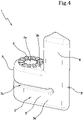
- the modular component 2 and the further modular component 2 are provided with adjusting teeth 6 (such as for example shown in figure 4 ) configured to snap adjust the relative angle between the two modular components 2. That is, the presence of the adjusting teeth 6 allows to obtain predefined or in any case more stable resting and/or stopping configurations (thus avoiding possible unwanted rotations of the modular components 2 if the connection members 7 are not sufficient).
- adjusting teeth 6 such as for example shown in figure 4
- both modular components 2 are provided with adjusting teeth 6 so as to define a toothed crown for adjusting the relative rotation between the modular components 2.
- the adjusting teeth 6 can be placed on one of the two base surfaces 3b and arranged around the axial fixing hole 5a. Even more preferably, with reference to and as depicted in figure 4 , the adjusting teeth 6 can be arranged on the upper base surface 3b.
- the modular component 2 can further comprise a support body 4.
- the support body 4 is arranged at the second end "B" and extends away from one of the base surfaces 3b (in figure 3 such a base surface 3b is the upper one and visible in the figure itself) and is configured to realize a further rest and/or a stop for a tool "U".
- the support body 4 realizes such a rest and/or stop in communion with the lateral wall 3a and/or the base walls 3b of the main body 3.
- the support body 4 defines an edge of the modular component 2 and is provided with one or more gaps 4a configured to contain the tools "U".
- the gaps 4a of two supports 1 installed close to each other on the wall or panel "P" can define a seat intended to accommodate and retain a tool "U", such as a screwdriver, blocking it by the handle.
- the gap 4a and the transversal cut 3c described above can be realized in the same embodiment of the modular component 2 as those described above.
- the support body 4 is perpendicular to the wall or panel "P" (in other words, the support body 4 is parallel to the normal position of the wall or panel "P").
- the support body 4 is parallel to the wall or panel "P".
- the modular component 2 and the further modular component 2 (when connected through the axial fixing hole 5a) can be connected with a first mounting configuration in which the respective support bodies 4 extend away from the main bodies 3 with the same direction, such as for example depicted in figure 7 .
- the modular component 2 and the further modular component 2 can be connected with a second mounting configuration in which the respective support bodies 4 extend away from the main bodies in the opposite direction, as depicted in figure 6 .
- the modular component 2 and the further modular component 2 can be connected in a third mounting configuration in which the respective support bodies 4 are positioned with a perpendicular and incident arrangement.
- the axial fixing hole 5a is further configured to define the connection for the further modular component 2 by means of a connection member 7 passing through the axial fixing hole 5a itself and the front fixing hole 5b of the further modular component 2 (such as for example depicted in figure 8B ).
- the choice of one of the mounting configurations is arbitrary as a function of the specific tool "U" to be supported and allows to obtain additional resting and/or stopping configurations.
- connection member 7 is a screw coupled to a removable expansion plug, it will not be necessary to completely unscrew the screw, allowing the undercut between the wall or panel "P" and the plug itself to be freed so that the user can hold the support 1 completely in his/her hand and move it where he/she most prefers easily.
- the present invention also relates to a support system 10 comprising a plurality of supports 1 as previously described (and therefore defined by one or more modular components 2 and by the different mounting or fixing configurations to the wall or panel "P", etc.).
- the support system 10 is also provided with a wall or panel "P".
- the wall or panel "P" can be perforated.
- the wall or panel can be provided with a standard type of drilling in which the holes have the dimensions 10 mm x 10 mm and a 38 mm pitch between each hole.
- other embodiments of the walls or panels "P" are achievable, such as for example walls or panels "P” provided with round holes, or wooden or plastic walls without holes on which to fix the supports with self-tapping screws.
- the support system 10 further comprises a plurality of connection members 7 configured to realize a reversible connection between one or more modular components 2 of the supports 1 for tools "U” and the wall or panel "P" so as to realize a plurality of resting and/or stopping points for tools "U".
- the connection members 7 can be selected from a screw, a clip, an insert, an expansion rivet or other similar means.
- the present invention is able to overcome the drawbacks which have emerged from the prior art.
- the support 1 for tools “U” and the support system 10 for tools “U” are versatile and can be used for a wide variety of tools “U” as a function of the different configurations described above.
- the support 1 for tools “U”, as well as the support system 10 for tools “U”, are easily mountable and removable, leading to a gain in time for a user.
Abstract
Description
- The present invention relates to a support for tools and a support system for tools.
- To date there are different types of supports connected or connectable to special walls or panels, usually perforated, in order to be able to realize a wall for tools. Generally, such perforated walls or panels have a standard type of drilling in which the holes have the
dimensions 10 mm x 10 mm and a 38 mm pitch between each hole. - Among the known supports there are various types, from those provided with special shapes to support a plurality of tools and/or special tools to generic ones, such as hooks, which allow to support only particular types of tools.
- The term tool refers to any type of instrument/equipment such as, for example, and hereby providing a non-exhaustive list: hammers, scissors, shears, wrenches, ropes, pipes, pliers, screwdrivers and similar. Therefore, given the variety of existing tools, a disadvantage of the known supports lies in the fact that they are designed for specific tools or that they cannot be used for a wide variety of tools, resulting in the purchase of specific hooks for each tool available and losing time finding the most suitable one.
- In addition, the current hooks of the prior art are in some cases dedicated to specific tools (and not transferable to all types of tools) and thus have reduced flexibility since they are not adaptable to future ranges of tools not yet in production.
- Further, the tools of the prior art can be bulky and/or expensive.
- The technical task of the present invention is thus to make available a support for tools and a support system for tools which are able to overcome the prior-art drawbacks which have emerged.
- An object of the present invention is therefore to provide a support for tools and a support system for tools which are versatile and usable for a wide variety of tools and which therefore favour reducing costs. Furthermore, a further object of the present invention is to provide a support for tools and a support system for tools which are easily mountable and removable so as to result in a gain in time by a user.
- The defined technical task and the specified aims are substantially achieved by a support for tools and a support system for tools comprising the technical features set forth in one or more of the appended claims.
- In particular, the technical task and the objects specified are substantially achieved by a support for tools comprising at least one modular component. The modular component comprises a main body, defining a lateral wall and two base surfaces and extending from a first end to a second end. The main body is configured to realize a rest and/or a stop for a tool.
- The main body is connectable to a wall or panel, preferably perforated walls or panels, according to a first fixing configuration, in which the base surfaces are parallel to the wall or panel, or a second fixing configuration in which the base surfaces are perpendicular to the wall or panel.
- The main body is further configured to realize a reversible connection between the modular component itself and a further modular component.
- Furthermore, the technical task and the specified aims are substantially achieved by a support system for tools comprising a plurality of supports for tools mentioned above, a wall or panel possibly perforated and a plurality of connection members configured to realize a reversible connection between one or more modular components of the supports for tools and the wall or panel so as to create a plurality of resting and/or stopping points for tools.
- Advantageously, the support for tools and the support system for tools are versatile and can be used for a wide variety of tools.
- Advantageously, the support for tools and the support system for tools are easily mountable and removable, leading to a gain in time for a user.
- Further features and advantages of the present invention will become more apparent from the indicative and thus non-limiting description of an embodiment of a support for tools and a support system for tools.
- This description will be set out below with reference to the appended drawings, which are provided solely for illustrative and therefore non-limiting purposes, in which:
-
Figures 1A-7 are schematic depictions of different embodiments of the support for tools object of the present invention. -
Figures 8A-8C are exemplary depictions of a support system for tools object of the present invention. - With reference to the appended
figures, 1 indicates in its entirety a support for tools which, for simplicity of description, will be referred to below assupport 1. - The term tool "U" refers to any type of instrument/equipment such as, for example and hereby providing a non-exhaustive list: hammers, scissors, shears, wrenches, ropes, pipes, pliers, screwdrivers and similar.
- The
support 1 comprises at least onemodular component 2 comprising amain body 3. - Preferably, the
modular component 2 can be made of plastic, composite, metallic or wood material. - Preferably, and as depicted for example in
figures 6 and7 , thesupport 1 can comprise twomodular components 2 connected together in manners which will be described in the following of the present description. - As depicted in
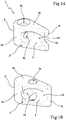
figure 1A , themain body 3 defines alateral wall 3a and twobase surfaces 3b. Themain body 3 extends from a first end "A" to a second end "B" with a substantially tapered shape. In other words, from the end "A" to the end "B" a transversal section of themain body 3 has a substantially decreasing trend. In the appended figures, themain body 3 has rounded edges but other shapes can be realized. - The
main body 3, i.e., the first end "A", the second end "B" and the lateral walls are configured to realize a rest and/or a stop for a tool "U". - In a further embodiment, such as for example that of
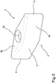
figure 2 , the main body 3 (i.e., thebase surfaces 3b) have a substantially rhomboidal shape. In a further embodiment, themain body 3 is provided with atransversal cut 3c, such as that shown infigures 4 and6 . Thetransversal cut 3c is parallel to thebase surfaces 3b and extends in a region of themain body 3 near the first end "A". Advantageously, thetransversal cut 3c allows to increase the elasticity of themodular component 2. - The
main body 3 is further connectable with a wall or panel "P", preferably a perforated wall or panel "P". Generally, such perforated walls or panels "P" have a standard type of drilling in which the holes have thedimensions 10 mm x 10 mm and a 38 mm pitch between each hole. However, other embodiments of the walls or panels "P" are achievable, such as walls or panels "P" provided with round holes. Preferably, themain body 3 is connectable to the wall or panel "P" at the end "A" or at one of thebase surfaces 3b - In particular, the
main body 3 is connectable to a wall or panel "P" according to a first fixing configuration, in which thebase surfaces 3b are parallel to the wall or panel "P", or a second fixing configuration in which the base surfaces are perpendicular to the wall or panel "P". - In the first fixing configuration, the
main body 3 rests on the wall or panel "P" through thebase surface 3b, while in the second fixing configuration themain body 3 rests on the wall or panel P through the end "A". Preferably, and as depicted in the appended figures, themain body 3 is provided with anaxial fixing hole 5a extending between the twobase surfaces 3b. - Preferably, as depicted in
figure 1A , theaxial fixing hole 5a extends at the first end "A". - Preferably, as depicted in
figures 1B and2 , theaxial fixing hole 5a extends in a central portion of themain body 3. - The
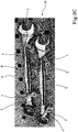
axial fixing hole 5a is configured to allow the connection of themain body 3 to the wall or panel "P" according to the first fixing configuration, such as for example shown infigure 8A . Such a fixing can be accomplished by means of aconnection member 7, such as a screw, clip, insert, expansion rivet or other similar means. - Preferably, the
main body 3 is provided with afront fixing hole 5b extending parallel to the two base surfaces and configured to allow the connection of themain body 3 to the wall or panel "P" according to the second fixing configuration. - Preferably, the
main body 3 can be provided with both theaxial fixing hole 5a and thefront fixing hole 5b. In this configuration, thefront fixing hole 5b can extend according to an extension axis thereof, extending between the first end "A" and the second end "B" and perpendicularly intersecting theaxial fixing hole 5a. - In this particular embodiment, the
main body 3 can be provided with an opening 5d suitable for allowing the passage of a connection member to connect themain body 3 to the wall or panel "P". This conformation is what allows maximum versatility to be obtained from thesupport 1 itself. Alternatively, such as for example depicted infigure 5 , thehole 5b can be arranged in the second end "B" and therefore extends for the entire extension of themain body 3. - Alternatively, the
front fixing hole 5b can extend near theaxial fixing hole 5a (therefore not intersecting it) so as to obtain a versatility similar to that of the previously described case. - Preferably, the
lateral surface 3a of themain body 3 has, near the first end "A", aresting surface 5c to the wall or panel "P" from which an end of thefront fixing hole 5b opens. Such a restingsurface 5c allows to obtain a stable resting of themain body 3 on the wall or panel "P" thus avoiding unwanted movements once it is fixed to the wall or panel "P" (for example by means of the aforementioned connection members 7). - The
main body 3 is further configured to realize a reversible connection between themodular component 2 itself and a furthermodular component 2 such as, for example, depicted infigures 6 and7 . A further reversible connection is illustrated infigure 8B where onemodular component 2, positioned axially, is connected with another modular component positioned frontally. That is, theresting surface 5c of the secondmodular element 2 is placed in contact with, and constrained by, thebase surface 3b crossed by theaxial fixing hole 5a. - Preferably, the
axial fixing hole 5a is further configured to define the connection for the furthermodular component 2 by means of aconnection member 7 passing through bothaxial fixing holes 5a of bothmodular components 2. Theconnection member 7 also allows to avoid unwanted movements between themodular components 2 once they have been connected to the wall or panel "P" and once the tool "U" has been positioned. - Preferably, the
modular component 2 and the furthermodular component 2, when connected, can be placed in relative rotation so as to obtain a plurality of resting and/or stopping configurations for specific tools "U". That is, depending on where the individual supports 1 on the wall or panel "P" and the specific tools "U" to be supported are connected, themodular components 2 are configured differently in order to hold resting and/or stopping the specific tools "U" to which they will be associated, such as for example depicted infigures 8A-8C . - In a possible embodiment, the
modular component 2 and the furthermodular component 2 are provided with adjusting teeth 6 (such as for example shown infigure 4 ) configured to snap adjust the relative angle between the twomodular components 2. That is, the presence of the adjustingteeth 6 allows to obtain predefined or in any case more stable resting and/or stopping configurations (thus avoiding possible unwanted rotations of themodular components 2 if theconnection members 7 are not sufficient). - Preferably, both
modular components 2 are provided with adjustingteeth 6 so as to define a toothed crown for adjusting the relative rotation between themodular components 2. - The adjusting
teeth 6 can be placed on one of the twobase surfaces 3b and arranged around theaxial fixing hole 5a. Even more preferably, with reference to and as depicted infigure 4 , the adjustingteeth 6 can be arranged on theupper base surface 3b. - Such as for example depicted in the embodiments of
figures 3-7 , themodular component 2 can further comprise asupport body 4. - The
support body 4 is arranged at the second end "B" and extends away from one of the base surfaces 3b (infigure 3 such abase surface 3b is the upper one and visible in the figure itself) and is configured to realize a further rest and/or a stop for a tool "U". Preferably, thesupport body 4 realizes such a rest and/or stop in communion with thelateral wall 3a and/or thebase walls 3b of themain body 3. - Preferably, such as for example depicted in
figures 3 and7 , thesupport body 4 defines an edge of themodular component 2 and is provided with one ormore gaps 4a configured to contain the tools "U". For example, thegaps 4a of twosupports 1 installed close to each other on the wall or panel "P" can define a seat intended to accommodate and retain a tool "U", such as a screwdriver, blocking it by the handle. - Although depicted in two different embodiments, the
gap 4a and thetransversal cut 3c described above can be realized in the same embodiment of themodular component 2 as those described above. When themain body 3 is connected to the wall or panel "P" according to the first fixing configuration (in which themain body 3 is connectable to the wall or panel "P" at thebase surface 3b from which thesupport body 4 does not extend), thesupport body 4 is perpendicular to the wall or panel "P" (in other words, thesupport body 4 is parallel to the normal position of the wall or panel "P"). - When the
main body 3 is connected to the wall or panel "P" according to the second fixing configuration, thesupport body 4 is parallel to the wall or panel "P". - Preferably, the
modular component 2 and the further modular component 2 (when connected through theaxial fixing hole 5a) can be connected with a first mounting configuration in which therespective support bodies 4 extend away from themain bodies 3 with the same direction, such as for example depicted infigure 7 . - Alternatively, the
modular component 2 and the further modular component 2 (when connected through theaxial fixing hole 5a) can be connected with a second mounting configuration in which therespective support bodies 4 extend away from the main bodies in the opposite direction, as depicted infigure 6 . - Further, the
modular component 2 and the furthermodular component 2 can be connected in a third mounting configuration in which therespective support bodies 4 are positioned with a perpendicular and incident arrangement. In this configuration theaxial fixing hole 5a is further configured to define the connection for the furthermodular component 2 by means of aconnection member 7 passing through theaxial fixing hole 5a itself and thefront fixing hole 5b of the further modular component 2 (such as for example depicted infigure 8B ). - The choice of one of the mounting configurations is arbitrary as a function of the specific tool "U" to be supported and allows to obtain additional resting and/or stopping configurations.
- The choice to use a single
modular component 2, or to use one or the other connection configuration of two or moremodular components 2, as well as the possibility of connecting to the wall or panel "P" according to the first or second fixing configuration, as well as the choice of the mounting configuration and the relative angle between one and the othermodular component 2 allow to define a plurality of resting and/or stopping configurations which allow to cover a wide variety of tools "U" to be supported. - Advantageously, both in the case of a
support 1 provided with a singlemodular component 2 and in the case of asupport 1 provided with bothmodular components 2, it is possible to obtain a rapid movement and therefore a rapid configuration of thesupport 1 without the need to completely remove theconnection member 7. For example, if theconnection member 7 is a screw coupled to a removable expansion plug, it will not be necessary to completely unscrew the screw, allowing the undercut between the wall or panel "P" and the plug itself to be freed so that the user can hold thesupport 1 completely in his/her hand and move it where he/she most prefers easily. - In the case of
modular elements 2, coupled together, it is possible to obtain the relative rotation between two modular elements mounted overlapping by loosening the fixingmember 7 and locking it again once the desired new orientation between the first and second elements has been obtained. - Furthermore, in the case of
modular elements 2 coupled together and provided with atransversal cut 3c, the relative rotation of the two modular elements mounted overlapping can be obtained without loosening the fixingmember 7, by exploiting the elasticity of the elements. - The present invention also relates to a
support system 10 comprising a plurality ofsupports 1 as previously described (and therefore defined by one or moremodular components 2 and by the different mounting or fixing configurations to the wall or panel "P", etc.). - The
support system 10 is also provided with a wall or panel "P". Preferably, the wall or panel "P" can be perforated. Even more preferably, the wall or panel can be provided with a standard type of drilling in which the holes have thedimensions 10 mm x 10 mm and a 38 mm pitch between each hole. However, other embodiments of the walls or panels "P" are achievable, such as for example walls or panels "P" provided with round holes, or wooden or plastic walls without holes on which to fix the supports with self-tapping screws. - The
support system 10 further comprises a plurality ofconnection members 7 configured to realize a reversible connection between one or moremodular components 2 of thesupports 1 for tools "U" and the wall or panel "P" so as to realize a plurality of resting and/or stopping points for tools "U". Preferably, theconnection members 7 can be selected from a screw, a clip, an insert, an expansion rivet or other similar means. Advantageously, the present invention is able to overcome the drawbacks which have emerged from the prior art. - Advantageously, the
support 1 for tools "U" and thesupport system 10 for tools "U" are versatile and can be used for a wide variety of tools "U" as a function of the different configurations described above. - Advantageously, the
support 1 for tools "U", as well as thesupport system 10 for tools "U", are easily mountable and removable, leading to a gain in time for a user.
Claims (14)
- A support (1) for tools (U) comprising at least one modular component (2) comprising a main body (3), defining a lateral wall (3a) and two base surfaces (3b) and extending from a first end (A) to a second end (B) configured to realize a rest and/or a stop for a tool (U),said main body (3) being connectable to a wall or panel (P), preferably perforated walls or panels (P), according to a first fixing configuration, wherein said base surfaces (3b) are parallel to the wall or panel (P), or a second fixing configuration wherein said base surfaces are perpendicular to said wall or panel (P);said main body (3) being further configured to realize a reversible connection between said modular component (2) and one or more further modular components (2);wherein said main body (3) is further provided with a front fixing hole (5b) extending parallel to said two base surfaces (3b) and configurated to allow the connection of said main body (3) to said wall or panel (P) according to said second fixing configuration.
- The support (1) according to claim 1, wherein said base surfaces have a substantially rhomboidal shape.
- The support (1) according to claim 1, wherein said main body extends from said first end to said second end with a substantially tapered shape.
- The support (1) according to one or more of the preceding claims, wherein said modular component further comprises a support body (4), arranged at said second end (B) and extending away from one of said base surfaces (3b) of the base body (3), configured to realize a further rest and/or a stop for a tool (U), said support body being perpendicular to said wall or panel (P) when said main body (3) is connected according to the first fixing configuration and being parallel to said wall or panel (P) when said main body (3) is connected according to the second fixing configuration.
- The support (1) according to one or more of the preceding claims, wherein said main body (3) is provided with an axial fixing hole (5a), extending between said two base surfaces (3b), preferably in said first end (A), and configured to allow the connection of said main body (3) to said wall or panel (P) according to said first fixing configuration.
- The support (1) according to claim 5, wherein said front fixing hole (5a) extends according to an extension axis thereof extending between said first and second ends (A, B) and intersecting perpendicularly said axial fixing hole (5a), said lateral surface (3a) of the main body (3) having, near the first end (A), a resting surface (5c) to said wall or panel (P) from which an end of the front fixing hole (5b) opens.
- The support (1) according to one or more of claims 5-6, wherein said axial fixing hole (5a) is further configured to define said connection for the further modular component (2) by means of a connection member (7) passed through both axial fixing holes (5a) of both modular components (2).
- The support (1) according to claim 7, wherein said modular component (2) and said further modular component (2), when connected, can be placed in relative rotation so as to obtain a plurality of resting and/or stopping configurations for specific tools (U).
- The support (1) according to claim 8, wherein at least one of said modular component (2) and said further modular component (2) is provided with adjusting teeth (6) configured to snap adjust the relative angle between the two modular components (2), preferably both modular components (2) are provided with said adjusting teeth (6) defining a toothed crown for adjusting the relative rotation between the modular components (2).
- The support (1) according to one or more of claims 7-9 when dependent on 4, wherein said modular component (2) and said further modular component (2) can be connected with a first mounting configuration, wherein the respective support bodies (4) extend away from the main bodies (3) in the same direction, or with a second mounting configuration, wherein the respective support bodies (4) extend away from the main bodies (3) in the opposite direction.
- The support (1) according to one or more of claims 1 and 5 or claim 6, wherein the axial fixing hole (5a) is further configured to define said connection for the further modular component (2) by means of a connection member (7) passing through the axial fixing hole (5a) itself and the front fixing hole (5b) of the further modular component (2).
- The support (1) according to claim 3 or 4, wherein said main body (3) has at said first or second end or at a support body (4) one or more gaps (4a) configured to contain the tools (U).
- The support (1) according to one or more of the preceding claims, wherein said main body is provided with a transversal cut (3c), parallel to said base surfaces (3b), extending near said first end (A) of the main body (3); said transversal cut (3c), in the case of connection of two or more modular elements (2), favouring the relative rotation of one modular element (2) with respect to another without loosening the grip of a connection member (7).
- A support system (10) for tools (U) comprising a plurality of supports (1) for tools (U) according to one or more of the preceding claims, a wall or panel (P), preferably a perforated wall or panel (P), and a plurality of connection members (7) configured to realize a reversible connection between one or more modular components (2) of the supports (1) and the wall or panel (P) so as to create a plurality of resting and/or stopping points for tools (U).
Applications Claiming Priority (2)
| Application Number | Priority Date | Filing Date | Title |
|---|---|---|---|
| IT102020000012709A IT202000012709A1 (en) | 2020-05-28 | 2020-05-28 | TOOL HOLDER AND TOOL HOLDER SYSTEM |
| EP21167565.7A EP3915733B1 (en) | 2020-05-28 | 2021-04-09 | Support for tools and support system for tools |
Related Parent Applications (2)
| Application Number | Title | Priority Date | Filing Date |
|---|---|---|---|
| EP21167565.7A Division-Into EP3915733B1 (en) | 2020-05-28 | 2021-04-09 | Support for tools and support system for tools |
| EP21167565.7A Division EP3915733B1 (en) | 2020-05-28 | 2021-04-09 | Support for tools and support system for tools |
Publications (2)
| Publication Number | Publication Date |
|---|---|
| EP4005741A1 true EP4005741A1 (en) | 2022-06-01 |
| EP4005741B1 EP4005741B1 (en) | 2024-03-13 |
Family
ID=72178979
Family Applications (2)
| Application Number | Title | Priority Date | Filing Date |
|---|---|---|---|
| EP21167565.7A Active EP3915733B1 (en) | 2020-05-28 | 2021-04-09 | Support for tools and support system for tools |
| EP22152187.5A Active EP4005741B1 (en) | 2020-05-28 | 2021-04-09 | Support for tools and support system for tools |
Family Applications Before (1)
| Application Number | Title | Priority Date | Filing Date |
|---|---|---|---|
| EP21167565.7A Active EP3915733B1 (en) | 2020-05-28 | 2021-04-09 | Support for tools and support system for tools |
Country Status (5)
| Country | Link |
|---|---|
| US (1) | US11358273B2 (en) |
| EP (2) | EP3915733B1 (en) |
| ES (1) | ES2927148T3 (en) |
| IT (1) | IT202000012709A1 (en) |
| PL (1) | PL3915733T3 (en) |
Families Citing this family (1)
| Publication number | Priority date | Publication date | Assignee | Title |
|---|---|---|---|---|
| USD985346S1 (en) * | 2020-10-22 | 2023-05-09 | Fami S.R.L. | Tool turning support |
Citations (5)
| Publication number | Priority date | Publication date | Assignee | Title |
|---|---|---|---|---|
| US3265032A (en) * | 1965-10-23 | 1966-08-09 | Patrick H Hume | Cam cleat |
| US6575313B1 (en) * | 2002-02-27 | 2003-06-10 | E-Make Co., Ltd. | Structure for firmly resting tools thereon |
| US20130105655A1 (en) * | 2011-10-26 | 2013-05-02 | Mark Chen | Article holder |
| EP3028756A1 (en) * | 2013-07-31 | 2016-06-08 | Lee, Xi-Wei | Pieced structure of building block toy |
| CN207126138U (en) * | 2017-08-14 | 2018-03-23 | 深圳市青苗创客科技有限公司 | A kind of convenient assembly type electronic building blocks module |
Family Cites Families (5)
| Publication number | Priority date | Publication date | Assignee | Title |
|---|---|---|---|---|
| US5799915A (en) * | 1995-01-31 | 1998-09-01 | The Burton Corporation | Twist rack for snowboards |
| EP1120576B1 (en) * | 2000-01-24 | 2003-11-12 | Eric Thompson | Toolless locking mount |
| US20070120021A1 (en) * | 2005-11-11 | 2007-05-31 | Yu-Shen Lin | Hanging clamp for different size rods |
| US9193063B2 (en) * | 2014-03-10 | 2015-11-24 | Kevin Huang | Tool positioning pad |
| US10629335B2 (en) * | 2014-10-31 | 2020-04-21 | Panduit Corp. | Wire harness assembly system |
-
2020
- 2020-05-28 IT IT102020000012709A patent/IT202000012709A1/en unknown
-
2021
- 2021-02-11 US US17/173,450 patent/US11358273B2/en active Active
- 2021-04-09 ES ES21167565T patent/ES2927148T3/en active Active
- 2021-04-09 PL PL21167565.7T patent/PL3915733T3/en unknown
- 2021-04-09 EP EP21167565.7A patent/EP3915733B1/en active Active
- 2021-04-09 EP EP22152187.5A patent/EP4005741B1/en active Active
Patent Citations (5)
| Publication number | Priority date | Publication date | Assignee | Title |
|---|---|---|---|---|
| US3265032A (en) * | 1965-10-23 | 1966-08-09 | Patrick H Hume | Cam cleat |
| US6575313B1 (en) * | 2002-02-27 | 2003-06-10 | E-Make Co., Ltd. | Structure for firmly resting tools thereon |
| US20130105655A1 (en) * | 2011-10-26 | 2013-05-02 | Mark Chen | Article holder |
| EP3028756A1 (en) * | 2013-07-31 | 2016-06-08 | Lee, Xi-Wei | Pieced structure of building block toy |
| CN207126138U (en) * | 2017-08-14 | 2018-03-23 | 深圳市青苗创客科技有限公司 | A kind of convenient assembly type electronic building blocks module |
Also Published As
| Publication number | Publication date |
|---|---|
| PL3915733T3 (en) | 2022-10-24 |
| EP3915733A1 (en) | 2021-12-01 |
| IT202000012709A1 (en) | 2021-11-28 |
| US11358273B2 (en) | 2022-06-14 |
| ES2927148T3 (en) | 2022-11-02 |
| EP3915733B1 (en) | 2022-08-24 |
| US20210370492A1 (en) | 2021-12-02 |
| EP4005741B1 (en) | 2024-03-13 |
Similar Documents
| Publication | Publication Date | Title |
|---|---|---|
| CA1290682C (en) | Cutter head for cutters | |
| US11357328B2 (en) | Furniture securing device | |
| EP4005741A1 (en) | Support for tools and support system for tools | |
| US7493671B2 (en) | Adjustable trowel assembly | |
| US20230183972A1 (en) | Ceiling system | |
| US20020043429A1 (en) | Ladder pan | |
| US7603780B2 (en) | Multi-purpose tool | |
| US7261213B2 (en) | Closet partition system | |
| US5105704A (en) | Adjustable saw blade fastener | |
| CN114198374A (en) | A connecting system for connecting at least two, in particular plate-like, elements; assembly comprising such a connection system | |
| US5913381A (en) | Friction sawhorse bracket | |
| US20180142870A1 (en) | Push-on mechanical fastener for lighting fixture | |
| GB2285940A (en) | Fastening system | |
| JP5632941B1 (en) | Fastener mounting device and fastener mounting structure | |
| EP3012536B1 (en) | Gas hob | |
| US7549819B2 (en) | Device comprising two hollow profiles that are held together by means of a connecting screw, and corresponding tool | |
| US7051914B2 (en) | Fastening apparatus with bearing shoe and positioning plate | |
| JP2016116321A (en) | Fastening fixture | |
| JP6918349B2 (en) | Lifeline engagement device | |
| US5833419A (en) | Angularly accessible head for threaded connector | |
| JP7228988B2 (en) | Mounting members and equipment | |
| DK179677B1 (en) | FITTING MOUNT FOR MAINTENANCE OF A BUILDING ELEMENT | |
| JP2011184937A (en) | Fitting frame adjusting implement and fitting frame adjusting structure using the same | |
| TW202124852A (en) | Fastening device | |
| EP3698926A1 (en) | Tool fixing system for a tool cart |
Legal Events
| Date | Code | Title | Description |
|---|---|---|---|
| PUAI | Public reference made under article 153(3) epc to a published international application that has entered the european phase |
Free format text: ORIGINAL CODE: 0009012 |
|
| STAA | Information on the status of an ep patent application or granted ep patent |
Free format text: STATUS: THE APPLICATION HAS BEEN PUBLISHED |
|
| AC | Divisional application: reference to earlier application |
Ref document number: 3915733 Country of ref document: EP Kind code of ref document: P |
|
| AK | Designated contracting states |
Kind code of ref document: A1 Designated state(s): AL AT BE BG CH CY CZ DE DK EE ES FI FR GB GR HR HU IE IS IT LI LT LU LV MC MK MT NL NO PL PT RO RS SE SI SK SM TR |
|
| STAA | Information on the status of an ep patent application or granted ep patent |
Free format text: STATUS: REQUEST FOR EXAMINATION WAS MADE |
|
| 17P | Request for examination filed |
Effective date: 20221124 |
|
| RBV | Designated contracting states (corrected) |
Designated state(s): AL AT BE BG CH CY CZ DE DK EE ES FI FR GB GR HR HU IE IS IT LI LT LU LV MC MK MT NL NO PL PT RO RS SE SI SK SM TR |
|
| GRAP | Despatch of communication of intention to grant a patent |
Free format text: ORIGINAL CODE: EPIDOSNIGR1 |
|
| STAA | Information on the status of an ep patent application or granted ep patent |
Free format text: STATUS: GRANT OF PATENT IS INTENDED |
|
| INTG | Intention to grant announced |
Effective date: 20231219 |
|
| GRAS | Grant fee paid |
Free format text: ORIGINAL CODE: EPIDOSNIGR3 |
|
| GRAA | (expected) grant |
Free format text: ORIGINAL CODE: 0009210 |
|
| STAA | Information on the status of an ep patent application or granted ep patent |
Free format text: STATUS: THE PATENT HAS BEEN GRANTED |
|
| AC | Divisional application: reference to earlier application |
Ref document number: 3915733 Country of ref document: EP Kind code of ref document: P |
|
| AK | Designated contracting states |
Kind code of ref document: B1 Designated state(s): AL AT BE BG CH CY CZ DE DK EE ES FI FR GB GR HR HU IE IS IT LI LT LU LV MC MK MT NL NO PL PT RO RS SE SI SK SM TR |
|
| REG | Reference to a national code |
Ref country code: GB Ref legal event code: FG4D |
|
| REG | Reference to a national code |
Ref country code: CH Ref legal event code: EP |
|
| REG | Reference to a national code |
Ref country code: DE Ref legal event code: R096 Ref document number: 602021010515 Country of ref document: DE |