EP4005730A1 - Machine tool with an automatic lubricating system and related lubricating method - Google Patents
Machine tool with an automatic lubricating system and related lubricating method Download PDFInfo
- Publication number
- EP4005730A1 EP4005730A1 EP21209755.4A EP21209755A EP4005730A1 EP 4005730 A1 EP4005730 A1 EP 4005730A1 EP 21209755 A EP21209755 A EP 21209755A EP 4005730 A1 EP4005730 A1 EP 4005730A1
- Authority
- EP
- European Patent Office
- Prior art keywords
- lubricant dispenser
- lubricant
- machine tool
- opening
- dispenser
- Prior art date
- Legal status (The legal status is an assumption and is not a legal conclusion. Google has not performed a legal analysis and makes no representation as to the accuracy of the status listed.)
- Granted
Links
Images



Classifications
-
- B—PERFORMING OPERATIONS; TRANSPORTING
- B27—WORKING OR PRESERVING WOOD OR SIMILAR MATERIAL; NAILING OR STAPLING MACHINES IN GENERAL
- B27C—PLANING, DRILLING, MILLING, TURNING OR UNIVERSAL MACHINES FOR WOOD OR SIMILAR MATERIAL
- B27C3/00—Drilling machines or drilling devices; Equipment therefor
- B27C3/04—Stationary drilling machines with a plurality of working spindles
-
- B—PERFORMING OPERATIONS; TRANSPORTING
- B23—MACHINE TOOLS; METAL-WORKING NOT OTHERWISE PROVIDED FOR
- B23Q—DETAILS, COMPONENTS, OR ACCESSORIES FOR MACHINE TOOLS, e.g. ARRANGEMENTS FOR COPYING OR CONTROLLING; MACHINE TOOLS IN GENERAL CHARACTERISED BY THE CONSTRUCTION OF PARTICULAR DETAILS OR COMPONENTS; COMBINATIONS OR ASSOCIATIONS OF METAL-WORKING MACHINES, NOT DIRECTED TO A PARTICULAR RESULT
- B23Q1/00—Members which are comprised in the general build-up of a form of machine, particularly relatively large fixed members
- B23Q1/0009—Energy-transferring means or control lines for movable machine parts; Control panels or boxes; Control parts
- B23Q1/0018—Energy-transferring means or control lines for movable machine parts; Control panels or boxes; Control parts comprising hydraulic means
-
- B—PERFORMING OPERATIONS; TRANSPORTING
- B23—MACHINE TOOLS; METAL-WORKING NOT OTHERWISE PROVIDED FOR
- B23Q—DETAILS, COMPONENTS, OR ACCESSORIES FOR MACHINE TOOLS, e.g. ARRANGEMENTS FOR COPYING OR CONTROLLING; MACHINE TOOLS IN GENERAL CHARACTERISED BY THE CONSTRUCTION OF PARTICULAR DETAILS OR COMPONENTS; COMBINATIONS OR ASSOCIATIONS OF METAL-WORKING MACHINES, NOT DIRECTED TO A PARTICULAR RESULT
- B23Q11/00—Accessories fitted to machine tools for keeping tools or parts of the machine in good working condition or for cooling work; Safety devices specially combined with or arranged in, or specially adapted for use in connection with, machine tools
- B23Q11/10—Arrangements for cooling or lubricating tools or work
- B23Q11/1015—Arrangements for cooling or lubricating tools or work by supplying a cutting liquid through the spindle
-
- B—PERFORMING OPERATIONS; TRANSPORTING
- B23—MACHINE TOOLS; METAL-WORKING NOT OTHERWISE PROVIDED FOR
- B23Q—DETAILS, COMPONENTS, OR ACCESSORIES FOR MACHINE TOOLS, e.g. ARRANGEMENTS FOR COPYING OR CONTROLLING; MACHINE TOOLS IN GENERAL CHARACTERISED BY THE CONSTRUCTION OF PARTICULAR DETAILS OR COMPONENTS; COMBINATIONS OR ASSOCIATIONS OF METAL-WORKING MACHINES, NOT DIRECTED TO A PARTICULAR RESULT
- B23Q11/00—Accessories fitted to machine tools for keeping tools or parts of the machine in good working condition or for cooling work; Safety devices specially combined with or arranged in, or specially adapted for use in connection with, machine tools
- B23Q11/12—Arrangements for cooling or lubricating parts of the machine
- B23Q11/121—Arrangements for cooling or lubricating parts of the machine with lubricating effect for reducing friction
- B23Q11/122—Lubricant supply devices
Definitions
- the present invention relates to a machine tool with an automatic lubricating system and related lubricating method.
- the invention relates to a machine tool for machining wood panels and the like, such as wood fiber, plastic, or fiberglass panels, comprising parts to be periodically lubricated, in particular spindles, and an automatic lubrication system, to lubricate these spindles.
- the present invention also relates to a method of automatic lubrication of such spindles.
- machine tools for working wooden panels and the like usually comprise: a working surface, on which to arrange a panel to be machined; at least one operating head, capable to moving relative to the working surface, comprising at least one spindle; and at least one tool or machining member, for example, a plurality of drilling bits, which can be coupled to said at least one spindle of the operating head, for machining the panel to be machined arranged on the working surface.
- such manual lubrication can easily be subject to human error.
- the operator could not treat a spindle to be lubricated, especially in the case in which the mobile assembly includes a large number of spindles, or he could lubricate these spindles with an incorrect quantity of lubricant.
- An alternative solution to the manual lubrication provides for the realization of an operating head equipped with an automatic lubrication system, which comprises a plurality of stable connections between a lubricant reservoir and the different spindles of the operating head.
- the object of the present invention is to provide a machine tool for the machining of panels and the like, which allows the automatic lubrication of the spindles or of the rotary members assigned to receive the tools for the execution of the foreseen processes, while avoiding the need to make changes to the machine that limits its operation and increase its cost.
- the object of the present invention is that this machine tool allows minimizing the lubrication times of the spindles.
- Another object of the invention proposed here is that the operating members of this machine tool are scarcely subject to breakage.
- a further object of the present invention is that this machine tool is simple to use, safe and reliable.
- the object of the present invention is that this machine tool is of reduced dimensions.
- Still another object of the present invention is that this machine tool minimizes maintenance costs.
- the object of the present invention is to provide an automatic method for the spindles lubrication that is quick, safe and reliable, if compared to the prior art.
- a machine tool in particular for machining elements to be machined such as wooden panels and similar, comprising: a working surface, for receiving an element to be machined; at least one operative head, movable relative to said element to be machined, and comprising
- Said machine tool comprises, also, a lubricant dispenser, able to be coupled to said at least one opening, said lubricant dispenser being configured for dispensing, when activated, said lubricant.
- said machine comprises also a control unit, for controlling the movement of said operative head and/or of said lubricant dispenser.
- Said control unit is configured to command at least one mutual movement between said operative head and said lubricant dispenser, to couple said lubricant dispenser to said at least one opening, and to activate said lubricant dispenser such that said lubricant dispenser supplies said lubricant into said at least one lubricating conduit through said at least one opening, to lubricate said at least one spindle.
- this such dispensing can take place after the coupling between the lubricant dispenser and said at least one opening.
- such lubricant dispenser may be configured to be activated by means of an electric command, and/or a pneumatic command, and/or by exercising a pressure.
- said lubricant dispenser is configured for being activated by exercising a pressure, and in that said control unit is configured to command said at least one mutual movement between said operative head and said lubricant dispenser such that said operative head exercises said pressure on the lubricant dispenser.
- said lubricant dispenser may comprise a tank for containing said lubricant and a dispensing pump in fluid connection with said tank.
- Said dispensing pump may be configured for dispensing said lubricant from said tank when subjected to said pressure.
- said operative head may be movable along at least one axis, preferably a vertical axis.
- said lubricant dispenser may be placed on said axis, and said control unit may be configured for moving said operative head at least along said axis.
- said lubricant dispenser may be removable with respect to said machine tool.
- said lubricant dispenser may be connectable with said working surface.
- said lubricant dispenser may be movable between a resting configuration, where said lubricant dispenser is completely placed below said working surface, and an operative configuration, where said lubricant dispenser protrudes at least partially above said working surface.
- said machine tool may comprise at least one pair of supporting elements, defining said working surface and placed apart from each other.
- said lubricant dispenser may be placed between said supporting elements.
- said operative head may comprise a plurality of spindles.
- a lubricating conduit may be provided, which is associated with each spindle, and a plurality of openings, preferably a respective opening for each lubricating conduit, may be provided.
- said lubricant dispenser may be able to be simultaneously coupled to a plurality of said openings, in particular to all said openings.
- said step B may be executed by means of an electric command, and/or a pneumatic command, and/or by exercising a pressure.
- said operative head comprises a plurality of spindles, a plurality of lubricating conduits in fluid communication with said plurality of spindles, and a plurality of openings in which said plurality of lubricating conduits ends.
- steps A. and B. are repeated for each opening of said plurality of openings.
- said step A may comprise simultaneously coupling said lubricant dispenser with a plurality of said openings, in particular with all said openings.
- a machine tool 1 can be seen, in particular a drilling machine 1, for machining wooden panels P and the like according to the present invention, comprising
- the operating heads 3 are movable relative to the working surface.
- the machine tool 1 in fact comprises
- first pair of supporting elements 11' and a second pair of supporting elements 11", spaced from said first pair, in which the supporting elements 11' of said first pair are separated one from the other to form a housing 12 between them to house the lubricant dispenser 5.
- the supporting elements 11', 11" also comprise respective supporting surfaces 110, or shelves 110, coplanar with each other, which they define the working surface 2.
- the panel P during use, rests on the four support surfaces 110 of the supporting elements 11', 11".
- the working surface 2 can be formed by elements other than those described, and can also be fixed.
- the working surface 2 can be formed by elements other than those described, and can also be fixed.
- only a pair of supporting elements 11' can be present, in particular a pair of fixed supporting elements 11'.
- the machine tool 1 may not comprise said tracks 100.
- the number of operating heads 3 of the machine tool 1 can be different from four, as there may also be only one operating head 3.
- control unit can be of the programmable type and can comprise or be connected to storage means for memorizing the position of the various elements connected to it.
- the same control unit can also be configured to control the displacements of the supporting elements 11', 11" along the tracks 100.
- the lubricant dispenser 5 shown in figures 1-9 comprises a tank 50 containing lubricant, for example grease, and a dispensing pump 51 in fluid connection with the tank 50.
- the dispensing pump 51 is configured to deliver lubricant from the tank 50 when operated, particularly when subjected to pressure. Said pressure can be exerted by the operating head, but it is possible to provide that this pressure is exerted by a special device not integral with the operating head.
- command can mean both a sensor element, for example a proximity and/or contact sensor, and an actuator element, for example an electric and/or pneumatic actuator.
- the dispensing pump 51 can be equipped with a suitable valve, in particular a spherical valve, to prevent the undesired leakage of lubricant.
- the lubricant dispenser 5 has a substantially vertical development.
- the dispensing pump 51 is a stem arranged along a vertical Z-axis, orthogonal to the horizontal X-axis, for the reasons illustrated below.
- the lubricant dispenser 5 is arranged inside the housing 12 between the supporting elements 11' and coupled to one of them, thus forming a lubrication station or greasing station for the spindles of the operating heads 3.
- Spindle lubrication means the lubrication of the parts of the spindles most subject to wear, such as bearings and/or gears for motion transmission.
- the lubricant dispenser 5 is configured to move along the vertical Z-axis, between a rest configuration, in which it is arranged below the working surface 2 (see figure 5 ), and an operating configuration (see figure 6 ), in which at least the dispensing pump 51 protrudes above the working surface 2, for the reasons illustrated below.
- the movement of the lubricant dispenser 5 can also take place under the control of said control unit.
- the lubricant dispenser 5 is associated with the working surface 2.
- this arrangement of the lubricant dispenser 5, and in particular the fact that it is associated with the working surface 2, allows minimizing the overall dimensions of the machine tool 1 for the reasons illustrated below.
- the lubricant dispenser 5 can be coupled to different elements of the machine tool 1, for example to a longitudinal member 10 or another part of the frame, or to a further mobile element of the machine tool 1.
- the lubricant dispenser 5 can be arranged in a lubrication area separated from the working surface 2.
- the coupling between the lubricant dispenser 5 and the machine tool 1 can be of the removable type, to facilitate the refilling the tank 50.
- an operating head 3 of a machine tool 1 comprises a plurality of spindles 30, on which drilling bits 4 can be removably mounted for drilling the panel P arranged on the underlying working surface 2.
- other working parts for panels P in addition to the aforementioned drilling bits 4, may be mounted on the spindles 30; moreover, the number of spindles 30 can vary, since, in hypothesis, even only one spindle 30 may be present.
- the operating head 3 is configured in such a way as to be able to move, under the action of said control unit, at least along the vertical Z-axis to go down towards the panel P and perform the drilling operations on it provided by the working program in execution.
- the operating head 3 can move according to the vertical Z-axis and the horizontal X-axis, to allow the machining of different types of panels P.
- the operating head 3 also comprises a plurality of lubrication ducts 31 in fluid connection with the outside through a respective opening 32, for the insertion of lubricant, and with a respective spindle 30, so as to allow the lubrication of the spindle 30 by inserting lubricant through the opening 32.
- figure 4 shows an operating head 3 comprising a lubrication duct 31 and a respective opening 32 for each spindle 30.
- openings 32 are arranged close to each other, being concentrated on suitable portions 320 of the operating head 3. This allows limiting the movements of the operating head 3 during the automatic lubrication of the spindles 30, which will be illustrated below, and, consequently, to reduce the times' machine downtime for the execution of this automatic lubrication.
- the portions 320 in which the openings 32 are formed are projecting with respect to the spindles 30, to facilitate this automatic lubrication step.
- the number of openings 32 and/or of lubrication ducts 31 can be different from the number of the spindles 30, for example, an opening 32 can be provided, into which more lubrication ducts 31 open in their turn in fluid connection with the relative spindles 30.
- the opening 32 can be coupled to the dispensing pump 51 of the lubricant dispenser 5, by means of the method illustrated below.
- a further embodiment comprises a lubricant dispenser 5, which can be coupled simultaneously to a plurality of said openings 32.
- the lubricant dispenser 5 comprises a plurality of dispensing pumps 51 in fluid connection with a single tank 50, or with a plurality of respective tanks 50.
- Each opening 32 can also be provided with a suitable valve to prevent dripping of the lubricant onto the working surface 2 and/or onto the panel P to be machined.
- the operating head 3 is moving away from the underlying panel P arranged on the working surface 2, after having performed the drilling operations on the latter by means of the drilling bits 4, while the lubricant dispenser 5 is in the respective rest configuration inside the housing 12, i.e. between the two supporting elements 11'.
- the panel P can be moved on the working plane, during the work itself, for example along a horizontal axis orthogonal to the X-axis.
- control unit arranges the lifting of the lubricant dispenser 5 in the operating configuration, and the vertical alignment, along the vertical Z-axis, between an opening 32 of the operating head 3 and the dispensing pump 51.
- the lubricant dispenser 5 is arranged in correspondence with the working surface 2, the advantage is obtained of limiting the displacements of the operating head 3 to carrying out the lubrication operations. This makes it possible to produce machine tools 1 of contained dimensions.
- the lubricant dispenser 5 may not be associated with the working surface 2, being for example arranged in a lubrication area separated from it. In this case, the operating head 3 and/or the lubricant dispenser 5 will have to perform longer strokes than in the case illustrated above, in order to carry out the lubrication operations.
- control unit arranges the lowering of the operating head 3 along the vertical Z-axis until contact, i.e. coupling, is achieved between the aforementioned opening 32 and the dispensing pump 51.
- the control unit commands a further lowering of the operating head 3 along the vertical Z-axis, so that the operating head 3 activates the dispensing pump 51, in particular by exerting said pressure on the dispensing pump 51 and causing its stem to lower, for the delivery of the lubricant in the lubrication duct 31 connected to said opening 32 and the consequent lubrication of the respective spindle 30.
- a fourth lubrication step shown in figure 9 , the control unit arranges the lifting of the operating head 3 along the vertical Z-axis, thus interrupting the passage of the lubricant from the dispensing pump 51 to the lubrication duct 31.
- the lubrication steps can therefore be repeated for each opening 32 present on the operating head 3.
- the lubrication steps can take place by keeping the operating head in one position and moving, directly or indirectly, through the control unit, only the lubricant dispenser 5, or both the lubricant dispenser 5 and the operating head 3, in such a way as to obtain in any case the reciprocal coupling between the dispensing pump 51 and an opening 32 of the operating head 3.
- an automatic lubrication method of a spindle 30, which can be actuated by a control unit of a machine tool 1 of the type described, may comprise the following steps:
- control unit operates the dispensing pump 51 by means of an electric control, and/or a pneumatic control, and/or the exertion of a pressure.
- step B it is possible to command a reciprocal approach between the operating head 3 and the dispensing pump 51, so that said pressure is exerted on the dispensing pump 51 through the operating head 3.
- this automatic method can comprise the following substeps of step A.:
- the steps A. and B. can be repeated for each opening 32 connected to the lubrication ducts 31 of the operating head 3.
- step A comprises the simultaneous coupling of a plurality of dispensing pumps 51 (not shown) of a lubricant dispenser 5 to a plurality of openings 32, preferably to all openings 32 connected to the lubrication ducts 31 of the operating head.
- a plurality of dispensing pumps 51 not shown
- a lubricant dispenser 5 to a plurality of openings 32, preferably to all openings 32 connected to the lubrication ducts 31 of the operating head.
- the machine tool 1 and the automatic lubrication method described make it possible to automate the lubrication of the spindles 30, advantageously reducing the machine downtime and the related maintenance costs.
- the machine tool 1 is advantageously safer than the machines of the known art.
- the machine tool 1 does not have larger dimensions than the machines of the prior art, which provide for the manual lubrication of the spindles 30.
- machine tool 1 described can be advantageously adapted to different types of operating heads 3 with different arrangements of the spindles 30 and of the relative openings 32, simply by reprogramming the control unit.
Landscapes
- Engineering & Computer Science (AREA)
- Mechanical Engineering (AREA)
- Life Sciences & Earth Sciences (AREA)
- Wood Science & Technology (AREA)
- Forests & Forestry (AREA)
- Auxiliary Devices For Machine Tools (AREA)
Abstract
Description
- The present invention relates to a machine tool with an automatic lubricating system and related lubricating method.
- More in detail, the invention relates to a machine tool for machining wood panels and the like, such as wood fiber, plastic, or fiberglass panels, comprising parts to be periodically lubricated, in particular spindles, and an automatic lubrication system, to lubricate these spindles.
- The present invention also relates to a method of automatic lubrication of such spindles.
- In the following, the description will be directed to a machine tool for working wooden panels and the like comprising spindles to be periodically lubricated. However, it is clear that the same description should not be considered limited to this specific use, but it can be applied to any machine tool comprising parts to be lubricated.
- As is well known, machine tools for working wooden panels and the like usually comprise: a working surface, on which to arrange a panel to be machined; at least one operating head, capable to moving relative to the working surface, comprising at least one spindle; and at least one tool or machining member, for example, a plurality of drilling bits, which can be coupled to said at least one spindle of the operating head, for machining the panel to be machined arranged on the working surface.
- The moving parts of these machines, and in particular the spindles, require to be periodically lubricated to ensure the correct operation of the machine tool itself. This lubrication is usually done manually by an operator, after stopping the machine.
- This involves frequent and long periods of machine downtime, especially in the case of a machine tool comprising a plurality of spindles, with consequent high maintenance costs.
- Furthermore, such manual lubrication can easily be subject to human error. By way of example, the operator could not treat a spindle to be lubricated, especially in the case in which the mobile assembly includes a large number of spindles, or he could lubricate these spindles with an incorrect quantity of lubricant.
- An alternative solution to the manual lubrication, described above, provides for the realization of an operating head equipped with an automatic lubrication system, which comprises a plurality of stable connections between a lubricant reservoir and the different spindles of the operating head.
- This alternative, while overcoming the limits of the manual solution, involves the creation on the operating head of a complicated system of lubrication ducts and electrical cables, considerably increasing the construction costs of the machine and limiting the movements that the operating head can perform during the processing.
- In light of the above, it is therefore an object of the present invention to provide a machine tool that overcomes the problems of the prior art.
- In particular, the object of the present invention is to provide a machine tool for the machining of panels and the like, which allows the automatic lubrication of the spindles or of the rotary members assigned to receive the tools for the execution of the foreseen processes, while avoiding the need to make changes to the machine that limits its operation and increase its cost.
- Furthermore, the object of the present invention is that this machine tool allows minimizing the lubrication times of the spindles.
- Another object of the invention proposed here is that the operating members of this machine tool are scarcely subject to breakage.
- A further object of the present invention is that this machine tool is simple to use, safe and reliable.
- Furthermore, the object of the present invention is that this machine tool is of reduced dimensions.
- Still another object of the present invention is that this machine tool minimizes maintenance costs.
- Finally, the object of the present invention is to provide an automatic method for the spindles lubrication that is quick, safe and reliable, if compared to the prior art.
- It, therefore, a specific object of the present invention, a machine tool, in particular for machining elements to be machined such as wooden panels and similar, comprising: a working surface, for receiving an element to be machined; at least one operative head, movable relative to said element to be machined, and comprising
- at least one spindle, able to be coupled, in use, to a respective machining member, for machining said element to be machined, and
- at least one lubricating conduit in fluid connection with at least one opening, for introducing a lubricant, and with said at least one spindle.
- Said machine tool comprises, also, a lubricant dispenser, able to be coupled to said at least one opening, said lubricant dispenser being configured for dispensing, when activated, said lubricant.
- Finally said machine comprises also a control unit, for controlling the movement of said operative head and/or of said lubricant dispenser.
- Said control unit is configured to command at least one mutual movement between said operative head and said lubricant dispenser, to couple said lubricant dispenser to said at least one opening, and to activate said lubricant dispenser such that said lubricant dispenser supplies said lubricant into said at least one lubricating conduit through said at least one opening, to lubricate said at least one spindle. In particular, this such dispensing can take place after the coupling between the lubricant dispenser and said at least one opening.
- In addition according to the invention, such lubricant dispenser may be configured to be activated by means of an electric command, and/or a pneumatic command, and/or by exercising a pressure.
- In particular, according to the invention, said lubricant dispenser is configured for being activated by exercising a pressure, and in that said control unit is configured to command said at least one mutual movement between said operative head and said lubricant dispenser such that said operative head exercises said pressure on the lubricant dispenser.
- Further according to the invention, said lubricant dispenser may comprise a tank for containing said lubricant and a dispensing pump in fluid connection with said tank. Said dispensing pump may be configured for dispensing said lubricant from said tank when subjected to said pressure.
- Still according to the invention, said operative head may be movable along at least one axis, preferably a vertical axis. In this case, said lubricant dispenser may be placed on said axis, and said control unit may be configured for moving said operative head at least along said axis.
- Always according to the invention, said lubricant dispenser may be removable with respect to said machine tool.
- Further according to the invention, said lubricant dispenser may be connectable with said working surface.
- In addition, said lubricant dispenser may be movable between a resting configuration, where said lubricant dispenser is completely placed below said working surface, and an operative configuration, where said lubricant dispenser protrudes at least partially above said working surface.
- According to the invention, said machine tool may comprise at least one pair of supporting elements, defining said working surface and placed apart from each other. In this case, said lubricant dispenser may be placed between said supporting elements.
- Still according to the invention, said operative head may comprise a plurality of spindles.
- In this case, a lubricating conduit may be provided, which is associated with each spindle, and a plurality of openings, preferably a respective opening for each lubricating conduit, may be provided.
- Finally, according to the invention, said lubricant dispenser may be able to be simultaneously coupled to a plurality of said openings, in particular to all said openings.
- It is a further object of the present invention, a method to automatically lubricate a spindle of a machine tool according to any one of the previous claims, comprising the following steps which are executable by said control unit:
- A. moving said operative head and/or said lubricant dispenser such as to couple said lubricant dispenser with said at least one opening; and
- B. activating said lubricant dispenser to automatically supply said lubricant into said at least one lubricating conduit through said at least one opening and consequently lubricate said at least one spindle.
- In particular, according to the invention, said step B may be executed by means of an electric command, and/or a pneumatic command, and/or by exercising a pressure.
- Further, according to the invention, said operative head comprises a plurality of spindles, a plurality of lubricating conduits in fluid communication with said plurality of spindles, and a plurality of openings in which said plurality of lubricating conduits ends.
- In this case, said steps A. and B. are repeated for each opening of said plurality of openings.
- As an alternative, according to the invention, said step A may comprise simultaneously coupling said lubricant dispenser with a plurality of said openings, in particular with all said openings.
- The present invention will be now described, for illustrative but not limitative purposes, according to its preferred embodiments, with particular reference to the figures of the enclosed drawings, wherein:
-
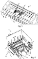
figure 1 shows a first lateral axonometric view of a machine tool according to the present invention comprising four operating heads and an automatic lubrication system comprising a lubricant dispenser, for lubricating the spindles of these operating heads; -
figure 2 shows a front view of the machine tool offigure 1 ; -
figure 3 shows a second axonometric view from above of the machine tool offigure 1 ; -
figure 4 shows an axonometric view from below of a first embodiment of an operating head of a machine tool according to the present invention, comprising a plurality of spindles, respective openings of lubrication ducts associated with the spindles, in which to insert lubricant, and drilling bits coupled to the spindles; -
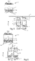
figure 5 shows a side view of a detail of a machine tool according to the present invention during a working phase, in which a machined panel arranged on a working plane defined by two respective supporting elements is shown, a lubricant dispenser in a rest configuration, and an operating head comprising spindles, respective openings of lubrication ducts associated with the spindles and drilling bits coupled to the spindles; -
figure 6 shows a side view of the detail of the machine tool offigure 5 during a first lubrication phase, in which the lubricant dispenser is in an operative configuration; -
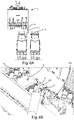
figure 7A shows a side view of the detail of the machine tool offigure 5 , during a second lubrication step, in which the lubricant dispenser occupies an opening of a lubrication duct of a respective spindle; -
figure 7B shows a side perspective view of a detail offigure 7A ; -
figure 8A shows a side view of the detail of the machine tool offigure 5 , during a third lubrication phase, in which the lubricant dispenser delivers lubricant inside the opening of the lubrication duct; -
figure 8B shows a perspective view, from below, of a detail offigure 8A ; and -
figure 9 shows a side view of the detail of the machine tool offigure 5 , during a fourth lubrication phase, in which the lubricant dispenser has finished dispensing lubricant inside the opening of the lubrication duct. - With reference to
figures 1 - 9 , amachine tool 1 can be seen, in particular adrilling machine 1, for machining wooden panels P and the like according to the present invention, comprising - a working
surface 2 on which a panel P is arranged, - four
operating heads 3, movable relative to the panel P for its machining, and - a control unit (not shown), connected to said operating heads 3, to control their movement relative to the working
surface 2. - In particular, in the embodiment shown, the operating heads 3 are movable relative to the working surface.
- The
machine tool 1 in fact comprises - a frame comprising a pair of parallel
longitudinal members 10, which extend in length along a horizontal X-axis, and which are equipped withrespective tracks 100; - four supporting
elements 11', 11" slidingly coupled with saidtracks 100, in which the top surfaces of said supportingelements 11', 11" jointly define the aforementioned workingsurface 2; and - a
lubricant dispenser 5 connected to a support element 11', the function of which will be better illustrated below. - In the embodiment shown there is in fact a first pair of supporting elements 11', and a second pair of supporting
elements 11", spaced from said first pair, in which the supporting elements 11' of said first pair are separated one from the other to form ahousing 12 between them to house thelubricant dispenser 5. - The supporting
elements 11', 11" also comprise respective supportingsurfaces 110, orshelves 110, coplanar with each other, which they define the workingsurface 2. - In other words, the panel P, during use, rests on the four
support surfaces 110 of the supportingelements 11', 11". - Since, as mentioned, these supporting
elements 11', 11" can be moved along thetracks 100, the extension of the workingsurface 2 can be advantageously adjusted based on the different types of panels P to be machined. - However, in alternative embodiments (not shown), the working
surface 2 can be formed by elements other than those described, and can also be fixed. By way of example, only a pair of supporting elements 11' can be present, in particular a pair of fixed supporting elements 11'. Furthermore, themachine tool 1 may not comprise said tracks 100. - As mentioned, four operating
heads 3 are shown infigures 1-4 . However, in one embodiment (not shown), the number of operating heads 3 of themachine tool 1 can be different from four, as there may also be only oneoperating head 3. - Finally, the control unit can be of the programmable type and can comprise or be connected to storage means for memorizing the position of the various elements connected to it.
- The same control unit can also be configured to control the displacements of the supporting
elements 11', 11" along thetracks 100. - The
lubricant dispenser 5 shown infigures 1-9 comprises atank 50 containing lubricant, for example grease, and a dispensingpump 51 in fluid connection with thetank 50. The dispensingpump 51 is configured to deliver lubricant from thetank 50 when operated, particularly when subjected to pressure. Said pressure can be exerted by the operating head, but it is possible to provide that this pressure is exerted by a special device not integral with the operating head. - Other embodiments (not shown) provide for forms of actuation other than the exertion of a pressure by the operating head, such as for example an electric control and/or a pneumatic control. The term "command" can mean both a sensor element, for example a proximity and/or contact sensor, and an actuator element, for example an electric and/or pneumatic actuator.
- The dispensing
pump 51 can be equipped with a suitable valve, in particular a spherical valve, to prevent the undesired leakage of lubricant. - In the particular embodiment shown, the
lubricant dispenser 5 has a substantially vertical development. Specifically, the dispensingpump 51 is a stem arranged along a vertical Z-axis, orthogonal to the horizontal X-axis, for the reasons illustrated below. - As said, the
lubricant dispenser 5 is arranged inside thehousing 12 between the supporting elements 11' and coupled to one of them, thus forming a lubrication station or greasing station for the spindles of the operating heads 3. - Spindle lubrication means the lubrication of the parts of the spindles most subject to wear, such as bearings and/or gears for motion transmission.
- Furthermore, with particular reference to
figures 5-9 , thelubricant dispenser 5 is configured to move along the vertical Z-axis, between a rest configuration, in which it is arranged below the working surface 2 (seefigure 5 ), and an operating configuration (seefigure 6 ), in which at least the dispensingpump 51 protrudes above the workingsurface 2, for the reasons illustrated below. - The movement of the
lubricant dispenser 5 can also take place under the control of said control unit. - In other words, in the embodiment shown, the
lubricant dispenser 5 is associated with the workingsurface 2. - Advantageously, this arrangement of the
lubricant dispenser 5, and in particular the fact that it is associated with the workingsurface 2, allows minimizing the overall dimensions of themachine tool 1 for the reasons illustrated below. - In alternative embodiments (not shown), the
lubricant dispenser 5 can be coupled to different elements of themachine tool 1, for example to alongitudinal member 10 or another part of the frame, or to a further mobile element of themachine tool 1. - Alternatively, the
lubricant dispenser 5 can be arranged in a lubrication area separated from the workingsurface 2. - Furthermore, the coupling between the
lubricant dispenser 5 and themachine tool 1 can be of the removable type, to facilitate the refilling thetank 50. - With particular reference to
figure 4 , an operatinghead 3 of amachine tool 1 according to the present invention comprises a plurality ofspindles 30, on whichdrilling bits 4 can be removably mounted for drilling the panel P arranged on the underlying workingsurface 2. - According to further embodiments (not shown), other working parts for panels P, in addition to the
aforementioned drilling bits 4, may be mounted on thespindles 30; moreover, the number ofspindles 30 can vary, since, in hypothesis, even only onespindle 30 may be present. - The operating
head 3 is configured in such a way as to be able to move, under the action of said control unit, at least along the vertical Z-axis to go down towards the panel P and perform the drilling operations on it provided by the working program in execution. In particular, the operatinghead 3 can move according to the vertical Z-axis and the horizontal X-axis, to allow the machining of different types of panels P. - The operating
head 3 also comprises a plurality oflubrication ducts 31 in fluid connection with the outside through arespective opening 32, for the insertion of lubricant, and with arespective spindle 30, so as to allow the lubrication of thespindle 30 by inserting lubricant through theopening 32. - In particular,
figure 4 shows an operatinghead 3 comprising alubrication duct 31 and arespective opening 32 for eachspindle 30. - These
openings 32 are arranged close to each other, being concentrated onsuitable portions 320 of the operatinghead 3. This allows limiting the movements of the operatinghead 3 during the automatic lubrication of thespindles 30, which will be illustrated below, and, consequently, to reduce the times' machine downtime for the execution of this automatic lubrication. - Furthermore, the
portions 320 in which theopenings 32 are formed are projecting with respect to thespindles 30, to facilitate this automatic lubrication step. - According to further embodiments (not shown), the number of
openings 32 and/or oflubrication ducts 31 can be different from the number of thespindles 30, for example, anopening 32 can be provided, into whichmore lubrication ducts 31 open in their turn in fluid connection with therelative spindles 30. - The
opening 32 can be coupled to the dispensingpump 51 of thelubricant dispenser 5, by means of the method illustrated below. - A further embodiment (not shown) comprises a
lubricant dispenser 5, which can be coupled simultaneously to a plurality of saidopenings 32. In this case, thelubricant dispenser 5 comprises a plurality of dispensing pumps 51 in fluid connection with asingle tank 50, or with a plurality ofrespective tanks 50. - Each
opening 32 can also be provided with a suitable valve to prevent dripping of the lubricant onto the workingsurface 2 and/or onto the panel P to be machined. - With particular reference to
figures 5-9 , an operating mode of themachine tool 1 just described is now illustrated, in which the lubrication of thespindles 30 is carried out in an automated way. - In a working phase of the
machine tool 1 shown infigure 5 , the operatinghead 3 is moving away from the underlying panel P arranged on the workingsurface 2, after having performed the drilling operations on the latter by means of thedrilling bits 4, while thelubricant dispenser 5 is in the respective rest configuration inside thehousing 12, i.e. between the two supporting elements 11'. By way of example, for the execution of the foreseen workings, the panel P can be moved on the working plane, during the work itself, for example along a horizontal axis orthogonal to the X-axis. - Before or after the machining of the panel P, a lubrication step, shown in
figures 6-9 , must be provided. - During a first lubrication step shown in
figure 6 , in which no panel P is present on the workingsurface 2, the control unit arranges the lifting of thelubricant dispenser 5 in the operating configuration, and the vertical alignment, along the vertical Z-axis, between an opening 32 of the operatinghead 3 and the dispensingpump 51. - Since the
lubricant dispenser 5 is arranged in correspondence with the workingsurface 2, the advantage is obtained of limiting the displacements of the operatinghead 3 to carrying out the lubrication operations. This makes it possible to producemachine tools 1 of contained dimensions. - However, as mentioned, in different embodiments, the
lubricant dispenser 5 may not be associated with the workingsurface 2, being for example arranged in a lubrication area separated from it. In this case, the operatinghead 3 and/or thelubricant dispenser 5 will have to perform longer strokes than in the case illustrated above, in order to carry out the lubrication operations. - In a second lubrication step, shown in
figures 7A and 7B , the control unit arranges the lowering of the operatinghead 3 along the vertical Z-axis until contact, i.e. coupling, is achieved between theaforementioned opening 32 and the dispensingpump 51. - In a third lubrication step, shown in
figures 8A and 8B , the control unit commands a further lowering of the operatinghead 3 along the vertical Z-axis, so that the operatinghead 3 activates the dispensingpump 51, in particular by exerting said pressure on the dispensingpump 51 and causing its stem to lower, for the delivery of the lubricant in thelubrication duct 31 connected to saidopening 32 and the consequent lubrication of therespective spindle 30. - In a fourth lubrication step, shown in
figure 9 , the control unit arranges the lifting of the operatinghead 3 along the vertical Z-axis, thus interrupting the passage of the lubricant from the dispensingpump 51 to thelubrication duct 31. - The lubrication steps can therefore be repeated for each
opening 32 present on the operatinghead 3. - In alternative embodiments (not shown), the lubrication steps can take place by keeping the operating head in one position and moving, directly or indirectly, through the control unit, only the
lubricant dispenser 5, or both thelubricant dispenser 5 and the operatinghead 3, in such a way as to obtain in any case the reciprocal coupling between the dispensingpump 51 and anopening 32 of the operatinghead 3. - Furthermore, if only one
opening 32 is present, the operatinghead 3 and/or thelubricant dispenser 5 could be configured, in principle, to move only along the vertical Z-axis, the dispensingpump 51 being arranged in themachine tool 1 to be aligned with theopening 32 along the vertical Z-axis. In summary, an automatic lubrication method of aspindle 30, which can be actuated by a control unit of amachine tool 1 of the type described, may comprise the following steps: - A. moving the operating
head 3 and/or thelubricant dispenser 5, so as to couple, for example bringing the dispensingpump 51 into mutual communication with anopening 32 of the operatinghead 3; and - B. operating the dispensing
pump 51 for the automatic delivery of the lubricant in thelubrication duct 31 through saidopening 32 and the consequent lubrication of therespective spindle 30. - In particular, during step B., the control unit operates the dispensing
pump 51 by means of an electric control, and/or a pneumatic control, and/or the exertion of a pressure. - For example, during said step B., it is possible to command a reciprocal approach between the operating
head 3 and the dispensingpump 51, so that said pressure is exerted on the dispensingpump 51 through the operatinghead 3. - Furthermore, this automatic method can comprise the following substeps of step A.:
- A1. arranging the operating
head 3 with saidopening 32 aligned with the dispensingpump 51, with respect to the vertical Z-axis; and - A2. moving the operating
head 3 with respect to the dispensingpump 51 along the vertical Z-axis, so as to make the dispensingpump 51 to couple with saidopening 32. - The steps A. and B. can be repeated for each
opening 32 connected to thelubrication ducts 31 of the operatinghead 3. - Alternatively, it is possible to provide that step A. comprises the simultaneous coupling of a plurality of dispensing pumps 51 (not shown) of a
lubricant dispenser 5 to a plurality ofopenings 32, preferably to allopenings 32 connected to thelubrication ducts 31 of the operating head. In this way, it is possible to carry out the simultaneous dispensing of the lubricant in the plurality oflubrication ducts 31 of the operatinghead 3 through said plurality ofopenings 32 and resulting in the simultaneous lubrication of said plurality ofspindles 30. - In the foregoing the preferred embodiments and variants of the present invention have been described and have been suggested, but it is understood that those skilled in the art will be able to make modifications and changes without thereby departing from the relative scope of protection, as defined by the attached claims.
- The
machine tool 1 and the automatic lubrication method described make it possible to automate the lubrication of thespindles 30, advantageously reducing the machine downtime and the related maintenance costs. - Furthermore, since man-machine interactions are reduced, the
machine tool 1 is advantageously safer than the machines of the known art. - Furthermore, thanks to the particular arrangement of the
lubricant dispenser 5 described, themachine tool 1 does not have larger dimensions than the machines of the prior art, which provide for the manual lubrication of thespindles 30. - Furthermore, the
machine tool 1 described can be advantageously adapted to different types of operating heads 3 with different arrangements of thespindles 30 and of therelative openings 32, simply by reprogramming the control unit. - The present invention has been described for illustrative but not limitative purposes, according to its preferred embodiments, but it is to be understood that modifications and/or changes can be introduced by those skilled in the art without departing from the relevant scope as defined in the enclosed claims.
Claims (15)
- Machine tool (1), in particular for machining elements to be machined (P) such as wooden panels and similar, comprising:a working surface (2), for receiving an element to be machined (P);at least one operative head (3), movable relative to said element to be machined (P), and comprising
at least one spindle (30), able to be coupled, in use, to a respective machining member (4), for machining said element to be machined (P), andat least one lubricating conduit (31) in fluid connection with at least one opening (32), for introducing a lubricant, and with said at least one spindle (30);a lubricant dispenser (5), able to be coupled to said at least one opening (32), said lubricant dispenser (5) being configured for dispensing, when activated, said lubricant; anda control unit, for controlling the movement of said operative head (3) and/or of said lubricant dispenser (5),wherein said control unit is configured to command at least one mutual movement between said operative head (3) and said lubricant dispenser (5), to couple said lubricant dispenser (5) to said at least one opening (32), and to activate said lubricant dispenser (5) such that said lubricant dispenser (5) supplies said lubricant into said at least one lubricating conduit (31) through said at least one opening (32), to lubricate said at least one spindle (30). - Machine tool (1) according to claim 1, characterized in that said lubricant dispenser (5) is configured to be activated by means of an electric command, and/or a pneumatic command, and/or by exercising a pressure.
- Machine tool (1) according to any one of the previous claims, characterized in that said lubricant dispenser (5) is configured for being activated by exercising a pressure, and in that said control unit is configured to command said at least one mutual movement between said operative head (3) and said lubricant dispenser (5) such that said operative head (3) exercises said pressure on the lubricant dispenser (5).
- Machine tool (1) according to any one of claims 2 or 3, characterized in that said lubricant dispenser (5) comprises a tank (50) for containing said lubricant and a dispensing pump (51) in fluid connection with said tank (50); said dispensing pump (51) being configured for dispensing said lubricant from said tank (50) when subjected to said predetermined pressure.
- Machine tool (1) according to any one of the previous claims, characterized in thatsaid operative head (3) is movable along at least one axis (Z), preferably a vertical axis (Z), and in thatsaid lubricant dispenser (5) is placed on said axis (Z),wherein said control unit is configured for moving said operative head (3) at least along said axis (Z).
- Machine tool (1) according to any one of the previous claims, characterized in that said lubricant dispenser (5) is removable with respect to said machine tool (1).
- Machine tool (1) according to any one of the previous claims, characterized in that said lubricant dispenser (5) is connectable with said working surface (2).
- Machine tool (1) according to any one of the previous claims, characterized in that said lubricant dispenser (5) is movable between a resting configuration, where said lubricant dispenser (5) is completely placed below said working surface (2), and an operative configuration, where said lubricant dispenser (5) protrudes at least partially above said working surface (2).
- Machine tool (1) according to any one of the previous claims, characterized in that it comprises at least one pair of supporting elements (11), defining said working surface (2) and placed apart from each other; wherein said lubricant dispenser (5) is placed between said supporting elements (11).
- Machine tool (1) according to any one of the previous claims, characterizedin that said operative head (3) comprises a plurality of spindles (30), in that a lubricating conduit (31) is provided, which is associated with each spindle (30), andin that a plurality of openings (32), preferably a respective opening (32) for each lubricating conduit (31), is provided.
- Machine tool (1) according to the previous claim, characterized in that said lubricant dispenser (5) is able to be simultaneously coupled to a plurality of said openings (32), in particular to all said openings (32).
- Method to automatically lubricate a spindle (30) of a machine tool (1) according to any one of the previous claims, comprising the following steps which are executable by said control unit:A. moving said operative head (3) and/or said lubricant dispenser (5) such as to couple said lubricant dispenser (5) with said at least one opening (32); andB. activating said lubricant dispenser (5) to automatically supply said lubricant into said at least one lubricating conduit (31) through said at least one opening (32) and consequently lubricate said at least one spindle (30).
- Method according to the previous claim, wherein said step B. is executed by means of an electric command, and/or a pneumatic command, and/or by exercising a pressure.
- Method according to any one of claims 12-13, wherein said operative head (3) comprises a plurality of spindles (30), a plurality of lubricating conduits (31) in fluid communication with said plurality of spindles (30), and a plurality of openings (32) in which said plurality of lubricating conduits (31) ends; and wherein said steps A. and B. are repeated for each opening of said plurality of openings (32).
- Method according to any one of claims 12-13 wherein said operative head (3) comprises a plurality of spindles (30), a plurality of lubricating conduits (31) in fluid communication with said plurality of spindles (30), and a plurality of openings (32) in which said plurality of lubricating conduits (31) ends; and wherein said step A. comprises simultaneously coupling said lubricant dispenser (5) with a plurality of said openings (32), in particular with all said openings (32).
Applications Claiming Priority (1)
| Application Number | Priority Date | Filing Date | Title |
|---|---|---|---|
| IT102020000028340A IT202000028340A1 (en) | 2020-11-25 | 2020-11-25 | MACHINE TOOL WITH AUTOMATIC LUBRICATION SYSTEM AND RELATED LUBRICATION METHOD. |
Publications (2)
| Publication Number | Publication Date |
|---|---|
| EP4005730A1 true EP4005730A1 (en) | 2022-06-01 |
| EP4005730B1 EP4005730B1 (en) | 2025-10-08 |
Family
ID=74557166
Family Applications (1)
| Application Number | Title | Priority Date | Filing Date |
|---|---|---|---|
| EP21209755.4A Active EP4005730B1 (en) | 2020-11-25 | 2021-11-23 | Machine tool with an automatic lubricating system and related lubricating method |
Country Status (2)
| Country | Link |
|---|---|
| EP (1) | EP4005730B1 (en) |
| IT (1) | IT202000028340A1 (en) |
Cited By (1)
| Publication number | Priority date | Publication date | Assignee | Title |
|---|---|---|---|---|
| CN118386337A (en) * | 2024-06-27 | 2024-07-26 | 江苏盛阳消防门业有限公司 | A drilling device and drilling process for producing fire-fighting wooden doors |
Citations (4)
| Publication number | Priority date | Publication date | Assignee | Title |
|---|---|---|---|---|
| DE19607176A1 (en) * | 1996-02-27 | 1997-08-28 | Axa Entwicklung Maschinenbau | Numerically-controlled machine tool |
| ES2334751A1 (en) * | 2009-07-01 | 2010-03-15 | Jordi Galan Llongueras | System of lubrication of rings for retorceror machines (Machine-translation by Google Translate, not legally binding) |
| US20200114482A1 (en) * | 2018-10-15 | 2020-04-16 | Okuma Corporation | Cooling liquid feeder |
| US20200230767A1 (en) * | 2019-01-18 | 2020-07-23 | Sichuan University | External cooling mql manipulators and machine tools and lubrication method using machine tools |
Family Cites Families (2)
| Publication number | Priority date | Publication date | Assignee | Title |
|---|---|---|---|---|
| JP3521389B2 (en) * | 2001-08-10 | 2004-04-19 | ホーコス株式会社 | Multi-axis machine tool and method of optimizing lubricant mist flow rate of each spindle in multi-axis machine tool |
| EP2266751A1 (en) * | 2003-10-14 | 2010-12-29 | Gühring, Jörg | Shaft tool and associated coolant/lubricant feeding point |
-
2020
- 2020-11-25 IT IT102020000028340A patent/IT202000028340A1/en unknown
-
2021
- 2021-11-23 EP EP21209755.4A patent/EP4005730B1/en active Active
Patent Citations (4)
| Publication number | Priority date | Publication date | Assignee | Title |
|---|---|---|---|---|
| DE19607176A1 (en) * | 1996-02-27 | 1997-08-28 | Axa Entwicklung Maschinenbau | Numerically-controlled machine tool |
| ES2334751A1 (en) * | 2009-07-01 | 2010-03-15 | Jordi Galan Llongueras | System of lubrication of rings for retorceror machines (Machine-translation by Google Translate, not legally binding) |
| US20200114482A1 (en) * | 2018-10-15 | 2020-04-16 | Okuma Corporation | Cooling liquid feeder |
| US20200230767A1 (en) * | 2019-01-18 | 2020-07-23 | Sichuan University | External cooling mql manipulators and machine tools and lubrication method using machine tools |
Cited By (1)
| Publication number | Priority date | Publication date | Assignee | Title |
|---|---|---|---|---|
| CN118386337A (en) * | 2024-06-27 | 2024-07-26 | 江苏盛阳消防门业有限公司 | A drilling device and drilling process for producing fire-fighting wooden doors |
Also Published As
| Publication number | Publication date |
|---|---|
| IT202000028340A1 (en) | 2022-05-25 |
| EP4005730B1 (en) | 2025-10-08 |
Similar Documents
| Publication | Publication Date | Title |
|---|---|---|
| EP4005730B1 (en) | Machine tool with an automatic lubricating system and related lubricating method | |
| JP6691353B2 (en) | Lubricant injection system | |
| CN103212655B (en) | Wire cutting machine for coils | |
| CN105500086A (en) | Drilling machine and tool changing method thereof | |
| CN118582648B (en) | A needle bearing grease injection mechanism and automatic assembly device | |
| JP2010537836A (en) | Machining apparatus and method | |
| KR200484404Y1 (en) | Object removed device of the work piece using a centrifugal force | |
| US20100209220A1 (en) | Rotary actuator position sensor | |
| KR102595029B1 (en) | Apparatus and method for pressing solid lubricants into bearing | |
| CN111438530A (en) | Carousel formula bearing frame drilling tapping device | |
| CN205869955U (en) | Automobile starter isolator automatic assembly lathe | |
| EP3722482B1 (en) | Manifold with a plurality of fluid outlets and a delivery head | |
| EP3666725B1 (en) | Station for dispensing one or more operating fluids to a motor vehicle being assembled | |
| JP2015178169A (en) | Machine Tools | |
| DE19643960A1 (en) | Sewing machine lubrication | |
| CN2719424Y (en) | Finished bearing rotary cleaning machine | |
| KR20230053103A (en) | coolant supply unit of nc machine | |
| CN209997834U (en) | Sleeve oil sprayer | |
| JP3304583B2 (en) | Lubrication device for punch holder hole and punch holder peripheral surface | |
| US2896394A (en) | Lubricating system for fly frames | |
| US2209939A (en) | Automatically controlled gravity oiler | |
| JP2014058025A (en) | Method for controlling lubricant supply device | |
| CN212268721U (en) | Working line body matching and picking device | |
| KR101512830B1 (en) | Forming machines for assembling hole portion in connecting piece | |
| KR102692124B1 (en) | Assembly apparatus of balance shaft unit for engine and operating method thereof |
Legal Events
| Date | Code | Title | Description |
|---|---|---|---|
| PUAI | Public reference made under article 153(3) epc to a published international application that has entered the european phase |
Free format text: ORIGINAL CODE: 0009012 |
|
| STAA | Information on the status of an ep patent application or granted ep patent |
Free format text: STATUS: THE APPLICATION HAS BEEN PUBLISHED |
|
| AK | Designated contracting states |
Kind code of ref document: A1 Designated state(s): AL AT BE BG CH CY CZ DE DK EE ES FI FR GB GR HR HU IE IS IT LI LT LU LV MC MK MT NL NO PL PT RO RS SE SI SK SM TR |
|
| STAA | Information on the status of an ep patent application or granted ep patent |
Free format text: STATUS: REQUEST FOR EXAMINATION WAS MADE |
|
| 17P | Request for examination filed |
Effective date: 20221130 |
|
| RBV | Designated contracting states (corrected) |
Designated state(s): AL AT BE BG CH CY CZ DE DK EE ES FI FR GB GR HR HU IE IS IT LI LT LU LV MC MK MT NL NO PL PT RO RS SE SI SK SM TR |
|
| P01 | Opt-out of the competence of the unified patent court (upc) registered |
Effective date: 20230518 |
|
| STAA | Information on the status of an ep patent application or granted ep patent |
Free format text: STATUS: EXAMINATION IS IN PROGRESS |
|
| 17Q | First examination report despatched |
Effective date: 20241008 |
|
| GRAP | Despatch of communication of intention to grant a patent |
Free format text: ORIGINAL CODE: EPIDOSNIGR1 |
|
| STAA | Information on the status of an ep patent application or granted ep patent |
Free format text: STATUS: GRANT OF PATENT IS INTENDED |
|
| INTG | Intention to grant announced |
Effective date: 20250519 |
|
| GRAS | Grant fee paid |
Free format text: ORIGINAL CODE: EPIDOSNIGR3 |
|
| GRAA | (expected) grant |
Free format text: ORIGINAL CODE: 0009210 |
|
| STAA | Information on the status of an ep patent application or granted ep patent |
Free format text: STATUS: THE PATENT HAS BEEN GRANTED |
|
| AK | Designated contracting states |
Kind code of ref document: B1 Designated state(s): AL AT BE BG CH CY CZ DE DK EE ES FI FR GB GR HR HU IE IS IT LI LT LU LV MC MK MT NL NO PL PT RO RS SE SI SK SM TR |
|
| REG | Reference to a national code |
Ref country code: GB Ref legal event code: FG4D Ref country code: CH Ref legal event code: F10 Free format text: ST27 STATUS EVENT CODE: U-0-0-F10-F00 (AS PROVIDED BY THE NATIONAL OFFICE) Effective date: 20251008 |
|
| REG | Reference to a national code |
Ref country code: DE Ref legal event code: R096 Ref document number: 602021039981 Country of ref document: DE |
|
| REG | Reference to a national code |
Ref country code: IE Ref legal event code: FG4D |
|
| PGFP | Annual fee paid to national office [announced via postgrant information from national office to epo] |
Ref country code: DE Payment date: 20251028 Year of fee payment: 5 |
|
| PGFP | Annual fee paid to national office [announced via postgrant information from national office to epo] |
Ref country code: AT Payment date: 20260113 Year of fee payment: 5 |
|
| PGFP | Annual fee paid to national office [announced via postgrant information from national office to epo] |
Ref country code: IT Payment date: 20251211 Year of fee payment: 5 |
|
| REG | Reference to a national code |
Ref country code: NL Ref legal event code: MP Effective date: 20251008 |
|
| PG25 | Lapsed in a contracting state [announced via postgrant information from national office to epo] |
Ref country code: NL Free format text: LAPSE BECAUSE OF FAILURE TO SUBMIT A TRANSLATION OF THE DESCRIPTION OR TO PAY THE FEE WITHIN THE PRESCRIBED TIME-LIMIT Effective date: 20251008 |
|
| PG25 | Lapsed in a contracting state [announced via postgrant information from national office to epo] |
Ref country code: ES Free format text: LAPSE BECAUSE OF FAILURE TO SUBMIT A TRANSLATION OF THE DESCRIPTION OR TO PAY THE FEE WITHIN THE PRESCRIBED TIME-LIMIT Effective date: 20251008 |
|
| REG | Reference to a national code |
Ref country code: LT Ref legal event code: MG9D |
|
| PG25 | Lapsed in a contracting state [announced via postgrant information from national office to epo] |
Ref country code: NO Free format text: LAPSE BECAUSE OF FAILURE TO SUBMIT A TRANSLATION OF THE DESCRIPTION OR TO PAY THE FEE WITHIN THE PRESCRIBED TIME-LIMIT Effective date: 20260108 |
|
| PG25 | Lapsed in a contracting state [announced via postgrant information from national office to epo] |
Ref country code: HR Free format text: LAPSE BECAUSE OF FAILURE TO SUBMIT A TRANSLATION OF THE DESCRIPTION OR TO PAY THE FEE WITHIN THE PRESCRIBED TIME-LIMIT Effective date: 20251008 Ref country code: FI Free format text: LAPSE BECAUSE OF FAILURE TO SUBMIT A TRANSLATION OF THE DESCRIPTION OR TO PAY THE FEE WITHIN THE PRESCRIBED TIME-LIMIT Effective date: 20251008 |
|
| PG25 | Lapsed in a contracting state [announced via postgrant information from national office to epo] |
Ref country code: RS Free format text: LAPSE BECAUSE OF FAILURE TO SUBMIT A TRANSLATION OF THE DESCRIPTION OR TO PAY THE FEE WITHIN THE PRESCRIBED TIME-LIMIT Effective date: 20260108 |
|
| PG25 | Lapsed in a contracting state [announced via postgrant information from national office to epo] |
Ref country code: IS Free format text: LAPSE BECAUSE OF FAILURE TO SUBMIT A TRANSLATION OF THE DESCRIPTION OR TO PAY THE FEE WITHIN THE PRESCRIBED TIME-LIMIT Effective date: 20260208 |
|
| PG25 | Lapsed in a contracting state [announced via postgrant information from national office to epo] |
Ref country code: PT Free format text: LAPSE BECAUSE OF FAILURE TO SUBMIT A TRANSLATION OF THE DESCRIPTION OR TO PAY THE FEE WITHIN THE PRESCRIBED TIME-LIMIT Effective date: 20260209 |
|
| PG25 | Lapsed in a contracting state [announced via postgrant information from national office to epo] |
Ref country code: PL Free format text: LAPSE BECAUSE OF FAILURE TO SUBMIT A TRANSLATION OF THE DESCRIPTION OR TO PAY THE FEE WITHIN THE PRESCRIBED TIME-LIMIT Effective date: 20251008 |
|
| PG25 | Lapsed in a contracting state [announced via postgrant information from national office to epo] |
Ref country code: LV Free format text: LAPSE BECAUSE OF FAILURE TO SUBMIT A TRANSLATION OF THE DESCRIPTION OR TO PAY THE FEE WITHIN THE PRESCRIBED TIME-LIMIT Effective date: 20251008 |
|
| PG25 | Lapsed in a contracting state [announced via postgrant information from national office to epo] |
Ref country code: BG Free format text: LAPSE BECAUSE OF FAILURE TO SUBMIT A TRANSLATION OF THE DESCRIPTION OR TO PAY THE FEE WITHIN THE PRESCRIBED TIME-LIMIT Effective date: 20251008 |