EP4005463A1 - Endoscope shape display control device, operation method for endoscope shape display control device, and operation program for endoscope shape display control device - Google Patents
Endoscope shape display control device, operation method for endoscope shape display control device, and operation program for endoscope shape display control device Download PDFInfo
- Publication number
- EP4005463A1 EP4005463A1 EP20844040.4A EP20844040A EP4005463A1 EP 4005463 A1 EP4005463 A1 EP 4005463A1 EP 20844040 A EP20844040 A EP 20844040A EP 4005463 A1 EP4005463 A1 EP 4005463A1
- Authority
- EP
- European Patent Office
- Prior art keywords
- insertion part
- magnetic field
- endoscope
- shape
- shape display
- Prior art date
- Legal status (The legal status is an assumption and is not a legal conclusion. Google has not performed a legal analysis and makes no representation as to the accuracy of the status listed.)
- Granted
Links
Images








Classifications
-
- A—HUMAN NECESSITIES
- A61—MEDICAL OR VETERINARY SCIENCE; HYGIENE
- A61B—DIAGNOSIS; SURGERY; IDENTIFICATION
- A61B1/00—Instruments for performing medical examinations of the interior of cavities or tubes of the body by visual or photographical inspection, e.g. endoscopes; Illuminating arrangements therefor
- A61B1/00002—Operational features of endoscopes
- A61B1/00004—Operational features of endoscopes characterised by electronic signal processing
- A61B1/00009—Operational features of endoscopes characterised by electronic signal processing of image signals during a use of endoscope
-
- A—HUMAN NECESSITIES
- A61—MEDICAL OR VETERINARY SCIENCE; HYGIENE
- A61B—DIAGNOSIS; SURGERY; IDENTIFICATION
- A61B1/00—Instruments for performing medical examinations of the interior of cavities or tubes of the body by visual or photographical inspection, e.g. endoscopes; Illuminating arrangements therefor
- A61B1/00147—Holding or positioning arrangements
- A61B1/00158—Holding or positioning arrangements using magnetic field
-
- A—HUMAN NECESSITIES
- A61—MEDICAL OR VETERINARY SCIENCE; HYGIENE
- A61B—DIAGNOSIS; SURGERY; IDENTIFICATION
- A61B1/00—Instruments for performing medical examinations of the interior of cavities or tubes of the body by visual or photographical inspection, e.g. endoscopes; Illuminating arrangements therefor
- A61B1/005—Flexible endoscopes
- A61B1/009—Flexible endoscopes with bending or curvature detection of the insertion part
-
- A—HUMAN NECESSITIES
- A61—MEDICAL OR VETERINARY SCIENCE; HYGIENE
- A61B—DIAGNOSIS; SURGERY; IDENTIFICATION
- A61B1/00—Instruments for performing medical examinations of the interior of cavities or tubes of the body by visual or photographical inspection, e.g. endoscopes; Illuminating arrangements therefor
- A61B1/04—Instruments for performing medical examinations of the interior of cavities or tubes of the body by visual or photographical inspection, e.g. endoscopes; Illuminating arrangements therefor combined with photographic or television appliances
-
- A—HUMAN NECESSITIES
- A61—MEDICAL OR VETERINARY SCIENCE; HYGIENE
- A61B—DIAGNOSIS; SURGERY; IDENTIFICATION
- A61B1/00—Instruments for performing medical examinations of the interior of cavities or tubes of the body by visual or photographical inspection, e.g. endoscopes; Illuminating arrangements therefor
- A61B1/04—Instruments for performing medical examinations of the interior of cavities or tubes of the body by visual or photographical inspection, e.g. endoscopes; Illuminating arrangements therefor combined with photographic or television appliances
- A61B1/045—Control thereof
-
- A—HUMAN NECESSITIES
- A61—MEDICAL OR VETERINARY SCIENCE; HYGIENE
- A61B—DIAGNOSIS; SURGERY; IDENTIFICATION
- A61B1/00—Instruments for performing medical examinations of the interior of cavities or tubes of the body by visual or photographical inspection, e.g. endoscopes; Illuminating arrangements therefor
- A61B1/06—Instruments for performing medical examinations of the interior of cavities or tubes of the body by visual or photographical inspection, e.g. endoscopes; Illuminating arrangements therefor with illuminating arrangements
- A61B1/0661—Endoscope light sources
- A61B1/0684—Endoscope light sources using light emitting diodes [LED]
-
- A—HUMAN NECESSITIES
- A61—MEDICAL OR VETERINARY SCIENCE; HYGIENE
- A61B—DIAGNOSIS; SURGERY; IDENTIFICATION
- A61B1/00—Instruments for performing medical examinations of the interior of cavities or tubes of the body by visual or photographical inspection, e.g. endoscopes; Illuminating arrangements therefor
- A61B1/31—Instruments for performing medical examinations of the interior of cavities or tubes of the body by visual or photographical inspection, e.g. endoscopes; Illuminating arrangements therefor for the rectum, e.g. proctoscopes, sigmoidoscopes, colonoscopes
-
- A—HUMAN NECESSITIES
- A61—MEDICAL OR VETERINARY SCIENCE; HYGIENE
- A61B—DIAGNOSIS; SURGERY; IDENTIFICATION
- A61B1/00—Instruments for performing medical examinations of the interior of cavities or tubes of the body by visual or photographical inspection, e.g. endoscopes; Illuminating arrangements therefor
- A61B1/005—Flexible endoscopes
- A61B1/0051—Flexible endoscopes with controlled bending of insertion part
Definitions
- the present disclosure relates to an endoscope shape display control device, an operation method of an endoscope shape display control device, and an operation program of an endoscope shape display control device.
- An endoscope that observes a lower digestive tract, such as the large intestine, is known.
- the lower digestive tract is intricately bent, unlike an upper digestive tract, such as an esophagus, which extends relatively linearly. Therefore, the endoscope, which is inserted into the lower digestive tract of a subject, such as a patient, an insertion part of the endoscope is also intricately bent.
- an endoscope shape detection device that detects the shape of the insertion part of the endoscope in the subject (for example, see JP2004-551A ) is known.
- the endoscope shape detection device disclosed in JP2004-551A has a function of acquiring information for imaging the shape of the insertion part in the subject by using magnetism and imaging the shape of the insertion part based on the acquired information.
- a plurality of magnetic field generation elements are disposed at intervals in the insertion part of the endoscope.
- the endoscope shape detection device detects a magnetic field generated by each magnetic field generation element in the insertion part by a magnetic field detection element disposed outside the subject.
- the endoscope shape detection device disclosed in JP2004-551A uses information on the intensity of the magnetic field of each magnetic field generation element as the information for imaging the shape of the insertion part to generate an image showing the shape of the insertion part. Further, the generated image is displayed on a monitor and presented to a user, such as an operator (for example, a doctor).
- An imaging procedure in the endoscope shape detection device of JP2004-55 1A is performed as follows, for example.
- the endoscope shape detection device disclosed in JP2004-551A specifies the position of each part of the insertion part to generate a three-dimension model of the insertion part based on the information for imaging the shape of the insertion part (for example, the information on the intensity of the magnetic field described above).
- a rendering process is performed on the three-dimension model of the insertion part to generate a two-dimension image to be displayed on the monitor.
- the two-dimension image is an image showing the shape of the insertion part as viewed from one viewpoint in which the three-dimension model of the insertion part can be optionally set, and in the following, is referred to as a shape display image.
- JP2004-551A discloses that a shade line process or a hidden surface process is performed in a case of the rendering process in order to express front and rear of the intersection portions.
- the insertion part of the endoscope may be displayed in a thin line shape in the shape display image. Therefore, there is a problem that it is difficult for the user to instantaneously determine the front and rear of the intersection portion even in a case in which the shade line process or the hidden surface process is performed on the intersection portion.
- the technology of the present disclosure is to provide an endoscope shape display control device, an operation method of an endoscope shape display control device, and an operation program of the endoscope shape display control device capable of displaying a shape display image in which an overlapping condition of an insertion part is easily visually recognized in the shape display image in which a shape of the insertion part of an endoscope in a state of being inserted into a subject is displayed.
- An aspect of the present disclosure relates to an endoscope shape display control device comprising at least one processor, in which the processor acquires information for imaging a shape of an insertion part of an endoscope inserted in a subject, and displays, in a case of generating a shape display image in which the shape of the insertion part is displayed based on the acquired information, the insertion part with a pattern added on a surface thereof in the shape display image.
- the pattern may be added to an entire region of the insertion part displayed in the shape display image.
- the pattern may be a gradation in which a color is changed continuously or stepwise from one of a distal end side or a proximal end side of the insertion part to the other thereof.
- the gradation may be changed from green to blue.
- the pattern may be a stripe pattern.
- the pattern may be a wire frame pattern.
- the processor may perform a shading process on the insertion part in addition to the pattern.
- the information for imaging the shape of the insertion part may be information based on magnetic field measurement data obtained by using a plurality of magnetic field generation elements or a plurality of magnetic field detection elements provided in the insertion part.
- Another aspect of the present disclosure relates to an operation method of an endoscope shape display control device, the method comprising an information acquisition step of acquiring information for imaging a shape of an insertion part of an endoscope inserted in a subject, and an image generation step of generating a shape display image in which the shape of the insertion part is displayed based on the acquired information and displaying the insertion part with a pattern added on a surface thereof in the shape display image.
- Still another aspect of the present disclosure relates to an operation program of an endoscope shape display control device, the program causing a computer to function as an information acquisition unit that acquires information for imaging a shape of an insertion part of an endoscope inserted in a subject, and an image generation unit that generates a shape display image in which the shape of the insertion part is displayed based on the acquired information, the image generation unit displaying the insertion part with a pattern added on a surface thereof in the shape display image.
- an endoscope shape display control device capable of displaying a shape display image in which an overlapping condition of an insertion part is easily visually recognized in the shape display image in which a shape of the insertion part of an endoscope in a state of being inserted into a subject is displayed.
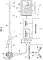
- Fig. 1 is a schematic view showing an overall configuration of an endoscope system 9 comprising an endoscope shape display control device according to the technology of the present disclosure.
- the endoscope system 9 comprises an endoscope 10, a light source device 11, a navigation device 12, a magnetic field generator 13, a processor device 14, and a monitor 15.
- the endoscope system 9 is used for an endoscopic examination in a body of a subject H, such as a patient.
- the subject H is an example of a subject.
- the endoscope 10 is, for example, an endoscope inserted into the digestive tract, such as the large intestine, and is a soft endoscope having flexibility.
- the endoscope 10 has an insertion part 17 to be inserted into the digestive tract, an operating part 18 connected sequentially to a proximal end side of the insertion part 17 and gripped by an operator to perform various operations, and a universal cord 19 connected sequentially to the operating part 18.
- the endoscopic examination is performed, for example, in a state in which the subject H lies on an upper surface 16A of a bed 16.
- the insertion part 17 of the endoscope 10 is inserted into the digestive tract from an anus by an operator OP who is the doctor.
- the light source device 11 supplies illumination light that illuminates an inside of the large intestine, which is an observation site, to the endoscope 10.
- the processor device 14 generates an observation image 41 by processing an image captured by the endoscope 10.
- the observation image 41 is displayed on the monitor 15.
- the operator OP proceeds with the endoscopic examination while confirming the observation image 41.
- the observation image 41 displayed on the monitor 15 is basically a motion picture, but it is also possible to display a still picture as the observation image 41 as needed.
- the endoscope system 9 has a navigation function of navigating technique, such as an insertion operation of the endoscope 10 performed by the operator OP.
- the navigation means supporting the technique of the endoscope 10 of the operator OP by presenting an insertion state including the position and the shape of the insertion part 17 of the endoscope 10 in the body of the subject H to the operator OP.
- the navigation function the insertion state of the insertion part 17 is detected using a magnetic field MF and the detected insertion state is presented.
- the navigation function is realized by the navigation device 12, the magnetic field generator 13, and a magnetic field measurement device in the endoscope 10 described below.
- the magnetic field generator 13 generates the magnetic field MF
- the magnetic field generator 13 is attached to, for example, a stand and is disposed beside the bed 16 on which the subject H lies. In addition, the magnetic field generator 13 is disposed within a range in which the generated magnetic field MF reaches the body of the subject H.
- the magnetic field measurement device in the endoscope 10 detects the magnetic field MF generated by the magnetic field generator 13 and measures the intensity of the detected magnetic field MF.
- the navigation device 12 detects the insertion state of the insertion part 17 by deriving a relative position between the magnetic field generator 13 and the insertion part 17 based on a magnetic field measurement result by the magnetic field measurement device.
- the processor device 14 generates a shape display image 42, which shows the insertion state detected by the navigation device 12.
- the monitor 15 displays the observation image 41 and the shape display image 42. Note that the monitor 15 that displays the observation image 41 and the shape display image 42 may be provided separately.
- the insertion part 17 is a tubular portion having a small diameter and a long length, and is configured by a soft part 21, a bendable part 22, and a distal end part 23, which are connected sequentially from the proximal end side to the distal end side.
- the soft part 21 has flexibility.
- the bendable part 22 is a part that can be bent by the operation of the operating part 18.
- An imaging apparatus 48 (see Fig. 3 ) and the like are disposed at the distal end part 23.
- an illumination window 46 see Fig. 3
- an observation window 47 see Fig.
- a treatment tool outlet for a treatment tool to protrude
- a cleaning nozzle for cleaning the observation window 47 by injecting gas and water into the observation window 47 are provided on a distal end surface of the distal end part 23.
- Alight guide 33, a signal cable 32, an operation wire (not shown), and a pipe line for inserting the treatment tool (not shown) are provided in the insertion part 17.
- the light guide 33 extends from the universal cord 19 and guides the illumination light supplied from the light source device 11 to the illumination window 46 at the distal end part 23.
- the signal cable 32 is used for power supply to the imaging apparatus 48 in addition to communication of an image signal from the imaging apparatus 48 and a control signal for controlling the imaging apparatus 48.
- the signal cable 32 also extends from the universal cord 19 and is arranged to the distal end part 23.
- the operation wire is a wire for operating the bendable part 22, and is arranged from the operating part 18 to the bendable part 22.
- the pipe line for inserting the treatment tool is a pipe line for inserting the treatment tool (not shown), such as forcep, and is arranged from the operating part 18 to the distal end part 23.
- a fluid tube for air/water supply is provided in the insertion part 17. The fluid tube supplies the distal end part 23 with gas and water for cleaning the observation window 47.
- a plurality of detection coils 25 are provided from the soft part 21 to the distal end part 23 at preset intervals.
- Each detection coil 25 corresponds to a magnetic field detection element which detects the magnetic field MF
- Each detection coil 25 is affected by the magnetic field MF generated from the magnetic field generator 13, so that an induced electromotive force is generated by an operation of electromagnetic induction, and an induced current is generated by the induced electromotive force.
- a value of the induced current generated from each detection coil 25 represents the intensity of the magnetic field MF detected by each detection coil 25, which is the magnetic field measurement result. That is, the magnetic field measurement result refers to a value depending on the magnitude of the induced current, which represents the intensity of the magnetic field MF.
- the operating part 18 is provided with various operation members operated by the operator. Specifically, the operating part 18 is provided with two types of bending operation knobs 27, an air/water supply button 28, and a suction button 29. Each of the two types of bending operation knobs 27 is connected to the operation wire, and is used for a right-left bending operation and an up-down bending operation of the bendable part 22. In addition, the operating part 18 is provided with a treatment tool inlet port 31 which is an inlet of the pipe line for inserting the treatment tool.
- the universal cord 19 is a connection cord that connects the endoscope 10 to the light source device 11.
- the universal cord 19 encompasses the signal cable 32, the light guide 33, and the fluid tube (not shown).
- a connector 34 connected to the light source device 11 is provided at an end part of the universal cord 19.
- the light source device 11 By connecting the connector 34 to the light source device 11, the light source device 11 supplies the power, the control signal, the illumination light, the gas, and the water necessary for operating the endoscope 10 to the endoscope 10.
- the image signal of the observation site acquired by the imaging apparatus 48 (see Fig. 2 ) of the distal end part 23 and the magnetic field measurement result based on a detection signal of each detection coil 25 are transmitted from the endoscope 10 to the light source device 11.
- the connector 34 is not electrically connected to the light source device 11 by wire using a metal signal line or the like, and instead, the connector 34 and the light source device 11 are connected to each other so as to be capable of optical communication (for example, non-contact type communication).
- the connector 34 transmits and receives the control signal exchanged between the endoscope 10 and the light source device 11 and transmits the image signal and the magnetic field measurement result from the endoscope 10 to the light source device 11 by optical communication.
- the connector 34 is provided with a laser diode (hereinafter, referred to as LD) 36 connected to the signal cable 32.
- LD laser diode
- the LD 36 is used for transmitting a large amount of data from the endoscope 10 to the light source device 11, specifically, transmitting the image signal and the magnetic field measurement result.
- the LD 36 transmits the image signal and the magnetic field measurement result, which has been originally in a form of the electric signal, in a form of an optical signal to a photodiode (hereinafter, referred to as PD) 37 provided in the light source device 11.
- PD photodiode
- both the connector 34 and the light source device 11 are provided with a light transmission and reception unit that converts a small amount of the control signal exchanged between the endoscope 10 and the light source device 11 into the optical signal and transmits and receives the converted optical signal.
- the connector 34 is provided with a power reception unit (not shown) that receives the power by wireless power supply from a power feed unit (not shown) of the light source device 11.
- the light guide 33 in the connector 34 is inserted into the light source device 11.
- the fluid tube (not shown) in the connector 34 is connected to an air/water supply device (not shown) via the light source device 11.
- the light source device 11 and the air/water supply device supply the illumination light, the gas, and the water to the endoscope 10, respectively.
- the light source device 11 supplies the illumination light to the light guide 33 of the endoscope 10 via the connector 34, and supplies the gas and the water supplied from the air/water supply device (not shown) to the fluid tube (not shown) of the endoscope 10.
- the light source device 11 receives the optical signal transmitted from the LD 36 by the PD 37, converts the received optical signal into the original image signal, which is the electric signal, and the magnetic field measurement result, and then outputs the converted image signal and the magnetic field measurement result to the navigation device 12.
- the navigation device 12 outputs the image signal for generating the observation image 41 input from the light source device 11 to the processor device 14.
- the navigation device 12 controls the drive of the magnetic field generator 13 described below, detects the shape and the like of the insertion part 17 in the body of the subject H, and outputs a detection result to the processor device 14 as the information for generating the shape display image 42.
- the endoscope 10 in the present embodiment is one-connector type having one connector 34 connected to the light source device 11.
- the endoscope 10 is connected to each of the processor device 14 and the navigation device 12 so as to be capable of communication via the light source device 11 to which the connector 34 is connected.
- the magnetic field generator 13 has a plurality of generation coils 39 corresponding to a plurality of magnetic field generation elements.
- Each generation coil 39 includes an X-axis coil, a Y-axis coil, and a Z-axis coil that generate, by applying a drive current, an alternating current magnetic field (in other words, an alternating current magnetic field) in directions corresponding to XYZ coordinate axes of an orthogonal coordinate system XYZ, respectively.
- Each generation coil 39 generates the magnetic field MF having the same frequency.
- the generation coils 39 generate the magnetic fields MF at different timings from each other under a control of the navigation device 12, which will be described in detail below.
- Fig. 3 is a block diagram showing an electric configuration of the endoscope system 9.
- the endoscope 10 includes the light guide 33, an irradiation lens 45, the illumination window 46, the observation window 47, the imaging apparatus 48, a magnetic field detection circuit 49, an integrated control circuit 50, the signal cable 32, the LD 36, and the fluid tube and the cleaning nozzle (which are not shown).
- the light guide 33 is, for example, a large-diameter optical fiber or a bundle fiber. An incident end of the light guide 33 is inserted into the light source device 11 via the connector 34. The light guide 33 is inserted into the connector 34, the universal cord 19, and the operating part 18, and an emission end faces the irradiation lens 45 provided in the distal end part 23 of the insertion part 17. As a result, the illumination light supplied from the light source device 11 to the incident end of the light guide 33 is emitted to the observation site from the irradiation lens 45 through the illumination window 46 provided on the distal end surface of the distal end part 23. Further, the illumination light reflected by the observation site is incident on an imaging surface of the imaging apparatus 48 as image light of the observation site through the observation window 47 provided on the distal end surface of the distal end part 23.
- one end side of the fluid tube (not shown) described above is connected to the air/water supply device (not shown) through the connector 34 and the light source device 11, and the other end side of the fluid tube (not shown) is connected to an air/water supply nozzle (not shown) provided on the distal end surface of the distal end part 23 through the insertion part 17 and the like.
- the gas or the water supplied from the air/water supply device (not shown) is injected into the observation window 47 from the air/water supply nozzle (not shown) to clean the observation window 47.
- the imaging apparatus 48 includes a condenser lens 52 and an imaging element 53.
- the condenser lens 52 collects the image light of the observation site incident from the observation window 47, and forms the collected image light of the observation site on the imaging surface of the imaging element 53.
- the imaging element 53 is a complementary metal oxide semiconductor (CMOS) type or charge coupled device (CCD) type imaging element.
- CMOS complementary metal oxide semiconductor
- CCD charge coupled device
- the imaging element 53 is, for example, a color imaging element in which any of red (R), green (G), or blue (B) microfilter is assigned to each pixel.
- the imaging element 53 images the observation site, which is an observation target. More specifically, the imaging element 53 images the image light of the observation site imaged on the imaging surface (that is, converts the image light into the electric signal), and outputs the image signal of the observation site to the integrated control circuit 50.
- the imaging element 53 is provided with an oscillation unit 53a that outputs a reference signal (for example, a clock signal), such as a crystal oscillator, and the imaging element 53 outputs the image signal constituting the motion picture with the reference signal oscillated from the oscillation unit 53a as a reference.
- a reference signal for example, a clock signal
- An interval of the reference signal defines a frame rate.
- the frame rate is, for example, 30 frames per second (fps).
- the magnetic field detection circuit 49 is electrically connected to each detection coil 25 in the insertion part 17.
- the magnetic field detection circuit 49 outputs magnetic field measurement data 55 including the magnetic field measurement result of each detection coil 25 depending on the magnetic field MF generated from the generation coil 39 of the magnetic field generator 13 to the integrated control circuit 50.
- the integrated control circuit 50 configured to include arithmetic circuits including various central processing units (CPU) and various memories, and controls the operations of the units of the endoscope 10 in an integrated manner.
- the integrated control circuit 50 functions as a signal processing unit 57, a magnetic field measurement control unit 58, and an image signal output unit 59 by executing a control program stored in a memory (not shown).
- the magnetic field detection circuit 49 and the magnetic field measurement control unit 58 are combined to configure a magnetic field measurement unit.
- the magnetic field measurement unit measures a plurality of the magnetic fields MF originating from the generation coils 39 corresponding to the plurality of magnetic field generation elements based on the detection signals output by the detection coils 25, and outputs the magnetic field measurement result for each magnetic field MF.
- the magnetic field measurement unit and the detection coil 25 are combined to configure the magnetic field measurement device.
- the signal processing unit 57 performs various signal processes on the image signals sequentially output from the imaging element 53.
- the signal process includes, for example, an analog signal process, such as a sampling two correlation pile process and a signal amplification process, and an analog/digital (A/D) conversion process of converting an analog signal into a digital signal after the analog signal process.
- the image signal after the signal process is performed is called a frame image signal 61.
- the signal processing unit 57 outputs the frame image signal 61 to the image signal output unit 59 depending on the frame rate.
- the frame image signal 61 is used as motion picture data of the observation site. As described above, a plurality of the frame image signals 61 are the image signals that are acquired by the imaging element 53 executing motion picture imaging and are output at preset time intervals.
- the magnetic field measurement control unit 58 acquires the magnetic field measurement data 55 including a plurality of the magnetic field measurement results of the detection coils 25 via the magnetic field detection circuit 49, and outputs the acquired magnetic field measurement data 55 to the image signal output unit 59.
- the magnetic field measurement result of each detection coil 25 is changed depending on a distance and a direction between each generation coil 39 that generates the magnetic field MF and each detection coil 25.
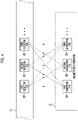
- the first generation coil 39 shown in Fig. 4 has different distance and direction from each of the first to third detection coils 25, as shown by a solid line. Therefore, the magnetic field measurement results of the first to third detection coils 25 for the magnetic field MF generated by one first generation coil 39 are different.
- a relationship between each of the second generation coil 39 and the third generation coil 39 and each of the first to third detection coils 25 is the same.
- the magnetic field measurement result of one first detection coil 25 for the magnetic field MF of each generation coil 39 is different.
- the first to third generation coils 39 is the X-axis coil, the Y-axis coil, and the Z-axis coil, respectively.
- a three-dimension coordinate position of the first detection coil 25 corresponding to the XYZ coordinate axes can be detected based on the magnetic field measurement result of one first detection coil 25 for the magnetic field MF of each of the X-axis coil, the Y-axis coil, and the Z-axis coil.
- the shape of the insertion part 17 can be detected.
- an angle of each detection coil 25 is detected in addition to the three-dimension coordinate position of each detection coil 25.
- the shape of the insertion part 17 is detected based on the information of the three-dimension coordinate position and the angle. In the following, in order to avoid complication, the description regarding the angle will be omitted and only the three-dimension coordinate position will be described.
- Fig. 5 is an explanatory diagram for describing an example of the magnetic field measurement data 55 acquired by the magnetic field measurement control unit 58.
- the magnetic field measurement control unit 58 detects the plurality of magnetic fields MF generated by the plurality of generation coils 39 by the plurality of detection coils 25 and acquires the magnetic field measurement data 55 including the plurality of magnetic field measurement results output from the detection coils 25.
- (1) to (4) are data strings showing the magnetic field measurement results of the plurality of detection coils 25 with respect to the magnetic fields MF generated by the generation coils 39, respectively.
- "D11” is a magnetic field measurement result in which the magnetic field MF generated by the first generation coil 39 is detected by the first detection coil 25.
- “D12” is a magnetic field measurement result in which the magnetic field MF generated by the first generation coil 39 is detected by the "second detection coil”.
- “D42” is a magnetic field measurement result in which the magnetic field MF generated by the fourth generation coil 39 is detected by the second detection coil 25.
- “D43” is a magnetic field measurement result in which the magnetic field MF generated by the fourth generation coil 39 is detected by the third detection coil 25.
- the magnetic field measurement control unit 58 sequentially acquires the magnetic field measurement results of the detection coils 25 while synchronizing with a magnetic field generation timing of each generation coil 39 in the magnetic field generator 13.
- the magnetic field measurement control unit 58 acquires, for example, the magnetic field measurement results of all of the detection coils 25 for the magnetic fields MF of all of the generation coils 39 in one magnetic field measurement period defined by a synchronization signal described below.
- the magnetic field measurement control unit 58 acquires the magnetic field measurement data 55 including the plurality of magnetic field measurement results relating to all of combinations of the generation coils 39 and the detection coils 25 in one magnetic field measurement period.
- the magnetic field measurement data 55 including the plurality of magnetic field measurement results relating to all of such combinations is referred to as total magnetic field measurement data.
- the magnetic field measurement data 55 shall include the total magnetic field measurement data.
- the image signal output unit 59 adds a frame start signal VD to each of the plurality of frame image signals 61 sequentially input from the signal processing unit 57, and outputs the frame image signal 61.
- "frame 1", “frame 2", “frame 3” ... are frame numbers indicating output order of the plurality of frame image signals 61, which are shown for convenience.
- the frame start signal VD is a vertical synchronization signal, for example.
- the image signal output unit 59 adds the magnetic field measurement data 55 to the frame image signal 61 and outputs the frame image signal 61. That is, the frame start signal VD and the magnetic field measurement data 55 are included in all of the frame image signals 61 output by the image signal output unit 59. As shown in Fig. 6 , the magnetic field measurement data 55 is added to a signal invalid region ND between the frame image signals 61, which corresponds to a blanking time of the imaging element 53. The blanking time is a vertical blanking period, for example. As described above, the frame start signal VD is also the signal included in the vertical blanking period of the plurality of frame image signals 61.
- the image signal output unit 59 outputs the frame image signal 61 to the LD 36 described above via the signal cable 32.
- the LD 36 transmits the optical signal obtained by converting the frame image signal 61 into the optical signal to the PD 37 of the light source device 11.
- the image signal output unit 59 outputs the frame image signal 61 acquired from the imaging element 53 via the signal processing unit 57 to the outside of the endoscope 10.
- the image signal output unit 59 functions as a synchronization signal generation unit.
- the light source device 11 includes an illumination light source 63, the PD 37, a light source control unit 64, a signal relay unit 62, and a communication interface 65.
- the illumination light source 63 is configured to include a semiconductor light source, such as the laser diode (LD) or a light emitting diode (LED), and is a white light source which emits white light having a wavelength range from a red region to a blue region as the illumination light.
- a special light source that emits special light, such as purple light and infrared light, may be used as the illumination light source 63.
- the illumination light emitted from the illumination light source 63 is incident on the incident end of the light guide 33 described above.
- the light source control unit 64 is configured to include various arithmetic circuits including the CPU and various memories, and controls the operation of each unit of the light source device 11, such as the illumination light source 63.
- the PD 37 receives the optical signal transmitted from the LD 36.
- the PD 37 converts the frame image signal 61 received in the form of the optical signal into the form of the original electric signal, and inputs the converted frame image signal 61 to the signal relay unit 62.
- the signal relay unit 62 is configured by, for example, a field programmable gate array (FPGA).
- the FPGA is a processor of which a circuit configuration can be changed after manufacturing, and the circuit configuration includes various arithmetic circuits and various memory circuits.
- the navigation device 12 includes an image signal acquisition unit 68, an insertion state detection unit 70, a magnetic field generation control unit 71, a display output unit 74, and an image generation unit 77.
- Each unit of the navigation device 12 is configured by various arithmetic circuits (not shown) including one or a plurality of CPUs, and is operated by executing a control program stored in a memory (not shown).
- the image signal acquisition unit 68 acquires the frame image signal 61 from the signal relay unit 62 via the communication interface 65. Further, the image signal acquisition unit 68 outputs the acquired frame image signal 61 to the display output unit 74.
- the image signal acquisition unit 68 extracts the frame start signal VD and the magnetic field measurement data 55 included in the frame image signal 61, and outputs the extracted frame start signal VD and the magnetic field measurement data 55 to the insertion state detection unit 70. In addition, the image signal acquisition unit 68 extracts the frame start signal VD from the frame image signal 61, and outputs the extracted frame start signal VD to the magnetic field generation control unit 71.
- the insertion state detection unit 70 detects the insertion state of the insertion part 17 of the endoscope 10 inserted into the body of the subject H based on the frame start signal VD and the magnetic field measurement data 55 acquired from the image signal acquisition unit 68.
- the insertion state detection unit 70 includes a position detection unit 72 and an insertion part shape detection unit 73.
- the position detection unit 72 detects a position of each detection coil 25 based on the frame start signal VD and the magnetic field measurement data 55.
- a determination unit 72A is provided in the position detection unit 72.
- the determination unit 72A determines the plurality of magnetic field measurement results included in the magnetic field measurement data 55 with reference to a correspondence relationship 75.
- the correspondence relationship 75 is information indicating storage order of the plurality of magnetic field measurement results corresponding to a plurality of combinations of the generation coils 39 and the detection coils 25 included in the magnetic field measurement data 55.
- the determination unit 72A determines which combination of each generation coil 39 and each detection coil 25 corresponds to each magnetic field measurement result included in the magnetic field measurement data 55 based on the correspondence relationship 75.
- generation order in which the generation coils 39 generate the magnetic field MF with the frame start signal VD as a reference and acquisition order of the magnetic field measurement results of the detection coils 25 for the magnetic field MF of one generation coil 39 are decided.
- the plurality of magnetic field measurement results corresponding to the combinations of the generation coils 39 and the detection coils 25 are stored in the magnetic field measurement data 55 depending on the generation order and the acquisition order.
- the determination unit 72A can determine which combination of the plurality of magnetic field measurement results included in the magnetic field measurement data 55 (for example, "D11", “D12", “D13”, ...) corresponds to each magnetic field measurement result by referring to the correspondence relationship 75 that defines the storage order with the frame start signal VD as a reference.
- the position detection unit 72 detects, as coil position data, the position of each detection coil 25, specifically, the three-dimension coordinate position based on the plurality of magnetic field measurement results determined by the determination unit 72A.
- the coil position data is a relative position with the magnetic field generator 13 as a reference.
- PI indicates the three-dimension coordinate position (here, x1, y1, z1) of the first detection coil 25. The same applies to P2, P3, P4, and the like.
- the position detection unit 72 outputs coil position data 76 to the insertion part shape detection unit 73.
- the insertion part shape detection unit 73 detects the shape of the insertion part 17 in the body of the subject H based on the coil position data 76 input from the position detection unit 72.
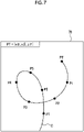
- Fig. 7 is an explanatory diagram for describing an example of a shape detection process of the insertion part 17 by the insertion part shape detection unit 73.
- the insertion part shape detection unit 73 performs an interpolation process of performing interpolation on each position with a curve based on the position (here, P1, P2, ...) of each detection coil 25 indicated by the coil position data 76, derives a central axis C of the insertion part 17, generates insertion part shape data 78 showing the shape of the insertion part 17.
- the interpolation process of performing interpolation with a curve is, for example, Bezier curve interpolation.
- the insertion part shape data 78 includes a distal end position PT of the distal end part 23 of the insertion part 17.
- the insertion part shape detection unit 73 outputs the insertion part shape data 78 to the image generation unit 77.
- the insertion state detection unit 70 repeatedly performs a determination process by the determination unit 72A, a position detection process of detecting the coil position data 76 of each detection coil 25, a shape detection process of the insertion part 17, and an output of the insertion part shape data 78 each time the image signal acquisition unit 68 acquires new frame image signal 61.
- the image generation unit 77 generates the shape display image 42 based on the insertion part shape data 78. As shown in Fig. 8 , a modeling unit 77A and a rendering unit 77B are provided in the image generation unit 77. As will be described in detail below, in the image generation unit 77, the modeling unit 77A generates a 3 dimension (D) model of the insertion part 17 based on the insertion part shape data 78, and the rendering unit 77B performs a rendering process on the 3D model of the insertion part 17, so that the 2 dimension (D) shape display image 42 showing the shape of the insertion part 17 is generated. The image generation unit 77 outputs data of the generated shape display image 42 to the processor device 14.
- the image generation unit 77 updates the shape display image 42 each time new insertion part shape data 78 is input. Further, the image generation unit 77 outputs the updated data of the shape display image 42 to the processor device 14 each time the shape display image 42 is updated.
- the navigation device 12 is an example of an endoscope shape display control device according to the technology of the present disclosure that performs a display control of the shape display image 42.
- the magnetic field measurement data 55 is data obtained by using the plurality of detection coils 25 which are an example of a plurality of magnetic field detection elements according to the technology of the present disclosure provided in the insertion part 17 of the endoscope 10.
- the insertion part shape data 78 is information based on the magnetic field measurement data 55, and is an example of information according to the technology of the present disclosure for imaging the shape of the insertion part 17 of the endoscope 10 inserted in the subject H, which is an example of the subject.
- the image generation unit 77 generates the shape display image 42 obtained by imaging the shape of the insertion part 17 based on the insertion part shape data 78. That is, the image generation unit 77 is an example of an image generation unit according to the technology of the present disclosure, and is also an example of an information acquisition unit that acquires the information for imaging the shape of the insertion part.
- the display output unit 74 outputs the frame image signal 61 previously input from the image signal acquisition unit 68 described above and the data of the shape display image 42 input from the image generation unit 77 to the processor device 14 via communication interfaces 80A and 80B. In this case, the display output unit 74 associates the frame image signal 61 with the data of the shape display image 42 that corresponds in time with the frame image signal 61, and outputs the data to the processor device 14.
- the processor device 14 has a display input unit 82 and a display control unit 83.
- the display input unit 82 sequentially outputs, to the display control unit 83, the data of the frame image signal 61 and the shape display image 42 sequentially input from the display output unit 74 via the communication interfaces 80A and 80B.
- the display control unit 83 receives the input of the frame image signal 61 from the display input unit 82, and displays the observation image 41 (for example, the motion picture) based on the frame image signal 61 on the monitor 15 (see Figs. 1 and 2 ). In addition, the display control unit 83 receives input of the data of the shape display image 42 from the display input unit 82 and displays the shape display image 42 (for example, the motion picture) on the monitor 15 (see Figs. 1 and 2 ).
- Fig. 9 is a flowchart for describing a flow of a generation process of the shape display image 42 by the image generation unit 77.
- the image generation unit 77 acquires the insertion part shape data (step S1).
- the modeling unit 77A performs a modeling process of generating the 3D model of the insertion part 17 based on the insertion part shape data 78 (step S2).
- a cylindrical 3D model M having a diameter corresponding to a display scale of the insertion part 17 with the central axis C of the insertion part 17 in the insertion part shape data 78 as a central axis is generated.
- the rendering unit 77B executes a light source position setting process of setting the light source position in a case of rendering the 3D model M of the insertion part 17 (step S3).
- the light source position is set to a position with respect to the upper surface 16A of the bed 16 at which the light is emitted from an upper side in a virtual space in which the 3D model M is generated. Specifically, in a real space, in a case in which the magnetic field generator 13 and the bed 16 are installed on the same floor surface, a horizontal direction of the magnetic field generator 13 and the upper surface 16A of the bed 16 are in a parallel relationship.
- a plane parallel to the upper surface 16A of the bed 16 is set as an X-Y plane, and a Z-axis orthogonal to the X-Y plane is set. Further, in the virtual space, the light source position is set such that the light is emitted from an upper side of the set Z-axis to a lower side thereof.
- the rendering unit 77B executes a camera position setting process of setting a camera position (also referred to as a viewpoint position) in a case of rendering the 3D model M of the insertion part 17 (step S4).
- the camera position is set to a position with respect to the upper surface 16A of the bed 16 in the virtual space in which the 3D model M of the insertion part 17 is observed from the upper side of the Z-axis in the same manner as the light source position.
- the rendering unit 77B executes a texture setting process of finishing a surface of the 3D model M in a case of rendering the 3D model M of the insertion part 17 (step S5).
- a texture setting process a process of adding a pattern, which is a content of the texture, is performed on the surface of the insertion part 17.
- the pattern refers to a display aspect other than a plain single color.
- the pattern of the present embodiment is a gradation that is changed continuously from green to blue from the distal end side to the proximal end side of the insertion part 17.
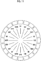
- the definition of color will be described using a hue circle of a Munsell display system shown in Fig. 11 .
- the hue circle represents the classification of tint of chromatic color. For example, it is a Munsell hue circle divided into 20 colors.
- symbols means red (R), yellow-red (YR), yellow (Y), green-yellow (GY), green (G), blue-green (BG), blue (B), purple-blue (PB), purple (P), and red purple (RP), respectively.
- hues obtained by further dividing each of these 10 types of hues into two for example, 5R and 10R for R are displayed.
- the green includes green-yellow (GY) and blue-green (BG) that are adjacent to each other on the right and left of green (G) in the hue circle.
- colors from 5 GY to 10 BG correspond to green.
- Blue includes blue-green (BG) and purple-blue (PB) that are adjacent to each other on the right and left of blue (B) in the hue circle.
- the colors from 5BG to 10PB correspond to blue.
- green refers to a color containing a G element
- blue refers to a color containing a B element. The same applies to the definitions of other colors, such as red and yellow.
- the rendering unit 77B adds a gradation pattern to the surface of the 3D model M based on the set light source position and the set camera position.
- the surface of the 3D model M added with the pattern is subjected to a shading process of performing shading corresponding to the light source.
- the rendering unit 77B performs the rendering process of generating the 2D shape display image 42 showing the shape of the insertion part 17 (step S6).
- the shape display image 42 is generated, as shown in Fig. 12 .
- the shape display image 42 is configured to include an image showing the insertion part 17 and an image, which is a background thereof.
- the insertion part 17 in the shape display image 42 or more accurately, the image of the insertion part 17 in the shape display image 42, is simply referred to as the insertion part for simplification, and for distinguish from the actual insertion part 17, a reference numeral 17G is added and is referred to as an insertion part 17G.
- the surface of the insertion part 17G is displayed in the display aspect in which the gradation that is changed continuously from green to blue is added from the distal end side to the proximal end side of the insertion part 17G.
- the generation process of the shape display image 42 is repeated each time the insertion part shape data 78 is updated.
- the insertion part 17 of the endoscope 10 may be bent in a loop shape in the body of the subject H.
- different portions of the insertion part 17G intersect with each other in the shape display image 42 depending on the camera position set in the rendering process.
- the insertion part 17G may be displayed in a thin line shape in the shape display image 42. Therefore, in a case in which the entire insertion part 17G is displayed in a plain single color (for example, black), there is a problem that it is difficult for a user to instantaneously determine the front and rear of an intersection portion 17GX even in a case in which the intersection portion 17GX shown in Fig. 12 is subjected to a shade line process or a hidden surface process.
- the insertion part 17G is displayed by being added with the gradation pattern which is changed continuously from green to blue from the distal end side to the proximal end side of the insertion part 17G.
- the color of the insertion part 17G is different between the front and rear of the intersection portion 17GX, so that it is possible to easily determine the front and rear of the intersection portion 17GX.
- it is easy to visually recognize an overlapping condition of the insertion parts 17G in the shape display image 42.
- the gradation pattern is added to the entire region of the insertion part 17G displayed on the shape display image 42. Therefore, no matter where in the entire region of the displayed insertion part 17G is the intersection portion 17GX, it is possible to easily determine the front and rear of the intersection portion 17GX.
- the entire region of the displayed insertion part 17G is added with the gradation pattern, but the entire region does not necessarily have to be added with the gradation pattern.
- the intersection portion 17GX is hardly generated on the distal end side and the proximal end side, it is not necessary to add the gradation pattern to a partial region of the distal end side and the proximal end side.
- a region having a length of 20% from the distal end and a region having a length of 20% from the proximal end may be used as regions without the gradation pattern.
- the image can be more natural than a case in which the color is changed stepwise.
- the effect of suppressing irritation to the eyes can be expected as compared with a case in which the insertion part 17G is displayed by colors of a warm color system, such as red, orange, and yellow.
- the gradation that is changed from green to blue has been described as an example of the gradation, but a combination of a plurality of changing colors may be other than the colors of the example described above. For example, it may be a gradation that is changed from red to orange. In addition, the color of the gradation may be changed in accordance with the user's setting.
- the gradation pattern in which the color is changed continuously has been described as the pattern to be added to the surface of the insertion part 17G in the shape display image 42, but the pattern may be other than the gradation.
- the gradation pattern does not have to be an aspect in which the color is changed continuously, but an aspect in which the color is changed stepwise may be adopted.
- the surface of the insertion part 17G is added with the gradation pattern that is changed stepwise to a different color from the distal end side to the proximal end side.
- the colors of the insertion part 17G have different color scheme in the front and rear the intersection portion 17GX, so that it is possible to easily determine the front and rear of the intersection portion 17GX.
- the gradation in which the color is changed continuously is preferable in that the color change is natural and the appearance is good.
- the pattern may be a pattern other than the gradation, and may be a pattern in which a plurality of colors are combined.
- a plurality of colors means, for example, a combination of colors in which at least one of lightness, chroma saturation, or hue is different from each other.
- the pattern may be a vertical stripe pattern of a plurality of colors which extends in the longitudinal direction of the insertion part 17G. Even in this case, since the vertical stripes intersect with each other in the front and rear of the intersection portion 17GX, it is possible to easily determine the front and rear of the intersection portion 17GX.
- the pattern may be a horizontal stripe pattern added in a ring shape around an axis of the insertion part 17G. Even in this case, since the horizontal stripes intersect with each other in the front and rear of the intersection portion 17GX, it is possible to easily determine the front and rear of the intersection portion 17GX.
- Such a vertical stripe pattern and such a horizontal stripe pattern may be constituted by pinstripes, or an aspect may be adopted in which the vertical stripe pattern and the horizontal stripe pattern are constituted by a plurality of strip-shaped stripes having a width and the plurality of stripes are color-coded with different colors.
- a wire frame pattern may be used as in a shape display image 42D shown in Fig. 16 .
- the wire frame expresses a three-dimension object by connecting a plurality of points having three-dimension coordinates in accordance with a certain rule.
- the wire frame pattern is a display aspect in which the wire frame is displayed as the pattern on the surface of the insertion part 17G Even with such a pattern, the same effect as in the example described above can be obtained.
- the light source position and the camera position in a case of performing the rendering process, a case will be described in which, in a case in which the plane parallel to the upper surface 16A of the bed 16 is defined as the X-Y plane, a light irradiation direction and a viewpoint direction are set to a state of being from the upper side of the Z-axis to the lower side thereof.
- the light source position and the camera position are not limited to the above, and may be set in any direction based on an instruction input of the user. Examples of the direction in which the viewpoint direction is from the upper side of the Z-axis of the bed 16 to the lower side thereof include the following two directions.
- One direction is the viewpoint of observing the upper surface 16A of the bed 16 from directly above the bed 16, that is, from a normal direction to the X-Y plane.
- the other direction is a viewpoint of a bird's-eye view of the upper surface 16A of the bed 16 from an oblique direction of the bed 16.
- a plurality of viewpoints may be switched and parallel viewpoints may be set.
- each generation coil 39 generates the magnetic field MF having the same frequency, but the frequencies of the magnetic fields MF generated by the generation coils 39 may be different.
- the magnetic field measurement unit including the magnetic field measurement control unit 58 is disposed in the endoscope 10 and the magnetic field generation control unit 71 is disposed in the navigation device 12, on the contrary, the magnetic field generation control unit 71 may be disposed in the endoscope 10, and the magnetic field measurement unit may be disposed in the navigation device 12.
- various processors in the following can be used.
- the various processors include the central processing unit (CPU) that is a general-purpose processor executing the software and functioning as the various processing units, as well as a programmable logic device (PLD) that is a processor of which a circuit configuration can be changed after manufacture, such as a field programmable gate array (FPGA) and/or a dedicated electric circuit that is a processor having a circuit configuration that is designed for exclusive use in order to execute a specific process, such as an application specific integrated circuit (ASIC).
- CPU central processing unit
- PLD programmable logic device
- FPGA field programmable gate array
- ASIC application specific integrated circuit
- One processing unit may be configured by one of the various processors, or may be a combination of two or more processors of the same type or different types (for example, a combination of a plurality of FPGAs and/or a combination of a CPU and an FPGA). In this way, as the hardware structure, various processing units are configured by one or more of various processors described above.
- circuitry circuitry in which circuit elements such as semiconductor elements are combined.
- An endoscope display control device having the information acquisition unit and the image generation unit may be realized by the computer of which the processor is the CPU.
- a program for causing the CPU to function as the information acquisition unit and the image generation unit is an operation program of the endoscope display control device.
- the technology of the present disclosure extends to a computer-readable storage medium that stores the operation program non-transitorily, in addition to the operation program of the endoscope display control device.
- An endoscope shape display control device comprising an information acquisition processor that acquires information for imaging a shape of an insertion part of an endoscope inserted into a subject, and an image generation processor that generates a shape display image displaying the shape of the insertion part based on the acquired information, and displays the insertion part with a pattern added on a surface thereof in the shape display image.
- a and/or B is synonymous with "at least one of A or B”. That is, “A and/or B” means that it may be only A, only B, or a combination of A and B.
- a and/or B means that it may be only A, only B, or a combination of A and B.
- JP2019-134865A filed on July 22, 2019 is incorporated in the present specification by reference in its entirety. All documents, patent applications, and technical standards described in the present specification are incorporated in the present specification by reference to the same extent as a case in which each document, patent application, and technical standard are specifically and individually noted to be incorporated by reference.
Landscapes
- Health & Medical Sciences (AREA)
- Life Sciences & Earth Sciences (AREA)
- Surgery (AREA)
- Engineering & Computer Science (AREA)
- Physics & Mathematics (AREA)
- Optics & Photonics (AREA)
- Biomedical Technology (AREA)
- Molecular Biology (AREA)
- Pathology (AREA)
- Nuclear Medicine, Radiotherapy & Molecular Imaging (AREA)
- Biophysics (AREA)
- Heart & Thoracic Surgery (AREA)
- Medical Informatics (AREA)
- Radiology & Medical Imaging (AREA)
- Animal Behavior & Ethology (AREA)
- General Health & Medical Sciences (AREA)
- Public Health (AREA)
- Veterinary Medicine (AREA)
- Signal Processing (AREA)
- Microelectronics & Electronic Packaging (AREA)
- Endoscopes (AREA)
- Instruments For Viewing The Inside Of Hollow Bodies (AREA)
Abstract
Description
- The present disclosure relates to an endoscope shape display control device, an operation method of an endoscope shape display control device, and an operation program of an endoscope shape display control device.
- An endoscope that observes a lower digestive tract, such as the large intestine, is known. The lower digestive tract is intricately bent, unlike an upper digestive tract, such as an esophagus, which extends relatively linearly. Therefore, the endoscope, which is inserted into the lower digestive tract of a subject, such as a patient, an insertion part of the endoscope is also intricately bent. In order to grasp a shape of the insertion part of the endoscope inserted into the subject, an endoscope shape detection device that detects the shape of the insertion part of the endoscope in the subject (for example, see
JP2004-551A - The endoscope shape detection device disclosed in
JP2004-551A JP2004-551A - An imaging procedure in the endoscope shape detection device of
JP2004-55 1A JP2004-551A - In a case in which the insertion part of the endoscope is bent in a loop shape in the subject, different portions of the insertion part intersect with each other in the shape display image depending on the set viewpoint.
JP2004-551A - However, depending on a display magnification of the shape display image, the insertion part of the endoscope may be displayed in a thin line shape in the shape display image. Therefore, there is a problem that it is difficult for the user to instantaneously determine the front and rear of the intersection portion even in a case in which the shade line process or the hidden surface process is performed on the intersection portion.
- The technology of the present disclosure is to provide an endoscope shape display control device, an operation method of an endoscope shape display control device, and an operation program of the endoscope shape display control device capable of displaying a shape display image in which an overlapping condition of an insertion part is easily visually recognized in the shape display image in which a shape of the insertion part of an endoscope in a state of being inserted into a subject is displayed.
- An aspect of the present disclosure relates to an endoscope shape display control device comprising at least one processor, in which the processor acquires information for imaging a shape of an insertion part of an endoscope inserted in a subject, and displays, in a case of generating a shape display image in which the shape of the insertion part is displayed based on the acquired information, the insertion part with a pattern added on a surface thereof in the shape display image.
- In the endoscope shape display control device according to the aspect described above, the pattern may be added to an entire region of the insertion part displayed in the shape display image.
- In addition, in the endoscope shape display control device according to the aspect described above, the pattern may be a gradation in which a color is changed continuously or stepwise from one of a distal end side or a proximal end side of the insertion part to the other thereof. In this case, the gradation may be changed from green to blue.
- In addition, in the endoscope shape display control device according to the aspect described above, the pattern may be a stripe pattern.
- In addition, in the endoscope shape display control device according to the aspect described above, the pattern may be a wire frame pattern.
- In addition, in the endoscope shape display control device according to the aspect described above, the processor may perform a shading process on the insertion part in addition to the pattern.
- In addition, in the endoscope shape display control device according to the aspect described above, the information for imaging the shape of the insertion part may be information based on magnetic field measurement data obtained by using a plurality of magnetic field generation elements or a plurality of magnetic field detection elements provided in the insertion part.
- Another aspect of the present disclosure relates to an operation method of an endoscope shape display control device, the method comprising an information acquisition step of acquiring information for imaging a shape of an insertion part of an endoscope inserted in a subject, and an image generation step of generating a shape display image in which the shape of the insertion part is displayed based on the acquired information and displaying the insertion part with a pattern added on a surface thereof in the shape display image.
- Still another aspect of the present disclosure relates to an operation program of an endoscope shape display control device, the program causing a computer to function as an information acquisition unit that acquires information for imaging a shape of an insertion part of an endoscope inserted in a subject, and an image generation unit that generates a shape display image in which the shape of the insertion part is displayed based on the acquired information, the image generation unit displaying the insertion part with a pattern added on a surface thereof in the shape display image.
- According to the technology of the present disclosure, it is possible to provide an endoscope shape display control device, an operation method of an endoscope shape display control device, and an operation program of the endoscope shape display control device capable of displaying a shape display image in which an overlapping condition of an insertion part is easily visually recognized in the shape display image in which a shape of the insertion part of an endoscope in a state of being inserted into a subject is displayed.
-
-
Fig. 1 is an explanatory diagram showing a state of an endoscopic examination using an endoscope system. -
Fig. 2 is a schematic view showing an overall configuration of the endoscope system. -
Fig. 3 is a block diagram showing an electric configuration of the endoscope system. -
Fig. 4 is an explanatory diagram showing a state in which a plurality of detection coils detect a magnetic field generated by a plurality of generation coils. -
Fig. 5 is an explanatory diagram showing an example of magnetic field measurement data. -
Fig. 6 is an explanatory diagram for describing a determination process by a determination unit and a position detection process of each detection coil by a position detection unit. -
Fig. 7 is an explanatory diagram showing an example of a shape detection process of an insertion part. -
Fig. 8 is a functional block diagram of an image generation unit. -
Fig. 9 is a flowchart for describing a flow of a generation process of a shape display image by a display control unit. -
Fig. 10 is an explanatory diagram showing an example of a 3D model generation process of the insertion part. -
Fig. 11 is a diagram showing an example of a hue circle. -
Fig. 12 is a diagram showing an example of a shape display image. -
Fig. 13 is a diagram showing an example of the shape display image. -
Fig. 14 is a diagram showing an example of the shape display image. -
Fig. 15 is a diagram showing an example of the shape display image. -
Fig. 16 is a diagram showing an example of the shape display image. -
Fig. 1 is a schematic view showing an overall configuration of anendoscope system 9 comprising an endoscope shape display control device according to the technology of the present disclosure. As shown inFig. 1 , theendoscope system 9 comprises anendoscope 10, alight source device 11, anavigation device 12, amagnetic field generator 13, aprocessor device 14, and amonitor 15. Theendoscope system 9 is used for an endoscopic examination in a body of a subject H, such as a patient. The subject H is an example of a subject. Theendoscope 10 is, for example, an endoscope inserted into the digestive tract, such as the large intestine, and is a soft endoscope having flexibility. Theendoscope 10 has aninsertion part 17 to be inserted into the digestive tract, anoperating part 18 connected sequentially to a proximal end side of theinsertion part 17 and gripped by an operator to perform various operations, and auniversal cord 19 connected sequentially to theoperating part 18. - The endoscopic examination is performed, for example, in a state in which the subject H lies on an
upper surface 16A of abed 16. In a case of a large intestine examination, theinsertion part 17 of theendoscope 10 is inserted into the digestive tract from an anus by an operator OP who is the doctor. Thelight source device 11 supplies illumination light that illuminates an inside of the large intestine, which is an observation site, to theendoscope 10. Theprocessor device 14 generates anobservation image 41 by processing an image captured by theendoscope 10. Theobservation image 41 is displayed on themonitor 15. The operator OP proceeds with the endoscopic examination while confirming theobservation image 41. Theobservation image 41 displayed on themonitor 15 is basically a motion picture, but it is also possible to display a still picture as theobservation image 41 as needed. - In addition, the
endoscope system 9 has a navigation function of navigating technique, such as an insertion operation of theendoscope 10 performed by the operator OP. Here, the navigation means supporting the technique of theendoscope 10 of the operator OP by presenting an insertion state including the position and the shape of theinsertion part 17 of theendoscope 10 in the body of the subject H to the operator OP. By the navigation function, the insertion state of theinsertion part 17 is detected using a magnetic field MF and the detected insertion state is presented. - The navigation function is realized by the
navigation device 12, themagnetic field generator 13, and a magnetic field measurement device in theendoscope 10 described below. Themagnetic field generator 13 generates the magnetic field MF Themagnetic field generator 13 is attached to, for example, a stand and is disposed beside thebed 16 on which the subject H lies. In addition, themagnetic field generator 13 is disposed within a range in which the generated magnetic field MF reaches the body of the subject H. - The magnetic field measurement device in the
endoscope 10 detects the magnetic field MF generated by themagnetic field generator 13 and measures the intensity of the detected magnetic field MF. Thenavigation device 12 detects the insertion state of theinsertion part 17 by deriving a relative position between themagnetic field generator 13 and theinsertion part 17 based on a magnetic field measurement result by the magnetic field measurement device. Theprocessor device 14 generates ashape display image 42, which shows the insertion state detected by thenavigation device 12. - The
monitor 15 displays theobservation image 41 and theshape display image 42. Note that themonitor 15 that displays theobservation image 41 and theshape display image 42 may be provided separately. - As shown in
Fig. 2 , theinsertion part 17 is a tubular portion having a small diameter and a long length, and is configured by asoft part 21, abendable part 22, and adistal end part 23, which are connected sequentially from the proximal end side to the distal end side. Thesoft part 21 has flexibility. Thebendable part 22 is a part that can be bent by the operation of the operatingpart 18. An imaging apparatus 48 (seeFig. 3 ) and the like are disposed at thedistal end part 23. In addition, although not shown inFig. 2 , an illumination window 46 (seeFig. 3 ) that illuminates the observation site with the illumination light, an observation window 47 (seeFig. 3 ) on which subject light of the illumination light reflected by the subject is incident, a treatment tool outlet (not shown) for a treatment tool to protrude, and a cleaning nozzle (not shown) for cleaning theobservation window 47 by injecting gas and water into theobservation window 47 are provided on a distal end surface of thedistal end part 23. -
Alight guide 33, asignal cable 32, an operation wire (not shown), and a pipe line for inserting the treatment tool (not shown) are provided in theinsertion part 17. Thelight guide 33 extends from theuniversal cord 19 and guides the illumination light supplied from thelight source device 11 to theillumination window 46 at thedistal end part 23. Thesignal cable 32 is used for power supply to theimaging apparatus 48 in addition to communication of an image signal from theimaging apparatus 48 and a control signal for controlling theimaging apparatus 48. Like thelight guide 33, thesignal cable 32 also extends from theuniversal cord 19 and is arranged to thedistal end part 23. - The operation wire is a wire for operating the
bendable part 22, and is arranged from the operatingpart 18 to thebendable part 22. The pipe line for inserting the treatment tool is a pipe line for inserting the treatment tool (not shown), such as forcep, and is arranged from the operatingpart 18 to thedistal end part 23. In addition, a fluid tube for air/water supply is provided in theinsertion part 17. The fluid tube supplies thedistal end part 23 with gas and water for cleaning theobservation window 47. - In addition, in the
insertion part 17, a plurality of detection coils 25 are provided from thesoft part 21 to thedistal end part 23 at preset intervals. Eachdetection coil 25 corresponds to a magnetic field detection element which detects the magnetic field MF Eachdetection coil 25 is affected by the magnetic field MF generated from themagnetic field generator 13, so that an induced electromotive force is generated by an operation of electromagnetic induction, and an induced current is generated by the induced electromotive force. A value of the induced current generated from eachdetection coil 25 represents the intensity of the magnetic field MF detected by eachdetection coil 25, which is the magnetic field measurement result. That is, the magnetic field measurement result refers to a value depending on the magnitude of the induced current, which represents the intensity of the magnetic field MF. - The operating
part 18 is provided with various operation members operated by the operator. Specifically, the operatingpart 18 is provided with two types of bending operation knobs 27, an air/water supply button 28, and asuction button 29. Each of the two types of bending operation knobs 27 is connected to the operation wire, and is used for a right-left bending operation and an up-down bending operation of thebendable part 22. In addition, the operatingpart 18 is provided with a treatmenttool inlet port 31 which is an inlet of the pipe line for inserting the treatment tool. - The
universal cord 19 is a connection cord that connects theendoscope 10 to thelight source device 11. Theuniversal cord 19 encompasses thesignal cable 32, thelight guide 33, and the fluid tube (not shown). In addition, aconnector 34 connected to thelight source device 11 is provided at an end part of theuniversal cord 19. - By connecting the
connector 34 to thelight source device 11, thelight source device 11 supplies the power, the control signal, the illumination light, the gas, and the water necessary for operating theendoscope 10 to theendoscope 10. In addition, the image signal of the observation site acquired by the imaging apparatus 48 (seeFig. 2 ) of thedistal end part 23 and the magnetic field measurement result based on a detection signal of eachdetection coil 25 are transmitted from theendoscope 10 to thelight source device 11. - The
connector 34 is not electrically connected to thelight source device 11 by wire using a metal signal line or the like, and instead, theconnector 34 and thelight source device 11 are connected to each other so as to be capable of optical communication (for example, non-contact type communication). Theconnector 34 transmits and receives the control signal exchanged between theendoscope 10 and thelight source device 11 and transmits the image signal and the magnetic field measurement result from theendoscope 10 to thelight source device 11 by optical communication. Theconnector 34 is provided with a laser diode (hereinafter, referred to as LD) 36 connected to thesignal cable 32. - The
LD 36 is used for transmitting a large amount of data from theendoscope 10 to thelight source device 11, specifically, transmitting the image signal and the magnetic field measurement result. TheLD 36 transmits the image signal and the magnetic field measurement result, which has been originally in a form of the electric signal, in a form of an optical signal to a photodiode (hereinafter, referred to as PD) 37 provided in thelight source device 11. - Note that, although not shown, apart from the
LD 36 and thePD 37, both theconnector 34 and thelight source device 11 are provided with a light transmission and reception unit that converts a small amount of the control signal exchanged between theendoscope 10 and thelight source device 11 into the optical signal and transmits and receives the converted optical signal. Moreover, theconnector 34 is provided with a power reception unit (not shown) that receives the power by wireless power supply from a power feed unit (not shown) of thelight source device 11. - The
light guide 33 in theconnector 34 is inserted into thelight source device 11. In addition, the fluid tube (not shown) in theconnector 34 is connected to an air/water supply device (not shown) via thelight source device 11. As a result, thelight source device 11 and the air/water supply device supply the illumination light, the gas, and the water to theendoscope 10, respectively. - The
light source device 11 supplies the illumination light to thelight guide 33 of theendoscope 10 via theconnector 34, and supplies the gas and the water supplied from the air/water supply device (not shown) to the fluid tube (not shown) of theendoscope 10. In addition, thelight source device 11 receives the optical signal transmitted from theLD 36 by thePD 37, converts the received optical signal into the original image signal, which is the electric signal, and the magnetic field measurement result, and then outputs the converted image signal and the magnetic field measurement result to thenavigation device 12. - The
navigation device 12 outputs the image signal for generating theobservation image 41 input from thelight source device 11 to theprocessor device 14. In addition, thenavigation device 12 controls the drive of themagnetic field generator 13 described below, detects the shape and the like of theinsertion part 17 in the body of the subject H, and outputs a detection result to theprocessor device 14 as the information for generating theshape display image 42. - As described above, the
endoscope 10 in the present embodiment is one-connector type having oneconnector 34 connected to thelight source device 11. Theendoscope 10 is connected to each of theprocessor device 14 and thenavigation device 12 so as to be capable of communication via thelight source device 11 to which theconnector 34 is connected. - The
magnetic field generator 13 has a plurality of generation coils 39 corresponding to a plurality of magnetic field generation elements. Eachgeneration coil 39 includes an X-axis coil, a Y-axis coil, and a Z-axis coil that generate, by applying a drive current, an alternating current magnetic field (in other words, an alternating current magnetic field) in directions corresponding to XYZ coordinate axes of an orthogonal coordinate system XYZ, respectively. Eachgeneration coil 39 generates the magnetic field MF having the same frequency. The generation coils 39 generate the magnetic fields MF at different timings from each other under a control of thenavigation device 12, which will be described in detail below. -
Fig. 3 is a block diagram showing an electric configuration of theendoscope system 9. As shown inFig. 3 , theendoscope 10 includes thelight guide 33, anirradiation lens 45, theillumination window 46, theobservation window 47, theimaging apparatus 48, a magneticfield detection circuit 49, an integrated control circuit 50, thesignal cable 32, theLD 36, and the fluid tube and the cleaning nozzle (which are not shown). - The
light guide 33 is, for example, a large-diameter optical fiber or a bundle fiber. An incident end of thelight guide 33 is inserted into thelight source device 11 via theconnector 34. Thelight guide 33 is inserted into theconnector 34, theuniversal cord 19, and the operatingpart 18, and an emission end faces theirradiation lens 45 provided in thedistal end part 23 of theinsertion part 17. As a result, the illumination light supplied from thelight source device 11 to the incident end of thelight guide 33 is emitted to the observation site from theirradiation lens 45 through theillumination window 46 provided on the distal end surface of thedistal end part 23. Further, the illumination light reflected by the observation site is incident on an imaging surface of theimaging apparatus 48 as image light of the observation site through theobservation window 47 provided on the distal end surface of thedistal end part 23. - Note that one end side of the fluid tube (not shown) described above is connected to the air/water supply device (not shown) through the
connector 34 and thelight source device 11, and the other end side of the fluid tube (not shown) is connected to an air/water supply nozzle (not shown) provided on the distal end surface of thedistal end part 23 through theinsertion part 17 and the like. As a result, the gas or the water supplied from the air/water supply device (not shown) is injected into theobservation window 47 from the air/water supply nozzle (not shown) to clean theobservation window 47. - The
imaging apparatus 48 includes acondenser lens 52 and animaging element 53. Thecondenser lens 52 collects the image light of the observation site incident from theobservation window 47, and forms the collected image light of the observation site on the imaging surface of theimaging element 53. Theimaging element 53 is a complementary metal oxide semiconductor (CMOS) type or charge coupled device (CCD) type imaging element. Theimaging element 53 is, for example, a color imaging element in which any of red (R), green (G), or blue (B) microfilter is assigned to each pixel. Theimaging element 53 images the observation site, which is an observation target. More specifically, theimaging element 53 images the image light of the observation site imaged on the imaging surface (that is, converts the image light into the electric signal), and outputs the image signal of the observation site to the integrated control circuit 50. - In addition, the
imaging element 53 is provided with anoscillation unit 53a that outputs a reference signal (for example, a clock signal), such as a crystal oscillator, and theimaging element 53 outputs the image signal constituting the motion picture with the reference signal oscillated from theoscillation unit 53a as a reference. An interval of the reference signal defines a frame rate. The frame rate is, for example, 30 frames per second (fps). - The magnetic
field detection circuit 49 is electrically connected to eachdetection coil 25 in theinsertion part 17. The magneticfield detection circuit 49 outputs magneticfield measurement data 55 including the magnetic field measurement result of eachdetection coil 25 depending on the magnetic field MF generated from thegeneration coil 39 of themagnetic field generator 13 to the integrated control circuit 50. - The integrated control circuit 50 configured to include arithmetic circuits including various central processing units (CPU) and various memories, and controls the operations of the units of the
endoscope 10 in an integrated manner. The integrated control circuit 50 functions as asignal processing unit 57, a magnetic fieldmeasurement control unit 58, and an imagesignal output unit 59 by executing a control program stored in a memory (not shown). The magneticfield detection circuit 49 and the magnetic fieldmeasurement control unit 58 are combined to configure a magnetic field measurement unit. The magnetic field measurement unit measures a plurality of the magnetic fields MF originating from the generation coils 39 corresponding to the plurality of magnetic field generation elements based on the detection signals output by the detection coils 25, and outputs the magnetic field measurement result for each magnetic field MF. The magnetic field measurement unit and thedetection coil 25 are combined to configure the magnetic field measurement device. - The
signal processing unit 57 performs various signal processes on the image signals sequentially output from theimaging element 53. The signal process includes, for example, an analog signal process, such as a sampling two correlation pile process and a signal amplification process, and an analog/digital (A/D) conversion process of converting an analog signal into a digital signal after the analog signal process. The image signal after the signal process is performed is called aframe image signal 61. Thesignal processing unit 57 outputs theframe image signal 61 to the imagesignal output unit 59 depending on the frame rate. Theframe image signal 61 is used as motion picture data of the observation site. As described above, a plurality of the frame image signals 61 are the image signals that are acquired by theimaging element 53 executing motion picture imaging and are output at preset time intervals. - The magnetic field
measurement control unit 58 acquires the magneticfield measurement data 55 including a plurality of the magnetic field measurement results of the detection coils 25 via the magneticfield detection circuit 49, and outputs the acquired magneticfield measurement data 55 to the imagesignal output unit 59. - As shown in
Fig. 4 , even in a case in which the intensity of the magnetic field generated by eachgeneration coil 39 is the same, for example, the magnetic field measurement result of eachdetection coil 25 is changed depending on a distance and a direction between eachgeneration coil 39 that generates the magnetic field MF and eachdetection coil 25. For example, thefirst generation coil 39 shown inFig. 4 has different distance and direction from each of the first to third detection coils 25, as shown by a solid line. Therefore, the magnetic field measurement results of the first to third detection coils 25 for the magnetic field MF generated by onefirst generation coil 39 are different. A relationship between each of thesecond generation coil 39 and thethird generation coil 39 and each of the first to third detection coils 25 is the same. - In addition, on the contrary, even in a case in which the intensity of the magnetic field MF generated by each of the first to third generation coils 39 is the same, the magnetic field measurement result of one
first detection coil 25 for the magnetic field MF of eachgeneration coil 39 is different. Here, for example, a case is considered in which the first to third generation coils 39 is the X-axis coil, the Y-axis coil, and the Z-axis coil, respectively. In this case, a three-dimension coordinate position of thefirst detection coil 25 corresponding to the XYZ coordinate axes can be detected based on the magnetic field measurement result of onefirst detection coil 25 for the magnetic field MF of each of the X-axis coil, the Y-axis coil, and the Z-axis coil. The same applies to thesecond detection coil 25 and thethird detection coil 25. In a case in which the three-dimension coordinate positions of the detection coils 25 provided in theinsertion part 17 at preset intervals can be detected, the shape of theinsertion part 17 can be detected. - Note that, actually, based on the magnetic field measurement result, an angle of each
detection coil 25 is detected in addition to the three-dimension coordinate position of eachdetection coil 25. The shape of theinsertion part 17 is detected based on the information of the three-dimension coordinate position and the angle. In the following, in order to avoid complication, the description regarding the angle will be omitted and only the three-dimension coordinate position will be described. -
Fig. 5 is an explanatory diagram for describing an example of the magneticfield measurement data 55 acquired by the magnetic fieldmeasurement control unit 58. The magnetic fieldmeasurement control unit 58 detects the plurality of magnetic fields MF generated by the plurality of generation coils 39 by the plurality of detection coils 25 and acquires the magneticfield measurement data 55 including the plurality of magnetic field measurement results output from the detection coils 25. - In
Fig. 5 , (1) to (4) are data strings showing the magnetic field measurement results of the plurality of detection coils 25 with respect to the magnetic fields MF generated by the generation coils 39, respectively. For example, "D11" is a magnetic field measurement result in which the magnetic field MF generated by thefirst generation coil 39 is detected by thefirst detection coil 25. "D12" is a magnetic field measurement result in which the magnetic field MF generated by thefirst generation coil 39 is detected by the "second detection coil". Similarly, "D42" is a magnetic field measurement result in which the magnetic field MF generated by thefourth generation coil 39 is detected by thesecond detection coil 25. "D43" is a magnetic field measurement result in which the magnetic field MF generated by thefourth generation coil 39 is detected by thethird detection coil 25. - The magnetic field
measurement control unit 58 sequentially acquires the magnetic field measurement results of the detection coils 25 while synchronizing with a magnetic field generation timing of eachgeneration coil 39 in themagnetic field generator 13. The magnetic fieldmeasurement control unit 58 acquires, for example, the magnetic field measurement results of all of the detection coils 25 for the magnetic fields MF of all of the generation coils 39 in one magnetic field measurement period defined by a synchronization signal described below. As a result, the magnetic fieldmeasurement control unit 58 acquires the magneticfield measurement data 55 including the plurality of magnetic field measurement results relating to all of combinations of the generation coils 39 and the detection coils 25 in one magnetic field measurement period. - For example, in a case in which 9 generation coils 39 are provided in the
magnetic field generator insertion part generation coil 39. Therefore, the magnetic fieldmeasurement control unit 58 acquires the magneticfield measurement data 55 including a total of 9 × 17 = 153 magnetic field measurement results in one magnetic field measurement period. The magneticfield measurement data 55 including the plurality of magnetic field measurement results relating to all of such combinations is referred to as total magnetic field measurement data. In the present embodiment, unless otherwise specified, the magneticfield measurement data 55 shall include the total magnetic field measurement data. - As shown in
Fig. 6 , the imagesignal output unit 59 adds a frame start signal VD to each of the plurality of frame image signals 61 sequentially input from thesignal processing unit 57, and outputs theframe image signal 61. InFig. 6 , "frame 1", "frame 2", "frame 3" ... are frame numbers indicating output order of the plurality of frame image signals 61, which are shown for convenience. The frame start signal VD is a vertical synchronization signal, for example. - Moreover, the image
signal output unit 59 adds the magneticfield measurement data 55 to theframe image signal 61 and outputs theframe image signal 61. That is, the frame start signal VD and the magneticfield measurement data 55 are included in all of the frame image signals 61 output by the imagesignal output unit 59. As shown inFig. 6 , the magneticfield measurement data 55 is added to a signal invalid region ND between the frame image signals 61, which corresponds to a blanking time of theimaging element 53. The blanking time is a vertical blanking period, for example. As described above, the frame start signal VD is also the signal included in the vertical blanking period of the plurality of frame image signals 61. - In
Fig. 3 , the imagesignal output unit 59 outputs theframe image signal 61 to theLD 36 described above via thesignal cable 32. TheLD 36 transmits the optical signal obtained by converting theframe image signal 61 into the optical signal to thePD 37 of thelight source device 11. - As described above, the image
signal output unit 59 outputs theframe image signal 61 acquired from theimaging element 53 via thesignal processing unit 57 to the outside of theendoscope 10. In addition, by using the frame start signal VD included in theframe image signal 61 as the synchronization signal, the imagesignal output unit 59 functions as a synchronization signal generation unit. - The
light source device 11 includes anillumination light source 63, thePD 37, a lightsource control unit 64, asignal relay unit 62, and acommunication interface 65. Theillumination light source 63 is configured to include a semiconductor light source, such as the laser diode (LD) or a light emitting diode (LED), and is a white light source which emits white light having a wavelength range from a red region to a blue region as the illumination light. Note that, as theillumination light source 63, in addition to the white light source, a special light source that emits special light, such as purple light and infrared light, may be used. The illumination light emitted from theillumination light source 63 is incident on the incident end of thelight guide 33 described above. - The light
source control unit 64 is configured to include various arithmetic circuits including the CPU and various memories, and controls the operation of each unit of thelight source device 11, such as theillumination light source 63. - The
PD 37 receives the optical signal transmitted from theLD 36. ThePD 37 converts theframe image signal 61 received in the form of the optical signal into the form of the original electric signal, and inputs the convertedframe image signal 61 to thesignal relay unit 62. Thesignal relay unit 62 is configured by, for example, a field programmable gate array (FPGA). The FPGA is a processor of which a circuit configuration can be changed after manufacturing, and the circuit configuration includes various arithmetic circuits and various memory circuits. - The
navigation device 12 includes an imagesignal acquisition unit 68, an insertionstate detection unit 70, a magnetic fieldgeneration control unit 71, adisplay output unit 74, and animage generation unit 77. Each unit of thenavigation device 12 is configured by various arithmetic circuits (not shown) including one or a plurality of CPUs, and is operated by executing a control program stored in a memory (not shown). - The image
signal acquisition unit 68 acquires theframe image signal 61 from thesignal relay unit 62 via thecommunication interface 65. Further, the imagesignal acquisition unit 68 outputs the acquiredframe image signal 61 to thedisplay output unit 74. - In addition, the image
signal acquisition unit 68 extracts the frame start signal VD and the magneticfield measurement data 55 included in theframe image signal 61, and outputs the extracted frame start signal VD and the magneticfield measurement data 55 to the insertionstate detection unit 70. In addition, the imagesignal acquisition unit 68 extracts the frame start signal VD from theframe image signal 61, and outputs the extracted frame start signal VD to the magnetic fieldgeneration control unit 71. - The insertion
state detection unit 70 detects the insertion state of theinsertion part 17 of theendoscope 10 inserted into the body of the subject H based on the frame start signal VD and the magneticfield measurement data 55 acquired from the imagesignal acquisition unit 68. The insertionstate detection unit 70 includes aposition detection unit 72 and an insertion partshape detection unit 73. - The
position detection unit 72 detects a position of eachdetection coil 25 based on the frame start signal VD and the magneticfield measurement data 55. Adetermination unit 72A is provided in theposition detection unit 72. - As shown in
Fig. 6 , thedetermination unit 72A determines the plurality of magnetic field measurement results included in the magneticfield measurement data 55 with reference to acorrespondence relationship 75. Thecorrespondence relationship 75 is information indicating storage order of the plurality of magnetic field measurement results corresponding to a plurality of combinations of the generation coils 39 and the detection coils 25 included in the magneticfield measurement data 55. Thedetermination unit 72A determines which combination of eachgeneration coil 39 and eachdetection coil 25 corresponds to each magnetic field measurement result included in the magneticfield measurement data 55 based on thecorrespondence relationship 75. - Specifically, as will be described below, in the magnetic field measurement, generation order in which the generation coils 39 generate the magnetic field MF with the frame start signal VD as a reference and acquisition order of the magnetic field measurement results of the detection coils 25 for the magnetic field MF of one
generation coil 39 are decided. The plurality of magnetic field measurement results corresponding to the combinations of the generation coils 39 and the detection coils 25 are stored in the magneticfield measurement data 55 depending on the generation order and the acquisition order. Therefore, thedetermination unit 72A can determine which combination of the plurality of magnetic field measurement results included in the magnetic field measurement data 55 (for example, "D11", "D12", "D13", ...) corresponds to each magnetic field measurement result by referring to thecorrespondence relationship 75 that defines the storage order with the frame start signal VD as a reference. - The
position detection unit 72 detects, as coil position data, the position of eachdetection coil 25, specifically, the three-dimension coordinate position based on the plurality of magnetic field measurement results determined by thedetermination unit 72A. The coil position data is a relative position with themagnetic field generator 13 as a reference. InFig. 6 , for example, PI indicates the three-dimension coordinate position (here, x1, y1, z1) of thefirst detection coil 25. The same applies to P2, P3, P4, and the like. - In
Fig. 3 , theposition detection unit 72 outputscoil position data 76 to the insertion partshape detection unit 73. The insertion partshape detection unit 73 detects the shape of theinsertion part 17 in the body of the subject H based on thecoil position data 76 input from theposition detection unit 72. -
Fig. 7 is an explanatory diagram for describing an example of a shape detection process of theinsertion part 17 by the insertion partshape detection unit 73. As shown inFig. 7 , the insertion partshape detection unit 73 performs an interpolation process of performing interpolation on each position with a curve based on the position (here, P1, P2, ...) of eachdetection coil 25 indicated by thecoil position data 76, derives a central axis C of theinsertion part 17, generates insertionpart shape data 78 showing the shape of theinsertion part 17. The interpolation process of performing interpolation with a curve is, for example, Bezier curve interpolation. The insertionpart shape data 78 includes a distal end position PT of thedistal end part 23 of theinsertion part 17. - In
Fig. 3 , the insertion partshape detection unit 73 outputs the insertionpart shape data 78 to theimage generation unit 77. The insertionstate detection unit 70 repeatedly performs a determination process by thedetermination unit 72A, a position detection process of detecting thecoil position data 76 of eachdetection coil 25, a shape detection process of theinsertion part 17, and an output of the insertionpart shape data 78 each time the imagesignal acquisition unit 68 acquires newframe image signal 61. - The
image generation unit 77 generates theshape display image 42 based on the insertionpart shape data 78. As shown inFig. 8 , amodeling unit 77A and arendering unit 77B are provided in theimage generation unit 77. As will be described in detail below, in theimage generation unit 77, themodeling unit 77A generates a 3 dimension (D) model of theinsertion part 17 based on the insertionpart shape data 78, and therendering unit 77B performs a rendering process on the 3D model of theinsertion part 17, so that the 2 dimension (D)shape display image 42 showing the shape of theinsertion part 17 is generated. Theimage generation unit 77 outputs data of the generatedshape display image 42 to theprocessor device 14. - The
image generation unit 77 updates theshape display image 42 each time new insertionpart shape data 78 is input. Further, theimage generation unit 77 outputs the updated data of theshape display image 42 to theprocessor device 14 each time theshape display image 42 is updated. - The
navigation device 12 is an example of an endoscope shape display control device according to the technology of the present disclosure that performs a display control of theshape display image 42. As described above, the magneticfield measurement data 55 is data obtained by using the plurality of detection coils 25 which are an example of a plurality of magnetic field detection elements according to the technology of the present disclosure provided in theinsertion part 17 of theendoscope 10. The insertionpart shape data 78 is information based on the magneticfield measurement data 55, and is an example of information according to the technology of the present disclosure for imaging the shape of theinsertion part 17 of theendoscope 10 inserted in the subject H, which is an example of the subject. Theimage generation unit 77 generates theshape display image 42 obtained by imaging the shape of theinsertion part 17 based on the insertionpart shape data 78. That is, theimage generation unit 77 is an example of an image generation unit according to the technology of the present disclosure, and is also an example of an information acquisition unit that acquires the information for imaging the shape of the insertion part. - The
display output unit 74 outputs theframe image signal 61 previously input from the imagesignal acquisition unit 68 described above and the data of theshape display image 42 input from theimage generation unit 77 to theprocessor device 14 viacommunication interfaces display output unit 74 associates theframe image signal 61 with the data of theshape display image 42 that corresponds in time with theframe image signal 61, and outputs the data to theprocessor device 14. - The
processor device 14 has adisplay input unit 82 and adisplay control unit 83. Thedisplay input unit 82 sequentially outputs, to thedisplay control unit 83, the data of theframe image signal 61 and theshape display image 42 sequentially input from thedisplay output unit 74 via thecommunication interfaces - The
display control unit 83 receives the input of theframe image signal 61 from thedisplay input unit 82, and displays the observation image 41 (for example, the motion picture) based on theframe image signal 61 on the monitor 15 (seeFigs. 1 and2 ). In addition, thedisplay control unit 83 receives input of the data of theshape display image 42 from thedisplay input unit 82 and displays the shape display image 42 (for example, the motion picture) on the monitor 15 (seeFigs. 1 and2 ). -
Fig. 9 is a flowchart for describing a flow of a generation process of theshape display image 42 by theimage generation unit 77. - The
image generation unit 77 acquires the insertion part shape data (step S1). In theimage generation unit 77, themodeling unit 77A performs a modeling process of generating the 3D model of theinsertion part 17 based on the insertion part shape data 78 (step S2). - As shown in
Fig. 10 , in the modeling process, a cylindrical 3D model M having a diameter corresponding to a display scale of theinsertion part 17 with the central axis C of theinsertion part 17 in the insertionpart shape data 78 as a central axis is generated. - Next, the
rendering unit 77B executes a light source position setting process of setting the light source position in a case of rendering the 3D model M of the insertion part 17 (step S3). The light source position is set to a position with respect to theupper surface 16A of thebed 16 at which the light is emitted from an upper side in a virtual space in which the 3D model M is generated. Specifically, in a real space, in a case in which themagnetic field generator 13 and thebed 16 are installed on the same floor surface, a horizontal direction of themagnetic field generator 13 and theupper surface 16A of thebed 16 are in a parallel relationship. Therefore, in the virtual space, a plane parallel to theupper surface 16A of thebed 16 is set as an X-Y plane, and a Z-axis orthogonal to the X-Y plane is set. Further, in the virtual space, the light source position is set such that the light is emitted from an upper side of the set Z-axis to a lower side thereof. - Next, the
rendering unit 77B executes a camera position setting process of setting a camera position (also referred to as a viewpoint position) in a case of rendering the 3D model M of the insertion part 17 (step S4). The camera position is set to a position with respect to theupper surface 16A of thebed 16 in the virtual space in which the 3D model M of theinsertion part 17 is observed from the upper side of the Z-axis in the same manner as the light source position. - Next, the
rendering unit 77B executes a texture setting process of finishing a surface of the 3D model M in a case of rendering the 3D model M of the insertion part 17 (step S5). In the texture setting process, a process of adding a pattern, which is a content of the texture, is performed on the surface of theinsertion part 17. Here, the pattern refers to a display aspect other than a plain single color. The pattern of the present embodiment is a gradation that is changed continuously from green to blue from the distal end side to the proximal end side of theinsertion part 17. - The definition of color will be described using a hue circle of a Munsell display system shown in
Fig. 11 . The hue circle represents the classification of tint of chromatic color. For example, it is a Munsell hue circle divided into 20 colors. InFig. 11 , symbols means red (R), yellow-red (YR), yellow (Y), green-yellow (GY), green (G), blue-green (BG), blue (B), purple-blue (PB), purple (P), and red purple (RP), respectively. In the hue circle shown inFig. 11 , hues obtained by further dividing each of these 10 types of hues into two (for example, 5R and 10R for R) are displayed. - The green includes green-yellow (GY) and blue-green (BG) that are adjacent to each other on the right and left of green (G) in the hue circle. In the hue circle of
Fig. 11 , colors from 5 GY to 10 BG correspond to green. Blue includes blue-green (BG) and purple-blue (PB) that are adjacent to each other on the right and left of blue (B) in the hue circle. In the hue circle ofFig. 11 , the colors from 5BG to 10PB correspond to blue. As described above, in the hue circle, green refers to a color containing a G element, and blue refers to a color containing a B element. The same applies to the definitions of other colors, such as red and yellow. - Finally, the
rendering unit 77B adds a gradation pattern to the surface of the 3D model M based on the set light source position and the set camera position. In addition, the surface of the 3D model M added with the pattern is subjected to a shading process of performing shading corresponding to the light source. As described above, therendering unit 77B performs the rendering process of generating the 2Dshape display image 42 showing the shape of the insertion part 17 (step S6). - As a result, the
shape display image 42 is generated, as shown inFig. 12 . Theshape display image 42 is configured to include an image showing theinsertion part 17 and an image, which is a background thereof. In the following, theinsertion part 17 in theshape display image 42, or more accurately, the image of theinsertion part 17 in theshape display image 42, is simply referred to as the insertion part for simplification, and for distinguish from theactual insertion part 17, areference numeral 17G is added and is referred to as aninsertion part 17G. In theshape display image 42, the surface of theinsertion part 17G is displayed in the display aspect in which the gradation that is changed continuously from green to blue is added from the distal end side to the proximal end side of theinsertion part 17G. - The generation process of the
shape display image 42 is repeated each time the insertionpart shape data 78 is updated. - In the large intestine examination, since a route of the large intestine is complicated, the
insertion part 17 of theendoscope 10 may be bent in a loop shape in the body of the subject H. In this case, different portions of theinsertion part 17G intersect with each other in theshape display image 42 depending on the camera position set in the rendering process. - In addition, depending on the display magnification of the
shape display image 42, theinsertion part 17G may be displayed in a thin line shape in theshape display image 42. Therefore, in a case in which theentire insertion part 17G is displayed in a plain single color (for example, black), there is a problem that it is difficult for a user to instantaneously determine the front and rear of an intersection portion 17GX even in a case in which the intersection portion 17GX shown inFig. 12 is subjected to a shade line process or a hidden surface process. - On the other hand, in the
endoscope system 9 according to the present disclosure, as described above, in theshape display image 42, theinsertion part 17G is displayed by being added with the gradation pattern which is changed continuously from green to blue from the distal end side to the proximal end side of theinsertion part 17G. As a result, the color of theinsertion part 17G is different between the front and rear of the intersection portion 17GX, so that it is possible to easily determine the front and rear of the intersection portion 17GX. As described above, according to the technology of the present disclosure, it is easy to visually recognize an overlapping condition of theinsertion parts 17G in theshape display image 42. - In the present embodiment, the gradation pattern is added to the entire region of the
insertion part 17G displayed on theshape display image 42. Therefore, no matter where in the entire region of the displayedinsertion part 17G is the intersection portion 17GX, it is possible to easily determine the front and rear of the intersection portion 17GX. - Note that in the present embodiment, the entire region of the displayed
insertion part 17G is added with the gradation pattern, but the entire region does not necessarily have to be added with the gradation pattern. In a case in which the intersection portion 17GX is hardly generated on the distal end side and the proximal end side, it is not necessary to add the gradation pattern to a partial region of the distal end side and the proximal end side. For example, in the entire region of theinsertion part 17G displayed on theshape display image 42, a region having a length of 20% from the distal end and a region having a length of 20% from the proximal end may be used as regions without the gradation pattern. - In addition, by making the pattern added to the
insertion part 17G the gradation pattern in which the color is changed continuously from the distal end side to the proximal end side of theinsertion part 17G, the image can be more natural than a case in which the color is changed stepwise. - In addition, by displaying the
insertion part 17G in the display aspect of the gradation that is changed continuously from green to blue, which is a combination of cold colors, the effect of suppressing irritation to the eyes can be expected as compared with a case in which theinsertion part 17G is displayed by colors of a warm color system, such as red, orange, and yellow. - The embodiment described above is an example, and various modification examples are possible as shown below.
- In the embodiment described above, the gradation that is changed from green to blue has been described as an example of the gradation, but a combination of a plurality of changing colors may be other than the colors of the example described above. For example, it may be a gradation that is changed from red to orange. In addition, the color of the gradation may be changed in accordance with the user's setting.
- In the embodiment described above, the gradation pattern in which the color is changed continuously has been described as the pattern to be added to the surface of the
insertion part 17G in theshape display image 42, but the pattern may be other than the gradation. - In a case in which the surface of the
insertion part 17G is displayed by being added with the pattern, it is possible to easily determine the front and rear of the intersection portion 17GX as compared with a case in which the surface of theinsertion part 17G is displayed in a plain single color. - For example, as shown in
Fig. 13 , the gradation pattern does not have to be an aspect in which the color is changed continuously, but an aspect in which the color is changed stepwise may be adopted. - In a
shape display image 42A shown inFig. 13 , the surface of theinsertion part 17G is added with the gradation pattern that is changed stepwise to a different color from the distal end side to the proximal end side. Even in a case in which the color is not changed continuously, the colors of theinsertion part 17G have different color scheme in the front and rear the intersection portion 17GX, so that it is possible to easily determine the front and rear of the intersection portion 17GX. It is needless to say that the gradation in which the color is changed continuously is preferable in that the color change is natural and the appearance is good. - In addition, the pattern may be a pattern other than the gradation, and may be a pattern in which a plurality of colors are combined. Here, a plurality of colors means, for example, a combination of colors in which at least one of lightness, chroma saturation, or hue is different from each other.
- In addition, as in a
shape display image 42B shown inFig. 14 , the pattern may be a vertical stripe pattern of a plurality of colors which extends in the longitudinal direction of theinsertion part 17G. Even in this case, since the vertical stripes intersect with each other in the front and rear of the intersection portion 17GX, it is possible to easily determine the front and rear of the intersection portion 17GX. - In addition, as in a
shape display image 42C shown inFig. 15 , the pattern may be a horizontal stripe pattern added in a ring shape around an axis of theinsertion part 17G. Even in this case, since the horizontal stripes intersect with each other in the front and rear of the intersection portion 17GX, it is possible to easily determine the front and rear of the intersection portion 17GX. - Such a vertical stripe pattern and such a horizontal stripe pattern may be constituted by pinstripes, or an aspect may be adopted in which the vertical stripe pattern and the horizontal stripe pattern are constituted by a plurality of strip-shaped stripes having a width and the plurality of stripes are color-coded with different colors.
- In addition, a wire frame pattern may be used as in a
shape display image 42D shown inFig. 16 . Note that the wire frame expresses a three-dimension object by connecting a plurality of points having three-dimension coordinates in accordance with a certain rule. The wire frame pattern is a display aspect in which the wire frame is displayed as the pattern on the surface of theinsertion part 17G Even with such a pattern, the same effect as in the example described above can be obtained. - In the embodiment described above, regarding the light source position and the camera position in a case of performing the rendering process, a case will be described in which, in a case in which the plane parallel to the
upper surface 16A of thebed 16 is defined as the X-Y plane, a light irradiation direction and a viewpoint direction are set to a state of being from the upper side of the Z-axis to the lower side thereof. However, the light source position and the camera position are not limited to the above, and may be set in any direction based on an instruction input of the user. Examples of the direction in which the viewpoint direction is from the upper side of the Z-axis of thebed 16 to the lower side thereof include the following two directions. One direction is the viewpoint of observing theupper surface 16A of thebed 16 from directly above thebed 16, that is, from a normal direction to the X-Y plane. The other direction is a viewpoint of a bird's-eye view of theupper surface 16A of thebed 16 from an oblique direction of thebed 16. In addition to these, there may be an observation viewpoint on a side of thebed 16, that is, parallel to the X-Y plane. In addition, a plurality of viewpoints may be switched and parallel viewpoints may be set. - In addition, in the embodiment described above, the example has been described in which each
generation coil 39 generates the magnetic field MF having the same frequency, but the frequencies of the magnetic fields MF generated by the generation coils 39 may be different. - In addition, in the embodiment described above, the example has been described in which the magnetic field measurement unit including the magnetic field
measurement control unit 58 is disposed in theendoscope 10 and the magnetic fieldgeneration control unit 71 is disposed in thenavigation device 12, on the contrary, the magnetic fieldgeneration control unit 71 may be disposed in theendoscope 10, and the magnetic field measurement unit may be disposed in thenavigation device 12. - In the embodiment described above, for example, as a hardware structure of the processing unit that executes various processes, such as the
image generation unit 77 which is an example of the information acquisition unit and the image generation unit, various processors in the following can be used. The various processors include the central processing unit (CPU) that is a general-purpose processor executing the software and functioning as the various processing units, as well as a programmable logic device (PLD) that is a processor of which a circuit configuration can be changed after manufacture, such as a field programmable gate array (FPGA) and/or a dedicated electric circuit that is a processor having a circuit configuration that is designed for exclusive use in order to execute a specific process, such as an application specific integrated circuit (ASIC). - One processing unit may be configured by one of the various processors, or may be a combination of two or more processors of the same type or different types (for example, a combination of a plurality of FPGAs and/or a combination of a CPU and an FPGA). In this way, as the hardware structure, various processing units are configured by one or more of various processors described above.
- Moreover, as the hardware structure of these various processors, more specifically, it is possible to use an electrical circuit (circuitry) in which circuit elements such as semiconductor elements are combined.
- An endoscope display control device having the information acquisition unit and the image generation unit may be realized by the computer of which the processor is the CPU.
- A program for causing the CPU to function as the information acquisition unit and the image generation unit is an operation program of the endoscope display control device. The technology of the present disclosure extends to a computer-readable storage medium that stores the operation program non-transitorily, in addition to the operation program of the endoscope display control device.
- From the above description, the invention described in the following supplementary note can be grasped.
- An endoscope shape display control device comprising an information acquisition processor that acquires information for imaging a shape of an insertion part of an endoscope inserted into a subject, and an image generation processor that generates a shape display image displaying the shape of the insertion part based on the acquired information, and displays the insertion part with a pattern added on a surface thereof in the shape display image.
- In the present specification, "A and/or B" is synonymous with "at least one of A or B". That is, "A and/or B" means that it may be only A, only B, or a combination of A and B. In addition, in the present specification, in a case in which three or more matters are associated and expressed by "and/or", the same concept as "A and/or B" is applied.
- The contents described and shown above are the detailed description of the parts relating to the technology of the present disclosure, and are merely an example of the technology of the present disclosure. For example, the above description of the configuration, the function, the action, and the effect are the description of examples of the configuration, the function, the action, and the effect of the parts relating to the technology of the present disclosure. Therefore, it is needless to say that unnecessary parts may be deleted, new elements may be added, or replacements may be made with respect to the contents described and shown above within a range that does not deviate from the gist of the technology of the present disclosure. In addition, in order to avoid complications and facilitate understanding of the parts relating to the technology of the present disclosure, in the contents described and shown above, the description of common general knowledge and the like that do not particularly require description for enabling the implementation of the technology of the present disclosure are omitted.
- The disclosure of
JP2019-134865A filed on July 22, 2019
Claims (10)
- An endoscope shape display control device comprising:at least one processor,wherein the processoracquires information for imaging a shape of an insertion part of an endoscope inserted in a subject, anddisplays, in a case of generating a shape display image in which the shape of the insertion part is displayed based on the acquired information, the insertion part with a pattern added on a surface thereof in the shape display image.
- The endoscope shape display control device according to claim 1, wherein the pattern is added to an entire region of the insertion part displayed in the shape display image.
- The endoscope shape display control device according to claim 1 or 2, wherein the pattern is a gradation in which a color is changed continuously or stepwise from one of a distal end side or a proximal end side of the insertion part to the other thereof.
- The endoscope shape display control device according to claim 3, wherein the gradation is changed from green to blue.
- The endoscope shape display control device according to any one of claims 1 to 4, wherein the pattern is a stripe pattern.
- The endoscope shape display control device according to any one of claims 1 to 4, wherein the pattern is a wire frame pattern.
- The endoscope shape display control device according to any one of claims 1 to 6, wherein the processor performs a shading process on the insertion part in addition to the pattern.
- The endoscope shape display control device according to any one of claims 1 to 7, wherein the information for imaging the shape of the insertion part is information based on magnetic field measurement data obtained by using a plurality of magnetic field generation elements or a plurality of magnetic field detection elements provided in the insertion part.
- An operation method of an endoscope shape display control device, the method comprising:an information acquisition step of acquiring information for imaging a shape of an insertion part of an endoscope inserted in a subject; andan image generation step of generating a shape display image in which the shape of the insertion part is displayed based on the acquired information and displaying the insertion part with a pattern added on a surface thereof in the shape display image.
- An operation program of an endoscope shape display control device, the program causing a computer to function as:an information acquisition unit that acquires information for imaging a shape of an insertion part of an endoscope inserted in a subject; andan image generation unit that generates a shape display image in which the shape of the insertion part is displayed based on the acquired information, and displays the insertion part with a pattern added on a surface thereof in the shape display image.
Applications Claiming Priority (2)
| Application Number | Priority Date | Filing Date | Title |
|---|---|---|---|
| JP2019134865 | 2019-07-22 | ||
| PCT/JP2020/026919 WO2021014991A1 (en) | 2019-07-22 | 2020-07-09 | Endoscope shape display control device, operation method for endoscope shape display control device, and operation program for endoscope shape display control device |
Publications (3)
| Publication Number | Publication Date |
|---|---|
| EP4005463A1 true EP4005463A1 (en) | 2022-06-01 |
| EP4005463A4 EP4005463A4 (en) | 2022-08-24 |
| EP4005463B1 EP4005463B1 (en) | 2024-10-16 |
Family
ID=74193439
Family Applications (1)
| Application Number | Title | Priority Date | Filing Date |
|---|---|---|---|
| EP20844040.4A Active EP4005463B1 (en) | 2019-07-22 | 2020-07-09 | Endoscope shape display control device, operation method for endoscope shape display control device, and operation program for endoscope shape display control device |
Country Status (4)
| Country | Link |
|---|---|
| EP (1) | EP4005463B1 (en) |
| JP (1) | JP7185046B2 (en) |
| CN (1) | CN114126474B (en) |
| WO (1) | WO2021014991A1 (en) |
Family Cites Families (9)
| Publication number | Priority date | Publication date | Assignee | Title |
|---|---|---|---|---|
| JP3432825B2 (en) * | 1992-08-14 | 2003-08-04 | ブリテイッシュ・テレコミュニケーションズ・パブリック・リミテッド・カンパニー | Positioning system |
| US5840024A (en) * | 1993-10-18 | 1998-11-24 | Olympus Optical Co., Ltd. | Endoscope form detecting apparatus in which coil is fixedly mounted by insulating member so that form is not deformed within endoscope |
| JP3506770B2 (en) * | 1994-04-21 | 2004-03-15 | オリンパス株式会社 | Endoscope position detection device |
| JP4159396B2 (en) * | 1994-08-18 | 2008-10-01 | オリンパス株式会社 | Endoscope shape detection device |
| JP3290153B2 (en) * | 1998-12-17 | 2002-06-10 | オリンパス光学工業株式会社 | Endoscope insertion shape detection device |
| JP2000083889A (en) * | 1998-09-09 | 2000-03-28 | Olympus Optical Co Ltd | System for detection of endoscope shape |
| JP4656988B2 (en) | 2005-04-11 | 2011-03-23 | オリンパスメディカルシステムズ株式会社 | Endoscope insertion shape analysis apparatus and endoscope insertion shape analysis method |
| WO2009044580A1 (en) | 2007-10-02 | 2009-04-09 | Olympus Medical Systems Corp. | Endoscope-shaped analyzer |
| JP6803871B2 (en) | 2018-02-05 | 2020-12-23 | 株式会社大一商会 | Game machine |
-
2020
- 2020-07-09 EP EP20844040.4A patent/EP4005463B1/en active Active
- 2020-07-09 CN CN202080051346.8A patent/CN114126474B/en active Active
- 2020-07-09 WO PCT/JP2020/026919 patent/WO2021014991A1/en not_active Ceased
- 2020-07-09 JP JP2021533935A patent/JP7185046B2/en active Active
Also Published As
| Publication number | Publication date |
|---|---|
| CN114126474A (en) | 2022-03-01 |
| EP4005463B1 (en) | 2024-10-16 |
| JPWO2021014991A1 (en) | 2021-01-28 |
| WO2021014991A1 (en) | 2021-01-28 |
| CN114126474B (en) | 2025-04-08 |
| EP4005463A4 (en) | 2022-08-24 |
| JP7185046B2 (en) | 2022-12-06 |
Similar Documents
| Publication | Publication Date | Title |
|---|---|---|
| EP3473158B1 (en) | Navigation device, navigation method, and endoscope system | |
| US9662042B2 (en) | Endoscope system for presenting three-dimensional model image with insertion form image and image pickup image | |
| EP3603482B1 (en) | Endoscope system, processor device for operating endoscope system | |
| CN112055555B (en) | Medical image processing device, medical image processing method, and endoscope system | |
| WO2016152042A1 (en) | Endoscopic examination support device, method, and program | |
| EP3875022B1 (en) | Medical image processing device, medical image processing method and diagnosis assistance device | |
| WO2017203814A1 (en) | Endoscope device and operation method for endoscope device | |
| WO2014168128A1 (en) | Endoscope system and operation method for endoscope system | |
| Reiter et al. | Surgical structured light for 3D minimally invasive surgical imaging | |
| JP2002065581A (en) | Endoscope device | |
| EP4005463B1 (en) | Endoscope shape display control device, operation method for endoscope shape display control device, and operation program for endoscope shape display control device | |
| JP2002065585A (en) | Endoscope device | |
| EP4006616B1 (en) | Endoscope shape display control device, method of operating endoscope shape display control device, and program for operating endoscope shape display control device | |
| WO2021221017A1 (en) | Endoscope system | |
| CN107438390A (en) | Endoscope-shape holds system | |
| JP6995793B2 (en) | Endoscope system, its operation method, receiver device and synchronization signal relay device used in the endoscope system | |
| WO2022202520A1 (en) | Medical information processing device, endoscope system, medical information processing method, and medical information processing program | |
| CN114174889B (en) | Endoscope system and working method thereof | |
| JP2021016631A (en) | Endoscope shape display control device, operation method of endoscope shape display control device, and operation program of endoscope shape display control device | |
| EP4027183B1 (en) | Endoscopic system and method for operating the same | |
| JP7148625B2 (en) | Medical image processing device, processor device, operating method of medical image processing device, and program | |
| JP7098583B2 (en) | Endoscope system and how to operate it | |
| US20120100512A1 (en) | Inspection apparatus and inspection method | |
| JP2018166932A (en) | Endoscope system |
Legal Events
| Date | Code | Title | Description |
|---|---|---|---|
| STAA | Information on the status of an ep patent application or granted ep patent |
Free format text: STATUS: THE INTERNATIONAL PUBLICATION HAS BEEN MADE |
|
| PUAI | Public reference made under article 153(3) epc to a published international application that has entered the european phase |
Free format text: ORIGINAL CODE: 0009012 |
|
| STAA | Information on the status of an ep patent application or granted ep patent |
Free format text: STATUS: REQUEST FOR EXAMINATION WAS MADE |
|
| 17P | Request for examination filed |
Effective date: 20220120 |
|
| AK | Designated contracting states |
Kind code of ref document: A1 Designated state(s): AL AT BE BG CH CY CZ DE DK EE ES FI FR GB GR HR HU IE IS IT LI LT LU LV MC MK MT NL NO PL PT RO RS SE SI SK SM TR |
|
| A4 | Supplementary search report drawn up and despatched |
Effective date: 20220727 |
|
| RIC1 | Information provided on ipc code assigned before grant |
Ipc: A61B 1/005 20060101ALI20220722BHEP Ipc: A61B 1/31 20060101ALI20220722BHEP Ipc: A61B 1/00 20060101ALI20220722BHEP Ipc: A61B 1/045 20060101AFI20220722BHEP |
|
| DAV | Request for validation of the european patent (deleted) | ||
| DAX | Request for extension of the european patent (deleted) | ||
| GRAP | Despatch of communication of intention to grant a patent |
Free format text: ORIGINAL CODE: EPIDOSNIGR1 |
|
| STAA | Information on the status of an ep patent application or granted ep patent |
Free format text: STATUS: GRANT OF PATENT IS INTENDED |
|
| INTG | Intention to grant announced |
Effective date: 20240522 |
|
| GRAS | Grant fee paid |
Free format text: ORIGINAL CODE: EPIDOSNIGR3 |
|
| GRAA | (expected) grant |
Free format text: ORIGINAL CODE: 0009210 |
|
| STAA | Information on the status of an ep patent application or granted ep patent |
Free format text: STATUS: THE PATENT HAS BEEN GRANTED |
|
| AK | Designated contracting states |
Kind code of ref document: B1 Designated state(s): AL AT BE BG CH CY CZ DE DK EE ES FI FR GB GR HR HU IE IS IT LI LT LU LV MC MK MT NL NO PL PT RO RS SE SI SK SM TR |
|
| P01 | Opt-out of the competence of the unified patent court (upc) registered |
Free format text: CASE NUMBER: APP_51099/2024 Effective date: 20240910 |
|
| REG | Reference to a national code |
Ref country code: GB Ref legal event code: FG4D |
|
| REG | Reference to a national code |
Ref country code: CH Ref legal event code: EP |
|
| REG | Reference to a national code |
Ref country code: IE Ref legal event code: FG4D |
|
| REG | Reference to a national code |
Ref country code: DE Ref legal event code: R096 Ref document number: 602020039684 Country of ref document: DE |
|
| REG | Reference to a national code |
Ref country code: LT Ref legal event code: MG9D |
|
| REG | Reference to a national code |
Ref country code: NL Ref legal event code: MP Effective date: 20241016 |
|
| REG | Reference to a national code |
Ref country code: AT Ref legal event code: MK05 Ref document number: 1732223 Country of ref document: AT Kind code of ref document: T Effective date: 20241016 |
|
| PG25 | Lapsed in a contracting state [announced via postgrant information from national office to epo] |
Ref country code: NL Free format text: LAPSE BECAUSE OF FAILURE TO SUBMIT A TRANSLATION OF THE DESCRIPTION OR TO PAY THE FEE WITHIN THE PRESCRIBED TIME-LIMIT Effective date: 20241016 |
|
| PG25 | Lapsed in a contracting state [announced via postgrant information from national office to epo] |
Ref country code: NL Free format text: LAPSE BECAUSE OF FAILURE TO SUBMIT A TRANSLATION OF THE DESCRIPTION OR TO PAY THE FEE WITHIN THE PRESCRIBED TIME-LIMIT Effective date: 20241016 |
|
| PG25 | Lapsed in a contracting state [announced via postgrant information from national office to epo] |
Ref country code: IS Free format text: LAPSE BECAUSE OF FAILURE TO SUBMIT A TRANSLATION OF THE DESCRIPTION OR TO PAY THE FEE WITHIN THE PRESCRIBED TIME-LIMIT Effective date: 20250216 Ref country code: PT Free format text: LAPSE BECAUSE OF FAILURE TO SUBMIT A TRANSLATION OF THE DESCRIPTION OR TO PAY THE FEE WITHIN THE PRESCRIBED TIME-LIMIT Effective date: 20250217 Ref country code: HR Free format text: LAPSE BECAUSE OF FAILURE TO SUBMIT A TRANSLATION OF THE DESCRIPTION OR TO PAY THE FEE WITHIN THE PRESCRIBED TIME-LIMIT Effective date: 20241016 |
|
| PG25 | Lapsed in a contracting state [announced via postgrant information from national office to epo] |
Ref country code: FI Free format text: LAPSE BECAUSE OF FAILURE TO SUBMIT A TRANSLATION OF THE DESCRIPTION OR TO PAY THE FEE WITHIN THE PRESCRIBED TIME-LIMIT Effective date: 20241016 |
|
| PG25 | Lapsed in a contracting state [announced via postgrant information from national office to epo] |
Ref country code: BG Free format text: LAPSE BECAUSE OF FAILURE TO SUBMIT A TRANSLATION OF THE DESCRIPTION OR TO PAY THE FEE WITHIN THE PRESCRIBED TIME-LIMIT Effective date: 20241016 |
|
| PG25 | Lapsed in a contracting state [announced via postgrant information from national office to epo] |
Ref country code: ES Free format text: LAPSE BECAUSE OF FAILURE TO SUBMIT A TRANSLATION OF THE DESCRIPTION OR TO PAY THE FEE WITHIN THE PRESCRIBED TIME-LIMIT Effective date: 20241016 |
|
| PG25 | Lapsed in a contracting state [announced via postgrant information from national office to epo] |
Ref country code: NO Free format text: LAPSE BECAUSE OF FAILURE TO SUBMIT A TRANSLATION OF THE DESCRIPTION OR TO PAY THE FEE WITHIN THE PRESCRIBED TIME-LIMIT Effective date: 20250116 |
|
| PG25 | Lapsed in a contracting state [announced via postgrant information from national office to epo] |
Ref country code: LV Free format text: LAPSE BECAUSE OF FAILURE TO SUBMIT A TRANSLATION OF THE DESCRIPTION OR TO PAY THE FEE WITHIN THE PRESCRIBED TIME-LIMIT Effective date: 20241016 Ref country code: GR Free format text: LAPSE BECAUSE OF FAILURE TO SUBMIT A TRANSLATION OF THE DESCRIPTION OR TO PAY THE FEE WITHIN THE PRESCRIBED TIME-LIMIT Effective date: 20250117 Ref country code: AT Free format text: LAPSE BECAUSE OF FAILURE TO SUBMIT A TRANSLATION OF THE DESCRIPTION OR TO PAY THE FEE WITHIN THE PRESCRIBED TIME-LIMIT Effective date: 20241016 |
|
| PG25 | Lapsed in a contracting state [announced via postgrant information from national office to epo] |
Ref country code: PL Free format text: LAPSE BECAUSE OF FAILURE TO SUBMIT A TRANSLATION OF THE DESCRIPTION OR TO PAY THE FEE WITHIN THE PRESCRIBED TIME-LIMIT Effective date: 20241016 |
|
| PG25 | Lapsed in a contracting state [announced via postgrant information from national office to epo] |
Ref country code: RS Free format text: LAPSE BECAUSE OF FAILURE TO SUBMIT A TRANSLATION OF THE DESCRIPTION OR TO PAY THE FEE WITHIN THE PRESCRIBED TIME-LIMIT Effective date: 20250116 |
|
| PG25 | Lapsed in a contracting state [announced via postgrant information from national office to epo] |
Ref country code: SM Free format text: LAPSE BECAUSE OF FAILURE TO SUBMIT A TRANSLATION OF THE DESCRIPTION OR TO PAY THE FEE WITHIN THE PRESCRIBED TIME-LIMIT Effective date: 20241016 |
|
| PG25 | Lapsed in a contracting state [announced via postgrant information from national office to epo] |
Ref country code: DK Free format text: LAPSE BECAUSE OF FAILURE TO SUBMIT A TRANSLATION OF THE DESCRIPTION OR TO PAY THE FEE WITHIN THE PRESCRIBED TIME-LIMIT Effective date: 20241016 |
|
| REG | Reference to a national code |
Ref country code: DE Ref legal event code: R097 Ref document number: 602020039684 Country of ref document: DE |
|
| PG25 | Lapsed in a contracting state [announced via postgrant information from national office to epo] |
Ref country code: EE Free format text: LAPSE BECAUSE OF FAILURE TO SUBMIT A TRANSLATION OF THE DESCRIPTION OR TO PAY THE FEE WITHIN THE PRESCRIBED TIME-LIMIT Effective date: 20241016 |
|
| PG25 | Lapsed in a contracting state [announced via postgrant information from national office to epo] |
Ref country code: RO Free format text: LAPSE BECAUSE OF FAILURE TO SUBMIT A TRANSLATION OF THE DESCRIPTION OR TO PAY THE FEE WITHIN THE PRESCRIBED TIME-LIMIT Effective date: 20241016 |
|
| PG25 | Lapsed in a contracting state [announced via postgrant information from national office to epo] |
Ref country code: SK Free format text: LAPSE BECAUSE OF FAILURE TO SUBMIT A TRANSLATION OF THE DESCRIPTION OR TO PAY THE FEE WITHIN THE PRESCRIBED TIME-LIMIT Effective date: 20241016 |
|
| PG25 | Lapsed in a contracting state [announced via postgrant information from national office to epo] |
Ref country code: CZ Free format text: LAPSE BECAUSE OF FAILURE TO SUBMIT A TRANSLATION OF THE DESCRIPTION OR TO PAY THE FEE WITHIN THE PRESCRIBED TIME-LIMIT Effective date: 20241016 |
|
| PG25 | Lapsed in a contracting state [announced via postgrant information from national office to epo] |
Ref country code: IT Free format text: LAPSE BECAUSE OF FAILURE TO SUBMIT A TRANSLATION OF THE DESCRIPTION OR TO PAY THE FEE WITHIN THE PRESCRIBED TIME-LIMIT Effective date: 20241016 |
|
| PLBE | No opposition filed within time limit |
Free format text: ORIGINAL CODE: 0009261 |
|
| STAA | Information on the status of an ep patent application or granted ep patent |
Free format text: STATUS: NO OPPOSITION FILED WITHIN TIME LIMIT |
|
| PG25 | Lapsed in a contracting state [announced via postgrant information from national office to epo] |
Ref country code: SE Free format text: LAPSE BECAUSE OF FAILURE TO SUBMIT A TRANSLATION OF THE DESCRIPTION OR TO PAY THE FEE WITHIN THE PRESCRIBED TIME-LIMIT Effective date: 20241016 |
|
| 26N | No opposition filed |
Effective date: 20250717 |
|
| PGFP | Annual fee paid to national office [announced via postgrant information from national office to epo] |
Ref country code: DE Payment date: 20250528 Year of fee payment: 6 |
|
| REG | Reference to a national code |
Ref country code: CH Ref legal event code: H13 Free format text: ST27 STATUS EVENT CODE: U-0-0-H10-H13 (AS PROVIDED BY THE NATIONAL OFFICE) Effective date: 20260224 |
|
| PG25 | Lapsed in a contracting state [announced via postgrant information from national office to epo] |
Ref country code: LU Free format text: LAPSE BECAUSE OF NON-PAYMENT OF DUE FEES Effective date: 20250709 |
|
| GBPC | Gb: european patent ceased through non-payment of renewal fee |
Effective date: 20250709 |
|
| REG | Reference to a national code |
Ref country code: BE Ref legal event code: MM Effective date: 20250731 |
|
| PG25 | Lapsed in a contracting state [announced via postgrant information from national office to epo] |
Ref country code: GB Free format text: LAPSE BECAUSE OF NON-PAYMENT OF DUE FEES Effective date: 20250709 |
|
| PG25 | Lapsed in a contracting state [announced via postgrant information from national office to epo] |
Ref country code: BE Free format text: LAPSE BECAUSE OF NON-PAYMENT OF DUE FEES Effective date: 20250731 |
|
| PG25 | Lapsed in a contracting state [announced via postgrant information from national office to epo] |
Ref country code: FR Free format text: LAPSE BECAUSE OF NON-PAYMENT OF DUE FEES Effective date: 20250731 |
|
| PG25 | Lapsed in a contracting state [announced via postgrant information from national office to epo] |
Ref country code: CH Free format text: LAPSE BECAUSE OF NON-PAYMENT OF DUE FEES Effective date: 20250731 |