EP4005404B1 - Cigarette manufacturing machine and method - Google Patents
Cigarette manufacturing machine and method Download PDFInfo
- Publication number
- EP4005404B1 EP4005404B1 EP21192575.5A EP21192575A EP4005404B1 EP 4005404 B1 EP4005404 B1 EP 4005404B1 EP 21192575 A EP21192575 A EP 21192575A EP 4005404 B1 EP4005404 B1 EP 4005404B1
- Authority
- EP
- European Patent Office
- Prior art keywords
- manufacturing machine
- presser
- materials
- cigarette manufacturing
- material chamber
- Prior art date
- Legal status (The legal status is an assumption and is not a legal conclusion. Google has not performed a legal analysis and makes no representation as to the accuracy of the status listed.)
- Active
Links
- 235000019504 cigarettes Nutrition 0.000 title claims description 93
- 238000004519 manufacturing process Methods 0.000 title claims description 66
- 238000000034 method Methods 0.000 title claims description 9
- 239000000463 material Substances 0.000 claims description 124
- 230000033001 locomotion Effects 0.000 claims description 29
- 238000003825 pressing Methods 0.000 claims description 16
- 238000003756 stirring Methods 0.000 claims description 13
- 238000006073 displacement reaction Methods 0.000 claims description 9
- 238000012856 packing Methods 0.000 claims description 4
- 238000004891 communication Methods 0.000 claims description 3
- 241000208125 Nicotiana Species 0.000 description 34
- 235000002637 Nicotiana tabacum Nutrition 0.000 description 34
- 230000005540 biological transmission Effects 0.000 description 11
- 230000007246 mechanism Effects 0.000 description 8
- 238000005520 cutting process Methods 0.000 description 4
- 238000011084 recovery Methods 0.000 description 3
- 238000000151 deposition Methods 0.000 description 2
- 239000000945 filler Substances 0.000 description 2
- 239000002699 waste material Substances 0.000 description 2
- 244000061176 Nicotiana tabacum Species 0.000 description 1
- 230000003213 activating effect Effects 0.000 description 1
- 239000003638 chemical reducing agent Substances 0.000 description 1
- 230000006835 compression Effects 0.000 description 1
- 238000007906 compression Methods 0.000 description 1
- 238000011109 contamination Methods 0.000 description 1
- 230000008878 coupling Effects 0.000 description 1
- 238000010168 coupling process Methods 0.000 description 1
- 238000005859 coupling reaction Methods 0.000 description 1
- 230000000881 depressing effect Effects 0.000 description 1
- 238000009826 distribution Methods 0.000 description 1
- 239000000796 flavoring agent Substances 0.000 description 1
- 235000019634 flavors Nutrition 0.000 description 1
- 230000009347 mechanical transmission Effects 0.000 description 1
- 238000005096 rolling process Methods 0.000 description 1
- 239000000779 smoke Substances 0.000 description 1
- 238000010025 steaming Methods 0.000 description 1
Images


Classifications
-
- A—HUMAN NECESSITIES
- A24—TOBACCO; CIGARS; CIGARETTES; SIMULATED SMOKING DEVICES; SMOKERS' REQUISITES
- A24C—MACHINES FOR MAKING CIGARS OR CIGARETTES
- A24C5/00—Making cigarettes; Making tipping materials for, or attaching filters or mouthpieces to, cigars or cigarettes
- A24C5/02—Cigarette-filling machines
- A24C5/06—Cigarette-filling machines with pressing-chamber
-
- A—HUMAN NECESSITIES
- A24—TOBACCO; CIGARS; CIGARETTES; SIMULATED SMOKING DEVICES; SMOKERS' REQUISITES
- A24C—MACHINES FOR MAKING CIGARS OR CIGARETTES
- A24C5/00—Making cigarettes; Making tipping materials for, or attaching filters or mouthpieces to, cigars or cigarettes
- A24C5/02—Cigarette-filling machines
-
- A—HUMAN NECESSITIES
- A24—TOBACCO; CIGARS; CIGARETTES; SIMULATED SMOKING DEVICES; SMOKERS' REQUISITES
- A24C—MACHINES FOR MAKING CIGARS OR CIGARETTES
- A24C5/00—Making cigarettes; Making tipping materials for, or attaching filters or mouthpieces to, cigars or cigarettes
- A24C5/39—Tobacco feeding devices
- A24C5/395—Tobacco feeding devices with arrangements in the hopper, e.g. for spreading, tamping
-
- A—HUMAN NECESSITIES
- A24—TOBACCO; CIGARS; CIGARETTES; SIMULATED SMOKING DEVICES; SMOKERS' REQUISITES
- A24C—MACHINES FOR MAKING CIGARS OR CIGARETTES
- A24C5/00—Making cigarettes; Making tipping materials for, or attaching filters or mouthpieces to, cigars or cigarettes
- A24C5/39—Tobacco feeding devices
- A24C5/398—Driving arrangements
-
- A—HUMAN NECESSITIES
- A24—TOBACCO; CIGARS; CIGARETTES; SIMULATED SMOKING DEVICES; SMOKERS' REQUISITES
- A24C—MACHINES FOR MAKING CIGARS OR CIGARETTES
- A24C5/00—Making cigarettes; Making tipping materials for, or attaching filters or mouthpieces to, cigars or cigarettes
- A24C5/39—Tobacco feeding devices
- A24C5/399—Component parts or details, e.g. feed roller, feed belt
-
- A—HUMAN NECESSITIES
- A24—TOBACCO; CIGARS; CIGARETTES; SIMULATED SMOKING DEVICES; SMOKERS' REQUISITES
- A24C—MACHINES FOR MAKING CIGARS OR CIGARETTES
- A24C5/00—Making cigarettes; Making tipping materials for, or attaching filters or mouthpieces to, cigars or cigarettes
- A24C5/40—Hand-driven apparatus for making cigarettes
Definitions
- the present application is directed to devices used in manufacturing cigarettes from cut tobacco or other materials, and more particularly to compact cigarette manufacturing machines suitable for domestic use.
- Cigarettes are made by roasting and cutting tobacco leaves, and rolling the cut tobacco in a sheet of paper into a cylindrical shape with about 100 mm of length and about 8 mm of diameter. Cigarettes are consumed by lighting one end, and inhaling the smoke at the other end. Processes for making cigarette may include roasting and steaming cured tobacco leaves (at various temperatures and for various durations, for different flavors), removing debris and shredding the tobacco leaves in a machine to transform large tobacco leaves into smaller compressed tobacco leaves, cutting the tobacco leaves into cut tobacco, and packing the cut tobacco with filter and cutting into segments.
- US 2011/0056504 A1 discloses a cigarette making apparatus comprising separated tobacco input hamper, tobacco conveying and compressing device, cigarette blank separating device and material and product transfer mechanism.
- a tobacco filling tube holder is capable of holding a plurality of filling tubes, each of which has a cylindrical portion having an outside diameter, an inside diameter, a first end, and a second end, and a hollow tapered portion having a first end with an outside diameter and a second end with an outside diameter.
- the cigarette manufacturing machines currently in use are large in size and require a large amount of cut tobacco for each use, resulting in waste in small-scale operations. Therefore, there is a need for a cigarette manufacturing machine suitable for small-scale, domestic use.
- a compact cigarette manufacturing machine according to claim 1 and a method for filling a cigarette tube according to claim 15 are provided.
- Embodiments according to the present disclosure can be used for manufacturing cigarettes from filler material, such as cut tobacco, in small amounts.
- embodiments according to the present disclosure can also be used for filling other materials, such as cut or ground products, into a cigarette tube.
- Cigarette manufacturing machines according to the present disclosure are compact in size, have simple mechanical structures, and require only simple operations such as depositing cut tobacco or other materials and activating a start switch.
- the cigarette manufacturing machines fully utilize the deposited materials with little waste, and pack the materials evenly and firmly in the cigarette tube as large-scale machines do.
- a compact cigarette manufacturing machine 100 comprises a housing 4 enclosing a material chamber 40.
- the material chamber 40 has a bottom or base surface 42 and an open end 44 for receiving cut tobacco or other materials.
- the compact cigarette manufacturing machine 100 further comprises a filling pipe 3 coupled with the outer casing 110.
- the filling pipe 3 extends into a filling cavity 31 below the material chamber 40 and in communication with the material chamber 40 through an opening 43 of the bottom surface 42.
- the compact cigarette manufacturing machine further comprises a loading element 2 assembled with the housing 4 and slidable along the bottom surface 42.
- the compact cigarette manufacturing machine 100 further comprises a presser 1 assembled with the housing 4 and operable to press or tamp the materials loaded in the filling cavity 31.
- the compact cigarette manufacturing machine 100 may further comprise a pusher 7 for compressing and packing the materials in the filling cavity 31.
- the compact cigarette manufacturing machine 100 further comprises a push spoon 35 slidably disposed inside the filling pipe 3. The push spoon 35 is operable to deliver materials in the filling cavity 31 into a cigarette tube loaded on the filling tip of the filling pipe 3.
- the compact cigarette manufacturing machine 100 further comprises a power source 6 for driving the mechanical components.
- the power source 6 may comprise one or more electric motors for driving the push spoon 35, the pusher 7, the presser 1, and the loading element 2.
- the power source 6 may comprise an electric motor 60a, an electric motor 60b, and an electric motor 60c.
- the power source 6 may comprise an output shaft 62 attached with an eccentric disk 61.
- the output shaft 62 is driven by an electric motor of the power source 6.
- the output shaft 62 is driven by the electric motor 60b.
- the eccentric disk 61 may be directly coupled to the output shaft 62, or be connected to the output shaft 62 through power transmission mechanisms such as timing belts, gears, and reducers.
- the compact cigarette manufacturing machine 100 comprises more than one power source for driving different mechanical components. In some embodiments, one or more mechanical components are manually driven.
- the mechanical components of the compact cigarette manufacturing machine 100 are contained in an outer casing 110.
- Components for controlling the compact cigarette manufacturing machine 100 such as a power switch 111 and a start switch 112, may be disposed on a surface of the outer casing 110.
- the outer casing 110 may include a lid 114 facing the open end 44 of the material chamber 40.
- the lid 114 may be pivotably attached to the casing 110 and can be opened to allow the user to deposit cut tobacco or other materials into the material chamber 40, and can be closed to prevent the deposited materials from spilling out from the material chamber 40 or being contaminated during operation.
- the housing 4 comprises the bottom surface 42 and vertical side walls.
- the bottom surface 42 may have a variety of suitable shapes, and may for example, be ramped or angled to facilitate funneling of the tobacco or other filler material toward the filling cavity 31.
- the bottom surface 42 may be a curved surface as illustrated in FIG. 3 .
- the bottom surface 42 may be a horizontal flat surface, or a sloping flat surface.
- the housing 4 encloses the material chamber 40. As illustrated in FIG. 4 , the housing may have an entirely open top portion defining the open end 44 for receiving cut tobacco or other materials. Alternatively, the housing 4 may have one or more openings on the side walls or a top surface, for receiving the materials.
- the opening 43 to the filling cavity 31 is formed on the bottom surface 42 of the housing 4, from which materials can fall out of the material chamber 40.
- the bottom surface 42 is a curved or sloping surface, and the opening 43 is formed at a lowest portion of the bottom surface 42.
- the bottom surface 42 of the housing 4 is a curved surface, allowing all of the materials to reach the opening 43, even when a small amount of materials is received in the material chamber 40, and facilitating rotary motion of the loading element 2 along the curved bottom surface 42.
- the opening 43 and the filling cavity 31 are disposed proximate to each other in order to reduce the horizontal range of movement of the loading element 2.
- the loading element 2 may be accommodated in the upper portion of the material chamber 40. As result, the cigarette manufacturing machine 100 has a compact size suitable for domestic use.
- the compact cigarette manufacturing machine 100 may further comprise a bracket 8 disposed beneath the housing 4.
- the bracket 8 comprises a slot 81.
- the slot 81 and the opening 43 of the bottom surface 42 of the housing 4 have substantially the same width, and the slot 81 is positioned below the opening 43.
- the opening 43 is larger in width than the slot 81, such that the top surface of the bracket 8 defines a portion of the material chamber 40.
- the bracket 8 defines a cavity 80 accommodating the pusher 7.
- the filling cavity 31 is defined within the cavity 80.
- the cavity 80 includes a semi-cylindrical recess 83 that is aligned with the filling pipe 3 and defines at least a portion of the filling cavity 31.
- the filling cavity 31 is disposed beneath the material chamber 40.
- the filling pipe 3 extends into the filling cavity 31.
- the filling pipe 3 extends out of the outer casing 110, such that a cigarette tube to be filled can be loaded on the filling tip of the filling pipe 3.
- the push spoon 35 is operable to deliver tobacco or other materials in the filling cavity 31 into a cigarette tube loaded on the filling tip of the filling pipe 3. As illustrated in FIG. 7A , the push spoon 35 is slidably disposed inside the filling cavity 31, and may include a hollow recess for carrying the materials in the filling cavity 31. The push spoon 35 is operable to slide within the filling cavity 31 toward the cigarette tube, carry the materials into the cavity of the cigarette tube, deposit the materials, and slide back into the filling cavity 31. In some embodiments, the push spoon 35 is operable to move in reciprocating motion. The push spoon 35 may be driven manually, or by the power source 6 or another power source. For example, as illustrated in FIG.
- the push spoon 35 may be mechanically coupled to the electric motor 60c of the power source 6 through a swing arm 32.
- the filling cavity 31 and the push spoon 35 may be configured according to the tobacco cavity and the push spoon assembly disclosed in U.S. Patent Application No. 2020/0281251 .
- the filling pipe 3 is a substantially cylindrical tube and is coupled with the outer casing 110.
- the end portion or filling tip of the filling pipe 3 is configured to be received or inserted into the cigarette tube to be filled.
- the cigarette tube loaded on the filling tip may be held in place by friction with the filling pipe 3.
- the cigarette tube may also be held in place manually by the user, or by a clip disposed at the filling tip .
- the compact cigarette manufacturing machine 100 comprises a buckling assembly for pressing the cigarette tube against the filling pipe 3 while materials are being filled into the cigarette tube, and releasing the cigarette tube after the materials are filled.
- the buckling assembly may be configured according to the paper buckling assembly disclosed in U.S. Patent Application No. 2020/0281251 .
- the compact cigarette manufacturing machine 100 further comprises a pusher 7.
- the pusher 7 is disposed below the material chamber 40 and is operable to move horizontally toward or away from the push spoon 35 in reciprocating motion, in order to compress the loose cut tobacco or other materials.
- the pusher 7 is slidably disposed in the cavity 80 defined by the bracket 8.
- the exemplary pusher 7 is an elongated plate having a concave tip 75 facing the push spoon 35.
- the push spoon 35 has a horizontal side opening 34 facing the pusher 7, and the filling cavity 31 extends between the push spoon 35 and the concave tip 75 of the pusher 7.
- the pusher 7 is operable to reach at least the opening 43 of the bottom surface 42 of the housing 4, in order to compress and pack the materials in the filling cavity 31.
- the pusher 7 is operable to reach a maximum range toward the filling pipe 3 where the concave tip 75 defines a cylindrical space with the semi-cylindrical recess 83 of the cavity 80, such that the push spoon 35 can pack the cylindrical mass of materials into the filling pipe 3.
- a blade 36 for cutting tobacco or other materials is formed on the lower edge of the push spoon 35 facing the filling cavity 31.
- the blade 36 may be formed on the upper edge and/or the lower edge of the push spoon 35 facing the filling cavity 31.
- the blade 36 is disposed on the top edge of the concave tip 75 of the pusher 7.
- the blade 36 may also be disposed on the bottom edge of the concave tip 75 of the pusher 7.
- the blade 36 is oriented in the horizontal direction and facing the filling cavity 31.
- the blade 36 is disposed on an edge of the slot 81 of the bracket 8, and is oriented in the horizontal direction and facing the pusher 7.
- the blade 36 cuts across the loose materials hanging over the edge of the filling cavity 31.
- the mass of cut tobacco or other materials after compression has a smooth surface, without excess materials on the surface which may interfere with the steps that follow, such as filling the materials into the cigarette tube.
- the movement of the pusher 7 is driven by the power source 6 through a power transmission mechanism.
- the power transmission mechanism for the pusher 7 comprises a shaft 64, a cam 71 coupled to the shaft 64, and a transmission plate 72.
- the shaft 64 is mechanically coupled to and driven by an electric motor of the power source 6.
- the shaft 64 is driven by the electric motor 60a through gearwheels 65a and 65b.
- the transmission plate 72 is coupled with the pusher 7 through a pin 76.
- the rotation of the shaft 64 drives the horizontal movement of the transmission plate 72 through the cam 71, causing the horizontal movement of the pusher 7.
- the pusher 7 may be an integrally formed component, or comprise two or more connected components.
- the pusher 7 comprises a first connector 73 for coupling with the transmission plate 72 and a second connector 74 partially defining the filling cavity 31.
- the first connector 73 and the second connector 74 may be affixed to each other, or coupled to each other through mechanical transmission, such that the horizontal movement of the first connector 73 drives the horizontal movement of the second connector 74.
- the filling cavity 31 has an open top end aligned with the opening 43 on the bottom surface 42 of the housing 4, such that all materials falling through the opening 43 falls into the filling cavity 31.
- the loading element 2 is assembled with the housing 4 and is operable to slide along the bottom surface 42.
- the loading element 2 is operable to move in reciprocating rotary motion.
- the loading element 2 may have various suitable shapes that fit with the bottom surface 42, in order to prevent cut tobacco or other materials from entering the space in between.
- the bottom surface 42 may be a curved surface, and the loading element 2 may have a curved shape that fits with the bottom surface 42.
- the bottom surface 42 is formed with slide rails, and the loading element 2 is slidably assembled on the slide rails.
- the loading element 2 is slidably coupled with a slit formed on the bottom surface 42 or a side wall of the housing.
- the front edge of the loading element 2 comprises a narrow, tapered surface 21.
- the narrow, tapered surface 21 allows the loading element 2 to smoothly pass through the materials on the bottom surface of the housing 4 with limited resistance, with the narrow front end depositing a limited amount of materials into the filling cavity 31.
- the tapered surface 21 allows the materials to spread over, and form a thin layer, on the top surface of the loading element 2. As result, only a small amount of materials falls into the filling cavity 31 each time the loading element 2 slides down.
- the presser 1 only presses a small amount of materials loaded in the filling cavity 31 each time the presser 1 swings down, as small portions of materials enter the filling cavity 31 successively. This prevents the materials from excessively accumulating at one portion of the filling cavity 31 while not adequately filling other portions, which ensures that the materials are packed firmly and evenly in the filling cavity 31.
- the loading element 2 is coupled to a pivot affixed to the housing 4 through a swing arm.
- the loading element 2 is coupled to a pair of pivots 24a and 24b affixed to the two opposing walls of the housing 4, respectively through a pair of swing arms 23a and 23b.
- the pair of pivots and the pair of swing arms are disposed outside the housing 4, and the loading element 2 is coupled to the pair of swing arms through a slit formed along the bottom surface 42 of the housing 4.
- each of the pivots and each of the swing arms may be disposed within or outside the housing 4.
- the loading element 2 may be operable to swing about the pivots 24a and 24b through the swing arms 23a and 23b.
- the swing arms 23a and 23b may be assembled to the housing 4 through the pivots 24a and 24b.
- One end of the swing arms 23a and 23b is coupled to the loading element 2 and is operable to swing about the pivots 24a and 24b.
- the swing arms 23a and 23b are affixed to each other through a rod 25.
- the swing arms are directly connected to the power source 6, in order to drive the movement of the loading element 2.
- FIG. 4 the swing arms 23a and 23b may be assembled to the housing 4 through the pivots 24a and 24b.
- One end of the swing arms 23a and 23b is coupled to the loading element 2 and is operable to swing about the pivots 24a and 24b.
- the swing arms 23a and 23b are affixed to each other through a rod 25.
- the swing arms are directly connected to the power source 6, in order to drive the movement of the loading element 2.
- the swing arm 23b may be connected to an eccentric disk 63 provided on the output shaft 62 of the power source 6 through a lever 66. As such, the upward and downward sliding movements of the loading element 2 along the bottom surface 42 of the housing 4 are driven through the swing arm 23b and the lever 66.
- the swing arms 23a, 23b each has a bent portion for limiting the movement range of the loading element 2.
- the swing arms are indirectly driven by the power source 6 through other mechanical components.
- the loading element 2 is coupled to a shaft extending across the housing 4, through a swing arm or a pair of swing arms.
- the loading element 2 is directly driven by the power source 6 through power transmission mechanisms.
- the bottom surface 42 of the housing 4 may comprise a slit, and the power transmission mechanisms may be coupled with the loading element 2 through the slit.
- the loading element 2 comprises engagement slots (not shown) at the bottom surface, and the engagement slots engages with an engagement disk (not shown) rotatably assembled to the bottom surface 42 of the housing 4.
- the engagement disk may be coupled to the power source 6 and have an eccentric shape, such that the rotation of the engagement disk drives the movement of the loading element 2.
- the loading element 2 may comprise two or more sets of engagement slots for engaging with two or more engagement disks disposed along a horizontal line and having different eccentricities. As such, the loading element 2 is operable in one direction in multiple steps. For example, the loading element 2 may be operable to move back and forth along the bottom surface 42 of the housing 4 in one step or multiple steps.
- the loading element 2 is driven by an engagement disk through a connecting rod (not shown) and a drive rod (not shown).
- the engagement disk is directly driven by the power source 6 and has an eccentric shape.
- the engagement disk is coupled with the connecting rod and drives the movement of the connecting rod.
- the connecting rod has a rotating end coupled with the drive rod through an eccentric disk and gearwheels.
- the drive rod is coupled with the loading element 2 and drives the reciprocating motion of the loading element 2 within a predetermined range.
- the loading element 2 may also be mechanically coupled with the power source 6 through any suitable arrangement, including, for example, one or more motors and screws.
- the loading element 2 is mounted on a sliding block operable along a guide rail on the bottom surface 42 of the housing 4.
- the loading element 2 may be driven by one or more swing arms, which may provide a simpler and more compact mechanical structure, as illustrated in FIGS. 4-6 .
- Such an arrangement may also reduce exposure of the moving components (e.g., power source 6 components) to contamination by tobacco/material entrapment in gaps or spaces in the loading element arrangement.
- the presser 1 comprises a press surface 14 for contacting with and pressing the cut tobacco or other materials.
- the presser 1 may have a variety of suitable shapes.
- the presser 1 may be fan-shaped with a cutout, and assembled with the housing 4 through a shaft 12.
- the presser 1 is operable to swing about the shaft 12 between a withdrawn position and a pressing position.
- the presser 1 is operable to move in reciprocating motion.
- the press surface 14 moves squarely toward the filling cavity 31, in order to firmly pack materials into the filling cavity 31.
- the press surface 14 is above the bottom of the material chamber 40, allowing materials to enter the filling cavity 31 from the material chamber 40.
- a side panel 46 may be provided in the housing 4 to define a side portion of the material chamber 40.
- the presser 1 may be disposed behind the side panel 46, such that the presser 1 is substantially outside the material chamber 40 at the withdrawn position and the pressing position.
- the compact cigarette manufacturing machine 100 may further comprise a swing arm 13 for driving the swinging motion of the presser 1.
- one end of the swing arm 13 is eccentrically connected to the output shaft 62 of the power source 6, and the other end is connected to the presser 1.
- the swing arm 13 may have one end connected to the eccentric disk 61 provided on the output shaft 62, and the other end connected to the presser 1 through the shaft 12 provided in the shaft hole 15.
- the swing arm 13 is connected to the power source 6 at an upper portion and connected to the presser 1 at a lower portion.
- the swing arm 13 is connected to the power source 6 at a lower portion and connected to the presser 1 at an upper portion.
- the power source 6 causes the relative movement of the two ends of the swing arm 13, driving the presser 1 to swing back and forth in an arc trajectory.
- the swing arm 13 has a bent portion for limiting the movement range of the presser 1.
- a torsion spring 11 is provided at the shaft 12.
- the torsion spring 11 provides a recovery force for the presser 1 to return from the pressing position to the withdrawn position, such that quick reciprocating motion of pressing the cut tobacco or other materials can be achieved.
- the recovery force is provided by the torsion spring 11, so that the movement of the presser 1 from the pressing position to the withdrawn position is not driven by the power source 6.
- the presser 1 and the loading element 2 are connected through a connection arm in order to operate cooperatively.
- the connection arm With the connection arm, the vertical reciprocating motion of the presser 1 and the horizontal reciprocating motion of the loading element 2 can be driven by a single power source.
- the presser 1 may start moving from the withdrawn position toward the pressing position to firmly pack materials into the filling cavity 31, when the front edge of the loading element 2 reaches the opening 43 of the bottom surface 42 of the housing 4.
- the compact cigarette manufacturing machine 100 may further comprise one or more stir bars 5 assembled within the housing 4.
- the stir bar 5 is operable to swing or rotate in order to agitate the materials received in the material chamber 40, for example by slapping the inner surface of the loading element 2 or material chamber 40. This movement of the stir bar 5 evens the distribution of materials in the material chamber 40 and prevents materials from remaining (e.g., becoming caked or solidified) on the material chamber 40 and/or loading element 2.
- the stir bar 5 may be assembled to a shaft 54.
- a torsion spring 51 may be attached to the shaft 54 for providing a recovery force when the stir bar 5 swings or rotates, in order to increase the strength and speed of stirring.
- the stir bar 5 may be driven by the power transmission mechanism for the loading element 2, or by an independent power transmission mechanism. As illustrated in FIG. 4 , the stir bar 5 may be driven by a swing arm 52 through the shaft 54, where the swing arm 52 is connected to the eccentric disk 61 provided on the output shaft 62 of the power source 6.
- the compact cigarette manufacturing machine 100 may further comprise an electric control system comprising a control panel 116 and a circuit board 118.
- the circuit board is connected with a microcontroller for controlling the power source 6 of the mechanical components.
- the microcontroller is capable of receiving data and controlling electric circuits, such as receiving data about the displacement of the presser 1, the loading element 2, and the push spoon 35, and start or stop the power output from the one or more power source.
- the microcontroller may be, for example, a main control module of a computing device.
- the control panel controls the power source 6 through connection with the circuit board.
- the compact cigarette manufacturing machine 100 further comprises sensors 90 and components providing signals for the sensors 90, in order to determine the displacement of the presser 1, the loading element 2, and the push spoon 35.
- the sensors 90 and the components providing signals may be provided on the presser 1, the loading element 2, and the push spoon 35, or on other components of the compact cigarette manufacturing machine 100.
- the sensors 90 send the microcontroller data representing the displacement of the components in order to control the operation of the compact cigarette manufacturing machine 100. For example, the microcontroller determines whether the filling cavity 31 is fully packed with cut tobacco or other materials based on the displacement of the presser 1, and controls the presser 1 to continue or stop operating.
- the sensors 90 coordinate with the torsion spring 11 provided at the shaft 12 to determine the displacement of the presser 1.
- the presser 1 may comprise one or more independently movable presser units.
- the sensors 90 are provided to determine the displacement of each of the more than one presser units.
- the presser 1 may comprise four presser units, and each of the pressor units comprises a sensor 90 and a torsion spring 11 for determining the displacement of the corresponding presser unit. As such, when the presser 1 moves toward the pressing position to pack materials into the filling cavity 31, the amount of materials under each of the four presser units can be individually determined by the sensors 90.
- the compact cigarette manufacturing machine 100 may continue packing materials into the filling cavity 31 until each portion of the filling cavity 31 is fully packed, when each of the sensors 90 detects at least a predetermined amount of materials under each of the presser units.
- the more than one torsion spring 11 may individually adjust the pressing position of each of the pressor units, such that each portion of the filling cavity 31 can be fully packed even if the materials are unevenly distributed in the material chamber 40.
- the lid 114 is opened and the user deposits cut tobacco or other materials to be processed in the housing 4.
- a cigarette tube is loaded onto the filling tip of the filling pipe 3 coupled with the outer casing 110.
- the power is switched on (e.g., by depressing the power switch 111 and the start switch 112), and the power source 6 first drives the movement of the presser 1, the loading element 2, and the stir bar 5.
- the loading element 2 pushes the materials along the bottom surface 42, and the materials falls into the filling cavity 31 through the opening 43 of the bottom surface 42.
- the presser 1 moves between the withdrawn position and the pressing position to firmly pack the materials into the filling cavity 31.
- the presser 1 comprises multiple presser units having multiple sensors 90 for determining the amount of materials under each of the presser units.
- the sensors 90 transmit data representing the amount of materials under each of the presser units to the microcontroller.
- the loading element 2 and the presser 1 repeat their reciprocating movement (as controlled by the microcontroller) to load and press additional tobacco/material into the filling cavity.
- the microcontroller stops the movement of the presser 1, the loading element 2, and the stir bar 5.
- the microcontroller controls the pusher 7 to move toward the push spoon 35, pressing against the materials packed in the filling cavity 31.
- the pusher 7 reaches the maximum range toward the push spoon 35, the materials are formed into a cylindrical mass aligned with the filling pipe 3.
- the microcontroller controls the push spoon 35 to deliver the tobacco or other materials into the cigarette tube.
- the microcontroller also controls the pusher 7 to move away from the push spoon 35. The above process can be repeated until the power is switched off.
Description
- The present application is directed to devices used in manufacturing cigarettes from cut tobacco or other materials, and more particularly to compact cigarette manufacturing machines suitable for domestic use.
- Cigarettes are made by roasting and cutting tobacco leaves, and rolling the cut tobacco in a sheet of paper into a cylindrical shape with about 100 mm of length and about 8 mm of diameter. Cigarettes are consumed by lighting one end, and inhaling the smoke at the other end. Processes for making cigarette may include roasting and steaming cured tobacco leaves (at various temperatures and for various durations, for different flavors), removing debris and shredding the tobacco leaves in a machine to transform large tobacco leaves into smaller compressed tobacco leaves, cutting the tobacco leaves into cut tobacco, and packing the cut tobacco with filter and cutting into segments.
-
US 2011/0056504 A1 discloses a cigarette making apparatus comprising separated tobacco input hamper, tobacco conveying and compressing device, cigarette blank separating device and material and product transfer mechanism. A tobacco filling tube holder is capable of holding a plurality of filling tubes, each of which has a cylindrical portion having an outside diameter, an inside diameter, a first end, and a second end, and a hollow tapered portion having a first end with an outside diameter and a second end with an outside diameter. The cigarette manufacturing machines currently in use are large in size and require a large amount of cut tobacco for each use, resulting in waste in small-scale operations. Therefore, there is a need for a cigarette manufacturing machine suitable for small-scale, domestic use. - To solve the above-mentioned problem, a compact cigarette manufacturing machine according to
claim 1 and a method for filling a cigarette tube according toclaim 15 are provided. - Further features and advantages of the invention will become apparent from the following detailed description made with reference to the accompanying drawings.
-
-
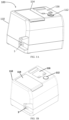
FIG. 1A is a front-top-left side perspective view of a compact cigarette manufacturing machine according to an exemplary embodiment. -
FIG. 1B is another front-top-left side perspective view of the compact cigarette manufacturing machine shown inFIG. 1A . -
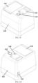
FIG. 1C is a front-top-right side perspective view of the compact cigarette manufacturing machine shown inFIGS. 1A-1B . -
FIG. 1D is a rear-top-right side perspective view of the compact cigarette manufacturing machine shown inFIGS. 1A-1C . -
FIG. 1E is a rear-top-left side perspective view of the compact cigarette manufacturing machine shown inFIGS. 1A-1D . -
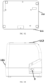
FIG. 1F is a top plan view of the compact cigarette manufacturing machine shown inFIGS. 1A-1E . -
FIG. 1G is a bottom plan view of the compact cigarette manufacturing machine shown inFIGS. 1A-1F . -
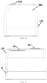
FIG. 1H is a left elevation view of the compact cigarette manufacturing machine shown inFIGS. 1A-1G . -
FIG. 1I is a right elevation view of the compact cigarette manufacturing machine shown inFIGS. 1A-1H . -
FIG. 1J is a front elevation view of the compact cigarette manufacturing machine shown inFIGS. 1A-1I . -
FIG. 1K is a rear elevation view of the compact cigarette manufacturing machine shown inFIGS. 1A-1J . -
FIG. 2 is a top view of the compact cigarette manufacturing machine shown inFIGS. 1A-1K , where a lid of the compact cigarette manufacturing machine is opened. -
FIG. 3 is a section view of the compact cigarette manufacturing machine across the plane A-A inFIG. 2 . -
FIG. 4 is a perspective view of the internal structure of a compact cigarette manufacturing machine shown inFIGS. 1A-1K ,2 , and3 . -
FIG. 5 is a perspective view of the internal structure of a compact cigarette manufacturing machine shown inFIGS. 1A-1K ,2 , and3 . -
FIG. 6 is a perspective view of the internal structure of a compact cigarette manufacturing machine shown inFIGS. 1A-1K ,2 , and3 . -
FIG. 7A is a perspective view of the assembly of a bracket, a push spoon, and a pusher according to an exemplary embodiment. -
FIG. 7B is a top view of a bracket shown inFIGS. 3-6 and7A . -
FIG. 7C is a side view of a bracket shown inFIGS. 3-6 ,7A, and 7B . -
FIG. 7D is a perspective view of a bracket shown inFIGS. 3-6 and7A-7C . -
FIG. 8 is a perspective view of a presser according to an exemplary embodiment. -
FIG. 9 is a bottom view of the internal structure of a compact cigarette manufacturing machine shown inFIGS. 1A-1K ,2 , and3 . - The invention now will be described more fully hereinafter through reference to various embodiments. These embodiments are provided so that this disclosure convey the scope of the invention to those skilled in the art. Indeed, the invention may be embodied in many different forms and should not be construed as limited to the embodiments set forth herein; rather, these embodiments are provided so that this disclosure will satisfy applicable legal requirements. As used in the specification, and in the appended claims, the singular forms "a", "an", and "the", include plural referents unless the context clearly dictates otherwise.
- Still further, while various alternative embodiments as to the various aspects, concepts and features of the invention - such as alternative materials, structures, configurations, methods, circuits, devices and components, software, hardware, control logic, alternatives as to form, fit and function, and so on-may be described herein, such descriptions are not intended to be a complete or exhaustive list of available alternative embodiments, whether presently known or later developed. Those skilled in the art may readily adopt one or more of the inventive aspects, concepts or features into additional embodiments and uses within the scope of the present invention even if such embodiments are not expressly disclosed herein. Additionally, even though some features, concepts or aspects of the invention may be described herein as being a preferred arrangement or method, such description is not intended to suggest that such feature is required or necessary unless expressly so stated. Still further, exemplary or representative values and ranges may be included to assist in understanding the present disclosure, however, such values and ranges are not to be construed in a limiting sense and are intended to be critical values or ranges only if so expressly stated. Parameters identified as "approximate" or "about" a specified value are intended to include both the specified value and values within 10% of the specified value, unless expressly stated otherwise. Further, it is to be understood that the drawings accompanying the present disclosure may, but need not, be to scale, and therefore may be understood as teaching various ratios and proportions evident in the drawings. Moreover, while various aspects, features and concepts may be expressly identified herein as being inventive or forming part of an invention, such identification is not intended to be exclusive, but rather there may be inventive aspects, concepts and features that are fully described herein without being expressly identified as such or as part of a specific invention, the invention instead being set forth in the appended claims. Descriptions of exemplary methods or processes are not limited to inclusion of all steps as being required in all cases, nor is the order that the steps are presented to be construed as required or necessary unless expressly so stated.
- Embodiments according to the present disclosure can be used for manufacturing cigarettes from filler material, such as cut tobacco, in small amounts. In addition to cut tobacco, embodiments according to the present disclosure can also be used for filling other materials, such as cut or ground products, into a cigarette tube. Cigarette manufacturing machines according to the present disclosure are compact in size, have simple mechanical structures, and require only simple operations such as depositing cut tobacco or other materials and activating a start switch. In addition, in small-scale operations, the cigarette manufacturing machines fully utilize the deposited materials with little waste, and pack the materials evenly and firmly in the cigarette tube as large-scale machines do.
- As illustrated in
FIGS. 1A-1K ,2 , and3 , in some embodiments, a compactcigarette manufacturing machine 100 comprises ahousing 4 enclosing amaterial chamber 40. Thematerial chamber 40 has a bottom orbase surface 42 and an open end 44 for receiving cut tobacco or other materials. The compactcigarette manufacturing machine 100 further comprises a fillingpipe 3 coupled with theouter casing 110. The fillingpipe 3 extends into a fillingcavity 31 below thematerial chamber 40 and in communication with thematerial chamber 40 through anopening 43 of thebottom surface 42. The compact cigarette manufacturing machine further comprises aloading element 2 assembled with thehousing 4 and slidable along thebottom surface 42. In operation, theloading element 2 loads or pushes the materials received in thematerial chamber 40 into the fillingcavity 31 through theopening 43 of thebottom surface 42. The compactcigarette manufacturing machine 100 further comprises apresser 1 assembled with thehousing 4 and operable to press or tamp the materials loaded in the fillingcavity 31. The compactcigarette manufacturing machine 100 may further comprise apusher 7 for compressing and packing the materials in the fillingcavity 31. The compactcigarette manufacturing machine 100 further comprises apush spoon 35 slidably disposed inside the fillingpipe 3. Thepush spoon 35 is operable to deliver materials in the fillingcavity 31 into a cigarette tube loaded on the filling tip of the fillingpipe 3. - The compact
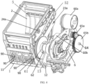
cigarette manufacturing machine 100 further comprises apower source 6 for driving the mechanical components. Thepower source 6 may comprise one or more electric motors for driving thepush spoon 35, thepusher 7, thepresser 1, and theloading element 2. As illustrated inFIGS. 4 and9 , thepower source 6 may comprise anelectric motor 60a, anelectric motor 60b, and anelectric motor 60c. Thepower source 6 may comprise anoutput shaft 62 attached with aneccentric disk 61. Theoutput shaft 62 is driven by an electric motor of thepower source 6. For example, as illustrated inFIG. 4 , theoutput shaft 62 is driven by theelectric motor 60b. Theeccentric disk 61 may be directly coupled to theoutput shaft 62, or be connected to theoutput shaft 62 through power transmission mechanisms such as timing belts, gears, and reducers. - In some embodiments, the compact
cigarette manufacturing machine 100 comprises more than one power source for driving different mechanical components. In some embodiments, one or more mechanical components are manually driven. - As illustrated in
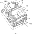
FIGS. 1A-1K , in some embodiments, the mechanical components of the compactcigarette manufacturing machine 100 are contained in anouter casing 110. Components for controlling the compactcigarette manufacturing machine 100, such as apower switch 111 and astart switch 112, may be disposed on a surface of theouter casing 110. As illustrated inFIGS. 1A-1K and2 , theouter casing 110 may include alid 114 facing the open end 44 of thematerial chamber 40. Thelid 114 may be pivotably attached to thecasing 110 and can be opened to allow the user to deposit cut tobacco or other materials into thematerial chamber 40, and can be closed to prevent the deposited materials from spilling out from thematerial chamber 40 or being contaminated during operation. - As illustrated in
FIGS. 2-4 , in some embodiments, thehousing 4 comprises thebottom surface 42 and vertical side walls. Thebottom surface 42 may have a variety of suitable shapes, and may for example, be ramped or angled to facilitate funneling of the tobacco or other filler material toward the fillingcavity 31. For example, thebottom surface 42 may be a curved surface as illustrated inFIG. 3 . In various embodiments, thebottom surface 42 may be a horizontal flat surface, or a sloping flat surface. Thehousing 4 encloses thematerial chamber 40. As illustrated inFIG. 4 , the housing may have an entirely open top portion defining the open end 44 for receiving cut tobacco or other materials. Alternatively, thehousing 4 may have one or more openings on the side walls or a top surface, for receiving the materials. As illustrated inFIG. 3 , theopening 43 to the fillingcavity 31 is formed on thebottom surface 42 of thehousing 4, from which materials can fall out of thematerial chamber 40. In some embodiments, thebottom surface 42 is a curved or sloping surface, and theopening 43 is formed at a lowest portion of thebottom surface 42. - Preferably, the
bottom surface 42 of thehousing 4 is a curved surface, allowing all of the materials to reach theopening 43, even when a small amount of materials is received in thematerial chamber 40, and facilitating rotary motion of theloading element 2 along thecurved bottom surface 42. Theopening 43 and the fillingcavity 31 are disposed proximate to each other in order to reduce the horizontal range of movement of theloading element 2. In addition, theloading element 2 may be accommodated in the upper portion of thematerial chamber 40. As result, thecigarette manufacturing machine 100 has a compact size suitable for domestic use. - As illustrated in
FIGS. 3 ,5 , and7A-7D , the compactcigarette manufacturing machine 100 may further comprise abracket 8 disposed beneath thehousing 4. Thebracket 8 comprises aslot 81. In some embodiments, as illustrated inFIG. 3 , theslot 81 and theopening 43 of thebottom surface 42 of thehousing 4 have substantially the same width, and theslot 81 is positioned below theopening 43. In other embodiments, theopening 43 is larger in width than theslot 81, such that the top surface of thebracket 8 defines a portion of thematerial chamber 40. - As illustrated in
FIG. 7A-7D , in some embodiments, thebracket 8 defines acavity 80 accommodating thepusher 7. In some embodiments, the fillingcavity 31 is defined within thecavity 80. In some embodiments, as illustrated inFIG. 7A ,7C, and 7D , thecavity 80 includes asemi-cylindrical recess 83 that is aligned with the fillingpipe 3 and defines at least a portion of the fillingcavity 31. - As illustrated in
FIGS. 3 and5 , the fillingcavity 31 is disposed beneath thematerial chamber 40. In some embodiments, the fillingpipe 3 extends into the fillingcavity 31. As illustrated inFIGS. 1A-1K , the fillingpipe 3 extends out of theouter casing 110, such that a cigarette tube to be filled can be loaded on the filling tip of the fillingpipe 3. - The
push spoon 35 is operable to deliver tobacco or other materials in the fillingcavity 31 into a cigarette tube loaded on the filling tip of the fillingpipe 3. As illustrated inFIG. 7A , thepush spoon 35 is slidably disposed inside the fillingcavity 31, and may include a hollow recess for carrying the materials in the fillingcavity 31. Thepush spoon 35 is operable to slide within the fillingcavity 31 toward the cigarette tube, carry the materials into the cavity of the cigarette tube, deposit the materials, and slide back into the fillingcavity 31. In some embodiments, thepush spoon 35 is operable to move in reciprocating motion. Thepush spoon 35 may be driven manually, or by thepower source 6 or another power source. For example, as illustrated inFIG. 9 , thepush spoon 35 may be mechanically coupled to theelectric motor 60c of thepower source 6 through aswing arm 32. In some embodiments, the fillingcavity 31 and thepush spoon 35 may be configured according to the tobacco cavity and the push spoon assembly disclosed inU.S. Patent Application No. 2020/0281251 . - As illustrated in
FIGS. 1A-1K ,6 , and9 , the fillingpipe 3 is a substantially cylindrical tube and is coupled with theouter casing 110. The end portion or filling tip of the fillingpipe 3 is configured to be received or inserted into the cigarette tube to be filled. The cigarette tube loaded on the filling tip may be held in place by friction with the fillingpipe 3. The cigarette tube may also be held in place manually by the user, or by a clip disposed at the filling tip . In some embodiments, the compactcigarette manufacturing machine 100 comprises a buckling assembly for pressing the cigarette tube against the fillingpipe 3 while materials are being filled into the cigarette tube, and releasing the cigarette tube after the materials are filled. In some embodiments, the buckling assembly may be configured according to the paper buckling assembly disclosed inU.S. Patent Application No. 2020/0281251 . - The compact
cigarette manufacturing machine 100 further comprises apusher 7. As illustrated inFIG. 5 , thepusher 7 is disposed below thematerial chamber 40 and is operable to move horizontally toward or away from thepush spoon 35 in reciprocating motion, in order to compress the loose cut tobacco or other materials. In some embodiments, thepusher 7 is slidably disposed in thecavity 80 defined by thebracket 8. Theexemplary pusher 7 is an elongated plate having aconcave tip 75 facing thepush spoon 35. As illustrated inFIG. 7A , in some embodiments, thepush spoon 35 has ahorizontal side opening 34 facing thepusher 7, and the fillingcavity 31 extends between thepush spoon 35 and theconcave tip 75 of thepusher 7. As illustrated inFIGS. 3 and5 , thepusher 7 is operable to reach at least theopening 43 of thebottom surface 42 of thehousing 4, in order to compress and pack the materials in the fillingcavity 31. In some embodiments, thepusher 7 is operable to reach a maximum range toward the fillingpipe 3 where theconcave tip 75 defines a cylindrical space with thesemi-cylindrical recess 83 of thecavity 80, such that thepush spoon 35 can pack the cylindrical mass of materials into the fillingpipe 3. - In some embodiments, as illustrated in
FIG. 7A , ablade 36 for cutting tobacco or other materials is formed on the lower edge of thepush spoon 35 facing the fillingcavity 31. Theblade 36 may be formed on the upper edge and/or the lower edge of thepush spoon 35 facing the fillingcavity 31. In some embodiments, theblade 36 is disposed on the top edge of theconcave tip 75 of thepusher 7. Theblade 36 may also be disposed on the bottom edge of theconcave tip 75 of thepusher 7. In some embodiments, theblade 36 is oriented in the horizontal direction and facing the fillingcavity 31. In some embodiments, theblade 36 is disposed on an edge of theslot 81 of thebracket 8, and is oriented in the horizontal direction and facing thepusher 7. When thepusher 7 moves toward thepush spoon 35, theblade 36 cuts across the loose materials hanging over the edge of the fillingcavity 31. As result, the mass of cut tobacco or other materials after compression has a smooth surface, without excess materials on the surface which may interfere with the steps that follow, such as filling the materials into the cigarette tube. - The movement of the
pusher 7 is driven by thepower source 6 through a power transmission mechanism. In some embodiments, as illustrated inFIG. 7A , the power transmission mechanism for thepusher 7 comprises ashaft 64, acam 71 coupled to theshaft 64, and atransmission plate 72. Theshaft 64 is mechanically coupled to and driven by an electric motor of thepower source 6. For example, as illustrated inFIGS. 4 and5 , theshaft 64 is driven by theelectric motor 60a throughgearwheels - The
transmission plate 72 is coupled with thepusher 7 through apin 76. The rotation of theshaft 64 drives the horizontal movement of thetransmission plate 72 through thecam 71, causing the horizontal movement of thepusher 7. - The
pusher 7 may be an integrally formed component, or comprise two or more connected components. In some embodiments, as illustrated inFIG. 7A , thepusher 7 comprises afirst connector 73 for coupling with thetransmission plate 72 and asecond connector 74 partially defining the fillingcavity 31. Thefirst connector 73 and thesecond connector 74 may be affixed to each other, or coupled to each other through mechanical transmission, such that the horizontal movement of thefirst connector 73 drives the horizontal movement of thesecond connector 74. - The filling
cavity 31 has an open top end aligned with theopening 43 on thebottom surface 42 of thehousing 4, such that all materials falling through theopening 43 falls into the fillingcavity 31. - As illustrated in
FIG. 3 , theloading element 2 is assembled with thehousing 4 and is operable to slide along thebottom surface 42. In some embodiments, theloading element 2 is operable to move in reciprocating rotary motion. Theloading element 2 may have various suitable shapes that fit with thebottom surface 42, in order to prevent cut tobacco or other materials from entering the space in between. For example, as illustrated inFIG. 3 , thebottom surface 42 may be a curved surface, and theloading element 2 may have a curved shape that fits with thebottom surface 42. In some embodiments, thebottom surface 42 is formed with slide rails, and theloading element 2 is slidably assembled on the slide rails. In other embodiments, theloading element 2 is slidably coupled with a slit formed on thebottom surface 42 or a side wall of the housing. - In some embodiments, as illustrated in
FIG. 3 , the front edge of theloading element 2 comprises a narrow, taperedsurface 21. The narrow, taperedsurface 21 allows theloading element 2 to smoothly pass through the materials on the bottom surface of thehousing 4 with limited resistance, with the narrow front end depositing a limited amount of materials into the fillingcavity 31. In addition, the taperedsurface 21 allows the materials to spread over, and form a thin layer, on the top surface of theloading element 2. As result, only a small amount of materials falls into the fillingcavity 31 each time theloading element 2 slides down. As such, thepresser 1 only presses a small amount of materials loaded in the fillingcavity 31 each time thepresser 1 swings down, as small portions of materials enter the fillingcavity 31 successively. This prevents the materials from excessively accumulating at one portion of the fillingcavity 31 while not adequately filling other portions, which ensures that the materials are packed firmly and evenly in the fillingcavity 31. - In some embodiments, the
loading element 2 is coupled to a pivot affixed to thehousing 4 through a swing arm. In other embodiments, as illustrated inFIGS. 4-6 , theloading element 2 is coupled to a pair ofpivots housing 4, respectively through a pair ofswing arms FIGS. 4-6 , the pair of pivots and the pair of swing arms are disposed outside thehousing 4, and theloading element 2 is coupled to the pair of swing arms through a slit formed along thebottom surface 42 of thehousing 4. In various embodiments, each of the pivots and each of the swing arms may be disposed within or outside thehousing 4. - As illustrated in
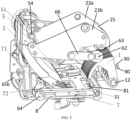
FIGS. 4-6 , theloading element 2 may be operable to swing about thepivots swing arms FIG. 4 , theswing arms housing 4 through thepivots swing arms loading element 2 and is operable to swing about thepivots FIG. 5 , theswing arms rod 25. In some embodiments, the swing arms are directly connected to thepower source 6, in order to drive the movement of theloading element 2. As illustrated inFIG. 5 , theswing arm 23b may be connected to aneccentric disk 63 provided on theoutput shaft 62 of thepower source 6 through alever 66. As such, the upward and downward sliding movements of theloading element 2 along thebottom surface 42 of thehousing 4 are driven through theswing arm 23b and thelever 66. In some embodiments, theswing arms loading element 2. - In some embodiments, the swing arms are indirectly driven by the
power source 6 through other mechanical components. - In some embodiments, the
loading element 2 is coupled to a shaft extending across thehousing 4, through a swing arm or a pair of swing arms. - In some embodiments, the
loading element 2 is directly driven by thepower source 6 through power transmission mechanisms. For example, thebottom surface 42 of thehousing 4 may comprise a slit, and the power transmission mechanisms may be coupled with theloading element 2 through the slit. In some embodiments, theloading element 2 comprises engagement slots (not shown) at the bottom surface, and the engagement slots engages with an engagement disk (not shown) rotatably assembled to thebottom surface 42 of thehousing 4. The engagement disk may be coupled to thepower source 6 and have an eccentric shape, such that the rotation of the engagement disk drives the movement of theloading element 2. Theloading element 2 may comprise two or more sets of engagement slots for engaging with two or more engagement disks disposed along a horizontal line and having different eccentricities. As such, theloading element 2 is operable in one direction in multiple steps. For example, theloading element 2 may be operable to move back and forth along thebottom surface 42 of thehousing 4 in one step or multiple steps. - In some embodiments, the
loading element 2 is driven by an engagement disk through a connecting rod (not shown) and a drive rod (not shown). The engagement disk is directly driven by thepower source 6 and has an eccentric shape. The engagement disk is coupled with the connecting rod and drives the movement of the connecting rod. The connecting rod has a rotating end coupled with the drive rod through an eccentric disk and gearwheels. The drive rod is coupled with theloading element 2 and drives the reciprocating motion of theloading element 2 within a predetermined range. Theloading element 2 may also be mechanically coupled with thepower source 6 through any suitable arrangement, including, for example, one or more motors and screws. - In some embodiments, the
loading element 2 is mounted on a sliding block operable along a guide rail on thebottom surface 42 of thehousing 4. In other embodiments, theloading element 2 may be driven by one or more swing arms, which may provide a simpler and more compact mechanical structure, as illustrated inFIGS. 4-6 . Such an arrangement may also reduce exposure of the moving components (e.g.,power source 6 components) to contamination by tobacco/material entrapment in gaps or spaces in the loading element arrangement. - The
presser 1 comprises apress surface 14 for contacting with and pressing the cut tobacco or other materials. Thepresser 1 may have a variety of suitable shapes. For example, as illustrated inFIG. 5 , thepresser 1 may be fan-shaped with a cutout, and assembled with thehousing 4 through ashaft 12. In the embodiment illustrated inFIG. 5 , thepresser 1 is operable to swing about theshaft 12 between a withdrawn position and a pressing position. In some embodiments, thepresser 1 is operable to move in reciprocating motion. When thepresser 1 moves from the withdrawn position toward the pressing position, thepress surface 14 moves squarely toward the fillingcavity 31, in order to firmly pack materials into the fillingcavity 31. At the withdrawn position, as illustrated inFIG. 5 , thepress surface 14 is above the bottom of thematerial chamber 40, allowing materials to enter the fillingcavity 31 from thematerial chamber 40. - As illustrated in
FIGS. 3 and6 , aside panel 46 may be provided in thehousing 4 to define a side portion of thematerial chamber 40. As illustrated inFIG. 3 , thepresser 1 may be disposed behind theside panel 46, such that thepresser 1 is substantially outside thematerial chamber 40 at the withdrawn position and the pressing position. - As illustrated in
FIG. 4 , the compactcigarette manufacturing machine 100 may further comprise aswing arm 13 for driving the swinging motion of thepresser 1. In some embodiments, one end of theswing arm 13 is eccentrically connected to theoutput shaft 62 of thepower source 6, and the other end is connected to thepresser 1. For example, as illustrated inFIGS. 4 and5 , theswing arm 13 may have one end connected to theeccentric disk 61 provided on theoutput shaft 62, and the other end connected to thepresser 1 through theshaft 12 provided in theshaft hole 15. In some embodiments, theswing arm 13 is connected to thepower source 6 at an upper portion and connected to thepresser 1 at a lower portion. In other embodiments, theswing arm 13 is connected to thepower source 6 at a lower portion and connected to thepresser 1 at an upper portion. Thepower source 6 causes the relative movement of the two ends of theswing arm 13, driving thepresser 1 to swing back and forth in an arc trajectory. In some embodiments, theswing arm 13 has a bent portion for limiting the movement range of thepresser 1. - As illustrated in
FIGS. 3 ,4 , and9 , in some embodiments, atorsion spring 11 is provided at theshaft 12. Thetorsion spring 11 provides a recovery force for thepresser 1 to return from the pressing position to the withdrawn position, such that quick reciprocating motion of pressing the cut tobacco or other materials can be achieved. In some embodiments, the recovery force is provided by thetorsion spring 11, so that the movement of thepresser 1 from the pressing position to the withdrawn position is not driven by thepower source 6. - In some embodiments, the
presser 1 and theloading element 2 are connected through a connection arm in order to operate cooperatively. With the connection arm, the vertical reciprocating motion of thepresser 1 and the horizontal reciprocating motion of theloading element 2 can be driven by a single power source. For example, thepresser 1 may start moving from the withdrawn position toward the pressing position to firmly pack materials into the fillingcavity 31, when the front edge of theloading element 2 reaches theopening 43 of thebottom surface 42 of thehousing 4. - As illustrated in
FIGS. 2 and4-6 , the compactcigarette manufacturing machine 100 may further comprise one ormore stir bars 5 assembled within thehousing 4. Thestir bar 5 is operable to swing or rotate in order to agitate the materials received in thematerial chamber 40, for example by slapping the inner surface of theloading element 2 ormaterial chamber 40. This movement of thestir bar 5 evens the distribution of materials in thematerial chamber 40 and prevents materials from remaining (e.g., becoming caked or solidified) on thematerial chamber 40 and/orloading element 2. As illustrated inFIG. 5 , thestir bar 5 may be assembled to ashaft 54. Atorsion spring 51 may be attached to theshaft 54 for providing a recovery force when thestir bar 5 swings or rotates, in order to increase the strength and speed of stirring. Thestir bar 5 may be driven by the power transmission mechanism for theloading element 2, or by an independent power transmission mechanism. As illustrated inFIG. 4 , thestir bar 5 may be driven by aswing arm 52 through theshaft 54, where theswing arm 52 is connected to theeccentric disk 61 provided on theoutput shaft 62 of thepower source 6. - The compact
cigarette manufacturing machine 100 may further comprise an electric control system comprising acontrol panel 116 and acircuit board 118. The circuit board is connected with a microcontroller for controlling thepower source 6 of the mechanical components. In some embodiments, the microcontroller is capable of receiving data and controlling electric circuits, such as receiving data about the displacement of thepresser 1, theloading element 2, and thepush spoon 35, and start or stop the power output from the one or more power source. The microcontroller may be, for example, a main control module of a computing device. The control panel controls thepower source 6 through connection with the circuit board. - In some embodiments, the compact
cigarette manufacturing machine 100 further comprisessensors 90 and components providing signals for thesensors 90, in order to determine the displacement of thepresser 1, theloading element 2, and thepush spoon 35. Thesensors 90 and the components providing signals may be provided on thepresser 1, theloading element 2, and thepush spoon 35, or on other components of the compactcigarette manufacturing machine 100. Thesensors 90 send the microcontroller data representing the displacement of the components in order to control the operation of the compactcigarette manufacturing machine 100. For example, the microcontroller determines whether the fillingcavity 31 is fully packed with cut tobacco or other materials based on the displacement of thepresser 1, and controls thepresser 1 to continue or stop operating. - As illustrated in
FIGS. 3-5 , in some embodiments, thesensors 90 coordinate with thetorsion spring 11 provided at theshaft 12 to determine the displacement of thepresser 1. Thepresser 1 may comprise one or more independently movable presser units. In some embodiments, thesensors 90 are provided to determine the displacement of each of the more than one presser units. For example, as illustrated inFIGS. 4 and8 , thepresser 1 may comprise four presser units, and each of the pressor units comprises asensor 90 and atorsion spring 11 for determining the displacement of the corresponding presser unit. As such, when thepresser 1 moves toward the pressing position to pack materials into the fillingcavity 31, the amount of materials under each of the four presser units can be individually determined by thesensors 90. As compared with the configuration with only one pressor unit, providing two or more pressor units allows the compactcigarette manufacturing machine 100 to continue packing materials into the fillingcavity 31 until each portion of the fillingcavity 31 is fully packed, when each of thesensors 90 detects at least a predetermined amount of materials under each of the presser units. In addition, the more than onetorsion spring 11 may individually adjust the pressing position of each of the pressor units, such that each portion of the fillingcavity 31 can be fully packed even if the materials are unevenly distributed in thematerial chamber 40. - In operation, the
lid 114 is opened and the user deposits cut tobacco or other materials to be processed in thehousing 4. A cigarette tube is loaded onto the filling tip of the fillingpipe 3 coupled with theouter casing 110. The power is switched on (e.g., by depressing thepower switch 111 and the start switch 112), and thepower source 6 first drives the movement of thepresser 1, theloading element 2, and thestir bar 5. Theloading element 2 pushes the materials along thebottom surface 42, and the materials falls into the fillingcavity 31 through theopening 43 of thebottom surface 42. Thepresser 1 moves between the withdrawn position and the pressing position to firmly pack the materials into the fillingcavity 31. In some embodiments, thepresser 1 comprises multiple presser units havingmultiple sensors 90 for determining the amount of materials under each of the presser units. Thesensors 90 transmit data representing the amount of materials under each of the presser units to the microcontroller. When one or more of thesensors 90 indicates that the amount of tobacco/material in the fillingcavity 31 is insufficient (e.g., based on the degree of rotation of one or more presser unit), theloading element 2 and thepresser 1 repeat their reciprocating movement (as controlled by the microcontroller) to load and press additional tobacco/material into the filling cavity. When the amount of materials under each of the presser units reaches a predetermined amount, the microcontroller stops the movement of thepresser 1, theloading element 2, and thestir bar 5. Next, the microcontroller controls thepusher 7 to move toward thepush spoon 35, pressing against the materials packed in the fillingcavity 31. When thepusher 7 reaches the maximum range toward thepush spoon 35, the materials are formed into a cylindrical mass aligned with the fillingpipe 3. Lastly, the microcontroller controls thepush spoon 35 to deliver the tobacco or other materials into the cigarette tube. The microcontroller also controls thepusher 7 to move away from thepush spoon 35. The above process can be repeated until the power is switched off.
Claims (15)
- A compact cigarette manufacturing machine (100) comprising:a housing (4) enclosing a material chamber (40), the material chamber (40) having a bottom surface (42) and an open end (44) for receiving materials to be filled in a cigarette tube;a filling pipe (3) disposed on the housing (4) to define a filling tip, wherein the filling pipe (3) extends into a filling cavity (31), wherein the filling cavity (31) is in communication with the material chamber (40) through an opening (43) of the bottom surface (42) of the material chamber (40);a loading element (2) assembled with the housing (4) and slidable along the bottom surface (42) of the material chamber (40), wherein the loading element (2) is operable to load the materials into the filling cavity (31) through the opening (43) of the bottom surface (42);a pusher (7) disposed below the material chamber (40) and operable to move horizontally toward or away form the push spoon (35) in order to compress the materials,characterized bya push spoon (35) slidably disposed inside the filling cavity (31), wherein the push spoon (35) is operable to deliver the materials in the filling cavity (31) into the cigarette tube when the cigarette tube is loaded on the filling tip; and a presser (1) assembled with the housing (4) and operable to press the materials loaded in the filling cavity (31).
- The compact cigarette manufacturing machine (100) according to claim 1, wherein the bottom surface (42) of the material chamber (40) is a curved surface.
- The compact cigarette manufacturing machine (100) according to claim 1, wherein the compact cigarette manufacturing machine (100) further comprises a power source (6) for driving the operation of the pusher (7), wherein the push spoon (35) has a horizontal opening facing the pusher (7), and wherein the pusher has a concave tip (75) facing the push spoon (35).
- The compact cigarette manufacturing machine (100) according to claim 1, wherein the compact cigarette manufacturing machine (100) further comprises a power source (6) for driving the operation of at least one of the push spoon (35), the presser (1), and the loading element (2).
- The compact cigarette manufacturing machine (100) according to claim 1, wherein the presser (1) and the loading element (2) operate cooperatively by connection through a connection arm.
- The compact cigarette manufacturing machine (100) according to claim 3, further comprising a bracket (8) defining a cavity (80) accommodating the pusher (7) and defining at least a portion of the filling cavity (31), wherein the bracket (8) comprises a slot (81) for communicating the material chamber (40) and the filling cavity (31).
- The compact cigarette manufacturing machine (100) according to claim 1, wherein the presser (1) is operable to swing about a shaft (12) between a withdrawn position and a pressing position, and wherein a press surface (14) of the presser (1) moves squarely toward the filling cavity (31) for firmly packing the materials into the filling cavity (31) when the presser (1) moves from the withdrawn position toward the pressing position.
- The compact cigarette manufacturing machine (100) according to claim 3, further comprising a blade (36) formed on an edge of the push spoon (35) facing the filling cavity (31).
- The compact cigarette manufacturing machine (100) according to claim 6, further comprising a blade (36) disposed on a top edge of the pusher (7) and/or an edge of the slot (81) of the bracket (8), wherein the blade (36) is oriented horizontally and facing the filling cavity (31).
- The compact cigarette manufacturing machine (100) according to claim 1, wherein the presser (1) is disposed substantially outside the material chamber (40).
- The compact cigarette manufacturing machine (100) according to claim 1, wherein the compact cigarette manufacturing machine (100) further comprises at least one stir bar (5) assembled within the housing (4), wherein the at least one stir bar (5) is operable to swing or rotate in order to agitate the materials in the material chamber (40), and wherein the at least one stir bar (5) is driven by a power source (6) through an eccentric disk (61).
- The compact cigarette manufacturing machine (100) according to claim 1, wherein a front edge of the loading element (2) comprises a tapered surface (21).
- The compact cigarette manufacturing machine (100) according to claim 1, wherein the compact cigarette manufacturing machine (100) further comprises one or more sensors (90) for determining the displacement of at least one of the presser (1), the loading element (2), and the push spoon (35).
- The compact cigarette manufacturing machine (100) according to claim 1, wherein the presser (1) comprises two or more presser units, and wherein each of the two or more presser units comprises a sensor (90) and a torsion spring (11) configured to determine the displacement of each of the two or more presser units.
- A method for filling a cigarette tube, comprising:receiving materials in a housing (4) enclosing a material chamber (40), the material chamber (40) having a bottom surface (42) and an open end (44);loading, by a loading element (2), the materials through an opening (43) of the bottom surface (42) into a filling cavity (31) beneath the housing (4),wherein the filling cavity (31) is in communication with the material chamber (40) through the opening (43) of the bottom surface (42) of the material chamber (40);wherein the loading element (2) is assembled with the housing (4) and slidable along the bottom surface (42) of the material chamber (40), compressing the materials by a pusher (7) disposed below the material chamber (4) and operable to move horizontally toward or away from the push spoon (35) in reciprocating motion,and characterised bypressing the materials loaded in the filling cavity (31) by a presser (1) assembled with the housing
anddelivering the materials into the cigarette tube by a push spoon (35).
Applications Claiming Priority (2)
| Application Number | Priority Date | Filing Date | Title |
|---|---|---|---|
| CN202011342877.0A CN112425815B (en) | 2020-11-25 | 2020-11-25 | Household small-sized cigarette making equipment |
| US17/319,680 US11771129B2 (en) | 2020-11-25 | 2021-05-13 | Compact cigarette manufacturing machine |
Publications (2)
| Publication Number | Publication Date |
|---|---|
| EP4005404A1 EP4005404A1 (en) | 2022-06-01 |
| EP4005404B1 true EP4005404B1 (en) | 2024-03-27 |
Family
ID=77447783
Family Applications (1)
| Application Number | Title | Priority Date | Filing Date |
|---|---|---|---|
| EP21192575.5A Active EP4005404B1 (en) | 2020-11-25 | 2021-08-23 | Cigarette manufacturing machine and method |
Country Status (2)
| Country | Link |
|---|---|
| US (1) | US20230380477A1 (en) |
| EP (1) | EP4005404B1 (en) |
Family Cites Families (3)
| Publication number | Priority date | Publication date | Assignee | Title |
|---|---|---|---|---|
| ATE386447T1 (en) * | 2002-11-21 | 2008-03-15 | Cousins Distributing Inc | DEVICE FOR FILLING A CIGARETTE TUBE WITH A MEASURED QUANTITY OF TOBACCO |
| US20110056504A1 (en) * | 2009-09-04 | 2011-03-10 | Jacques Laplante | Cigarette blank filling tube apparatus |
| US20200281251A1 (en) | 2019-03-08 | 2020-09-10 | Jian Dong Liu | Cigarette manufacturing machine |
-
2021
- 2021-08-23 EP EP21192575.5A patent/EP4005404B1/en active Active
-
2023
- 2023-08-11 US US18/448,763 patent/US20230380477A1/en active Pending
Also Published As
| Publication number | Publication date |
|---|---|
| US20230380477A1 (en) | 2023-11-30 |
| EP4005404A1 (en) | 2022-06-01 |
Similar Documents
| Publication | Publication Date | Title |
|---|---|---|
| US20220160019A1 (en) | Compact cigarette manufacturing machine | |
| JP4279783B2 (en) | Device for filling a tobacco tube with a measured amount of tobacco leaves | |
| JP4713585B2 (en) | Dosing device for feeding leachable products | |
| EP4005404B1 (en) | Cigarette manufacturing machine and method | |
| EP2257193B1 (en) | Apparatus for filling cigarette tubes with tobacco | |
| US3688471A (en) | Bag hanger | |
| US2311011A (en) | Cigar machine long-filler feed | |
| AU2012236960A1 (en) | Cigarette making machine | |
| US20120240945A1 (en) | Cigarette making machine | |
| WO2012051694A1 (en) | High speed cigarette manufacturing machine | |
| WO2012167369A1 (en) | Cigarette manufacturing apparatus | |
| CN111513357A (en) | Automatic making and selling equipment for food containing stuffing | |
| CN201010051Y (en) | Warming packing machine | |
| CN213939704U (en) | Household small cigarette making equipment | |
| CN211861656U (en) | Stuffing discharging machine capable of selectively discharging stuffing | |
| CN211861652U (en) | Automatic equipment of selling of food of multiple filling of preparation | |
| CN211861653U (en) | Automatic making and selling equipment for various foods containing stuffing | |
| CN211672385U (en) | Automatic making and selling equipment for food containing stuffing | |
| CN211672175U (en) | Go out filling operation structure convenient to change filling pocket | |
| KR20190032920A (en) | Apparatus for manufacturing cigarette | |
| CN211861651U (en) | Stuffing discharging machine for making food with multiple stuffing materials | |
| CN211349481U (en) | Bag placing mechanism of stuffing discharging machine | |
| GB2024089A (en) | Machine for forming lollies | |
| CN211861771U (en) | Stuffing discharging machine | |
| US20120240947A1 (en) | Cigarette making machine with pivot pin connector |
Legal Events
| Date | Code | Title | Description |
|---|---|---|---|
| PUAI | Public reference made under article 153(3) epc to a published international application that has entered the european phase |
Free format text: ORIGINAL CODE: 0009012 |
|
| STAA | Information on the status of an ep patent application or granted ep patent |
Free format text: STATUS: REQUEST FOR EXAMINATION WAS MADE |
|
| 17P | Request for examination filed |
Effective date: 20210823 |
|
| AK | Designated contracting states |
Kind code of ref document: A1 Designated state(s): AL AT BE BG CH CY CZ DE DK EE ES FI FR GB GR HR HU IE IS IT LI LT LU LV MC MK MT NL NO PL PT RO RS SE SI SK SM TR |
|
| RBV | Designated contracting states (corrected) |
Designated state(s): AL AT BE BG CH CY CZ DE DK EE ES FI FR GB GR HR HU IE IS IT LI LT LU LV MC MK MT NL NO PL PT RO RS SE SI SK SM TR |
|
| RIC1 | Information provided on ipc code assigned before grant |
Ipc: A24C 5/06 20060101AFI20230829BHEP |
|
| GRAP | Despatch of communication of intention to grant a patent |
Free format text: ORIGINAL CODE: EPIDOSNIGR1 |
|
| STAA | Information on the status of an ep patent application or granted ep patent |
Free format text: STATUS: GRANT OF PATENT IS INTENDED |
|
| INTG | Intention to grant announced |
Effective date: 20231016 |
|
| GRAS | Grant fee paid |
Free format text: ORIGINAL CODE: EPIDOSNIGR3 |
|
| GRAA | (expected) grant |
Free format text: ORIGINAL CODE: 0009210 |
|
| STAA | Information on the status of an ep patent application or granted ep patent |
Free format text: STATUS: THE PATENT HAS BEEN GRANTED |
|
| AK | Designated contracting states |
Kind code of ref document: B1 Designated state(s): AL AT BE BG CH CY CZ DE DK EE ES FI FR GB GR HR HU IE IS IT LI LT LU LV MC MK MT NL NO PL PT RO RS SE SI SK SM TR |
|
| REG | Reference to a national code |
Ref country code: GB Ref legal event code: FG4D |
|
| REG | Reference to a national code |
Ref country code: CH Ref legal event code: EP |
|
| REG | Reference to a national code |
Ref country code: DE Ref legal event code: R096 Ref document number: 602021010868 Country of ref document: DE |