EP4004631B1 - System for 3d pose measurement with high precision and real-time object tracking - Google Patents
System for 3d pose measurement with high precision and real-time object tracking Download PDFInfo
- Publication number
- EP4004631B1 EP4004631B1 EP20843746.7A EP20843746A EP4004631B1 EP 4004631 B1 EP4004631 B1 EP 4004631B1 EP 20843746 A EP20843746 A EP 20843746A EP 4004631 B1 EP4004631 B1 EP 4004631B1
- Authority
- EP
- European Patent Office
- Prior art keywords
- vision
- structured
- laser
- stereo
- module
- Prior art date
- Legal status (The legal status is an assumption and is not a legal conclusion. Google has not performed a legal analysis and makes no representation as to the accuracy of the status listed.)
- Active
Links
Images




Classifications
-
- G—PHYSICS
- G01—MEASURING; TESTING
- G01B—MEASURING LENGTH, THICKNESS OR SIMILAR LINEAR DIMENSIONS; MEASURING ANGLES; MEASURING AREAS; MEASURING IRREGULARITIES OF SURFACES OR CONTOURS
- G01B11/00—Measuring arrangements characterised by the use of optical techniques
- G01B11/24—Measuring arrangements characterised by the use of optical techniques for measuring contours or curvatures
- G01B11/25—Measuring arrangements characterised by the use of optical techniques for measuring contours or curvatures by projecting a pattern, e.g. one or more lines, moiré fringes on the object
- G01B11/2545—Measuring arrangements characterised by the use of optical techniques for measuring contours or curvatures by projecting a pattern, e.g. one or more lines, moiré fringes on the object with one projection direction and several detection directions, e.g. stereo
-
- H—ELECTRICITY
- H04—ELECTRIC COMMUNICATION TECHNIQUE
- H04N—PICTORIAL COMMUNICATION, e.g. TELEVISION
- H04N13/00—Stereoscopic video systems; Multi-view video systems; Details thereof
- H04N13/30—Image reproducers
- H04N13/363—Image reproducers using image projection screens
-
- G—PHYSICS
- G01—MEASURING; TESTING
- G01B—MEASURING LENGTH, THICKNESS OR SIMILAR LINEAR DIMENSIONS; MEASURING ANGLES; MEASURING AREAS; MEASURING IRREGULARITIES OF SURFACES OR CONTOURS
- G01B11/00—Measuring arrangements characterised by the use of optical techniques
- G01B11/24—Measuring arrangements characterised by the use of optical techniques for measuring contours or curvatures
- G01B11/245—Measuring arrangements characterised by the use of optical techniques for measuring contours or curvatures using a plurality of fixed, simultaneously operating transducers
-
- G—PHYSICS
- G02—OPTICS
- G02B—OPTICAL ELEMENTS, SYSTEMS OR APPARATUS
- G02B27/00—Optical systems or apparatus not provided for by any of the groups G02B1/00 - G02B26/00, G02B30/00
- G02B27/48—Laser speckle optics
-
- G—PHYSICS
- G06—COMPUTING OR CALCULATING; COUNTING
- G06T—IMAGE DATA PROCESSING OR GENERATION, IN GENERAL
- G06T7/00—Image analysis
- G06T7/50—Depth or shape recovery
- G06T7/521—Depth or shape recovery from laser ranging, e.g. using interferometry; from the projection of structured light
-
- H—ELECTRICITY
- H04—ELECTRIC COMMUNICATION TECHNIQUE
- H04N—PICTORIAL COMMUNICATION, e.g. TELEVISION
- H04N13/00—Stereoscopic video systems; Multi-view video systems; Details thereof
- H04N13/20—Image signal generators
- H04N13/296—Synchronisation thereof; Control thereof
Definitions
- This disclosure is generally related to machine-vision systems. More specifically, this disclosure is related to a machine-vision system capable of performing three-dimensional (3D) pose measurement with high precision and real-time object tracking.
- Computer vision is a field of artificial intelligence (AI) that trains computers to interpret and understand the visual world.
- AI artificial intelligence
- machines can accurately identify and position objects.
- Industrial automation and robot-assisted manufacturing are increasingly using such technologies to improve their factory throughput and flexibility to respond efficiently to customers' needs and desires, as well as to maximize yield.
- a high-definition camera can detect details that human eyes cannot, and a fast computer processor can interpret the images and perform various complicated tasks of inspection and assembly (e.g., object recognition, micron-level crack detection, surface-defect detection, etc.) as fast as a human brain, but with a much higher repeatability and accuracy.
- US2011/037953A1 in an abstract states that "The present invention provides a projection display comprising an illumination system comprising at least one laser source unit and configured and operable for producing one or more light beams; a spatial light modulating (SLM) system accommodated at output of the illumination system and comprising one or more SLM units for modulating light incident thereon in accordance with image data; and a light projection optics for imaging modulated light onto a projection surface.
- SLM spatial light modulating
- the illumination system comprises at least one beam shaping unit comprising a Dual Micro-lens Array (DMLA) arrangement formed by front and rear micro-lens arrays (MLA) located in front and rear parallel planes spaced-apart along an optical path of light propagating towards the SLM unit, the DMLA arrangement being configured such that each lenslet of the DMLA directs light incident thereon onto the entire active surface of the SLM unit, each lenslet having a geometrical aspect ratio corresponding to an aspect ratio of said active surface of the SLM unit.”
- DMLA Dual Micro-lens Array
- MSA micro-lens arrays
- the invention relates to the laser display technology field and particularly discloses an RGB three color laser light source projection system in order to solve problems of a speckle effect and non-uniformity in laser projection display and a problem that three-color laser coupling is too complicated.
- the RGB three-color laser light source projection system comprises an RGB array laser light source module, an X type coupler, a beam shrinkage lens set, a homogenization and speckle elimination device, a shaping lens set, a TIR prism, a DLP modulator and a projection lens.
- the volume of the RGB three-color laser light source module is reduced through optimizing structures of the RGB array laser light source module and an X type coupler, and the cost is reduced.
- the homogenization and speckle elimination device is utilized to successfully solve problems of uniformity and speckles of the RGB three-color laser display.
- the RGB three color laser light source projection system is applicable toa projection system like a projector.”
- the invention discloses a laser speckle optical path and a laser projection light source system, and relates to the technical field of laser display.
- the system comprises a diffusion assembly and a lens assembly used for collimation and spotlight, the diffusion assembly is composed of at least two diffusion parts, wherein one of the diffusion parts is a dynamic speckle device, the other diffusion parts are static speckle devices, and the movement mode of the dynamic speckle device is cyclical rotation; and the lens assembly is arranged among the diffusion parts.
- the laser speckle optical path and the laser projection light source system have the advantages that better speckle and facula homogenization functions can be achieved through the combined use of the dynamic diffusion assembly and static diffusion assemblies; the laser beams are diverged and collimated repeatedly to greatly reduce the spatial coherence of the laser beams, thereby effectively solving the problem of speckle; the laser speckle optical path is simple in structure and small is size, and can be integrated easily in a laser display system to make the structure of an x ray machine more compact.”
- a respective stereo-vision module can include a structured-light projector, a first camera positioned on a first side of the structured-light projector, and a second camera positioned on a second side of the structured-light projector.
- the first and second cameras are configured to capture images of an object under illumination by the structured-light projector.
- the structured-light projector can include a laser-based light source and an optical modulator configured to reduce speckles caused by the laser-based light source.
- the optical modulator can further include a straight or curved light tunnel.
- the optical diffuser includes two diffuser discs rotating at different speeds in opposite directions.
- rotation speeds of the two diffuser discs can be controlled independently of each other.
- the rotating diffuser disc is driven by a brushless direct current (BLDC) motor.
- BLDC brushless direct current
- the laser-based light source can be configured to emit a multimode, multi-wavelength laser beam.
- the machine vision system can further include a support frame to mount the one or more stereo-vision modules.
- the support frame can include at least an arc-shaped slot such that first and second stereo-vision modules mounted on the arc-shaped slot have a same viewing distance but different viewing angles when capturing images of the object.
- optical axes of the first and second cameras of the first and second stereo-vision modules mounted on the arc-shaped slot are configured to converge at a single point.
- first and second stereo-vision modules operate in tandem, with the first stereo-vision module operating as a master and the second stereo-vision module operating as a slave.
- the second stereo-vision module while operating as a slave, is configured to: turn off a structured-light projector of the second stereo-vision module, and synchronize first and second cameras of the second stereo-vision module with a structured-light projector of the first stereo-vision module.
- the structured-light projector can include: a digital micromirror device (DMD) for reflecting a laser beam outputted by the laser-based light source and modulated by the optical modulator, and a double-telecentric lens for expanding the laser beam reflected by the DMD while maintaining parallelism of the beam.
- DMD digital micromirror device
- the respective stereo-vision module further includes an image-acquisition-and-processing module, which includes a processor and multiple image-acquisition units integrated onto a same printed circuit board (PCB).
- an image-acquisition-and-processing module which includes a processor and multiple image-acquisition units integrated onto a same printed circuit board (PCB).
- the image-acquisition-and-processing module can include: an image-sensor interface configured to facilitate high-speed data transfer to the processor, and a processor interface configured to facilitate high-speed communication between the processor and a host computer.
- the image-sensor interface and the processor interface are peripheral component interconnect express (PCIe) interfaces.
- PCIe peripheral component interconnect express
- the structured-light projector includes a laser-based light source, an optical modulator configured to reduce speckles caused by the laser-based light source, the optical modulator comprising two diffuser discs rotating at different speeds in opposite directions, a digital micromirror device (DMD) for reflecting a laser beam outputted by the laser-based light source and modulated by the optical modulator, and a double-telecentric lens for expanding the laser beam reflected by the DMD while maintaining parallelism of the laser beam.
- DMD digital micromirror device
- Embodiments described herein solve the technical problem of providing high accuracy 3D pose measurement and tracking of an object in a real-time 3D workspace. More specifically, the disclosed embodiments provide a smart vision system that uses high-frame rate image sensors with laser structural light patterns to generate a high-resolution point cloud representing a tracked object.
- the smart vision system includes an optical-projection unit with a single- or multiple-wavelength laser source to address absorbance or reflection spectrum of various surface materials and to achieve optimum image quality.
- the smart vision system also includes an optical modulator in line with the laser beam to minimize or eliminate speckle effects from the laser source.
- the smart vision system further includes a double-telecentric projection lens system to allow a constant magnification as depth varies and to achieve a very low to near zero distortion of projected patterns on the object, and to improve the depth of focus (DOF) of the projected patterns.
- the smart vision system can include multiple image sensors located in multiple locations with their optical axes converging to a common point intersecting with the optical axis of the optical-projection unit.
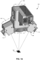
- FIG. 1A illustrates the perspective view of an exemplary 3D smart vision module, according to one embodiment.
- Smart vision module 100 includes a structured-light projector 102, a stereo camera pair that includes a left-stereo camera 104 and a right-stereo camera 106, and a pair of spotlights 112 and 114.
- FIG. 1A also shows the field-of-view (FOV) 108 of smart vision module 100.
- FOV field-of-view
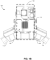
- FIG. 1B illustrates the front view of exemplary 3D smart vision module 100, according to one embodiment.
- FIG. 1B shows more clearly the relative locations among structured-light projector 102, left-stereo camera 104 and right-stereo camera 106, and spotlights 112 and 114.
- FIG. 1B also shows an image-acquisition-and-processing board 110 positioned between left-stereo camera 104 and right-stereo camera 106.
- Structured-light projector 102 is responsible for projecting structured light onto a scene whose images are to be captured. Structured-light illumination has been widely used to obtain 3D information about objects.
- Structured light refers to active illumination of a scene with specially designed, spatially varying intensity patterns.
- An image sensor e.g., a camera
- the principle of structured-light 3D surface imaging techniques is to extract the 3D surface shape based on the information from the distortion of the projected structured-light pattern. Accurate 3D surface profiles of objects in the scene can be computed by using various structured-light principles and algorithms.
- structured-light projector 102 can include a Digital Light Processing (DLP) projector, which can provide a high frame rate and a high resolution.
- the DLP projector can include a digital micromirror device (DMD) to codify the projecting patterns.
- DMD digital micromirror device
- a typical DLP projector can include a light source, a DMD for providing the pattern, and an optical lens/mirror system for expanding and guiding the light beam.
- a light-emitting diode typically provides a light intensity less than one milliwatt per square centimeter (e.g., 0.2 mw/cm 2 ).
- a low light intensity often leads to prolonged exposure time, and hence, a slower camera frame rate.
- a laser can be used as the light source of the structured-light projector. Compared with the LEDs, a laser can provide a much higher brightness and directionality, and can minimize the optical loss as the laser beam passes through the optical system of the projector. As a result, high intensity patterns can be projected on the object, and exposure time can be significantly reduced.
- the higher intensity provided by a laser source can also ensure that the structured-light pattern can have a high contrast (e.g., between black and white stripes). Such sharper images with a better signal-to-noise ratio can correlate to a shorter exposure time, leading to a faster image-capturing speed.
- the laser source used in the structured-light illumination system can emit light of multiple wavelengths. For example, the laser source can sequentially change the wavelength of the emitted light. As the different material surface reflects light differently at a particular wavelength, the sequential change of the laser wavelength enables the smart vision module to delineate the object from background scene.
- the structured-light projector includes an optical modulator that can break up the coherency of the laser light, thus reducing speckles.
- the optical modulator is designed to randomly distort or modulate the wavefront of the laser beam to form a high brightness directional beam with a short coherent length.
- an optical diffuser was employed in the optical modulator, and random surface roughness on the diffuser was introduced to break the spatial coherence.
- the surface roughness can be in the order of the wavelength of the incoming laser beam.
- the optical diffuser comprises a rotating diffuser disc, which can rotate with an angular velocity up to 20,000 RPM.
- the optical diffuser comprises two overlapping discs rotating in opposite directions, with the gap between the two rotating discs minimized to avoid divergence of the laser beam.
- the rotation speed of the two discs can be independently controlled.
- the optical diffuser can include randomized nanostructures deposited onto a glass surface to destroy the spatial coherence.
- Titanium oxide particles with sizes ranging from 100 nm to 10 ⁇ m can be deposited on a glass surface to form an optical diffuser.
- optical properties of the rotating disc can vary in the radial direction and the tangential direction.
- a disc can be divided into multiple sectors. Each sector has a different optical property. When the disc rotates at a high speed, the laser spot scans through those different sectors having different optical properties, which is equivalent to the laser beam passing through all those different diffusers.
- each sector is proportional to the arc length of each sector, and the total effect equals to the sum of the product of transmission and the arc length of all sectors.
- the wavefront becomes more random, and the coherent length of the laser beam decreases.
- the coherent length of the laser beam is reduced to smaller than the surface roughness of the illuminated object, and the speckles can be eliminated.
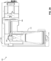
- FIG. 2A illustrates the side view of an exemplary structured-light projector, according to one embodiment.
- Structured-light projector 200 can include a main frame 202 that encloses the various optical components, a laser module 204, an optical diffuser 206, a DMD 208, a beam expanding-and-guiding module 210, and a projector lens 212.
- FIG. 2B illustrates a simplified diagram showing the various optical components within a structured-light projector, according to one embodiment.
- Structured-light projector 220 can include a laser-and-collimator module 222, an optical diffuser disc 224, a DMD 226, a prism 228, and a beam expander 230.
- Laser-and-collimator module 222 can include a laser and collimator, which converts light emitted by the laser to parallel beam.
- the laser can be a multimode laser. In some embodiments, the laser can have tunable wavelengths. In alternative embodiments, laser-and-collimator module 222 can include multiple lasers to generate multiple-wavelength light. To reduce size and power consumption, laser-and-collimator module 222 can include one or more diode lasers (e.g., a GaN laser).
- the collimator can be a condenser lens.
- Diffuser disc 224 can include a holographic diffuser, where the surface texture is precisely controlled to achieve the maximum randomness while maintaining a pre-defined divergence angle.
- the divergence angle at the exit side of the diffuser can range between 0.5° and 10°.
- diffuser disc 224 can spin at a very high RPM (e.g., from a few hundred to a few thousand RPM). This introduces a time-dependent wavefront distortion or randomization, with the captured image being the superposition of many random distorted wavefronts, and as a result, the speckles in the image can be averaged out effectively.
- the randomly etched textures on diffuser disc 224 can be designed to ensure a narrow divergence angle of the laser beam.
- FIG. 2B also shows that, upon exiting diffuser disc 224, the laser beam immediately enters a glass rod 234 functioning as a light tunnel, which can also be considered as part of the optical modulator for wavefront distortion. More specifically, the wavefronts of the laser beam are further randomized via many total internal reflections in the light tunnel.
- the aspect ratio of the light tunnel can be at least 14.
- the light tunnel can also be curve-shaped (e.g., S-shaped). The minimum radius of the curvature can be controlled to maintain total internal reflection.
- the light tunnel can also be a bundle of optical fibers.
- the rotation of diffuser disc 224 can be driven by a multi-pole brushless direct current (BLDC) motor 232.
- BLDC brushless direct current
- the BLDC motor can be highly efficient, compact in size, low noise, and can have a higher speed range.
- multi-pole BLDC motor 232 can be mounted on fluid dynamic bearings (FDBs).
- FDBs fluid dynamic bearings
- BLDC motor 232 can be designed to be small and flat, as shown in FIG. 2B .
- diffuser disc 224 very close (e.g., less than one centimeter) to laser-and-collimator module 222, thus minimizing the divergence angle of the laser beam and minimizing the loss.
- This design also allows diffuser disc 224 to spin with low noise and minimized wobbling, and increased life span of the bearings.
- the diffuser module includes multiple (e.g., two) spinning diffuser discs, with each diffuser disc being similar to diffuser disc 224 shown in FIG. 2B .
- FIG. 3A shows the amplified view of two diffusers in the path of the laser beam, according to one embodiment.
- a diffuser disc 302 is coupled to and driven by a rotational motor 304 and a diffuser disc 306 is coupled to and driven by a rotational motor 308.
- Diffuser discs 302 and 306 partially overlap with each other, and the collimated laser beam out of collimator 310 passes through the overlapping portions of diffuser discs 302 and 306 before reaching other optical components.
- FIG. 3B shows the top view of the overlapping diffuser discs, according to one embodiment. More specifically, FIG. 3B clearly shows that the edges of diffuser discs 302 and 306 partially overlap each other. The laser beam hits and passes through the overlapping regions of diffuser discs 302 and 306 before continuing on each path.
- the high-speed rotations of the diffuser discs can result in a number of un-correlated (due to the randomness of scattering patterns) speckles being averaged within a captured frame, thus mitigating the speckle effect.
- the two diffuser discs rotate in different directions at different speeds. For example, diffuser disc 302 can rotate clockwise at a speed of 500 RPM, whereas diffuser disc 306 can rotate counterclockwise at a speed of 600 RPM. Other combinations can also be possible. For example, diffuser disc 302 can rotate counterclockwise at a speed of 5000 RPM, whereas diffuser disc 306 can rotate clockwise at a speed of 4000 RPM.
- Both discs can rotate at speeds up to 20,000 RPM.
- one diffuser disc can remain stationary while the other rotates.
- the rotation speeds of the discs can also be time-varying.
- multiple (e.g., more than two) discs can be deployed, with the multiple discs rotating at different speeds in different directions. The rotation speeds of the multiple discs can also be independently controlled.
- FIG. 3C shows the top view of an exemplary diffuser disc, according to one embodiment.
- diffuser disc 320 is divided into 24 sectors along with the radial direction and the tangential direction. Each sector has a different optical property (e.g., a different surface roughness parameter Ra, or a different refractive index).
- the optical property can be any property that distorts the wavefront of a coherent beam.
- laser beam spot 322 scans through those different sectors having different optical properties. The total scattering effect reduces the coherent length of the laser beam.
- the laser beam passes through diffuser disc 224, it arrives at prism 228, which change the direction of the parallel laser beam, causing a portion of the laser beam to be reflected off DMD 226.
- DMD 226 is a bi-stable spatial light modulator.
- DMD 226 can include a two-dimensional (2D) array (e.g., a 1280 ⁇ 720 array) of movable micromirrors functionally mounted over a CMOS memory cell.
- Each mirror can be independently controlled by loading data into the CMOS memory cell to steer reflected light, spatially mapping a pixel of video data to a pixel on a display. Therefore, by switching the tilting directions of each individual micromirror, a pattern of bright (or white) and dark (or black) pixels can be created.
- the intensity of the illumination pattern can be a sinusoidal function.
- other encoded patterns such as dot array or grid, can also be used as the structured light for illumination.
- Beam expander 230 is used to expand the size of the parallel beam. Expanding the beam can decrease the divergence angle, thus increasing the depth of field (DOF) of the DLP projector.
- Various types of beam expander can be used to increase the size of the parallel beam, including but not limited to: a Keplarian beam expander, a Galilean beam expander, and, according to the invention defined in claim 10, a double-telecentric lens system.
- beam expander 230 includes a double-telecentric lens system, which can expand the beam with little to no distortion and divergence.
- Double-telecentric lens system 230 can provide constant magnification on the projection screen at various depths within the focused zone. Note that, even though the camera and projection optical units are calibrated, the non-telecentric approach can result in various resolutions of a measured image at various DOFs due to different lens magnifications. A telecentric lens system can improve this phenomenon as well as provide a very low or near zero distortion of projected patterns as depth varies. It also improves the depth of the projected field due to zero angle of projection.
- left-stereo camera 104 and a right-stereo camera 106 are located on either side of the optical axis of structured-light projector 102. In one embodiment, these cameras can be used for generating 3D point cloud models as well as performing two-dimensional (2D) wide-field part scan and object detecting. Left and right cameras 104 and 106 are mounted with a defined tilted angle with respect to the projection beam emitted by structured-light projector 102.
- dual cameras e.g., left and right cameras 104 and 106
- dual cameras can provide the benefit of reducing the amount of specular reflection, which is a type of surface reflectance described as a mirror-like reflection. Such reflections can cause overexposure (e.g., the specular highlight) and are often undesirable.
- specular reflection can be reduced.
- specular reflection is highly directional, specular light reflecting into one camera is less likely to reach the other camera.
- information associated with a region that causes specular reflection in one camera can be captured by the other camera.
- the output image of one camera where the read out is saturated due to specular reflection can be compensated for by the output image of the other camera.
- a similar principle can be used to minimize occlusion.
- a 3D smart vision module can include multiple dual-camera pairs, which can create 3D visions at different accuracies and fields of view (FOVs).
- 3D smart vision module 100 includes two dual-camera pairs, one pair including cameras 104 and 106 (referred to as the inner pair, and additional camera pairs can be added.
- a camera pair on the outside of cameras 106 and 106 can be referred to as an outer pair.
- the outer camera pair captures images under the illumination by structured light projected by structured-light projector 102, and can form 3D visions with accuracy down to a few microns.
- the inner camera pair captures images under normal illumination (i.e., no structured light), and can form a 3D vision in a large area at very high speed with reasonable accuracy.
- the inner camera pair can have a larger FOV than that of the outer camera pair.
- each dimension of the FOV of the inner camera pair can be a few hundred of millimeters (e.g., 150 ⁇ 100 mm 2 ), whereas the dimension of the FOV of the outer camera pair can be a few tens of millimeters (e.g., 50 ⁇ 40 mm 2 ).
- the different FOVs and resolutions provided by the two camera pairs provide operational flexibility.
- the inner camera pair can be used to scan a larger area to identify a component, whereas the outer camera pair can be used to zoom in to capture more detailed images of a single component.
- FIG. 4 illustrates exemplary arrangements of dual-camera pairs, according to one embodiment. More specifically, FIG. 4 shows the top view of a smart vision module 400 with two different ways to arrange its cameras. Smart vision module 400 can include a dual-camera pair 402 arranged in a way similar to what is shown in FIGs. 1A and 1B . Alternatively, smart vision module 400 can include a dual-camera pair 404 arranged by rotating dual-camera pair 402 90° around projector 406. Other angles (e.g., 30°, 45°, 60°, etc.) are also possible.
- smart vision module 400 can include both dual-camera pairs 402 and 404, with both camera pairs operating in a synchronized way with projector 406 (meaning that for each structured-light pattern projected by projector 406, both camera pairs capture one or more images). In this way, a complete point cloud without occlusion can be formed.
- a machine-vision system can include multiple (e.g., two or four) smart vision modules that can be configured to capture images in an alternating manner. More particularly, the multiple smart vision modules can have different viewing angles, with respect to the object, thus allowing the measurement of the object's 3D information from multiple angles and minimizing optical occlusion. Certain object features that are out of view of one smart vision module can be seen by the other.
- FIG. 5 illustrates an exemplary machine-vision system, according to one embodiment.
- Machine-vision system 500 can include a supporting frame 502 for supporting the multiple smart vision modules.
- supporting frame 502 can include an arc-shaped slot 504 on which the multiple smart vision modules (e.g., modules 506 and 508) are mounted.
- the arc shape of slot 504 i.e., being a portion of a circle
- smart vision modules 506 and 508 can share a same FOV 510, which is located near the center of the circle.
- arc-shaped slot 504 also allows a smart vision module to change its viewing angle by sliding along slot 504 while its viewing distance remains the same.
- each smart vision module can be a dual-camera module comprising two cameras, similar to camera 104 and 106 shown in FIGs. 1A and 1B .
- the two cameras for each smart vision module can be aligned such that the camera plane (i.e., the plane defined by the optical axes of the two cameras) and the projection plane (i.e., the plane defined by the optical axis of the projector as the projector moves along slot 504) are perpendicular to each other.
- FIG. 5 shows the front view of machine-vision system 500, with the projection plane being the plane of the paper and a line connecting the two cameras going in and out of the plane of the paper.
- optical axes of all four cameras of smart vision modules 506 and 508 converge at a single point (i.e., a point substantially at the center of the circle). Similarly, the optical axes of the two projectors of the two smart vision modules can also converge at the same point.
- the ability to include multiple smart vision modules having different viewing angles and the ability to adjust the viewing angle of the vision modules without changing the FOV can provide the machine-vision system a greater flexibility in capturing images of different types of object.
- Some types of object may be viewed top down, whereas some types of object may be viewed at the wide viewing angle.
- the tilt angle of the smart module can be adjusted in order to allow the cameras to capture images of the recessed region with minimal occlusion.
- the multiple (e.g., two) smart vision modules can operate independently.
- the smart vision modules can be turned on in an alternating fashion, where each camera pair captures images under illumination by the structured-light from the corresponding projector. 3D images from the two vision modules can be combined to generate final images of the observed object.
- the multiple (e.g., two) smart vision modules can operate in tandem, with one vision module being the master and other vision modules being the slaves.
- smart vision module 506 can operate as a master, whereas smart vision module 508 can operate as the slave.
- the structured-light projector of smart vision module 506 is tuned on to project structured patterns on to the object and the structured light projector of vision module 508 is turned off. All four cameras (i.e., the four cameras of both vision modules) are synchronized to the projector of master vision module 506 to capture a sequence of images under illumination by certain structured-light patterns.
- the master-slave combination up to eight point clouds from four cameras viewing from four different angles can be obtained. Through superposition of these point clouds, occlusion and specular reflection can be minimized.
- Each smart vision module can be equipped with a processor configured to control operations of the projector and cameras as well as process the images captured by the dual cameras. More specifically, the processor can extract 3D information (e.g., generating a 3D point cloud of the object) from the captured images based on the projected structured-light patterns.
- the processors of the vision modules can operate in tandem, with one processor operating in the master mode and the other processor operating in the slave mode. More particularly, the master processor controls the operations of the various controllers of the laser, the DMD, and the cameras within the master vision module.
- the master processor can send synchronized control signals to the slave processor, thus facilitating the slave processor in controlling the operations of the cameras of the slave vision module so that they are in sync with those of the master vision module.
- the camera controller i.e., the control unit that controls the timing of camera acquisition
- the camera controller can receive timing inputs from the processors, thus providing the flexibility of synchronizing latency of capture-trigger timing of individual dual-camera pairs with multiple structured-light projection modules. This allows image acquisition under the illumination by structured-light patterns from multiple views at the same time, thus making it possible to reconstruct a complete 3D representation of an object with minimized occlusion.
- the support frame can have multiple intercepting arches, with each arch having multiple vision modules mounted on the arch.
- the support frame can include a dome structure, with each vision module being mounted at a particular location on top of the dome.
- FIG. 6 illustrates the top view of an exemplary machine-vision system that includes a cluster of smart vision modules, according to one embodiment.
- machine-vision system 600 can include four smart vision modules, modules 602, 604, 606, and 608. Each vision module can be similar to the one shown in FIGs. 1A and 1B . Similar to the machine-vision system shown in FIG. 5 , the different vision modules in machine-vision system 600 can operate independently of each other or in tandem. The additional vision modules can provide additional viewing options, making it easier to reconstruct a complete 3D representation (e.g., a 3D point cloud) of the object. Moreover, the ability to position vision modules in any desired location to have any viewing angle can also provide six degrees of freedom (6DOF).
- 6DOF degrees of freedom
- each smart vision module can include a processor, which can be enclosed within the same physical enclosure of the cameras, as shown in FIG. 1B .
- a processor which can be enclosed within the same physical enclosure of the cameras, as shown in FIG. 1B .
- Such an on-board processor enables edge computing with board-level integration of all data-acquisition modules of the cameras.
- image-acquisition-and-processing board 110 can integrate the processor and the image-acquisition onto a single printed circuit board (PCB), and it can be included in the same physical enclosure that houses the projector and the cameras.
- PCB printed circuit board
- Such an integrated board can provide high data throughput in terms of image capturing and processing. Integrating the real time 3D image acquisition and processing modules into the same unit can significantly reduce latency, and can also make the unit portable and provide flexibility to integrate with many robotic systems and/or other transport vehicles. Note that the reduced latency is an important factor in ensuring real-time 3D object tracking.
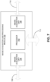
- FIG. 7 illustrates an exemplary image-acquisition-and-processing module, according to one embodiment.
- Image-acquisition-and-processing module 700 can include an on-board processor 702 and two separate image-acquisition units 704 and 706. Each of the image-acquisition units can include an application-specific integrated circuit (ASIC) chip.
- ASIC application-specific integrated circuit
- Processor 702 and image-acquisition units 704 and 706 can be mounted onto a single board, which can be custom designed or a standard CPU board.
- image-acquisition-and-processing module 700 can also include a memory (not shown in FIG. 7 ) that can be shared between image-acquisition units 704 and 706.
- the memory can store instructions that can be loaded into processor 702 to facilitate processor 702 in performing computation (e.g., image processing). It is also possible to temporarily store images captured by the cameras in the memory.
- Image-acquisition-and-processing module 700 can also include a number of high-speed interfaces, such as image-sensor interfaces 708 and 710 and processor interface 712.
- Image-sensor interfaces 708 and 710 enable, respectively, image-acquisition units 704 and 706 to interface with the two cameras. More specifically, images captured by the cameras are transmitted to image-acquisition units 704 and 706 via image-sensor interfaces 708 and 710, respectively. Eventually the image data is transferred, at a high speed, to processor 702 for processing.
- control signals that control the operations of the cameras e.g., the capturing of images, the shutter speed, the focus, etc.
- processor interface 712 allows processor 702 to interface with a host computer.
- the image-processing result generated by processor 702 can be sent to the host computer.
- the host computer can combine image-processor results from multiple different processors (e.g., the different processors belonging to different vision modules) in order to construct a complete 3D image (e.g., a 3D point cloud) of the object that is under observation.
- the various interfaces can be high-speed data interfaces, such as peripheral component interconnect express (PCIe) interfaces.
- PCIe peripheral component interconnect express
- image-sensor interfaces 708 and 710 can each run at a speed of about 2.8 Gbps
- processor interface 712 can run at a speed of about 5.6 Gbps.
- Such high data-communication speeds are important in ensuring the operation speed of the entire machine-vision system.
- FIG. 8 shows a block diagram of an exemplary 3D machine-vision system, according to one embodiment.
- 3D machine-vision system 800 can include a host computer 802, a support structure 804, and multiple smart vision modules (e.g., vision modules 810 and 820) in communication with host computer 802 and mounted on support structure 804.
- multiple smart vision modules e.g., vision modules 810 and 820
- the multiple vision modules can each be a stand-alone module, and can be configured to operate independently of each other or in tandem.
- Smart vision module 810 can include a camera pair 812, a structured-light projector 814, a main-controller module 816, and a secondary-controller module 818.
- smart vision module 820 can include a camera pair 822, a structured-light projector 824, a main-controller module 826, and a secondary-controller module 828.
- Each camera pair can include two cameras with high data speed (e.g., greater than 2.8 Gbps), high-resolution (e.g., greater than 2.8 M pixels), and high frame rate (e.g., 400 frames per second or higher).
- the camera pair can provide stereo vision even when the structured-light projector is not on. This can allow for faster object identification and tracking, whereas structured-light based image capturing can provide 3D images at a higher resolution.
- each smart vision module it is also possible for each smart vision module to include multiple camera pairs capable of providing images at different resolutions.
- Each structured-light projector can include a laser-and-collimator module, an optical modulator (which can include a diffuser and a light tunnel), a DMD, a prism, and a beam expander.
- the optical modulator 2. includes two partially overlapping diffuser discs rotating at different speeds in opposite directions. Each diffuser disc can be driven by a BLDC motor mounted using FDBs, thus enabling the diffuser disc to spin with low-noise and minimum wobbling.
- the random patterns etched on the diffuser discs can be designed to ensure a narrow divergence angle (e.g., between 0.5° and 10°). Including the optical diffuser discs in the path of the laser beam can eliminate laser speckles and improve the uniformity of the structured-light patterns.
- Each main-controller module can be similar to image-acquisition-and-processing module 700 shown in FIG. 7 . More specifically, each main-controller module can include a processor, a memory, and multiple image-acquisition units, with each image-acquisition unit interfacing with a camera.
- the processor can be used to process data provided by image sensors of the cameras using various digital image processing technologies, such as filtering, applying various structured-light algorithms, etc.
- the processor can also combine data from the different cameras to eliminate specular reflections captured by each single camera.
- the processor can also use the image data to generate a 3D point cloud for the object being observed. Depending on the resolution of the image data, a low- or high-resolution 3D point cloud can be generated.
- the main-controller module of each vision module can be enclosed in a same physical enclosure that houses the cameras and projector of the vision module, thus providing portability of the vision module while reducing data latency.
- Each secondary-controller module can include controllers for other components in the corresponding smart vision system, such as a laser controller for controlling the laser (e.g., emitting wavelength and intensity) within the structured-light projector, a DMD controller for controlling the DMD (e.g., the pattern and frame rate), and a diffuser controller for controlling the spin (e.g., direction and speed) of the diffuser discs. More specifically, the laser controller can control the emitting wavelength and intensity of the laser based on the surface condition of the object under observation.
- the DMD can be configured such that the projector can project different patterns (e.g., dot arrays, parallel lines, grids, etc.) on to the object.
- the DMD frame rate can be 10-20 frames per second, or higher.
- Diffuser controllers can be configured in such a way that two diffuser discs in the diffuser module spin at high RPM (e.g., hundreds or thousands of RPM) in opposite directions.
- the various controllers within the secondary controller module can also be integrated onto a PCB.
- FIG. 9 illustrates an exemplary computer and communication system that facilitates the 3D machine-vision system, according to one embodiment.
- a computer and communication system 902 includes a processor 904, a memory 906, and a storage device 908.
- Storage device 908 stores various applications that can be used to facilitate operations of the 3D machine-vision system, such as a machine-vision application 910, as well as other applications, such as applications 912 and 914.
- machine-vision application 910 can be loaded from storage device 908 into memory 906 and then executed by processor 904. While executing the program, processor 904 performs the aforementioned functions.
- Computer and communication system 902 is coupled to an optional display 916, keyboard 918, and pointing device 920.
- inventions of the present application can provide a 3D machine-vision system that can be used to facilitate operations of a robotic system.
- the 3D machine-vision system can include a DMD-based structured-light projection system that uses a high power, multimode, multi-wavelength laser module as a light source.
- the structured-light projection system can also include an optical diffuser with a narrow divergence angle to reduce or eliminate speckles.
- the optical diffuser can include two low-noise, high-RPM, vibration-free rotating discs driven by BLDC motors mounted using FDBs. The compact size and stability of the BLDC motors make it possible for the diffuser discs to be positioned very close to the laser source, thus further reducing beam divergence.
- the structured-light projection system uses a high resolution double-telecentric lens system to expand the laser beam and a DMD to generate high-resolution structured-light patterns.
- Such structured-light patterns can include digitized patterns (e.g., binary patterns) or analog patterns where light intensity changes gradually.
- the disclosed embodiments provide board-level integration of multiple cameras having high data speed (e.g., greater than 2.8 Gbps), high frame rate (e.g., greater than 400 frames-per-second), and high resolution (e.g., greater than 2.8 M pixels) to enable high resolution 3D point cloud generation in real time, for six degrees of freedom (6DOF) 3D object identification, 3D tracking, and localization.
- 6DOF degrees of freedom
- the methods and processes described in the detailed description section can be embodied as code and/or data, which can be stored in a computer-readable storage medium as described above.
- a computer system reads and executes the code and/or data stored on the computer-readable storage medium, the computer system performs the methods and processes embodied as data structures and code and stored within the computer-readable storage medium.
- the methods and processes described above can be included in hardware modules or apparatus.
- the hardware modules or apparatus can include, but are not limited to, application-specific integrated circuit (ASIC) chips, field-programmable gate arrays (FPGAs), dedicated or shared processors that execute a particular software module or a piece of code at a particular time, and other programmable-logic devices now known or later developed.
- ASIC application-specific integrated circuit
- FPGA field-programmable gate arrays
- dedicated or shared processors that execute a particular software module or a piece of code at a particular time
- other programmable-logic devices now known or later developed.
Landscapes
- Physics & Mathematics (AREA)
- Engineering & Computer Science (AREA)
- General Physics & Mathematics (AREA)
- Multimedia (AREA)
- Signal Processing (AREA)
- Optics & Photonics (AREA)
- Computer Vision & Pattern Recognition (AREA)
- Theoretical Computer Science (AREA)
- Length Measuring Devices By Optical Means (AREA)
Description
- This disclosure is generally related to machine-vision systems. More specifically, this disclosure is related to a machine-vision system capable of performing three-dimensional (3D) pose measurement with high precision and real-time object tracking.
- Computer vision is a field of artificial intelligence (AI) that trains computers to interpret and understand the visual world. Using digital images from cameras and videos and applying deep-learning models, machines can accurately identify and position objects. Industrial automation and robot-assisted manufacturing are increasingly using such technologies to improve their factory throughput and flexibility to respond efficiently to customers' needs and desires, as well as to maximize yield. A high-definition camera can detect details that human eyes cannot, and a fast computer processor can interpret the images and perform various complicated tasks of inspection and assembly (e.g., object recognition, micron-level crack detection, surface-defect detection, etc.) as fast as a human brain, but with a much higher repeatability and accuracy.
- With the rapid advancement of AI and machine-learning algorithms, the industry is pushing in two key directions: one toward training or teaching the robots, and the other toward developing a faster way to generate 3D models of the objects without sacrificing measurement resolution. The second approach is especially required when robots are dealing with 3D irregular and flexible objects, where accurate acquisition of 6-degree of freedom (6DOF) and rapid response to objects' motion are of vital importance.
- Schaffer Martin, et al., "Statistical patterns: an approach for high-speed and high-accuracy shape measurements", Optical Engineering, Soc. of Photo-Optical Instrumentation Engineers, Bellingham, vol. 53, no. 11, 1 November 2024; https://www.spiedigitallibrarv.org/journals/optical-engineering/volume-53/issue-11/112205/Statistical-patterns--an-approach-for-high-speed-and-high/10.1117/1.OE.53.11.112205.short, in an abstract states that "Statistical patterns have been used for structured illumination within a stereo-photogrammetry setup to precisely measure the shape of nearly arbitrary objects in a short time. This contribution gives an overview of recently developed projection setups based on such statistical patterns. Coherent and incoherent approaches as well as the applied reconstruction algorithm are explained. The results show the suitability of the statistical pattern projection approach to replace the commonly used slow digital light processing (DLP) projectors of three-dimensional shape sensors and facilitate measurements in an ultrashort time frame (microsecond range), e.g., to track moving objects."
-
US2019/045173A1 in an abstract states that "Systems, devices, and techniques related to matching features between a dynamic vision sensor and one or both of a dynamic projector or another dynamic vision sensor are discussed. Such techniques include casting a light pattern with projected features having differing temporal characteristics onto a scene and determining the correspondence(s) based on matching changes in detected luminance and temporal characteristics of the projected features." -
US2011/037953A1 in an abstract states that "The present invention provides a projection display comprising an illumination system comprising at least one laser source unit and configured and operable for producing one or more light beams; a spatial light modulating (SLM) system accommodated at output of the illumination system and comprising one or more SLM units for modulating light incident thereon in accordance with image data; and a light projection optics for imaging modulated light onto a projection surface. The illumination system comprises at least one beam shaping unit comprising a Dual Micro-lens Array (DMLA) arrangement formed by front and rear micro-lens arrays (MLA) located in front and rear parallel planes spaced-apart along an optical path of light propagating towards the SLM unit, the DMLA arrangement being configured such that each lenslet of the DMLA directs light incident thereon onto the entire active surface of the SLM unit, each lenslet having a geometrical aspect ratio corresponding to an aspect ratio of said active surface of the SLM unit." -
CN107643645A in an abstract states that "The invention relates to the laser display technology field and particularly discloses an RGB three color laser light source projection system in order to solve problems of a speckle effect and non-uniformity in laser projection display and a problem that three-color laser coupling is too complicated. The RGB three-color laser light source projection system comprises an RGB array laser light source module, an X type coupler, a beam shrinkage lens set, a homogenization and speckle elimination device, a shaping lens set, a TIR prism, a DLP modulator and a projection lens. The volume of the RGB three-color laser light source module is reduced through optimizing structures of the RGB array laser light source module and an X type coupler, and the cost is reduced. The homogenization and speckle elimination device is utilized to successfully solve problems of uniformity and speckles of the RGB three-color laser display. The RGB three color laser light source projection system is applicable toa projection system like a projector." -
CN108398804A in an abstract states that "The invention discloses a laser speckle optical path and a laser projection light source system, and relates to the technical field of laser display. The system comprises a diffusion assembly and a lens assembly used for collimation and spotlight, the diffusion assembly is composed of at least two diffusion parts, wherein one of the diffusion parts is a dynamic speckle device, the other diffusion parts are static speckle devices, and the movement mode of the dynamic speckle device is cyclical rotation; and the lens assembly is arranged among the diffusion parts. The laser speckle optical path and the laser projection light source system have the advantages that better speckle and facula homogenization functions can be achieved through the combined use of the dynamic diffusion assembly and static diffusion assemblies; the laser beams are diverged and collimated repeatedly to greatly reduce the spatial coherence of the laser beams, thereby effectively solving the problem of speckle; the laser speckle optical path is simple in structure and small is size, and can be integrated easily in a laser display system to make the structure of an x ray machine more compact." - The present invention is set out in the independent claims, with some optional features set out in the claims dependent thereto.
- One embodiment provides a machine-vision system that includes one or more stereo-vision modules. A respective stereo-vision module can include a structured-light projector, a first camera positioned on a first side of the structured-light projector, and a second camera positioned on a second side of the structured-light projector. The first and second cameras are configured to capture images of an object under illumination by the structured-light projector. The structured-light projector can include a laser-based light source and an optical modulator configured to reduce speckles caused by the laser-based light source.
- In a further variation, the optical modulator can further include a straight or curved light tunnel.
- According to the invention, the optical diffuser includes two diffuser discs rotating at different speeds in opposite directions.
- In a further variation, rotation speeds of the two diffuser discs can be controlled independently of each other.
- In a further variation, the rotating diffuser disc is driven by a brushless direct current (BLDC) motor.
- In a variation on this embodiment, the laser-based light source can be configured to emit a multimode, multi-wavelength laser beam.
- In a variation on this embodiment, the machine vision system can further include a support frame to mount the one or more stereo-vision modules. The support frame can include at least an arc-shaped slot such that first and second stereo-vision modules mounted on the arc-shaped slot have a same viewing distance but different viewing angles when capturing images of the object.
- In a further variation, optical axes of the first and second cameras of the first and second stereo-vision modules mounted on the arc-shaped slot are configured to converge at a single point.
- In a further variation, the first and second stereo-vision modules operate in tandem, with the first stereo-vision module operating as a master and the second stereo-vision module operating as a slave.
- In a further variation, while operating as a slave, the second stereo-vision module is configured to: turn off a structured-light projector of the second stereo-vision module, and synchronize first and second cameras of the second stereo-vision module with a structured-light projector of the first stereo-vision module.
- In a variation on this embodiment, the structured-light projector can include: a digital micromirror device (DMD) for reflecting a laser beam outputted by the laser-based light source and modulated by the optical modulator, and a double-telecentric lens for expanding the laser beam reflected by the DMD while maintaining parallelism of the beam.
- In a variation on this embodiment, the respective stereo-vision module further includes an image-acquisition-and-processing module, which includes a processor and multiple image-acquisition units integrated onto a same printed circuit board (PCB).
- In a further variation, the image-acquisition-and-processing module can include:
an image-sensor interface configured to facilitate high-speed data transfer to the processor, and a processor interface configured to facilitate high-speed communication between the processor and a host computer. - In a further variation, the image-sensor interface and the processor interface are peripheral component interconnect express (PCIe) interfaces.
- One embodiment provides a structured-light projector for a 3D imaging system. The structured-light projector includes a laser-based light source, an optical modulator configured to reduce speckles caused by the laser-based light source, the optical modulator comprising two diffuser discs rotating at different speeds in opposite directions, a digital micromirror device
(DMD) for reflecting a laser beam outputted by the laser-based light source and modulated by the optical modulator, and a double-telecentric lens for expanding the laser beam reflected by the DMD while maintaining parallelism of the laser beam. -
-
FIG. 1A illustrates the perspective view of an exemplary 3D smart vision module, according to one embodiment. -
FIG. 1B illustrates the front view of exemplary 3Dsmart vision module 100, according to one embodiment. -
FIG. 2A illustrates the side view of an exemplary structured-light projector, according to one embodiment. -
FIG. 2B illustrates a simplified diagram showing the various optical components within a structured-light projector, according to an embodiment not encompassed by the wording of the claims but considered as useful for understanding the invention. -
FIG. 3A shows the amplified view of two diffusers in the path of the laser beam, according to one embodiment. -
FIG. 3B shows the top view of the overlapping diffuser discs, according to one embodiment. -
FIG. 3C shows the top view of an exemplary diffuser disc, according to one embodiment. -
FIG. 4 illustrates exemplary arrangements of dual-camera pairs, according to one embodiment. -
FIG. 5 illustrates an exemplary machine-vision system, according to one embodiment. -
FIG. 6 illustrates the top view of an exemplary machine-vision system that includes a cluster of smart vision modules, according to one embodiment. -
FIG. 7 illustrates an exemplary image-acquisition-and-processing module, according to one embodiment. -
FIG. 8 shows a block diagram of an exemplary 3D machine-vision system, according to one embodiment. -
FIG. 9 illustrates an exemplary computer and communication system that facilitates the 3D machine-vision system, according to one embodiment. - In the figures, like reference numerals refer to the same figure elements.
- The following description is presented to enable any person skilled in the art to make and use the embodiments, and is provided in the context of a particular application and its requirements. Various modifications to the disclosed embodiments will be readily apparent to those skilled in the art, and the general principles defined herein may be applied to other embodiments and applications without departing from the scope of the present disclosure. Thus, the present invention is not limited to the embodiments shown, but is to be accorded the widest scope consistent with the principles and features disclosed herein.
- Embodiments described herein solve the technical problem of providing
high accuracy 3D pose measurement and tracking of an object in a real-time 3D workspace. More specifically, the disclosed embodiments provide a smart vision system that uses high-frame rate image sensors with laser structural light patterns to generate a high-resolution point cloud representing a tracked object. The smart vision system includes an optical-projection unit with a single- or multiple-wavelength laser source to address absorbance or reflection spectrum of various surface materials and to achieve optimum image quality. The smart vision system also includes an optical modulator in line with the laser beam to minimize or eliminate speckle effects from the laser source. The smart vision system further includes a double-telecentric projection lens system to allow a constant magnification as depth varies and to achieve a very low to near zero distortion of projected patterns on the object, and to improve the depth of focus (DOF) of the projected patterns. To minimize specular reflection and object occlusion, the smart vision system can include multiple image sensors located in multiple locations with their optical axes converging to a common point intersecting with the optical axis of the optical-projection unit. -
FIG. 1A illustrates the perspective view of an exemplary 3D smart vision module, according to one embodiment.Smart vision module 100 includes a structured-light projector 102, a stereo camera pair that includes a left-stereo camera 104 and a right-stereo camera 106, and a pair ofspotlights FIG. 1A also shows the field-of-view (FOV) 108 ofsmart vision module 100. -
FIG. 1B illustrates the front view of exemplary 3Dsmart vision module 100, according to one embodiment.FIG. 1B shows more clearly the relative locations among structured-light projector 102, left-stereo camera 104 and right-stereo camera 106, and spotlights 112 and 114.FIG. 1B also shows an image-acquisition-and-processing board 110 positioned between left-stereo camera 104 and right-stereo camera 106. - Structured-
light projector 102 is responsible for projecting structured light onto a scene whose images are to be captured. Structured-light illumination has been widely used to obtain 3D information about objects. The term "structured light" refers to active illumination of a scene with specially designed, spatially varying intensity patterns. An image sensor (e.g., a camera) acquires 2D images of the scene under the structured-light illumination. If the scene is a planar surface without any 3D surface variation, the pattern shown in the acquired image is similar to that of the projected structured-light pattern. However, when the surface in the scene is non-planar, the geometric shape of the surface distorts the projected structured-light pattern as seen from the camera. The principle of structured-light 3D surface imaging techniques is to extract the 3D surface shape based on the information from the distortion of the projected structured-light pattern. Accurate 3D surface profiles of objects in the scene can be computed by using various structured-light principles and algorithms. - In some embodiments, structured-
light projector 102 can include a Digital Light Processing (DLP) projector, which can provide a high frame rate and a high resolution. The DLP projector can include a digital micromirror device (DMD) to codify the projecting patterns. A typical DLP projector can include a light source, a DMD for providing the pattern, and an optical lens/mirror system for expanding and guiding the light beam. - Conventional structured-light projectors often use a light-emitting diode (LED) as the light source, which typically provides a light intensity less than one milliwatt per square centimeter (e.g., 0.2 mw/cm2). A low light intensity often leads to prolonged exposure time, and hence, a slower camera frame rate. To increase the light intensity, in some embodiments, a laser can be used as the light source of the structured-light projector. Compared with the LEDs, a laser can provide a much higher brightness and directionality, and can minimize the optical loss as the laser beam passes through the optical system of the projector. As a result, high intensity patterns can be projected on the object, and exposure time can be significantly reduced.
- The higher intensity provided by a laser source can also ensure that the structured-light pattern can have a high contrast (e.g., between black and white stripes). Such sharper images with a better signal-to-noise ratio can correlate to a shorter exposure time, leading to a faster image-capturing speed. Moreover, in some embodiments, the laser source used in the structured-light illumination system can emit light of multiple wavelengths. For example, the laser source can sequentially change the wavelength of the emitted light. As the different material surface reflects light differently at a particular wavelength, the sequential change of the laser wavelength enables the smart vision module to delineate the object from background scene.
- When the object is illuminated by the laser, the inherently rough surface of the object can cause the backscattered light to create a speckled pattern, which can include bright and dark regions. The speckle effect can create objectionable noise signals to the images captured by the smart vision system. Multimode lasers have shorter coherent lengths than single mode lasers, and can reduce the speckle effect slightly. To minimize speckles, according to the invention, the structured-light projector includes an optical modulator that can break up the coherency of the laser light, thus reducing speckles. To destroy the spatial coherence, the optical modulator is designed to randomly distort or modulate the wavefront of the laser beam to form a high brightness directional beam with a short coherent length. According to the invention, an optical diffuser was employed in the optical modulator, and random surface roughness on the diffuser was introduced to break the spatial coherence. The surface roughness can be in the order of the wavelength of the incoming laser beam. More specifically, the optical diffuser comprises a rotating diffuser disc, which can rotate with an angular velocity up to 20,000 RPM. To further increase the randomness of the optical diffuser, according to the invention, the optical diffuser comprises two overlapping discs rotating in opposite directions, with the gap between the two rotating discs minimized to avoid divergence of the laser beam. In further embodiments, the rotation speed of the two discs can be independently controlled.
- In addition to surface roughness, the optical diffuser can include randomized nanostructures deposited onto a glass surface to destroy the spatial coherence. For example, Titanium oxide particles with sizes ranging from 100 nm to 10 µm can be deposited on a glass surface to form an optical diffuser. In another embodiment, optical properties of the rotating disc can vary in the radial direction and the tangential direction. For example, a disc can be divided into multiple sectors. Each sector has a different optical property. When the disc rotates at a high speed, the laser spot scans through those different sectors having different optical properties, which is equivalent to the laser beam passing through all those different diffusers. The contribution of each sector is proportional to the arc length of each sector, and the total effect equals to the sum of the product of transmission and the arc length of all sectors. As the disc is divided into more sectors of different roughness, the wavefront becomes more random, and the coherent length of the laser beam decreases. Ultimately the coherent length of the laser beam is reduced to smaller than the surface roughness of the illuminated object, and the speckles can be eliminated.
-
FIG. 2A illustrates the side view of an exemplary structured-light projector, according to one embodiment. Structured-light projector 200 can include amain frame 202 that encloses the various optical components, alaser module 204, anoptical diffuser 206, aDMD 208, a beam expanding-and-guidingmodule 210, and aprojector lens 212. -
FIG. 2B illustrates a simplified diagram showing the various optical components within a structured-light projector, according to one embodiment. Structured-light projector 220 can include a laser-and-collimator module 222, anoptical diffuser disc 224, aDMD 226, aprism 228, and abeam expander 230. - Laser-and-
collimator module 222 can include a laser and collimator, which converts light emitted by the laser to parallel beam. The laser can be a multimode laser. In some embodiments, the laser can have tunable wavelengths. In alternative embodiments, laser-and-collimator module 222 can include multiple lasers to generate multiple-wavelength light. To reduce size and power consumption, laser-and-collimator module 222 can include one or more diode lasers (e.g., a GaN laser). The collimator can be a condenser lens. -
Diffuser disc 224 can include a holographic diffuser, where the surface texture is precisely controlled to achieve the maximum randomness while maintaining a pre-defined divergence angle. In some embodiment, the divergence angle at the exit side of the diffuser can range between 0.5° and 10°. As the laser beam passes this randomly textured surface, the wavefronts are broken up due to scattering, and the coherent length is reduced. Consequently, the speckles are reduced or even eliminated in the captured images. The hatched areas indicate where the laser beam interacts withdiffuser disc 224 at a particular time instant. The randomly etched textures in the hatched area cause random scattering of the coherent laser beam, and the spinning of the diffuser disc ensures that the laser beam interacts with dynamically changing scatter pattern (i.e., each instant the laser beam is scattered by a different microstructure on the disc). In some embodiments,diffuser disc 224 can spin at a very high RPM (e.g., from a few hundred to a few thousand RPM). This introduces a time-dependent wavefront distortion or randomization, with the captured image being the superposition of many random distorted wavefronts, and as a result, the speckles in the image can be averaged out effectively. The randomly etched textures ondiffuser disc 224 can be designed to ensure a narrow divergence angle of the laser beam. -
FIG. 2B also shows that, upon exitingdiffuser disc 224, the laser beam immediately enters aglass rod 234 functioning as a light tunnel, which can also be considered as part of the optical modulator for wavefront distortion. More specifically, the wavefronts of the laser beam are further randomized via many total internal reflections in the light tunnel. In one embodiment, the aspect ratio of the light tunnel can be at least 14. Instead ofstraight glass rod 234 shown inFIG. 2B , the light tunnel can also be curve-shaped (e.g., S-shaped). The minimum radius of the curvature can be controlled to maintain total internal reflection. In alternative embodiments, the light tunnel can also be a bundle of optical fibers. - Mechanical stability can be very important to a camera system, because vibrations can cause blurriness of the captured images. In some embodiments, the rotation of
diffuser disc 224 can be driven by a multi-pole brushless direct current (BLDC)motor 232. Compared with other types of motor (e.g., a brushed DC motor or an induction motor), the BLDC motor can be highly efficient, compact in size, low noise, and can have a higher speed range. To minimize vibration,multi-pole BLDC motor 232 can be mounted on fluid dynamic bearings (FDBs). In one embodiment,BLDC motor 232 can be designed to be small and flat, as shown inFIG. 2B . The small size and stability of the motor makes it possible to positiondiffuser disc 224 very close (e.g., less than one centimeter) to laser-and-collimator module 222, thus minimizing the divergence angle of the laser beam and minimizing the loss. This design also allowsdiffuser disc 224 to spin with low noise and minimized wobbling, and increased life span of the bearings. - To further reduce the speckle effect, according to the invention, the diffuser module includes multiple (e.g., two) spinning diffuser discs, with each diffuser disc being similar to
diffuser disc 224 shown inFIG. 2B . -
FIG. 3A shows the amplified view of two diffusers in the path of the laser beam, according to one embodiment. InFIG. 3A , adiffuser disc 302 is coupled to and driven by arotational motor 304 and adiffuser disc 306 is coupled to and driven by arotational motor 308.Diffuser discs collimator 310 passes through the overlapping portions ofdiffuser discs -
FIG. 3B shows the top view of the overlapping diffuser discs, according to one embodiment. More specifically,FIG. 3B clearly shows that the edges ofdiffuser discs diffuser discs - Randomly etched patterns on the diffuser discs scatter the laser light. The high-speed rotations of the diffuser discs can result in a number of un-correlated (due to the randomness of scattering patterns) speckles being averaged within a captured frame, thus mitigating the speckle effect. Moreover, the two diffuser discs rotate in different directions at different speeds. For example,
diffuser disc 302 can rotate clockwise at a speed of 500 RPM, whereasdiffuser disc 306 can rotate counterclockwise at a speed of 600 RPM. Other combinations can also be possible. For example,diffuser disc 302 can rotate counterclockwise at a speed of 5000 RPM, whereasdiffuser disc 306 can rotate clockwise at a speed of 4000 RPM. Both discs can rotate at speeds up to 20,000 RPM. Alternatively, in a non-claimed embodiment, one diffuser disc can remain stationary while the other rotates. By controlling the rotation speed of the discs independently of each other, one can reduce the likelihood that the laser beam hits a similar combination of scatter patterns from the two discs. In further embodiments, the rotation speeds of the discs can also be time-varying. In addition to the two diffuser discs shown inFIG. 3B , multiple (e.g., more than two) discs can be deployed, with the multiple discs rotating at different speeds in different directions. The rotation speeds of the multiple discs can also be independently controlled. -
FIG. 3C shows the top view of an exemplary diffuser disc, according to one embodiment. In this example,diffuser disc 320 is divided into 24 sectors along with the radial direction and the tangential direction. Each sector has a different optical property (e.g., a different surface roughness parameter Ra, or a different refractive index). Note that the optical property can be any property that distorts the wavefront of a coherent beam. When the disc rotates at a high speed, as indicated by the arrow,laser beam spot 322 scans through those different sectors having different optical properties. The total scattering effect reduces the coherent length of the laser beam. Returning toFIG. 2B , after the laser beam passes throughdiffuser disc 224, it arrives atprism 228, which change the direction of the parallel laser beam, causing a portion of the laser beam to be reflected offDMD 226. -
DMD 226 is a bi-stable spatial light modulator. In some embodiments,DMD 226 can include a two-dimensional (2D) array (e.g., a 1280 × 720 array) of movable micromirrors functionally mounted over a CMOS memory cell. Each mirror can be independently controlled by loading data into the CMOS memory cell to steer reflected light, spatially mapping a pixel of video data to a pixel on a display. Therefore, by switching the tilting directions of each individual micromirror, a pattern of bright (or white) and dark (or black) pixels can be created. In addition to the binary codification scheme where the projected light pattern includes black and white stripes, other encoding schemes are also possible. For example, instead of step functions (which results in black and white stripes), the intensity of the illumination pattern can be a sinusoidal function. In addition to stripes, other encoded patterns, such as dot array or grid, can also be used as the structured light for illumination. -
Beam expander 230 is used to expand the size of the parallel beam. Expanding the beam can decrease the divergence angle, thus increasing the depth of field (DOF) of the DLP projector. Various types of beam expander can be used to increase the size of the parallel beam, including but not limited to: a Keplarian beam expander, a Galilean beam expander, and, according to the invention defined inclaim 10, a double-telecentric lens system. According to the invention defined inclaim 10,beam expander 230 includes a double-telecentric lens system, which can expand the beam with little to no distortion and divergence. - Double-
telecentric lens system 230 can provide constant magnification on the projection screen at various depths within the focused zone. Note that, even though the camera and projection optical units are calibrated, the non-telecentric approach can result in various resolutions of a measured image at various DOFs due to different lens magnifications. A telecentric lens system can improve this phenomenon as well as provide a very low or near zero distortion of projected patterns as depth varies. It also improves the depth of the projected field due to zero angle of projection. - Returning to
FIGs. 1A and1B , left-stereo camera 104 and a right-stereo camera 106 are located on either side of the optical axis of structured-light projector 102. In one embodiment, these cameras can be used for generating 3D point cloud models as well as performing two-dimensional (2D) wide-field part scan and object detecting. Left andright cameras light projector 102. - Note that, under the illumination by the structured light, one camera gets the 3D viewing from a particular angle, while the other side may be occluded. By using dual cameras (e.g., left and
right cameras 104 and 106) and combining the 3D information from both cameras, more complete 3D information can be obtained (i.e. the completeness of point cloud of an object). In addition, dual cameras can provide the benefit of reducing the amount of specular reflection, which is a type of surface reflectance described as a mirror-like reflection. Such reflections can cause overexposure (e.g., the specular highlight) and are often undesirable. When two separate cameras are located on opposite sides of a structured-light projector, as shown inFIGs. 1A-1B , the specular reflection can be reduced. Because specular reflection is highly directional, specular light reflecting into one camera is less likely to reach the other camera. Hence, information associated with a region that causes specular reflection in one camera can be captured by the other camera. For example, the output image of one camera where the read out is saturated due to specular reflection can be compensated for by the output image of the other camera. When data from the two cameras are combined, one can construct a complete image of the scene without the specular highlight. A similar principle can be used to minimize occlusion. - In some embodiments, a 3D smart vision module can include multiple dual-camera pairs, which can create 3D visions at different accuracies and fields of view (FOVs). In the example shown in
FIGs. 1A and1B , 3Dsmart vision module 100 includes two dual-camera pairs, onepair including cameras 104 and 106 (referred to as the inner pair, and additional camera pairs can be added. A camera pair on the outside ofcameras - In some embodiments, the outer camera pair captures images under the illumination by structured light projected by structured-
light projector 102, and can form 3D visions with accuracy down to a few microns. On the other hand, the inner camera pair captures images under normal illumination (i.e., no structured light), and can form a 3D vision in a large area at very high speed with reasonable accuracy. - In one embodiment, the inner camera pair can have a larger FOV than that of the outer camera pair. For example, each dimension of the FOV of the inner camera pair can be a few hundred of millimeters (e.g., 150 × 100 mm2), whereas the dimension of the FOV of the outer camera pair can be a few tens of millimeters (e.g., 50 × 40 mm2). The different FOVs and resolutions provided by the two camera pairs provide operational flexibility. For example, the inner camera pair can be used to scan a larger area to identify a component, whereas the outer camera pair can be used to zoom in to capture more detailed images of a single component.
- In addition to the arrangement shown in
FIGs. 1A and1B , the multiple dual-camera pairs can be arranged in other manners.FIG. 4 illustrates exemplary arrangements of dual-camera pairs, according to one embodiment. More specifically,FIG. 4 shows the top view of asmart vision module 400 with two different ways to arrange its cameras.Smart vision module 400 can include a dual-camera pair 402 arranged in a way similar to what is shown inFIGs. 1A and1B . Alternatively,smart vision module 400 can include a dual-camera pair 404 arranged by rotating dual-camera pair 402 90° aroundprojector 406. Other angles (e.g., 30°, 45°, 60°, etc.) are also possible. - In one embodiment,
smart vision module 400 can include both dual-camera pairs projector 406, both camera pairs capture one or more images). In this way, a complete point cloud without occlusion can be formed. - To further expand the capacity of the machine-vision system, in some embodiments, a machine-vision system can include multiple (e.g., two or four) smart vision modules that can be configured to capture images in an alternating manner. More particularly, the multiple smart vision modules can have different viewing angles, with respect to the object, thus allowing the measurement of the object's 3D information from multiple angles and minimizing optical occlusion. Certain object features that are out of view of one smart vision module can be seen by the other.
-
FIG. 5 illustrates an exemplary machine-vision system, according to one embodiment. Machine-vision system 500 can include a supportingframe 502 for supporting the multiple smart vision modules. In the example shown inFIG. 5 , supportingframe 502 can include an arc-shapedslot 504 on which the multiple smart vision modules (e.g.,modules 506 and 508) are mounted. The arc shape of slot 504 (i.e., being a portion of a circle) ensures that the viewing distances (i.e., the distance between the camera and the object under observation) of different modules are substantially the same, given that the object is located near the center of the circle. As shown inFIG. 5 ,smart vision modules same FOV 510, which is located near the center of the circle. Moreover, arc-shapedslot 504 also allows a smart vision module to change its viewing angle by sliding alongslot 504 while its viewing distance remains the same. - In the example shown in
FIG. 5 , each smart vision module can be a dual-camera module comprising two cameras, similar tocamera FIGs. 1A and1B . The two cameras for each smart vision module can be aligned such that the camera plane (i.e., the plane defined by the optical axes of the two cameras) and the projection plane (i.e., the plane defined by the optical axis of the projector as the projector moves along slot 504) are perpendicular to each other. In fact,FIG. 5 shows the front view of machine-vision system 500, with the projection plane being the plane of the paper and a line connecting the two cameras going in and out of the plane of the paper. The optical axes of all four cameras ofsmart vision modules - The ability to include multiple smart vision modules having different viewing angles and the ability to adjust the viewing angle of the vision modules without changing the FOV can provide the machine-vision system a greater flexibility in capturing images of different types of object. Some types of object may be viewed top down, whereas some types of object may be viewed at the wide viewing angle. For example, one may prefer to view objects with a deep recess in an angle along the recess in order to see the internal structure of the recessed region. Hence, depending on the way the object is positioned on the work surface, the tilt angle of the smart module can be adjusted in order to allow the cameras to capture images of the recessed region with minimal occlusion.
- In some embodiments, the multiple (e.g., two) smart vision modules can operate independently. For example, the smart vision modules can be turned on in an alternating fashion, where each camera pair captures images under illumination by the structured-light from the corresponding projector. 3D images from the two vision modules can be combined to generate final images of the observed object.
- Alternatively, the multiple (e.g., two) smart vision modules can operate in tandem, with one vision module being the master and other vision modules being the slaves. In one example,
smart vision module 506 can operate as a master, whereassmart vision module 508 can operate as the slave. More specifically, the structured-light projector ofsmart vision module 506 is tuned on to project structured patterns on to the object and the structured light projector ofvision module 508 is turned off. All four cameras (i.e., the four cameras of both vision modules) are synchronized to the projector ofmaster vision module 506 to capture a sequence of images under illumination by certain structured-light patterns. By alternating the master-slave combination, up to eight point clouds from four cameras viewing from four different angles can be obtained. Through superposition of these point clouds, occlusion and specular reflection can be minimized. - Each smart vision module can be equipped with a processor configured to control operations of the projector and cameras as well as process the images captured by the dual cameras. More specifically, the processor can extract 3D information (e.g., generating a 3D point cloud of the object) from the captured images based on the projected structured-light patterns. In some embodiments, the processors of the vision modules can operate in tandem, with one processor operating in the master mode and the other processor operating in the slave mode. More particularly, the master processor controls the operations of the various controllers of the laser, the DMD, and the cameras within the master vision module. In addition, the master processor can send synchronized control signals to the slave processor, thus facilitating the slave processor in controlling the operations of the cameras of the slave vision module so that they are in sync with those of the master vision module. More specifically, the camera controller (i.e., the control unit that controls the timing of camera acquisition) can receive timing inputs from the processors, thus providing the flexibility of synchronizing latency of capture-trigger timing of individual dual-camera pairs with multiple structured-light projection modules. This allows image acquisition under the illumination by structured-light patterns from multiple views at the same time, thus making it possible to reconstruct a complete 3D representation of an object with minimized occlusion.
- In addition to the example shown in
FIG. 5 , where the projectors of the multiple smart vision modules are positioned on the same plane, it is possible to have a cluster of smart vision modules positioned on different planes. For example, the support frame can have multiple intercepting arches, with each arch having multiple vision modules mounted on the arch. Alternatively, the support frame can include a dome structure, with each vision module being mounted at a particular location on top of the dome. -
FIG. 6 illustrates the top view of an exemplary machine-vision system that includes a cluster of smart vision modules, according to one embodiment. InFIG. 6 , machine-vision system 600 can include four smart vision modules,modules FIGs. 1A and1B . Similar to the machine-vision system shown inFIG. 5 , the different vision modules in machine-vision system 600 can operate independently of each other or in tandem. The additional vision modules can provide additional viewing options, making it easier to reconstruct a complete 3D representation (e.g., a 3D point cloud) of the object. Moreover, the ability to position vision modules in any desired location to have any viewing angle can also provide six degrees of freedom (6DOF). - As discussed previously, each smart vision module can include a processor, which can be enclosed within the same physical enclosure of the cameras, as shown in
FIG. 1B . Such an on-board processor enables edge computing with board-level integration of all data-acquisition modules of the cameras. In the example shown inFIG. 1B , image-acquisition-and-processing board 110 can integrate the processor and the image-acquisition onto a single printed circuit board (PCB), and it can be included in the same physical enclosure that houses the projector and the cameras. Such an integrated board can provide high data throughput in terms of image capturing and processing. Integrating thereal time 3D image acquisition and processing modules into the same unit can significantly reduce latency, and can also make the unit portable and provide flexibility to integrate with many robotic systems and/or other transport vehicles. Note that the reduced latency is an important factor in ensuring real-time 3D object tracking. -
FIG. 7 illustrates an exemplary image-acquisition-and-processing module, according to one embodiment. Image-acquisition-and-processing module 700 can include an on-board processor 702 and two separate image-acquisition units Processor 702 and image-acquisition units processing module 700 can also include a memory (not shown inFIG. 7 ) that can be shared between image-acquisition units processor 702 to facilitateprocessor 702 in performing computation (e.g., image processing). It is also possible to temporarily store images captured by the cameras in the memory. - Image-acquisition-and-
processing module 700 can also include a number of high-speed interfaces, such as image-sensor interfaces processor interface 712. Image-sensor interfaces acquisition units acquisition units sensor interfaces processor 702 for processing. Similarly, control signals that control the operations of the cameras (e.g., the capturing of images, the shutter speed, the focus, etc.) can be sent to the cameras via image-sensor interfaces - On the other hand,
processor interface 712 allowsprocessor 702 to interface with a host computer. For example, the image-processing result generated byprocessor 702 can be sent to the host computer. The host computer can combine image-processor results from multiple different processors (e.g., the different processors belonging to different vision modules) in order to construct a complete 3D image (e.g., a 3D point cloud) of the object that is under observation. - In some embodiments, the various interfaces can be high-speed data interfaces, such as peripheral component interconnect express (PCIe) interfaces. In one embodiment, image-
sensor interfaces processor interface 712 can run at a speed of about 5.6 Gbps. Such high data-communication speeds are important in ensuring the operation speed of the entire machine-vision system. -
FIG. 8 shows a block diagram of an exemplary 3D machine-vision system, according to one embodiment. 3D machine-vision system 800 can include ahost computer 802, asupport structure 804, and multiple smart vision modules (e.g.,vision modules 810 and 820) in communication withhost computer 802 and mounted onsupport structure 804. - The multiple vision modules can each be a stand-alone module, and can be configured to operate independently of each other or in tandem.
Smart vision module 810 can include acamera pair 812, a structured-light projector 814, a main-controller module 816, and a secondary-controller module 818. Similarly,smart vision module 820 can include acamera pair 822, a structured-light projector 824, a main-controller module 826, and a secondary-controller module 828. - Each camera pair can include two cameras with high data speed (e.g., greater than 2.8 Gbps), high-resolution (e.g., greater than 2.8 M pixels), and high frame rate (e.g., 400 frames per second or higher). The camera pair can provide stereo vision even when the structured-light projector is not on. This can allow for faster object identification and tracking, whereas structured-light based image capturing can provide 3D images at a higher resolution. In some embodiments, it is also possible for each smart vision module to include multiple camera pairs capable of providing images at different resolutions.
- Each structured-light projector can include a laser-and-collimator module, an optical modulator (which can include a diffuser and a light tunnel), a DMD, a prism, and a beam expander. According to the invention, the optical modulator 2. includes two partially overlapping diffuser discs rotating at different speeds in opposite directions. Each diffuser disc can be driven by a BLDC motor mounted using FDBs, thus enabling the diffuser disc to spin with low-noise and minimum wobbling. The random patterns etched on the diffuser discs can be designed to ensure a narrow divergence angle (e.g., between 0.5° and 10°). Including the optical diffuser discs in the path of the laser beam can eliminate laser speckles and improve the uniformity of the structured-light patterns.
- Each main-controller module can be similar to image-acquisition-and-
processing module 700 shown inFIG. 7 . More specifically, each main-controller module can include a processor, a memory, and multiple image-acquisition units, with each image-acquisition unit interfacing with a camera. The processor can be used to process data provided by image sensors of the cameras using various digital image processing technologies, such as filtering, applying various structured-light algorithms, etc. The processor can also combine data from the different cameras to eliminate specular reflections captured by each single camera. The processor can also use the image data to generate a 3D point cloud for the object being observed. Depending on the resolution of the image data, a low- or high-resolution 3D point cloud can be generated. The main-controller module of each vision module can be enclosed in a same physical enclosure that houses the cameras and projector of the vision module, thus providing portability of the vision module while reducing data latency. - Each secondary-controller module can include controllers for other components in the corresponding smart vision system, such as a laser controller for controlling the laser (e.g., emitting wavelength and intensity) within the structured-light projector, a DMD controller for controlling the DMD (e.g., the pattern and frame rate), and a diffuser controller for controlling the spin (e.g., direction and speed) of the diffuser discs. More specifically, the laser controller can control the emitting wavelength and intensity of the laser based on the surface condition of the object under observation. The DMD can be configured such that the projector can project different patterns (e.g., dot arrays, parallel lines, grids, etc.) on to the object. The DMD frame rate can be 10-20 frames per second, or higher. Diffuser controllers can be configured in such a way that two diffuser discs in the diffuser module spin at high RPM (e.g., hundreds or thousands of RPM) in opposite directions. The various controllers within the secondary controller module can also be integrated onto a PCB.
-
FIG. 9 illustrates an exemplary computer and communication system that facilitates the 3D machine-vision system, according to one embodiment. A computer andcommunication system 902 includes aprocessor 904, amemory 906, and astorage device 908.Storage device 908 stores various applications that can be used to facilitate operations of the 3D machine-vision system, such as a machine-vision application 910, as well as other applications, such asapplications vision application 910 can be loaded fromstorage device 908 intomemory 906 and then executed byprocessor 904. While executing the program,processor 904 performs the aforementioned functions. Computer andcommunication system 902 is coupled to an optional display 916,keyboard 918, andpointing device 920. - In general, embodiments of the present application can provide a 3D machine-vision system that can be used to facilitate operations of a robotic system. The 3D machine-vision system can include a DMD-based structured-light projection system that uses a high power, multimode, multi-wavelength laser module as a light source. The structured-light projection system can also include an optical diffuser with a narrow divergence angle to reduce or eliminate speckles. The optical diffuser can include two low-noise, high-RPM, vibration-free rotating discs driven by BLDC motors mounted using FDBs. The compact size and stability of the BLDC motors make it possible for the diffuser discs to be positioned very close to the laser source, thus further reducing beam divergence. The structured-light projection system uses a high resolution double-telecentric lens system to expand the laser beam and a DMD to generate high-resolution structured-light patterns. Such structured-light patterns can include digitized patterns (e.g., binary patterns) or analog patterns where light intensity changes gradually. Moreover, the disclosed embodiments provide board-level integration of multiple cameras having high data speed (e.g., greater than 2.8 Gbps), high frame rate (e.g., greater than 400 frames-per-second), and high resolution (e.g., greater than 2.8 M pixels) to enable
high resolution 3D point cloud generation in real time, for six degrees of freedom (6DOF) 3D object identification, 3D tracking, and localization. By integrating a processor and image-acquisition modules on to the same board, the disclosed embodiments minimize latency in data processing and transferring. - The methods and processes described in the detailed description section can be embodied as code and/or data, which can be stored in a computer-readable storage medium as described above. When a computer system reads and executes the code and/or data stored on the computer-readable storage medium, the computer system performs the methods and processes embodied as data structures and code and stored within the computer-readable storage medium.
- Furthermore, the methods and processes described above can be included in hardware modules or apparatus. The hardware modules or apparatus can include, but are not limited to, application-specific integrated circuit (ASIC) chips, field-programmable gate arrays (FPGAs), dedicated or shared processors that execute a particular software module or a piece of code at a particular time, and other programmable-logic devices now known or later developed. When the hardware modules or apparatus are activated, they perform the methods and processes included within them.
- The foregoing descriptions of embodiments of the present invention have been presented for purposes of illustration and description only. They are not intended to be exhaustive or to limit the present invention to the forms disclosed. Accordingly, many modifications and variations will be apparent to practitioners skilled in the art. Additionally, the above disclosure is not intended to limit the present invention. The scope of the present invention is defined by the appended claims.
Claims (14)
- A machine-vision system (500), comprising one or more stereo-vision modules (100), wherein a respective stereo-vision module (100) comprises:a structured-light projector (102, 200, 220);a first camera (104) positioned on a first side of the structured-light projector (102, 200, 220); anda second camera (106) positioned on a second side of the structured-light projector (102, 200, 220), wherein the first and second cameras are configured to capture images of an object under illumination by the structured-light projector (102, 200, 220);wherein the structured-light projector (102, 200, 220) comprises a laser-based light source (204) and an optical modulator configured to reduce speckles caused by the laser-based light source (204); andcharacterised in that the optical modulator comprises two diffuser discs (302, 306) rotating at different speeds in opposite directions.
- The machine-vision system of claim 1, wherein the optical modulator further comprises a straight or curved light tunnel.
- The machine-vision system of claim 1 or 2, wherein each one of the two rotating diffuser discs (302, 306) is driven by a brushless direct current (BLDC) motor (304, 308).
- The machine-vision system of claim 1,
wherein rotation speeds of the two diffuser discs (302, 306) are controlled independently of each other. - The machine-vision system of claim 1, wherein the laser-based light source (204) is configured to emit a multimode, multi-wavelength laser beam; and/orwherein the structured-light projector (102, 200, 220) comprises:a digital micromirror device (DMD) (208, 226) for reflecting a laser beam outputted by the laser-based light source (204) and modulated by the optical modulator; anda double-telecentric lens (230) for expanding the laser beam reflected by the DMD while maintaining parallelism of the laser beam; and/orwherein the respective stereo-vision module (100) further comprises an image-acquisition-and-processing module (110), which comprises a processor and multiple image-acquisition units integrated onto a same printed circuit board (PCB).
- The machine-vision system of claim 5, wherein the image-acquisition-and-processing module (110) comprises:an image-sensor interface configured to facilitate high-speed data transfer to the processor; anda processor interface configured to facilitate high-speed communication between the processor and a host computer; and optionallywherein the image-sensor interface and the processor interface are peripheral component interconnect express (PCIe) interfaces.
- The machine-vision system of claim 1, further comprising a first and second stereo-vision modules (100, 506, 508) and a support frame (502) to mount the first and second stereo-vision modules (100, 506, 508), wherein the support frame (502) comprises at least an arc-shaped slot (504) such that the first and second stereo-vision modules (100, 506, 508) mounted on the arc-shaped slot (504) have a same viewing distance but different viewing angles when capturing images of the object.
- The machine-vision system of claim 7, wherein optical axes of the first and second cameras (104, 106) of the first and second stereo-vision modules (100, 506, 508) mounted on the arc-shaped slot (504) are configured to converge at a single point.
- The machine-vision system of claim 7, wherein the first and second stereo-vision modules (100, 506, 508) operate in tandem, with the first stereo-vision module (100, 506) operating as a master and the second stereo-vision module (100, 508) operating as a slave; and optionally
while operating as a slave, the second stereo-vision module (100, 508) is configured to:turn off a structured-light projector (102, 200, 220) of the second stereo-vision module (100, 508); andsynchronize first and second cameras (104, 106) of the second stereo-vision module (100, 508) with a structured-light projector (102, 200, 220) of the first stereo-vision module (100, 506). - A structured-light projector (102, 200, 220) for a 3D imaging system (500), comprising:a laser-based light source (204);an optical modulator configured to reduce speckles caused by coherence of the laser-based light source (204);a digital micromirror device (DMD) (208, 226) for reflecting a laser beam outputted by the laser-based light source (204) and modulated by the optical modulator; anda double-telecentric lens (230) for expanding the laser beam reflected by the DMD (208, 226) while maintaining parallelism of the laser beam;characterised in that the optical modulator comprises two diffuser discs (302, 306) rotating at different speeds in opposite directions.
- The structured-light projector of claim 10, wherein the optical modulator further comprises a straight or curved light tunnel.
- The structured-light projector of claim 10,
wherein rotation speeds of the two diffuser discs (302, 306) are controlled independently of each other. - The structured-light projector of claim 10, wherein each one of the two rotating diffuser discs (302, 306) is driven by a brushless direct current (BLDC) motor (304, 308).
- The structured-light projector of claim 10, wherein the laser-based light source (204) is configured to emit a multimode, multi-wavelength laser beam.
Applications Claiming Priority (2)
| Application Number | Priority Date | Filing Date | Title |
|---|---|---|---|
| US201962877696P | 2019-07-23 | 2019-07-23 | |
| PCT/US2020/043105 WO2021016370A1 (en) | 2019-07-23 | 2020-07-22 | System and method for 3d pose measurement with high precision and real-time object tracking |
Publications (4)
| Publication Number | Publication Date |
|---|---|
| EP4004631A1 EP4004631A1 (en) | 2022-06-01 |
| EP4004631A4 EP4004631A4 (en) | 2023-12-27 |
| EP4004631C0 EP4004631C0 (en) | 2024-09-04 |
| EP4004631B1 true EP4004631B1 (en) | 2024-09-04 |
Family
ID=74193663
Family Applications (1)
| Application Number | Title | Priority Date | Filing Date |
|---|---|---|---|
| EP20843746.7A Active EP4004631B1 (en) | 2019-07-23 | 2020-07-22 | System for 3d pose measurement with high precision and real-time object tracking |
Country Status (4)
| Country | Link |
|---|---|
| US (1) | US12231617B2 (en) |
| EP (1) | EP4004631B1 (en) |
| CN (1) | CN114127617A (en) |
| WO (1) | WO2021016370A1 (en) |
Families Citing this family (5)
| Publication number | Priority date | Publication date | Assignee | Title |
|---|---|---|---|---|
| CN113126413A (en) * | 2021-04-25 | 2021-07-16 | 熵智科技(深圳)有限公司 | Monochromatic laser projection system and 3D camera |
| US20230150151A1 (en) * | 2021-11-10 | 2023-05-18 | X Development Llc | End of Arm Sensing Device |
| CN115060198B (en) * | 2022-08-17 | 2022-11-11 | 无锡维度机器视觉产业技术研究院有限公司 | Omnibearing stereoscopic vision detection method for bright surface workpiece and application |
| CN115655153B (en) * | 2022-11-09 | 2023-10-10 | 四川大学 | Light source modulation method and its MEMS scanning 3D imaging system and imaging method |
| GB2632421B (en) * | 2023-08-07 | 2026-03-25 | Degould Ltd | Vehicle imaging system |
Family Cites Families (22)
| Publication number | Priority date | Publication date | Assignee | Title |
|---|---|---|---|---|
| US7070106B2 (en) * | 1998-03-24 | 2006-07-04 | Metrologic Instruments, Inc. | Internet-based remote monitoring, configuration and service (RMCS) system capable of monitoring, configuring and servicing a planar laser illumination and imaging (PLIIM) based network |
| US6751344B1 (en) * | 1999-05-28 | 2004-06-15 | Champion Orthotic Investments, Inc. | Enhanced projector system for machine vision |
| WO2001007868A1 (en) * | 1999-07-27 | 2001-02-01 | California Cedar Products Company | Automatic circular saw tooth inspection system and method |
| DE19946594A1 (en) * | 1999-09-29 | 2001-04-12 | Zeiss Carl Jena Gmbh | Microscope, preferably for inspection in semiconductor manufacturing |
| WO2005078522A2 (en) * | 2004-02-17 | 2005-08-25 | Carl Zeiss Smt Ag | Illumination system for a microlithographic projection exposure apparatus |
| JP2006058456A (en) * | 2004-08-18 | 2006-03-02 | Casio Micronics Co Ltd | Method and mechanism for mitigating adverse effects on imaging due to symptoms of optical elements |
| KR100686131B1 (en) * | 2004-12-31 | 2007-02-23 | 엘지전자 주식회사 | Laser spot reduction device and optical system using same |
| WO2009040822A2 (en) * | 2007-09-25 | 2009-04-02 | Explay Ltd. | Micro-projector |
| US7986321B2 (en) * | 2008-01-02 | 2011-07-26 | Spatial Integrated Systems, Inc. | System and method for generating structured light for 3-dimensional image rendering |
| US20090213350A1 (en) * | 2008-02-22 | 2009-08-27 | Nikon Corporation | Coherence-reduction devices and methods for pulsed lasers |
| WO2010125562A1 (en) * | 2009-04-26 | 2010-11-04 | X.D.M. Ltd. | Laser projector with reduced speckle effect |
| US8388204B2 (en) * | 2009-09-22 | 2013-03-05 | Cyberoptics Corporation | High speed, high resolution, three dimensional solar cell inspection system |
| EP2697682B1 (en) * | 2011-04-12 | 2019-11-13 | Barco NV | Laser projector with reduced speckle |
| CN103676447A (en) * | 2012-09-07 | 2014-03-26 | 致伸科技股份有限公司 | Desktop Stereoscopic Image Scanning Device |
| KR20140075163A (en) * | 2012-12-11 | 2014-06-19 | 한국전자통신연구원 | Method and apparatus for projecting pattern using structured-light |
| US9930317B2 (en) * | 2015-12-18 | 2018-03-27 | Aquifi, Inc. | System and method for speckle reduction in laser projectors |
| US10620447B2 (en) * | 2017-01-19 | 2020-04-14 | Cognex Corporation | System and method for reduced-speckle laser line generation |
| CN110933951B (en) * | 2017-03-14 | 2023-03-10 | 快照公司 | Laser illumination system with reduced speckle |
| CN107643645A (en) | 2017-10-30 | 2018-01-30 | 四川长虹电器股份有限公司 | A kind of color LASER Light Source optical projection systems of RGB tri- |
| US10516876B2 (en) * | 2017-12-19 | 2019-12-24 | Intel Corporation | Dynamic vision sensor and projector for depth imaging |
| CN108398804B (en) * | 2018-03-28 | 2023-07-25 | 四川长虹电器股份有限公司 | Laser speckle eliminating light path and laser projection light source system |
| US11102459B2 (en) * | 2018-08-13 | 2021-08-24 | eBots Inc. | 3D machine-vision system |
-
2020
- 2020-07-22 WO PCT/US2020/043105 patent/WO2021016370A1/en not_active Ceased
- 2020-07-22 EP EP20843746.7A patent/EP4004631B1/en active Active
- 2020-07-22 CN CN202080051135.4A patent/CN114127617A/en active Pending
- 2020-07-22 US US18/016,269 patent/US12231617B2/en active Active
Also Published As
| Publication number | Publication date |
|---|---|
| EP4004631C0 (en) | 2024-09-04 |
| CN114127617A (en) | 2022-03-01 |
| EP4004631A1 (en) | 2022-06-01 |
| WO2021016370A1 (en) | 2021-01-28 |
| US12231617B2 (en) | 2025-02-18 |
| EP4004631A4 (en) | 2023-12-27 |
| US20230269361A1 (en) | 2023-08-24 |
Similar Documents
| Publication | Publication Date | Title |
|---|---|---|
| US12231617B2 (en) | System and method for 3D pose measurement with high precision and real-time object tracking | |
| US10721459B2 (en) | Scanning projectors and image capture modules for 3D mapping | |
| US11675056B2 (en) | Illumination for zoned time-of-flight imaging | |
| US11102459B2 (en) | 3D machine-vision system | |
| EP3531066B1 (en) | Three-dimensional scanning method including a plurality of lasers with different wavelengths, and scanner | |
| JP7640661B2 (en) | Three-dimensional sensor having oppositely arranged channels - Patents.com | |
| RU2633922C2 (en) | Device and method for target object surface depth profiling | |
| US6480287B2 (en) | Three dimensional scanning system | |
| US20170023780A1 (en) | Catadioptric projector systems, devices, and methods | |
| CN110392817A (en) | System and method for speckle reduction laser line generation | |
| JP7500545B2 (en) | Multi-modality multiplexed lighting for optical inspection systems | |
| JP7823042B2 (en) | Three-dimensional scanner having sensors with overlapping fields of view | |
| WO2023207756A1 (en) | Image reconstruction method and apparatus, and device | |
| JP7772822B2 (en) | Three-dimensional measuring device | |
| CN103309030B (en) | Focal position changes equipment and uses its confocal optics equipment | |
| JP6273109B2 (en) | Optical interference measurement device | |
| JP6508763B2 (en) | Surface inspection device | |
| JP2022504127A (en) | Optical engine for 3D detection and 3D detection device | |
| US20180036885A1 (en) | Projection apparatus, measurement apparatus, system, and method of manufacturing product | |
| WO2020154070A1 (en) | Illumination for zoned time-of-flight imaging | |
| Munkelt et al. | Continuous low-latency 3D measurements using efficient freeform GOBO pattern projection and close-to-sensor image rectification | |
| JP2006308452A (en) | Method and apparatus for measuring three-dimensional shape | |
| JP2025125829A (en) | Laser irradiation device, laser irradiation system, object detection apparatus, and ranging apparatus |
Legal Events
| Date | Code | Title | Description |
|---|---|---|---|
| STAA | Information on the status of an ep patent application or granted ep patent |
Free format text: STATUS: THE INTERNATIONAL PUBLICATION HAS BEEN MADE |
|
| PUAI | Public reference made under article 153(3) epc to a published international application that has entered the european phase |
Free format text: ORIGINAL CODE: 0009012 |
|
| STAA | Information on the status of an ep patent application or granted ep patent |
Free format text: STATUS: REQUEST FOR EXAMINATION WAS MADE |
|
| 17P | Request for examination filed |
Effective date: 20220106 |
|
| AK | Designated contracting states |
Kind code of ref document: A1 Designated state(s): AL AT BE BG CH CY CZ DE DK EE ES FI FR GB GR HR HU IE IS IT LI LT LU LV MC MK MT NL NO PL PT RO RS SE SI SK SM TR |
|
| DAV | Request for validation of the european patent (deleted) | ||
| DAX | Request for extension of the european patent (deleted) | ||
| REG | Reference to a national code |
Ref country code: DE Ref legal event code: R079 Free format text: PREVIOUS MAIN CLASS: G02B0027480000 Ipc: G01B0011245000 Ref country code: DE Ref legal event code: R079 Ref document number: 602020037270 Country of ref document: DE Free format text: PREVIOUS MAIN CLASS: G02B0027480000 Ipc: G01B0011245000 |
|
| RIC1 | Information provided on ipc code assigned before grant |
Ipc: G02B 27/48 20060101ALI20230703BHEP Ipc: G01B 11/25 20060101ALI20230703BHEP Ipc: G01B 11/245 20060101AFI20230703BHEP |
|
| A4 | Supplementary search report drawn up and despatched |
Effective date: 20231129 |
|
| RIC1 | Information provided on ipc code assigned before grant |
Ipc: G02B 27/48 20060101ALI20231123BHEP Ipc: G01B 11/25 20060101ALI20231123BHEP Ipc: G01B 11/245 20060101AFI20231123BHEP |
|
| GRAP | Despatch of communication of intention to grant a patent |
Free format text: ORIGINAL CODE: EPIDOSNIGR1 |
|
| STAA | Information on the status of an ep patent application or granted ep patent |
Free format text: STATUS: GRANT OF PATENT IS INTENDED |
|
| INTG | Intention to grant announced |
Effective date: 20240516 |
|
| GRAS | Grant fee paid |
Free format text: ORIGINAL CODE: EPIDOSNIGR3 |
|
| RAP3 | Party data changed (applicant data changed or rights of an application transferred) |
Owner name: EBOTS INC. |
|
| GRAA | (expected) grant |
Free format text: ORIGINAL CODE: 0009210 |
|
| STAA | Information on the status of an ep patent application or granted ep patent |
Free format text: STATUS: THE PATENT HAS BEEN GRANTED |
|
| AK | Designated contracting states |
Kind code of ref document: B1 Designated state(s): AL AT BE BG CH CY CZ DE DK EE ES FI FR GB GR HR HU IE IS IT LI LT LU LV MC MK MT NL NO PL PT RO RS SE SI SK SM TR |
|
| REG | Reference to a national code |
Ref country code: GB Ref legal event code: FG4D |
|
| REG | Reference to a national code |
Ref country code: CH Ref legal event code: EP |
|
| REG | Reference to a national code |
Ref country code: IE Ref legal event code: FG4D |
|
| REG | Reference to a national code |
Ref country code: DE Ref legal event code: R096 Ref document number: 602020037270 Country of ref document: DE |
|
| U01 | Request for unitary effect filed |
Effective date: 20240917 |
|
| U07 | Unitary effect registered |
Designated state(s): AT BE BG DE DK EE FI FR IT LT LU LV MT NL PT RO SE SI Effective date: 20241009 |
|
| PG25 | Lapsed in a contracting state [announced via postgrant information from national office to epo] |
Ref country code: NO Free format text: LAPSE BECAUSE OF FAILURE TO SUBMIT A TRANSLATION OF THE DESCRIPTION OR TO PAY THE FEE WITHIN THE PRESCRIBED TIME-LIMIT Effective date: 20241204 |
|
| PG25 | Lapsed in a contracting state [announced via postgrant information from national office to epo] |
Ref country code: PL Free format text: LAPSE BECAUSE OF FAILURE TO SUBMIT A TRANSLATION OF THE DESCRIPTION OR TO PAY THE FEE WITHIN THE PRESCRIBED TIME-LIMIT Effective date: 20240904 Ref country code: GR Free format text: LAPSE BECAUSE OF FAILURE TO SUBMIT A TRANSLATION OF THE DESCRIPTION OR TO PAY THE FEE WITHIN THE PRESCRIBED TIME-LIMIT Effective date: 20241205 |
|
| PG25 | Lapsed in a contracting state [announced via postgrant information from national office to epo] |
Ref country code: HR Free format text: LAPSE BECAUSE OF FAILURE TO SUBMIT A TRANSLATION OF THE DESCRIPTION OR TO PAY THE FEE WITHIN THE PRESCRIBED TIME-LIMIT Effective date: 20240904 |
|
| PG25 | Lapsed in a contracting state [announced via postgrant information from national office to epo] |
Ref country code: ES Free format text: LAPSE BECAUSE OF FAILURE TO SUBMIT A TRANSLATION OF THE DESCRIPTION OR TO PAY THE FEE WITHIN THE PRESCRIBED TIME-LIMIT Effective date: 20240904 Ref country code: RS Free format text: LAPSE BECAUSE OF FAILURE TO SUBMIT A TRANSLATION OF THE DESCRIPTION OR TO PAY THE FEE WITHIN THE PRESCRIBED TIME-LIMIT Effective date: 20241204 |
|
| PG25 | Lapsed in a contracting state [announced via postgrant information from national office to epo] |
Ref country code: RS Free format text: LAPSE BECAUSE OF FAILURE TO SUBMIT A TRANSLATION OF THE DESCRIPTION OR TO PAY THE FEE WITHIN THE PRESCRIBED TIME-LIMIT Effective date: 20241204 Ref country code: PL Free format text: LAPSE BECAUSE OF FAILURE TO SUBMIT A TRANSLATION OF THE DESCRIPTION OR TO PAY THE FEE WITHIN THE PRESCRIBED TIME-LIMIT Effective date: 20240904 Ref country code: NO Free format text: LAPSE BECAUSE OF FAILURE TO SUBMIT A TRANSLATION OF THE DESCRIPTION OR TO PAY THE FEE WITHIN THE PRESCRIBED TIME-LIMIT Effective date: 20241204 Ref country code: HR Free format text: LAPSE BECAUSE OF FAILURE TO SUBMIT A TRANSLATION OF THE DESCRIPTION OR TO PAY THE FEE WITHIN THE PRESCRIBED TIME-LIMIT Effective date: 20240904 Ref country code: GR Free format text: LAPSE BECAUSE OF FAILURE TO SUBMIT A TRANSLATION OF THE DESCRIPTION OR TO PAY THE FEE WITHIN THE PRESCRIBED TIME-LIMIT Effective date: 20241205 Ref country code: ES Free format text: LAPSE BECAUSE OF FAILURE TO SUBMIT A TRANSLATION OF THE DESCRIPTION OR TO PAY THE FEE WITHIN THE PRESCRIBED TIME-LIMIT Effective date: 20240904 |
|
| PG25 | Lapsed in a contracting state [announced via postgrant information from national office to epo] |
Ref country code: IS Free format text: LAPSE BECAUSE OF FAILURE TO SUBMIT A TRANSLATION OF THE DESCRIPTION OR TO PAY THE FEE WITHIN THE PRESCRIBED TIME-LIMIT Effective date: 20250104 |
|
| PG25 | Lapsed in a contracting state [announced via postgrant information from national office to epo] |
Ref country code: SM Free format text: LAPSE BECAUSE OF FAILURE TO SUBMIT A TRANSLATION OF THE DESCRIPTION OR TO PAY THE FEE WITHIN THE PRESCRIBED TIME-LIMIT Effective date: 20240904 |
|
| PG25 | Lapsed in a contracting state [announced via postgrant information from national office to epo] |
Ref country code: CZ Free format text: LAPSE BECAUSE OF FAILURE TO SUBMIT A TRANSLATION OF THE DESCRIPTION OR TO PAY THE FEE WITHIN THE PRESCRIBED TIME-LIMIT Effective date: 20240904 |
|
| PG25 | Lapsed in a contracting state [announced via postgrant information from national office to epo] |
Ref country code: SK Free format text: LAPSE BECAUSE OF FAILURE TO SUBMIT A TRANSLATION OF THE DESCRIPTION OR TO PAY THE FEE WITHIN THE PRESCRIBED TIME-LIMIT Effective date: 20240904 |
|
| U20 | Renewal fee for the european patent with unitary effect paid |
Year of fee payment: 6 Effective date: 20250501 |
|
| PLBE | No opposition filed within time limit |
Free format text: ORIGINAL CODE: 0009261 |
|
| STAA | Information on the status of an ep patent application or granted ep patent |
Free format text: STATUS: NO OPPOSITION FILED WITHIN TIME LIMIT |
|
| 26N | No opposition filed |
Effective date: 20250605 |
|
| REG | Reference to a national code |
Ref country code: CH Ref legal event code: H13 Free format text: ST27 STATUS EVENT CODE: U-0-0-H10-H13 (AS PROVIDED BY THE NATIONAL OFFICE) Effective date: 20260224 |
|
| GBPC | Gb: european patent ceased through non-payment of renewal fee |
Effective date: 20250722 |
|
| PG25 | Lapsed in a contracting state [announced via postgrant information from national office to epo] |
Ref country code: GB Free format text: LAPSE BECAUSE OF NON-PAYMENT OF DUE FEES Effective date: 20250722 |
|
| PG25 | Lapsed in a contracting state [announced via postgrant information from national office to epo] |
Ref country code: CH Free format text: LAPSE BECAUSE OF NON-PAYMENT OF DUE FEES Effective date: 20250731 |