EP4004398B1 - Ressort a gaz - Google Patents
Ressort a gaz Download PDFInfo
- Publication number
- EP4004398B1 EP4004398B1 EP20760569.2A EP20760569A EP4004398B1 EP 4004398 B1 EP4004398 B1 EP 4004398B1 EP 20760569 A EP20760569 A EP 20760569A EP 4004398 B1 EP4004398 B1 EP 4004398B1
- Authority
- EP
- European Patent Office
- Prior art keywords
- chamber
- stem
- gas
- gas spring
- spring
- Prior art date
- Legal status (The legal status is an assumption and is not a legal conclusion. Google has not performed a legal analysis and makes no representation as to the accuracy of the status listed.)
- Active
Links
- 238000007789 sealing Methods 0.000 claims description 8
- 239000007789 gas Substances 0.000 description 51
- 230000008901 benefit Effects 0.000 description 7
- 238000000034 method Methods 0.000 description 6
- 239000003921 oil Substances 0.000 description 6
- 239000000126 substance Substances 0.000 description 4
- 239000002245 particle Substances 0.000 description 3
- IJGRMHOSHXDMSA-UHFFFAOYSA-N Atomic nitrogen Chemical compound N#N IJGRMHOSHXDMSA-UHFFFAOYSA-N 0.000 description 2
- 238000004891 communication Methods 0.000 description 2
- 230000006835 compression Effects 0.000 description 2
- 238000007906 compression Methods 0.000 description 2
- 238000010276 construction Methods 0.000 description 2
- 239000000356 contaminant Substances 0.000 description 2
- 239000000428 dust Substances 0.000 description 2
- 239000007788 liquid Substances 0.000 description 2
- 238000003754 machining Methods 0.000 description 2
- 238000004381 surface treatment Methods 0.000 description 2
- 239000000969 carrier Substances 0.000 description 1
- 230000015556 catabolic process Effects 0.000 description 1
- 238000002485 combustion reaction Methods 0.000 description 1
- 230000003247 decreasing effect Effects 0.000 description 1
- 230000006866 deterioration Effects 0.000 description 1
- 230000008595 infiltration Effects 0.000 description 1
- 238000001764 infiltration Methods 0.000 description 1
- 230000003993 interaction Effects 0.000 description 1
- 230000007774 longterm Effects 0.000 description 1
- 239000010687 lubricating oil Substances 0.000 description 1
- 230000007257 malfunction Effects 0.000 description 1
- 239000000463 material Substances 0.000 description 1
- 239000002184 metal Substances 0.000 description 1
- 238000005121 nitriding Methods 0.000 description 1
- 229910052757 nitrogen Inorganic materials 0.000 description 1
- 238000006748 scratching Methods 0.000 description 1
- 230000002393 scratching effect Effects 0.000 description 1
- 239000007787 solid Substances 0.000 description 1
- 238000011282 treatment Methods 0.000 description 1
Images


Classifications
-
- F—MECHANICAL ENGINEERING; LIGHTING; HEATING; WEAPONS; BLASTING
- F16—ENGINEERING ELEMENTS AND UNITS; GENERAL MEASURES FOR PRODUCING AND MAINTAINING EFFECTIVE FUNCTIONING OF MACHINES OR INSTALLATIONS; THERMAL INSULATION IN GENERAL
- F16F—SPRINGS; SHOCK-ABSORBERS; MEANS FOR DAMPING VIBRATION
- F16F9/00—Springs, vibration-dampers, shock-absorbers, or similarly-constructed movement-dampers using a fluid or the equivalent as damping medium
- F16F9/02—Springs, vibration-dampers, shock-absorbers, or similarly-constructed movement-dampers using a fluid or the equivalent as damping medium using gas only or vacuum
- F16F9/0209—Telescopic
- F16F9/0218—Mono-tubular units
-
- F—MECHANICAL ENGINEERING; LIGHTING; HEATING; WEAPONS; BLASTING
- F16—ENGINEERING ELEMENTS AND UNITS; GENERAL MEASURES FOR PRODUCING AND MAINTAINING EFFECTIVE FUNCTIONING OF MACHINES OR INSTALLATIONS; THERMAL INSULATION IN GENERAL
- F16F—SPRINGS; SHOCK-ABSORBERS; MEANS FOR DAMPING VIBRATION
- F16F9/00—Springs, vibration-dampers, shock-absorbers, or similarly-constructed movement-dampers using a fluid or the equivalent as damping medium
- F16F9/32—Details
- F16F9/3207—Constructional features
- F16F9/3235—Constructional features of cylinders
-
- F—MECHANICAL ENGINEERING; LIGHTING; HEATING; WEAPONS; BLASTING
- F16—ENGINEERING ELEMENTS AND UNITS; GENERAL MEASURES FOR PRODUCING AND MAINTAINING EFFECTIVE FUNCTIONING OF MACHINES OR INSTALLATIONS; THERMAL INSULATION IN GENERAL
- F16F—SPRINGS; SHOCK-ABSORBERS; MEANS FOR DAMPING VIBRATION
- F16F9/00—Springs, vibration-dampers, shock-absorbers, or similarly-constructed movement-dampers using a fluid or the equivalent as damping medium
- F16F9/02—Springs, vibration-dampers, shock-absorbers, or similarly-constructed movement-dampers using a fluid or the equivalent as damping medium using gas only or vacuum
- F16F9/0209—Telescopic
- F16F9/0227—Telescopic characterised by the piston construction
-
- F—MECHANICAL ENGINEERING; LIGHTING; HEATING; WEAPONS; BLASTING
- F16—ENGINEERING ELEMENTS AND UNITS; GENERAL MEASURES FOR PRODUCING AND MAINTAINING EFFECTIVE FUNCTIONING OF MACHINES OR INSTALLATIONS; THERMAL INSULATION IN GENERAL
- F16F—SPRINGS; SHOCK-ABSORBERS; MEANS FOR DAMPING VIBRATION
- F16F9/00—Springs, vibration-dampers, shock-absorbers, or similarly-constructed movement-dampers using a fluid or the equivalent as damping medium
- F16F9/32—Details
- F16F9/3207—Constructional features
- F16F9/3214—Constructional features of pistons
-
- F—MECHANICAL ENGINEERING; LIGHTING; HEATING; WEAPONS; BLASTING
- F16—ENGINEERING ELEMENTS AND UNITS; GENERAL MEASURES FOR PRODUCING AND MAINTAINING EFFECTIVE FUNCTIONING OF MACHINES OR INSTALLATIONS; THERMAL INSULATION IN GENERAL
- F16F—SPRINGS; SHOCK-ABSORBERS; MEANS FOR DAMPING VIBRATION
- F16F9/00—Springs, vibration-dampers, shock-absorbers, or similarly-constructed movement-dampers using a fluid or the equivalent as damping medium
- F16F9/32—Details
- F16F9/34—Special valve constructions; Shape or construction of throttling passages
-
- F—MECHANICAL ENGINEERING; LIGHTING; HEATING; WEAPONS; BLASTING
- F16—ENGINEERING ELEMENTS AND UNITS; GENERAL MEASURES FOR PRODUCING AND MAINTAINING EFFECTIVE FUNCTIONING OF MACHINES OR INSTALLATIONS; THERMAL INSULATION IN GENERAL
- F16F—SPRINGS; SHOCK-ABSORBERS; MEANS FOR DAMPING VIBRATION
- F16F9/00—Springs, vibration-dampers, shock-absorbers, or similarly-constructed movement-dampers using a fluid or the equivalent as damping medium
- F16F9/32—Details
- F16F9/36—Special sealings, including sealings or guides for piston-rods
-
- F—MECHANICAL ENGINEERING; LIGHTING; HEATING; WEAPONS; BLASTING
- F16—ENGINEERING ELEMENTS AND UNITS; GENERAL MEASURES FOR PRODUCING AND MAINTAINING EFFECTIVE FUNCTIONING OF MACHINES OR INSTALLATIONS; THERMAL INSULATION IN GENERAL
- F16F—SPRINGS; SHOCK-ABSORBERS; MEANS FOR DAMPING VIBRATION
- F16F9/00—Springs, vibration-dampers, shock-absorbers, or similarly-constructed movement-dampers using a fluid or the equivalent as damping medium
- F16F9/32—Details
- F16F9/43—Filling or drainage arrangements, e.g. for supply of gas
-
- F—MECHANICAL ENGINEERING; LIGHTING; HEATING; WEAPONS; BLASTING
- F16—ENGINEERING ELEMENTS AND UNITS; GENERAL MEASURES FOR PRODUCING AND MAINTAINING EFFECTIVE FUNCTIONING OF MACHINES OR INSTALLATIONS; THERMAL INSULATION IN GENERAL
- F16F—SPRINGS; SHOCK-ABSORBERS; MEANS FOR DAMPING VIBRATION
- F16F2222/00—Special physical effects, e.g. nature of damping effects
- F16F2222/12—Fluid damping
- F16F2222/126—Fluid damping using gases
-
- F—MECHANICAL ENGINEERING; LIGHTING; HEATING; WEAPONS; BLASTING
- F16—ENGINEERING ELEMENTS AND UNITS; GENERAL MEASURES FOR PRODUCING AND MAINTAINING EFFECTIVE FUNCTIONING OF MACHINES OR INSTALLATIONS; THERMAL INSULATION IN GENERAL
- F16F—SPRINGS; SHOCK-ABSORBERS; MEANS FOR DAMPING VIBRATION
- F16F2230/00—Purpose; Design features
- F16F2230/0052—Physically guiding or influencing
- F16F2230/007—Physically guiding or influencing with, or used as an end stop or buffer; Limiting excessive axial separation
-
- F—MECHANICAL ENGINEERING; LIGHTING; HEATING; WEAPONS; BLASTING
- F16—ENGINEERING ELEMENTS AND UNITS; GENERAL MEASURES FOR PRODUCING AND MAINTAINING EFFECTIVE FUNCTIONING OF MACHINES OR INSTALLATIONS; THERMAL INSULATION IN GENERAL
- F16F—SPRINGS; SHOCK-ABSORBERS; MEANS FOR DAMPING VIBRATION
- F16F2230/00—Purpose; Design features
- F16F2230/06—Fluid filling or discharging
-
- F—MECHANICAL ENGINEERING; LIGHTING; HEATING; WEAPONS; BLASTING
- F16—ENGINEERING ELEMENTS AND UNITS; GENERAL MEASURES FOR PRODUCING AND MAINTAINING EFFECTIVE FUNCTIONING OF MACHINES OR INSTALLATIONS; THERMAL INSULATION IN GENERAL
- F16F—SPRINGS; SHOCK-ABSORBERS; MEANS FOR DAMPING VIBRATION
- F16F2230/00—Purpose; Design features
- F16F2230/30—Sealing arrangements
-
- F—MECHANICAL ENGINEERING; LIGHTING; HEATING; WEAPONS; BLASTING
- F16—ENGINEERING ELEMENTS AND UNITS; GENERAL MEASURES FOR PRODUCING AND MAINTAINING EFFECTIVE FUNCTIONING OF MACHINES OR INSTALLATIONS; THERMAL INSULATION IN GENERAL
- F16F—SPRINGS; SHOCK-ABSORBERS; MEANS FOR DAMPING VIBRATION
- F16F2232/00—Nature of movement
- F16F2232/08—Linear
Definitions
- This invention relates to a gas spring.
- This invention is part of the broader field of producing moulded components, e.g. metal or plastic moulded components, which often requires making specially made tools and moulds.
- gas springs usually comprise:
- gas springs have supplanted conventional square wire springs, since, unlike the latter, they do not require a very long travel to exert a significant force; rather, their response is almost immediate, with a force proportional to the pressure and the useful surface on which the gas acts.
- the most widely used gas springs operate in two different ways; the first, shown in Figure 5A , uses the seal between a seal 1 and the external surface of a stem 2; the second, shown in Figure 5B , is based on the seal between a seal 3 and the internal surface of a jacket 4.
- both variants generally comprise a piston 50 constrained to slide inside a chamber 4: in the first, defined here as “stem seal”, the constrained surface, i.e. the surface in contact with the seals 1, is the external surface of the stem 2 of the piston 50; in the second, defined here as “jacket seal” although in technical jargon it is known as “piston seal”, the seal 3 is placed on the external diameter of the piston 50 itself, which slides in the jacket 4.
- a wall of the chamber 4 consists of the top 30 of the piston 50, similar to the operation of the pistons in internal combustion engines; the reduction of the volume 10 of the chamber 4, caused by the sliding of the piston 50 itself, generates the increase in gas pressure, which in this case, acts on the entire area of the top 30 of the piston 50.
- the jacket seal springs are able to exert greater force than stem seal springs due to the greater useful surface area on which the gas can act: however, the main drawbacks typical of this type of spring are linked to the life of the sealing components and the greater pressures that develop in the chambers.
- the performance in terms of durability of stem seal springs is much greater than that of jacket seal springs, since it is much easier to machine the external surface of the stem of a piston or apply surface treatments to it than the internal surface of a hollow cylinder, i.e. a jacket.
- the pressure can be decreased in two ways, i.e. by limiting the amount of gas introduced into the chamber or by limiting the extension of the travel of the two coupled elements.
- a further cause of deterioration and loss of performance of gas springs is the presence in the working environment of liquids, such as lubricating oils and the like; any surfaces exposed to the environment could therefore be covered with these substances.
- the piston stem is usually in contact with components such as guide bands or stem scrapers, or with real seals; consequently, when the piston is loaded and starts to reduce the volume of the chamber, its sliding creates a depression at the interface between the stem and the contact component, which favours the entry of any oil particles or liquids deposited nearby.
- the volume subtracted by the oils also generates an increase in gas pressure inside the chamber, which can be very dangerous during operation.
- a typical problem of both variants is the seal between the stem and the chamber; since the stem is exposed to the external environment, oils or other substances may act as carriers for solid particles, such as dust or other materials, which can then penetrate the interface or inside the chamber, scratching the delicate sliding surfaces or otherwise affecting them.
- jacket seal springs are capable of developing greater forces than stem seal springs, they are also much more susceptible to wear, which considerably reduces their average life.
- the main aim of this invention is therefore to provide a gas spring that solves the above-mentioned drawbacks by combining the respective advantages of the two described embodiments in a single device.
- Another aim of the invention is to make a gas spring with improved characteristics that is equally simple and economical to produce.
- an objective of this invention is to provide a more reliable gas spring that is capable of working at lower average operating pressures, force exerted being equal, to the benefit of safety.
- this is achieved by means of a spring designed to provide two communicating pressure chambers in two mutually sliding elements so that the pressure increase due to compression can be accommodated more easily.
- Another objective of this invention is to prevent the entry of contaminants into the chamber of a gas spring without resorting to fastening external accessories.
- the object of the present invention is therefore a gas spring comprising the features of claim 1.
- the spring may comprise a first loading valve for loading a gas into the spring, placed in a second internal surface of the first element.
- the limit is integral with the second element.
- the spring may comprise first guiding means for guiding the limit, placed between the stem of the limit and the second opening of the first element, and second guiding means for guiding the second element, placed at the first opening.
- a further preferred embodiment of the gas spring may comprise a second loading valve in the second element.
- the second element may comprise channels for connecting the second loading valve with the first chamber.
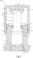
- the gas spring according to the invention comprises a hollow sliding element 1, provided with a first opening 14 that faces a first chamber 11, inside which a guide 2 is positioned, it also hollow; the first seals or sealing means 5 are placed on the internal surface 12 of the sliding element 1, facing the external surface 22 of the guide 2.
- a piston 3 is placed in the first chamber 11 of the sliding element 1, acting as limit, in order to prevent the sliding element 1-guide 2 system from slipping out; this piston 3 is provided with a head 31 and a stem 32; the latter is integral with a first wall 13 of the first chamber 11 in the position opposite to the first opening 14.
- the guide 2 serves as a constraint for the sliding of the stem 32 through a second opening 23, oriented towards the chamber 11, obtained at the top of the guide 2.
- the head 31 is instead constrained to slide in a second chamber 21 of the guide 2, and its diameter is greater than that of the stem 32; operatively, therefore, once the guide 2 is inserted into the sliding element 1, piston 3 is inserted into and fixed to the first wall 13.
- the first opening 14 has dimensions substantially corresponding to the first wall 13 so that the sliding element 1 is without a base and the seals 5 between the external walls 22 of the guide and the slider 1 itself are directly on the internal wall 12 of the latter.
- the first opening 14 is made in such a way that the slider 1 is completely bottomless; bottomless here means that the vertical walls 12 do not have any element projecting therefrom (apart from any seals or guiding means).
- a spring thus designed is easy to build and assemble as it eliminates the complicated sealing interactions between the seals usually fixed to the external wall of the piston and the internal wall of the chamber.
- the position and sliding mode of the upper element (in this case slider 1) on the external surface of the other element (the guide 2) creates protection against contaminants entering the chamber which is integrated with the spring, and is much more efficient and easier to implement than other solutions adopted in the known technique.
- the function of the head 31 can be performed by different elements, such as profiles and/or edges obtained on the surface of the stem 32 and/or chamber 21, which can in any case prevent the stem 32 from completely coming out of chamber 21 during the expansion of the gas spring.
- the sliding element 1 is constrained to move along the axis X of the guide 2 in relation to the latter.
- the travel is determined by the distance between the first abutments 210 of the chamber 21, in particular provided in the upper surface of the guide 2, and the head 31 of the piston 3, or between a second wall 211, opposite to such first abutments 210 and the head 31 itself.
- the excursion of the head 31 in the chamber 21 between the wall 211 and the abutments 210 can determine the travel of the sliding element 1 along the external surface 22 of the guide 2.
- the wall 13 of the sliding element can act as the lower limit, stopping its travel at the abutments 210 of the upper surface of the guide 2.
- a loading valve 6 for injecting the gas into the chambers 21 and 11, held in position by a locking ring 51.
- the total volume available to the gas therefore, is formed by both chambers 11 and 21, which are placed in communication by the existing play between the stem 32 of the piston 3 and the second opening 23.
- the operation of the gas spring 100 is based on the reciprocal sliding between the sliding element 1 and the guide 2, and between the stem 32 and the second opening 23;
- Figure 2 shows, in a schematic way to increase its intelligibility, the surfaces on which the gas pressure contained in chambers 11 and 21 exerts its force.
- these surfaces are:
- the sealing means are housed on the side surface of a piston, which looks like a relatively small element that slides on the internal walls of a chamber.
- the piston once compressed, the piston always has one face facing the inside of the chamber and one facing the intermediate vacuum environment.
- the reduced surface area of the piston is replaced by the larger surface area of the guide 2, facilitating reciprocal sliding and minimizing the probability of breakdowns or malfunction.
- the interface at the sealing means is exposed at all times to the pressure of the chamber on the one hand and the pressure of the external environment on the other.
- the total pressure difference at the interface therefore, is smaller, and this ensures a better seal, greater safety and also allows reducing the size of the seals to be installed.
- this solution makes it possible to carry out mechanical surface finish machining on the external surface 22 of the guide 2 in a simpler way than the machining of the internal walls, and with the possibility of obtaining higher degrees of finish.
- a gas spring of the type described has the additional advantage of also exploiting the external surface of the cylinder to increase the seal of the chamber; consequently, the average working pressure and the relative developed temperature are lower with respect to known springs, developed force being equal.
- the guide 2 may have a larger base 25 than the external surface 22 to act as the second limit of the slider 1 in order to further protect the gap between the external surface 22 of the guide 2 and the internal surface 12 of slider 1 itself.
- the sliding of the slider is interrupted at a certain distance from the support surface (equal to the height of the base of the guide) and, even in the presence of any oil or other elements on the surface, their entry into the gap is made less immediate.
- the gas is loaded into the chamber 11 via a first loading valve 6 and/or a second loading valve 61.
- the second valve 61 is placed along a wall of the chamber 11 adjacent to the external environment.
- the second loading valve 61 is placed in the wall 13; in order to allow the gas to reach the chamber 11, channels 62 are obtained inside the wall 13 itself so as to bypass the overall volume of the stem 32, which is also fixed to the wall 13.
- the second opening 23 may have guiding means 24 to improve the sliding of the stem 32 through it, ( Figure 3 ); similarly, the first opening 14 may also have guiding means 205 for the sliding of the sliding element 1 on the guide 2; in this case, it is possible to obtain two distinct sliding control positions of the sliding element 1 along the axis of the guide 2, avoiding the dangerous jamming phenomenon between the sliding element 1 and the guide 2 itself due to an offset between the two elements. Contrarily indeed, the spring would get jammed, subsequently causing a dangerous uncontrolled release of the sliding element due to the increase in gas pressure inside the chamber.
- this variant of the spring has two communicating chambers 11 and 21 contributes to the aforementioned objective of achieving greater efficiency and durability, spring size being equal.
- this contrivance it is possible to decrease the internal pressure since it is distributed on the walls of both chambers, unlike the known technique that provides for the various compartments to remain watertight, and therefore they must withstand greater stress.
- guiding means 105 in particular a stem guide, to the seals 5 on the internal wall 12 of the slider 1.
- Figure 4 shows a second variant of the invention.
- the gas spring 300 has substantially the same elements mentioned so far for the previous embodiments, which are in fact indicated by the same numerical references.
- seal 5 and the stem guide 305 are further protected against oil or dust infiltration by being completely recessed in the internal walls 12 of the chamber 11 of the slider 1.
- the sliding element 1 is constrained to slide along the axis X between a first end, comprising the wall 13 of slider 1 itself, and a second end comprising the head 31 of the piston 3, both constrained by the abutments 210 of the upper wall of the guide 2.
- the base 25 in this case is wider than the external walls 22 of the guide, but narrower than the overall dimensions of the sliding element 1 so that the lower protection 301, consisting essentially of the lower end of the wall 12, overhangs slightly from the base 25 itself.
- the base 25 is also completely open at the bottom so as to accommodate a closing element 326 adapted to fit into the base 25 itself once the piston 3 has been inserted into the chamber 21.
- the piston 3 is made in a single piece; moreover, the piston 3 has a cavity 33 that develops along the axis X.
- the gas spring becomes almost completely symmetrical in the arrangement of its parts, to the advantage of the construction simplicity and assembly of the parts.
Claims (7)
- Ressort à gaz (100) comprenant un premier élément (2), un deuxième élément (1), et une limite (3), dans lequel le deuxième élément (1) comprend une première chambre (11) et une première ouverture (14) pour accéder à la première chambre (11), le premier élément (2) peut être fixé à un plan de référence et comprend une seconde chambre (21), une seconde ouverture (23) pour accéder à la seconde chambre (21) et des parois externes (22), et est inséré dans la première chambre (11) du premier élément (2) à travers la première ouverture (14), dans lequel lesdits premier et second éléments (2, 1) sont mobiles et coulissent en va-et-vient le long d'un axe (X), dans lequel la limite (3) comprend une tige (32) et une tête (31) adaptées pour coulisser à travers la deuxième ouverture (23) dans la deuxième chambre (21) parallèlement à l'axe (X) de manière à limiter la course maximale du deuxième élément (1) au prolongement des parois externes (22) du premier élément (2), caractérisé en ce que lesdites première et seconde chambres (11, 21) communiquent à travers un jeu existant entre ladite tige (32) et ladite seconde ouverture (23), et le second élément (1) coulisse à travers la première ouverture (14) le long des parois externes (22) du premier élément (2).
- Ressort à gaz (100) selon la revendication 1, caractérisé en ce qu'il comprend des premiers moyens d'étanchéité ou joints (5) placés entre les parois externes (22) du premier élément (2) et une première surface interne (12) du deuxième élément (1).
- Ressort à gaz (100) selon l'une quelconque des revendications 1 ou 2, caractérisé en ce qu'il comprend une première soupape de chargement (6) pour charger un gaz dans le ressort (100), placée dans une deuxième surface interne (211) du premier élément (2).
- Ressort à gaz (100) selon l'une quelconque des revendications précédentes, caractérisé en ce que la limite (3) est solidaire du deuxième élément (1).
- Ressort à gaz (100) selon l'une quelconque des revendications précédentes, caractérisé en ce qu'il comprend des premiers moyens de guidage (24) pour guider la butée (3), placés entre la tige (32) de la butée (3) et la deuxième ouverture (23) du premier élément (2), et des deuxièmes moyens de guidage pour guider le deuxième élément (1), placés au niveau de la première ouverture (14).
- Ressort à gaz (100) selon l'une quelconque des revendications précédentes, caractérisé en ce que le deuxième élément (1) comprend une deuxième soupape de chargement (61).
- Ressort à gaz (100) selon la revendication 6, caractérisé en ce que le deuxième élément (1) comprend des canaux (62) pour relier la deuxième soupape de chargement (61) à la première chambre (11).
Applications Claiming Priority (2)
| Application Number | Priority Date | Filing Date | Title |
|---|---|---|---|
| IT102019000012786A IT201900012786A1 (it) | 2019-07-24 | 2019-07-24 | Molla a gas |
| PCT/IT2020/050183 WO2021014478A1 (fr) | 2019-07-24 | 2020-07-23 | Ressort à gaz |
Publications (3)
| Publication Number | Publication Date |
|---|---|
| EP4004398A1 EP4004398A1 (fr) | 2022-06-01 |
| EP4004398C0 EP4004398C0 (fr) | 2023-08-30 |
| EP4004398B1 true EP4004398B1 (fr) | 2023-08-30 |
Family
ID=68653527
Family Applications (1)
| Application Number | Title | Priority Date | Filing Date |
|---|---|---|---|
| EP20760569.2A Active EP4004398B1 (fr) | 2019-07-24 | 2020-07-23 | Ressort a gaz |
Country Status (12)
| Country | Link |
|---|---|
| US (1) | US20220275846A1 (fr) |
| EP (1) | EP4004398B1 (fr) |
| JP (1) | JP2022545165A (fr) |
| KR (1) | KR20220047582A (fr) |
| CN (1) | CN114207311A (fr) |
| AU (1) | AU2020319282A1 (fr) |
| BR (1) | BR112022000533A2 (fr) |
| CA (1) | CA3147329A1 (fr) |
| ES (1) | ES2958217T3 (fr) |
| IT (1) | IT201900012786A1 (fr) |
| MX (1) | MX2022000772A (fr) |
| WO (1) | WO2021014478A1 (fr) |
Family Cites Families (8)
| Publication number | Priority date | Publication date | Assignee | Title |
|---|---|---|---|---|
| US4249380A (en) * | 1979-07-25 | 1981-02-10 | Barry Wright Corporation | Two stage intensifier |
| US4550899A (en) * | 1980-08-21 | 1985-11-05 | Power Components Inc. | Pneumatic spring |
| DE3511554A1 (de) * | 1984-07-31 | 1986-02-13 | Hermann 5401 Bassenheim Krautkrämer | Gasfeder |
| DE19634680A1 (de) * | 1996-08-28 | 1998-03-12 | Kober Ag | Vorrichtung zur Überwindung von Reibungs- und Temperatureinflüssen an Gasfedern |
| ITPN20040074A1 (it) * | 2004-10-19 | 2005-01-19 | Silvano Bordignon | Molla pneumatica con corsa guidata |
| ES2348903B1 (es) * | 2010-07-16 | 2011-10-14 | Azol-Gas, S.L. | Resorte de gas telescópico. |
| FR3036655B1 (fr) * | 2015-05-26 | 2018-11-02 | Olivier Bossard | Systeme de suspension pneumatique |
| CN207485941U (zh) * | 2017-10-31 | 2018-06-12 | 常州市南泰气弹簧有限公司 | 防转气弹簧 |
-
2019
- 2019-07-24 IT IT102019000012786A patent/IT201900012786A1/it unknown
-
2020
- 2020-07-23 KR KR1020227006252A patent/KR20220047582A/ko unknown
- 2020-07-23 MX MX2022000772A patent/MX2022000772A/es unknown
- 2020-07-23 BR BR112022000533A patent/BR112022000533A2/pt unknown
- 2020-07-23 AU AU2020319282A patent/AU2020319282A1/en active Pending
- 2020-07-23 CA CA3147329A patent/CA3147329A1/fr active Pending
- 2020-07-23 JP JP2022504558A patent/JP2022545165A/ja active Pending
- 2020-07-23 EP EP20760569.2A patent/EP4004398B1/fr active Active
- 2020-07-23 ES ES20760569T patent/ES2958217T3/es active Active
- 2020-07-23 CN CN202080053462.3A patent/CN114207311A/zh active Pending
- 2020-07-23 US US17/626,276 patent/US20220275846A1/en active Pending
- 2020-07-23 WO PCT/IT2020/050183 patent/WO2021014478A1/fr active Application Filing
Also Published As
| Publication number | Publication date |
|---|---|
| EP4004398C0 (fr) | 2023-08-30 |
| CA3147329A1 (fr) | 2021-01-28 |
| MX2022000772A (es) | 2022-04-26 |
| WO2021014478A9 (fr) | 2022-02-10 |
| ES2958217T3 (es) | 2024-02-05 |
| BR112022000533A2 (pt) | 2022-04-12 |
| IT201900012786A1 (it) | 2021-01-24 |
| WO2021014478A1 (fr) | 2021-01-28 |
| US20220275846A1 (en) | 2022-09-01 |
| EP4004398A1 (fr) | 2022-06-01 |
| KR20220047582A (ko) | 2022-04-18 |
| CN114207311A (zh) | 2022-03-18 |
| JP2022545165A (ja) | 2022-10-26 |
| AU2020319282A1 (en) | 2022-02-17 |
Similar Documents
| Publication | Publication Date | Title |
|---|---|---|
| KR20040012501A (ko) | 피스톤-실린더-유닛 | |
| JP3856155B2 (ja) | 牽引機構のための液圧式緊締装置 | |
| KR102164909B1 (ko) | 직선 운동 로드의 록 장치 | |
| US20050265868A1 (en) | Fluid actuator | |
| RU2717469C1 (ru) | Гидро(пневмо)устройство | |
| KR20010087319A (ko) | 쿠션기구부착 로터리 액츄에이터 | |
| US8261710B2 (en) | Sealed lash adjuster and seal structure between first and second parts | |
| CN110199096B (zh) | 长度能调节的连杆,其具有带多个活塞密封件的缸-活塞单元 | |
| EP4004398B1 (fr) | Ressort a gaz | |
| JP2006052848A (ja) | 低衝撃気体ばね | |
| KR20090028458A (ko) | 가이드를 구비한 가스 스프링 | |
| TWI388751B (zh) | 具備低滑動阻力的墊片之流體壓力機器 | |
| RU2606714C2 (ru) | Клапан с герметичным уплотнением штока | |
| GB2330643A (en) | Piston-cylinder assembly | |
| CN111664232A (zh) | 具有筒体的密封张紧器 | |
| US8323137B2 (en) | Hydraulic tensioning element for a traction mechanism drive | |
| US20100075790A1 (en) | Hydraulic tensioning element for a traction mechanism drive | |
| RU2803612C2 (ru) | Газовая пружина | |
| US4778351A (en) | Unloader, and in combination with an air compressor inlet housing | |
| AU4760199A (en) | Valve system | |
| JP4537418B2 (ja) | 密封型ラッシュアジャスタ | |
| EP3673179B1 (fr) | Agencement de roulements d'actionneur | |
| US6769350B2 (en) | Linear path slide | |
| KR102040485B1 (ko) | 플로어 힌지의 피스톤 변형방지 구조 | |
| JP2011094798A (ja) | チェックリングを含む油圧シリンダクッション装置 |
Legal Events
| Date | Code | Title | Description |
|---|---|---|---|
| STAA | Information on the status of an ep patent application or granted ep patent |
Free format text: STATUS: UNKNOWN |
|
| STAA | Information on the status of an ep patent application or granted ep patent |
Free format text: STATUS: THE INTERNATIONAL PUBLICATION HAS BEEN MADE |
|
| PUAI | Public reference made under article 153(3) epc to a published international application that has entered the european phase |
Free format text: ORIGINAL CODE: 0009012 |
|
| STAA | Information on the status of an ep patent application or granted ep patent |
Free format text: STATUS: REQUEST FOR EXAMINATION WAS MADE |
|
| 17P | Request for examination filed |
Effective date: 20220215 |
|
| AK | Designated contracting states |
Kind code of ref document: A1 Designated state(s): AL AT BE BG CH CY CZ DE DK EE ES FI FR GB GR HR HU IE IS IT LI LT LU LV MC MK MT NL NO PL PT RO RS SE SI SK SM TR |
|
| DAV | Request for validation of the european patent (deleted) | ||
| DAX | Request for extension of the european patent (deleted) | ||
| GRAP | Despatch of communication of intention to grant a patent |
Free format text: ORIGINAL CODE: EPIDOSNIGR1 |
|
| STAA | Information on the status of an ep patent application or granted ep patent |
Free format text: STATUS: GRANT OF PATENT IS INTENDED |
|
| INTG | Intention to grant announced |
Effective date: 20230404 |
|
| GRAS | Grant fee paid |
Free format text: ORIGINAL CODE: EPIDOSNIGR3 |
|
| GRAA | (expected) grant |
Free format text: ORIGINAL CODE: 0009210 |
|
| STAA | Information on the status of an ep patent application or granted ep patent |
Free format text: STATUS: THE PATENT HAS BEEN GRANTED |
|
| AK | Designated contracting states |
Kind code of ref document: B1 Designated state(s): AL AT BE BG CH CY CZ DE DK EE ES FI FR GB GR HR HU IE IS IT LI LT LU LV MC MK MT NL NO PL PT RO RS SE SI SK SM TR |
|
| REG | Reference to a national code |
Ref country code: GB Ref legal event code: FG4D |
|
| REG | Reference to a national code |
Ref country code: CH Ref legal event code: EP |
|
| REG | Reference to a national code |
Ref country code: DE Ref legal event code: R096 Ref document number: 602020016843 Country of ref document: DE |
|
| REG | Reference to a national code |
Ref country code: IE Ref legal event code: FG4D |
|
| U01 | Request for unitary effect filed |
Effective date: 20230927 |
|
| U07 | Unitary effect registered |
Designated state(s): AT BE BG DE DK EE FI FR IT LT LU LV MT NL PT SE SI Effective date: 20231005 |
|
| PG25 | Lapsed in a contracting state [announced via postgrant information from national office to epo] |
Ref country code: GR Free format text: LAPSE BECAUSE OF FAILURE TO SUBMIT A TRANSLATION OF THE DESCRIPTION OR TO PAY THE FEE WITHIN THE PRESCRIBED TIME-LIMIT Effective date: 20231201 |
|
| PG25 | Lapsed in a contracting state [announced via postgrant information from national office to epo] |
Ref country code: IS Free format text: LAPSE BECAUSE OF FAILURE TO SUBMIT A TRANSLATION OF THE DESCRIPTION OR TO PAY THE FEE WITHIN THE PRESCRIBED TIME-LIMIT Effective date: 20231230 |
|
| PG25 | Lapsed in a contracting state [announced via postgrant information from national office to epo] |
Ref country code: RS Free format text: LAPSE BECAUSE OF FAILURE TO SUBMIT A TRANSLATION OF THE DESCRIPTION OR TO PAY THE FEE WITHIN THE PRESCRIBED TIME-LIMIT Effective date: 20230830 Ref country code: NO Free format text: LAPSE BECAUSE OF FAILURE TO SUBMIT A TRANSLATION OF THE DESCRIPTION OR TO PAY THE FEE WITHIN THE PRESCRIBED TIME-LIMIT Effective date: 20231130 Ref country code: IS Free format text: LAPSE BECAUSE OF FAILURE TO SUBMIT A TRANSLATION OF THE DESCRIPTION OR TO PAY THE FEE WITHIN THE PRESCRIBED TIME-LIMIT Effective date: 20231230 Ref country code: HR Free format text: LAPSE BECAUSE OF FAILURE TO SUBMIT A TRANSLATION OF THE DESCRIPTION OR TO PAY THE FEE WITHIN THE PRESCRIBED TIME-LIMIT Effective date: 20230830 Ref country code: GR Free format text: LAPSE BECAUSE OF FAILURE TO SUBMIT A TRANSLATION OF THE DESCRIPTION OR TO PAY THE FEE WITHIN THE PRESCRIBED TIME-LIMIT Effective date: 20231201 |
|
| PG25 | Lapsed in a contracting state [announced via postgrant information from national office to epo] |
Ref country code: PL Free format text: LAPSE BECAUSE OF FAILURE TO SUBMIT A TRANSLATION OF THE DESCRIPTION OR TO PAY THE FEE WITHIN THE PRESCRIBED TIME-LIMIT Effective date: 20230830 |
|
| PG25 | Lapsed in a contracting state [announced via postgrant information from national office to epo] |
Ref country code: SM Free format text: LAPSE BECAUSE OF FAILURE TO SUBMIT A TRANSLATION OF THE DESCRIPTION OR TO PAY THE FEE WITHIN THE PRESCRIBED TIME-LIMIT Effective date: 20230830 Ref country code: RO Free format text: LAPSE BECAUSE OF FAILURE TO SUBMIT A TRANSLATION OF THE DESCRIPTION OR TO PAY THE FEE WITHIN THE PRESCRIBED TIME-LIMIT Effective date: 20230830 Ref country code: CZ Free format text: LAPSE BECAUSE OF FAILURE TO SUBMIT A TRANSLATION OF THE DESCRIPTION OR TO PAY THE FEE WITHIN THE PRESCRIBED TIME-LIMIT Effective date: 20230830 Ref country code: SK Free format text: LAPSE BECAUSE OF FAILURE TO SUBMIT A TRANSLATION OF THE DESCRIPTION OR TO PAY THE FEE WITHIN THE PRESCRIBED TIME-LIMIT Effective date: 20230830 |