EP4004256B1 - Multilayered nickel-phosphorus composite - Google Patents
Multilayered nickel-phosphorus composite Download PDFInfo
- Publication number
- EP4004256B1 EP4004256B1 EP20747144.2A EP20747144A EP4004256B1 EP 4004256 B1 EP4004256 B1 EP 4004256B1 EP 20747144 A EP20747144 A EP 20747144A EP 4004256 B1 EP4004256 B1 EP 4004256B1
- Authority
- EP
- European Patent Office
- Prior art keywords
- composite
- layer
- metallic
- nip
- nip layer
- Prior art date
- Legal status (The legal status is an assumption and is not a legal conclusion. Google has not performed a legal analysis and makes no representation as to the accuracy of the status listed.)
- Active
Links
- 239000002131 composite material Substances 0.000 title claims description 109
- OFNHPGDEEMZPFG-UHFFFAOYSA-N phosphanylidynenickel Chemical compound [P].[Ni] OFNHPGDEEMZPFG-UHFFFAOYSA-N 0.000 title description 2
- 239000002245 particle Substances 0.000 claims description 84
- 238000000576 coating method Methods 0.000 claims description 64
- 239000011248 coating agent Substances 0.000 claims description 43
- 239000000758 substrate Substances 0.000 claims description 43
- 229910052759 nickel Inorganic materials 0.000 claims description 26
- 229910052698 phosphorus Inorganic materials 0.000 claims description 25
- 230000008021 deposition Effects 0.000 claims description 23
- 239000000203 mixture Substances 0.000 claims description 20
- 229910052580 B4C Inorganic materials 0.000 claims description 18
- 238000000034 method Methods 0.000 claims description 18
- 239000011159 matrix material Substances 0.000 claims description 16
- 229910052751 metal Inorganic materials 0.000 claims description 15
- 238000007669 thermal treatment Methods 0.000 claims description 9
- 238000010438 heat treatment Methods 0.000 claims description 7
- 238000002360 preparation method Methods 0.000 claims description 7
- INAHAJYZKVIDIZ-UHFFFAOYSA-N boron carbide Chemical compound B12B3B4C32B41 INAHAJYZKVIDIZ-UHFFFAOYSA-N 0.000 claims description 6
- 230000015556 catabolic process Effects 0.000 claims description 3
- 238000006731 degradation reaction Methods 0.000 claims description 3
- 239000000126 substance Substances 0.000 claims description 2
- 239000005543 nano-size silicon particle Substances 0.000 claims 1
- 239000010410 layer Substances 0.000 description 122
- 229910010271 silicon carbide Inorganic materials 0.000 description 28
- PXHVJJICTQNCMI-UHFFFAOYSA-N nickel Substances [Ni] PXHVJJICTQNCMI-UHFFFAOYSA-N 0.000 description 24
- HBMJWWWQQXIZIP-UHFFFAOYSA-N silicon carbide Chemical compound [Si+]#[C-] HBMJWWWQQXIZIP-UHFFFAOYSA-N 0.000 description 24
- 238000000151 deposition Methods 0.000 description 20
- 238000005260 corrosion Methods 0.000 description 19
- 230000007797 corrosion Effects 0.000 description 18
- 230000003628 erosive effect Effects 0.000 description 17
- 229910000831 Steel Inorganic materials 0.000 description 16
- 239000010959 steel Substances 0.000 description 16
- 239000000243 solution Substances 0.000 description 11
- 239000007789 gas Substances 0.000 description 9
- 238000007747 plating Methods 0.000 description 9
- 239000002002 slurry Substances 0.000 description 9
- 239000000463 material Substances 0.000 description 7
- 239000002184 metal Substances 0.000 description 7
- 239000007787 solid Substances 0.000 description 7
- 238000005299 abrasion Methods 0.000 description 6
- 230000004913 activation Effects 0.000 description 6
- XLYOFNOQVPJJNP-UHFFFAOYSA-N water Substances O XLYOFNOQVPJJNP-UHFFFAOYSA-N 0.000 description 6
- 239000000919 ceramic Substances 0.000 description 5
- 238000002156 mixing Methods 0.000 description 5
- 239000003921 oil Substances 0.000 description 5
- KDLHZDBZIXYQEI-UHFFFAOYSA-N Palladium Chemical compound [Pd] KDLHZDBZIXYQEI-UHFFFAOYSA-N 0.000 description 4
- 229910045601 alloy Inorganic materials 0.000 description 4
- 239000000956 alloy Substances 0.000 description 4
- 238000012512 characterization method Methods 0.000 description 4
- 238000007772 electroless plating Methods 0.000 description 4
- 239000007788 liquid Substances 0.000 description 4
- 239000002105 nanoparticle Substances 0.000 description 4
- 239000004576 sand Substances 0.000 description 4
- CSCPPACGZOOCGX-UHFFFAOYSA-N Acetone Chemical compound CC(C)=O CSCPPACGZOOCGX-UHFFFAOYSA-N 0.000 description 3
- OKTJSMMVPCPJKN-UHFFFAOYSA-N Carbon Chemical compound [C] OKTJSMMVPCPJKN-UHFFFAOYSA-N 0.000 description 3
- CURLTUGMZLYLDI-UHFFFAOYSA-N Carbon dioxide Chemical compound O=C=O CURLTUGMZLYLDI-UHFFFAOYSA-N 0.000 description 3
- 229910000975 Carbon steel Inorganic materials 0.000 description 3
- RYGMFSIKBFXOCR-UHFFFAOYSA-N Copper Chemical compound [Cu] RYGMFSIKBFXOCR-UHFFFAOYSA-N 0.000 description 3
- 229910018104 Ni-P Inorganic materials 0.000 description 3
- 229910018536 Ni—P Inorganic materials 0.000 description 3
- 239000008186 active pharmaceutical agent Substances 0.000 description 3
- 230000015572 biosynthetic process Effects 0.000 description 3
- 239000010962 carbon steel Substances 0.000 description 3
- 229910052802 copper Inorganic materials 0.000 description 3
- 239000010949 copper Substances 0.000 description 3
- 239000012925 reference material Substances 0.000 description 3
- 150000003839 salts Chemical class 0.000 description 3
- WFKWXMTUELFFGS-UHFFFAOYSA-N tungsten Chemical compound [W] WFKWXMTUELFFGS-UHFFFAOYSA-N 0.000 description 3
- 229910052721 tungsten Inorganic materials 0.000 description 3
- 239000010937 tungsten Substances 0.000 description 3
- IJGRMHOSHXDMSA-UHFFFAOYSA-N Atomic nitrogen Chemical compound N#N IJGRMHOSHXDMSA-UHFFFAOYSA-N 0.000 description 2
- RWSOTUBLDIXVET-UHFFFAOYSA-N Dihydrogen sulfide Chemical compound S RWSOTUBLDIXVET-UHFFFAOYSA-N 0.000 description 2
- XEEYBQQBJWHFJM-UHFFFAOYSA-N Iron Chemical compound [Fe] XEEYBQQBJWHFJM-UHFFFAOYSA-N 0.000 description 2
- FAPWRFPIFSIZLT-UHFFFAOYSA-M Sodium chloride Chemical compound [Na+].[Cl-] FAPWRFPIFSIZLT-UHFFFAOYSA-M 0.000 description 2
- MCMNRKCIXSYSNV-UHFFFAOYSA-N Zirconium dioxide Chemical compound O=[Zr]=O MCMNRKCIXSYSNV-UHFFFAOYSA-N 0.000 description 2
- 229910052799 carbon Inorganic materials 0.000 description 2
- 229910002092 carbon dioxide Inorganic materials 0.000 description 2
- 239000010941 cobalt Substances 0.000 description 2
- 229910017052 cobalt Inorganic materials 0.000 description 2
- GUTLYIVDDKVIGB-UHFFFAOYSA-N cobalt atom Chemical compound [Co] GUTLYIVDDKVIGB-UHFFFAOYSA-N 0.000 description 2
- 229910003460 diamond Inorganic materials 0.000 description 2
- 239000010432 diamond Substances 0.000 description 2
- 238000009826 distribution Methods 0.000 description 2
- 229920001971 elastomer Polymers 0.000 description 2
- 239000003792 electrolyte Substances 0.000 description 2
- 229910000037 hydrogen sulfide Inorganic materials 0.000 description 2
- 238000010191 image analysis Methods 0.000 description 2
- 238000007654 immersion Methods 0.000 description 2
- 229910001092 metal group alloy Inorganic materials 0.000 description 2
- 238000000386 microscopy Methods 0.000 description 2
- 230000003287 optical effect Effects 0.000 description 2
- 239000013618 particulate matter Substances 0.000 description 2
- 239000004033 plastic Substances 0.000 description 2
- 229920003023 plastic Polymers 0.000 description 2
- 238000007639 printing Methods 0.000 description 2
- 239000000725 suspension Substances 0.000 description 2
- UONOETXJSWQNOL-UHFFFAOYSA-N tungsten carbide Chemical compound [W+]#[C-] UONOETXJSWQNOL-UHFFFAOYSA-N 0.000 description 2
- 229910000838 Al alloy Inorganic materials 0.000 description 1
- 229910052582 BN Inorganic materials 0.000 description 1
- PZNSFCLAULLKQX-UHFFFAOYSA-N Boron nitride Chemical compound N#B PZNSFCLAULLKQX-UHFFFAOYSA-N 0.000 description 1
- 229910001369 Brass Inorganic materials 0.000 description 1
- 229910000906 Bronze Inorganic materials 0.000 description 1
- VYZAMTAEIAYCRO-UHFFFAOYSA-N Chromium Chemical compound [Cr] VYZAMTAEIAYCRO-UHFFFAOYSA-N 0.000 description 1
- UFHFLCQGNIYNRP-UHFFFAOYSA-N Hydrogen Chemical compound [H][H] UFHFLCQGNIYNRP-UHFFFAOYSA-N 0.000 description 1
- 229910000990 Ni alloy Inorganic materials 0.000 description 1
- 229910001096 P alloy Inorganic materials 0.000 description 1
- OAICVXFJPJFONN-UHFFFAOYSA-N Phosphorus Chemical compound [P] OAICVXFJPJFONN-UHFFFAOYSA-N 0.000 description 1
- 229910052581 Si3N4 Inorganic materials 0.000 description 1
- XUIMIQQOPSSXEZ-UHFFFAOYSA-N Silicon Chemical compound [Si] XUIMIQQOPSSXEZ-UHFFFAOYSA-N 0.000 description 1
- QAOWNCQODCNURD-UHFFFAOYSA-L Sulfate Chemical compound [O-]S([O-])(=O)=O QAOWNCQODCNURD-UHFFFAOYSA-L 0.000 description 1
- QAOWNCQODCNURD-UHFFFAOYSA-N Sulfuric acid Chemical compound OS(O)(=O)=O QAOWNCQODCNURD-UHFFFAOYSA-N 0.000 description 1
- 229910001069 Ti alloy Inorganic materials 0.000 description 1
- RTAQQCXQSZGOHL-UHFFFAOYSA-N Titanium Chemical compound [Ti] RTAQQCXQSZGOHL-UHFFFAOYSA-N 0.000 description 1
- NRTOMJZYCJJWKI-UHFFFAOYSA-N Titanium nitride Chemical compound [Ti]#N NRTOMJZYCJJWKI-UHFFFAOYSA-N 0.000 description 1
- 229910026551 ZrC Inorganic materials 0.000 description 1
- OTCHGXYCWNXDOA-UHFFFAOYSA-N [C].[Zr] Chemical compound [C].[Zr] OTCHGXYCWNXDOA-UHFFFAOYSA-N 0.000 description 1
- 239000006096 absorbing agent Substances 0.000 description 1
- 229910002065 alloy metal Inorganic materials 0.000 description 1
- 239000004411 aluminium Substances 0.000 description 1
- 229910052782 aluminium Inorganic materials 0.000 description 1
- XAGFODPZIPBFFR-UHFFFAOYSA-N aluminium Chemical compound [Al] XAGFODPZIPBFFR-UHFFFAOYSA-N 0.000 description 1
- PNEYBMLMFCGWSK-UHFFFAOYSA-N aluminium oxide Inorganic materials [O-2].[O-2].[O-2].[Al+3].[Al+3] PNEYBMLMFCGWSK-UHFFFAOYSA-N 0.000 description 1
- 239000010951 brass Substances 0.000 description 1
- 239000010974 bronze Substances 0.000 description 1
- 239000001569 carbon dioxide Substances 0.000 description 1
- 239000003054 catalyst Substances 0.000 description 1
- 229910010293 ceramic material Inorganic materials 0.000 description 1
- 150000003841 chloride salts Chemical class 0.000 description 1
- 229910052804 chromium Inorganic materials 0.000 description 1
- 239000011651 chromium Substances 0.000 description 1
- 238000004140 cleaning Methods 0.000 description 1
- 239000011247 coating layer Substances 0.000 description 1
- 239000004020 conductor Substances 0.000 description 1
- KUNSUQLRTQLHQQ-UHFFFAOYSA-N copper tin Chemical compound [Cu].[Sn] KUNSUQLRTQLHQQ-UHFFFAOYSA-N 0.000 description 1
- 238000005238 degreasing Methods 0.000 description 1
- 238000005137 deposition process Methods 0.000 description 1
- 239000006185 dispersion Substances 0.000 description 1
- 238000005516 engineering process Methods 0.000 description 1
- 238000005530 etching Methods 0.000 description 1
- 239000004744 fabric Substances 0.000 description 1
- 239000012530 fluid Substances 0.000 description 1
- 239000004811 fluoropolymer Substances 0.000 description 1
- 229920002313 fluoropolymer Polymers 0.000 description 1
- 238000009472 formulation Methods 0.000 description 1
- 229910002804 graphite Inorganic materials 0.000 description 1
- 239000010439 graphite Substances 0.000 description 1
- 238000009499 grossing Methods 0.000 description 1
- 238000007542 hardness measurement Methods 0.000 description 1
- 229910000856 hastalloy Inorganic materials 0.000 description 1
- 229910052739 hydrogen Inorganic materials 0.000 description 1
- 239000001257 hydrogen Substances 0.000 description 1
- 238000007373 indentation Methods 0.000 description 1
- 239000003112 inhibitor Substances 0.000 description 1
- 239000012212 insulator Substances 0.000 description 1
- 229910000765 intermetallic Inorganic materials 0.000 description 1
- 229910052742 iron Inorganic materials 0.000 description 1
- 230000001788 irregular Effects 0.000 description 1
- 238000005259 measurement Methods 0.000 description 1
- 150000001247 metal acetylides Chemical class 0.000 description 1
- 239000007769 metal material Substances 0.000 description 1
- 150000002739 metals Chemical class 0.000 description 1
- 239000011859 microparticle Substances 0.000 description 1
- 238000005065 mining Methods 0.000 description 1
- 229910003465 moissanite Inorganic materials 0.000 description 1
- 230000000877 morphologic effect Effects 0.000 description 1
- 229910052757 nitrogen Inorganic materials 0.000 description 1
- 239000000615 nonconductor Substances 0.000 description 1
- 229910052763 palladium Inorganic materials 0.000 description 1
- 239000011236 particulate material Substances 0.000 description 1
- 239000011574 phosphorus Substances 0.000 description 1
- 229920001084 poly(chloroprene) Polymers 0.000 description 1
- 239000000843 powder Substances 0.000 description 1
- 238000010248 power generation Methods 0.000 description 1
- 239000012266 salt solution Substances 0.000 description 1
- 238000001878 scanning electron micrograph Methods 0.000 description 1
- 239000010703 silicon Substances 0.000 description 1
- 229910052710 silicon Inorganic materials 0.000 description 1
- HQVNEWCFYHHQES-UHFFFAOYSA-N silicon nitride Chemical compound N12[Si]34N5[Si]62N3[Si]51N64 HQVNEWCFYHHQES-UHFFFAOYSA-N 0.000 description 1
- 239000011780 sodium chloride Substances 0.000 description 1
- 239000010935 stainless steel Substances 0.000 description 1
- 229910001220 stainless steel Inorganic materials 0.000 description 1
- 238000010561 standard procedure Methods 0.000 description 1
- 229910021653 sulphate ion Inorganic materials 0.000 description 1
- 239000001117 sulphuric acid Substances 0.000 description 1
- 235000011149 sulphuric acid Nutrition 0.000 description 1
- 239000004094 surface-active agent Substances 0.000 description 1
- 239000010936 titanium Substances 0.000 description 1
- 229910052719 titanium Inorganic materials 0.000 description 1
- 238000005406 washing Methods 0.000 description 1
- 230000004580 weight loss Effects 0.000 description 1
Images

Classifications
-
- C—CHEMISTRY; METALLURGY
- C23—COATING METALLIC MATERIAL; COATING MATERIAL WITH METALLIC MATERIAL; CHEMICAL SURFACE TREATMENT; DIFFUSION TREATMENT OF METALLIC MATERIAL; COATING BY VACUUM EVAPORATION, BY SPUTTERING, BY ION IMPLANTATION OR BY CHEMICAL VAPOUR DEPOSITION, IN GENERAL; INHIBITING CORROSION OF METALLIC MATERIAL OR INCRUSTATION IN GENERAL
- C23C—COATING METALLIC MATERIAL; COATING MATERIAL WITH METALLIC MATERIAL; SURFACE TREATMENT OF METALLIC MATERIAL BY DIFFUSION INTO THE SURFACE, BY CHEMICAL CONVERSION OR SUBSTITUTION; COATING BY VACUUM EVAPORATION, BY SPUTTERING, BY ION IMPLANTATION OR BY CHEMICAL VAPOUR DEPOSITION, IN GENERAL
- C23C18/00—Chemical coating by decomposition of either liquid compounds or solutions of the coating forming compounds, without leaving reaction products of surface material in the coating; Contact plating
- C23C18/16—Chemical coating by decomposition of either liquid compounds or solutions of the coating forming compounds, without leaving reaction products of surface material in the coating; Contact plating by reduction or substitution, e.g. electroless plating
- C23C18/1601—Process or apparatus
- C23C18/1633—Process of electroless plating
- C23C18/1646—Characteristics of the product obtained
- C23C18/165—Multilayered product
- C23C18/1651—Two or more layers only obtained by electroless plating
-
- B—PERFORMING OPERATIONS; TRANSPORTING
- B32—LAYERED PRODUCTS
- B32B—LAYERED PRODUCTS, i.e. PRODUCTS BUILT-UP OF STRATA OF FLAT OR NON-FLAT, e.g. CELLULAR OR HONEYCOMB, FORM
- B32B15/00—Layered products comprising a layer of metal
- B32B15/04—Layered products comprising a layer of metal comprising metal as the main or only constituent of a layer, which is next to another layer of the same or of a different material
- B32B15/043—Layered products comprising a layer of metal comprising metal as the main or only constituent of a layer, which is next to another layer of the same or of a different material of metal
-
- C—CHEMISTRY; METALLURGY
- C23—COATING METALLIC MATERIAL; COATING MATERIAL WITH METALLIC MATERIAL; CHEMICAL SURFACE TREATMENT; DIFFUSION TREATMENT OF METALLIC MATERIAL; COATING BY VACUUM EVAPORATION, BY SPUTTERING, BY ION IMPLANTATION OR BY CHEMICAL VAPOUR DEPOSITION, IN GENERAL; INHIBITING CORROSION OF METALLIC MATERIAL OR INCRUSTATION IN GENERAL
- C23C—COATING METALLIC MATERIAL; COATING MATERIAL WITH METALLIC MATERIAL; SURFACE TREATMENT OF METALLIC MATERIAL BY DIFFUSION INTO THE SURFACE, BY CHEMICAL CONVERSION OR SUBSTITUTION; COATING BY VACUUM EVAPORATION, BY SPUTTERING, BY ION IMPLANTATION OR BY CHEMICAL VAPOUR DEPOSITION, IN GENERAL
- C23C18/00—Chemical coating by decomposition of either liquid compounds or solutions of the coating forming compounds, without leaving reaction products of surface material in the coating; Contact plating
- C23C18/16—Chemical coating by decomposition of either liquid compounds or solutions of the coating forming compounds, without leaving reaction products of surface material in the coating; Contact plating by reduction or substitution, e.g. electroless plating
- C23C18/1601—Process or apparatus
- C23C18/1633—Process of electroless plating
- C23C18/1655—Process features
- C23C18/1662—Use of incorporated material in the solution or dispersion, e.g. particles, whiskers, wires
-
- C—CHEMISTRY; METALLURGY
- C23—COATING METALLIC MATERIAL; COATING MATERIAL WITH METALLIC MATERIAL; CHEMICAL SURFACE TREATMENT; DIFFUSION TREATMENT OF METALLIC MATERIAL; COATING BY VACUUM EVAPORATION, BY SPUTTERING, BY ION IMPLANTATION OR BY CHEMICAL VAPOUR DEPOSITION, IN GENERAL; INHIBITING CORROSION OF METALLIC MATERIAL OR INCRUSTATION IN GENERAL
- C23C—COATING METALLIC MATERIAL; COATING MATERIAL WITH METALLIC MATERIAL; SURFACE TREATMENT OF METALLIC MATERIAL BY DIFFUSION INTO THE SURFACE, BY CHEMICAL CONVERSION OR SUBSTITUTION; COATING BY VACUUM EVAPORATION, BY SPUTTERING, BY ION IMPLANTATION OR BY CHEMICAL VAPOUR DEPOSITION, IN GENERAL
- C23C18/00—Chemical coating by decomposition of either liquid compounds or solutions of the coating forming compounds, without leaving reaction products of surface material in the coating; Contact plating
- C23C18/16—Chemical coating by decomposition of either liquid compounds or solutions of the coating forming compounds, without leaving reaction products of surface material in the coating; Contact plating by reduction or substitution, e.g. electroless plating
- C23C18/1601—Process or apparatus
- C23C18/1633—Process of electroless plating
- C23C18/1689—After-treatment
- C23C18/1692—Heat-treatment
-
- C—CHEMISTRY; METALLURGY
- C23—COATING METALLIC MATERIAL; COATING MATERIAL WITH METALLIC MATERIAL; CHEMICAL SURFACE TREATMENT; DIFFUSION TREATMENT OF METALLIC MATERIAL; COATING BY VACUUM EVAPORATION, BY SPUTTERING, BY ION IMPLANTATION OR BY CHEMICAL VAPOUR DEPOSITION, IN GENERAL; INHIBITING CORROSION OF METALLIC MATERIAL OR INCRUSTATION IN GENERAL
- C23C—COATING METALLIC MATERIAL; COATING MATERIAL WITH METALLIC MATERIAL; SURFACE TREATMENT OF METALLIC MATERIAL BY DIFFUSION INTO THE SURFACE, BY CHEMICAL CONVERSION OR SUBSTITUTION; COATING BY VACUUM EVAPORATION, BY SPUTTERING, BY ION IMPLANTATION OR BY CHEMICAL VAPOUR DEPOSITION, IN GENERAL
- C23C18/00—Chemical coating by decomposition of either liquid compounds or solutions of the coating forming compounds, without leaving reaction products of surface material in the coating; Contact plating
- C23C18/16—Chemical coating by decomposition of either liquid compounds or solutions of the coating forming compounds, without leaving reaction products of surface material in the coating; Contact plating by reduction or substitution, e.g. electroless plating
- C23C18/31—Coating with metals
- C23C18/32—Coating with nickel, cobalt or mixtures thereof with phosphorus or boron
Definitions
- the invention provides a system comprising a substrate and an electroless composite coating comprising a layered structure alternating a metallic NiP layer and a composite NiP layer.
- the invention further pertains to the method of preparation of said system and to its uses.
- Solid particle erosion is material removal/damage to a solid surface produced by repeated impacts of solid particles. It is to be expected whenever hard particles are entrained in a gas or liquid medium impinging on a solid at any significant velocity.
- the solid-liquid erosion is known as slurry erosion. Slurry erosion has become a serious problem for the performance, reliability, and service life of slurry equipment used in many industrial applications such as: mining machinery components, hydraulic transport of solids in pipelines, marine, oil gas and power generation industries.
- Electroless Ni-P coatings have been well known as a hard coating for industrial applications, due to their good corrosion and wear resistance properties. They are usually obtained by co-depositing particulate materials, such as ceramics, diamond and fluoropolymers and carbides of silicon, tungsten and chromium. This valuable process can coat not only electrically conductive materials including graphite but also fabrics, insulators like plastics, rubber etc.
- electroless Ni-composite plated substrates examples include US 2009/0011136 , US 20111/0162751 , US2013/0143031 , and US2016/0010214 .
- US4358923A discloses processes and articles for composite electroless coatings comprising at least two distinct layers, the first layer comprising a metal and/or a metal alloy plus particulate matter and the second layer comprising a metal and/or a metal alloy and being substantially free of particulate matter.
- US2011226144A1 discloses a doctor blade for wiping printing ink off a surface of a printing plate and/or for use as a paper doctor knife; at least the working edge region of the doctor blade is covered with a coating on the basis of a nickel-phosphorus alloy; in some embodiments, the coating comprises a composite layer of NiP, containing particles of different size and nature, and a metallic layer of NiP.
- the major advantages of the electroless Ni-P plating deposition process include the formation of a uniform deposit on irregular surfaces, direct deposition on surface-activated non-conductors, and the formation of non-magnetic, low internal stress deposits. Furthermore, when accompanied by an appropriate post-heat treatment, the wear resistance of the coatings can be improved considerably. The effectiveness of using a composite electroless Ni-P-SiC coating system for cavitation erosion protection of steel has also been observed.
- the main application of the electroless Ni-P coatings is in the increase of wear resistance of parts in choke valves and in the protection of the inner/outer surface of the pipelines.
- Pipelines play an important role throughout the world as a means of transporting gases and liquids over long distances from their source to the supply. According to the environment and to the fluid, abrasion and erosion phenomena can degrade rapidly the wall of the pipeline, losing integrity. Hence, in the oil and gas field, in particular for the coating of the inner surfaces of the pipelines, a very high wear (abrasive/erosive) resistance is required combined with an improved corrosion protection to harsh environment. However, the combination of these two properties is hard to achieve through the traditional and commercially available technology of composite electroless deposition.
- the present invention relates to a system comprising a substrate and an electroless composite coating in contact with the substrate as claimed by claim 1.
- the composite NiP layer comprises P in amounts between 1 and 20 wt%, more preferably in an amount between 7 and 15 wt%.
- Ni and P together with any other metallic element, which may be present in the metallic and/or the composite layer form a so called metallic matrix.
- the amount of P is defined with respect to the total weight of the metallic matrix.
- the particles have average size between 10-5000 nm, more preferably between 50-3000 nm.
- the dispersed particles are a blend comprising first and second particles different in size and nature, preferably the first particles have average size between 100-5000 nm, more preferably between 500-3000 nm and the second particles have average size between 10-2000 nm, more preferably between 50-500 nm.
- the dispersed particles are boron carbide particles and/or silicon carbide nanoparticles.
- the metallic NiP layer and the composite NiP layer comprise the same amount of P with respect to Ni.
- the composite NiP layer consists essentially of Ni and P and the dispersed particles or of Ni, P, the dispersed particles and one or more further metallic element.
- the metallic NiP layer consists essentially of Ni and P or of Ni, P and one or more further metallic element.
- a layer alternation is defined as any alternation between a metallic and a composite layer or a composite and a metallic layer.
- the alternation occurs from 2 to 12 times, preferably from 3 to 11 times, more preferably 5, 7 or 9 times.
- an alternation of metallic/composite/metallic layers or composite/metallic/composite accounts for 2 times (3 layers) or an alternation of composite/metallic/composite/metallic layers for 3 times (4 layers).
- a coating with more than 12 alternations is still possible however it may become too expensive and time consuming to be produced.
- the layered structure consists of 3, 4, 5, 6, 7, 8, 9 or 10 layers, more preferably of 6, 8 or 10, even more preferably of 8 layers.
- the electroless composite coating consists of the layered structure of alternating metallic NiP layers and composite NiP layers.
- the layer formed over and in contact with the substrate is a metallic NiP layer and or preferably the outer layer is a composite NiP layer.
- the invention also provides a pipeline as claimed by claim 10, coated with the electroless composite coating as described above.
- the pipeline is coated with the electroless composite coating in its inner surface.
- the present invention in addition provides the use of the system of the invention to improve the resistance of a pipeline to chemical and mechanical degradation as claimed by claim 12.
- the present invention further provides a method to produce the system of the invention as claimed by claim 13. Said method comprises the following steps:
- the method includes a thermal treatment comprising heating the system after deposition of at least a layer at temperatures in the range 200-600 °C.
- the present invention relates to a system comprising a substrate and an electroless composite coating in contact with the substrate; the electroless composite coating comprising a layered structure alternating a metallic NiP layer, comprising Ni and P and a composite NiP layer comprising Ni, P and particles dispersed therein, wherein the dispersed particles are a blend comprising first and second particles wherein the first and the second particles are different in size and nature.
- the electroless composite coating consists of a layered structure alternating a metallic NiP layer, comprising Ni and P and a composite NiP layer comprising Ni, P and particles dispersed therein, wherein the dispersed particles are a blend comprising first and second particles wherein the first and the second particles are different in size and nature, and wherein the alternation is repeated 3 to 11 times, preferably 5, 7 or 9 times.
- the electroless composite coating consists of a layered structure alternating a metallic NiP layer, comprising Ni and P and a composite NiP layer comprising Ni, P and particles dispersed therein, wherein the dispersed particles are a blend comprising first and second particles wherein the first and the second particles are different in size and nature, for a total of 4, 6, 8, 10 layers, preferably, 6, 8, even more preferably 8.
- the invention pertains to an electroless composite coating comprising a layered structure alternating a metallic NiP layer comprising Ni and P; a composite NiP layer comprising Ni, P and dispersed particles; and a further NiP layer or composite NiP layer.
- the electroless composite coating comprises or preferably consists of a single or repeated layered structure of metallic NiP/composite NiP/metallic NiP layers or composite NiP/metallic NiP/composite NiP layers.
- the metallic NiP layer is different from the composite NiP layer.
- the metallic NiP layer does not contain any particles dispersed therein.
- the metallic NiP layer and/or the composite NiP layer comprises P in amounts between 1 and 20 wt%, more preferably in an amount between 7 and 15 wt%.
- Ni and P together with any other metallic element, which may be present in the metallic and/or the composite layer form a so called metallic matrix.
- the amount of P is defined with respect to the total weight of the metallic matrix.
- the metallic NiP layer comprises, preferably consists of Ni and P.
- the metallic NiP layer may also contain other suitable metallic elements, e.g. tungsten, cobalt, copper, etc., according to the known art on anticorrosive blends and alloys, in amounts between 0.1 wt%. and 30 wt% with respect to the total weight of the metallic matrix of the metallic NiP layer.
- the composite NiP layer comprises and preferably consists of Ni, P and particles dispersed therein in amounts between 0.1% vol. and 50% vol., preferably between 10 % vol. and 40 % vol., with respect to the total volume of the layer, as measured by image analysis of the cross section of the composite layer.
- the composite NiP layer may also contain other suitable metallic elements, e.g. tungsten, cobalt, copper, etc., in amounts between 0.1% wt. and 30% wt., according to the known art on anticorrosive blends and alloys, in amounts between 0.1 wt%. and 30 wt% with respect to the total weight of the metallic matrix of the composite NiP layer.
- suitable metallic elements e.g. tungsten, cobalt, copper, etc.
- Particle content in the layer is estimated by analysing the images of the sections obtained from optical or SEM microscopy via the "Image J" software.
- the metallic NiP layer and the composite NiP layer comprise the same amount of Ni and or P.
- the composite NiP layer comprises and more preferably consists of the metallic matrix of the metallic NiP layer and of the dispersed particles.
- the dispersed particles are a blend comprising first and second particles different in size and nature, and the blend may comprise further particles, which may be different in size and nature from first and second particles or the further particles may be different in nature but have the same size of the first or the second particles.
- the blend of dispersed particles preferably consists of the first and second dispersed particles.
- Particles can be of metallic, ceramic, carbon or polymeric materials.
- the particles are ceramic particles, more preferably ceramic particles with a hardness of 8 or higher in the Mohs scale.
- suitable ceramic particles are made of zirconia, silicon nitride, tungsten carbide, titanium nitride, silicon carbide, zirconium carbide, alumina, boron carbide, boron nitride, diamond. More preferably the particles are boron carbide and/or silicon carbide nano- and micro-particles.
- the dispersed particles have an average size between 10 and 5000 nm.
- the first particles have an average size between 200 and 5000 nm and more preferably between 500 and 3000 nm.
- the second particles have an average size between 10 and 2000 nm, more preferably between 50 and 500 nm.
- first particles have size larger than the second particles. More preferably, first and second particles have a difference in average sizes of at least 100 nm, more preferably in the range 300-1500 nm.
- the first particles are boron carbide particles and have average size between 500-3000 nm and the second particles are silicon carbide nanoparticles and have average size between 50 and 500 nm.
- the average size of the particles is measured according to the standard ISO 9276-2:2001.
- the first particles are dispersed in the composite layer matrix in amounts between 10% vol. and 40% vol. with respect to total volume of the composite layer, more preferably between 10% vol. and 30% vol.
- the second particles are dispersed in the composite layer matrix in amounts between 0.1% vol. and 30% vol. more preferably between 1% vol. and 20% vol. with respect to the total volume of the composite layer.
- the volume ratio between the first and second particles dispersed in the matrix is comprised within the range from 0.8 to 50, more preferably from 1 to 10.
- the thickness of the multilayer composite coating may range from 1 to 150 ⁇ m, preferably it is in the range 50-80 ⁇ m.
- the metallic NiP and composite NiP layer has a thickness in the range of 500 nm - 100 ⁇ m, more preferably in the range of 1 to 50 ⁇ m.
- the metallic and the composite layers may have different thickness from one another.
- the alternation is applied from 2 to 11 times, preferably 5, 7 or 9 times.
- the layered structure consists of 3, 4, 5, 6, 7, 8, 9 or 10 layers, more preferably of 6, 8 or 10 layers, even more preferably of 8 layers.
- the multilayered composite coatings can be thermally treated after deposition to improve their mechanical properties, such as hardness.
- Thermal treatment can be applied for 1 to 8 hours in the range 250 - 550 °C.
- Programmed heating profiles may be applied, according to known methods in the art.
- the layer formed over and in contact with the substrate is a metallic NiP layer and or preferably the outer layer is a composite NiP layer.
- the substrate can include metals and their alloys, carbon and ceramic materials, and polymeric ones.
- the substrate is metallic or is plate plated with a metallic layer for subsequent electroless nickel plating thereon.
- the substrate may be selected from steel, brass, aluminium, aluminium alloy, copper, titanium, titanium alloy, iron, nickel, nickel alloy, bronze, stainless steel or combination thereof.
- the substrate is preferably steel.
- the first layer facing the substrate is a metallic NiP layer, while the outer one is a composite NiP layer.
- the invention also provides a pipeline coated with the electroless composite coatings described above.
- the pipeline is coated with the electroless composite coating of the invention in its inner surface.
- the invention further provides a method to produce the system of the invention comprising the electroless composite coating described above. Said method comprises the following steps:
- Step c) may be repeated as many time as necessary as long as the alternation metallic NiP layer/composite NiP layer or composite NiP layer/ metallic NiP layer is maintained. Step c) is repeated from 2 to 10 times, more preferably from 5 to 9 times.
- any or each step b) or c) of the method to produce the electroless coated system may be carried out by more than one coating phase in sequence, possibly in more than one batch. Coating steps carried out in multiple phases may be needed, e.g., for obtaining a thicker layer, e.g. 3000 nm.
- step a) of the method includes substrate activation, following substrate preparation.
- the activation may be achieved by palladium activation, electrochemical activation or by contact with less noble materials.
- a washing step with water or an aqueous liquid is carried out at the end of step b) or each step c).
- the method includes a thermal treatment heating the system after deposition of at least a layer, preferably after all the layer have been deposited.
- the thermal treatment improves the mechanical properties of the system and of the electroless coating.
- Thermal treatment is preferably carried out at temperatures in the range 200-600 °C, more preferably in the range 250-550 °C.
- NiP based solutions for electroless plating suitable for carrying out either step b) or step c), are well known in the art and may be commercially available. They normally comprise compositions of at least a soluble Ni salt, e.g. a sulphate, and at least an ipophosphite salt. Several other components such as inhibitors, hydrogen absorbers, buffer systems, catalysts or other metal salts may be present.
- suitable particles in a convenient amount are suspended in the NiP solution, in order to achieve the desired amount of particles mixed with the NiP matrix in the composite layer.
- Preferred concentration of particles in the suspensions are in the range 1 - 10 g/L.
- Surfactants may also be present in order to stabilize the suspension.
- Suspended particles in step b) or c) have size and distribution according to the size and distribution of particles in the composite NIP layer of the desired coating of the present invention and are preferably SiC particles with an average size from 50 to 500 nm or B4C particles with an average size from 500 to 3000 nm.
- Steps b) and c) are preferably carried out at a temperature from 55°C to 98 °C, more preferably from 70 to 95 °C.
- Preferred deposition time of each step is comprised from 1 min. to 60 min., more preferably from 5 min. to 20 min.. Different thickness of each layer may be obtained by varying time and temperature of the electroless plating step.
- step b) is a deposition of a metallic NiP layer and step c) is first carried out as a deposition of a composite NiP layer and then repeated an even number of times, preferably 4, 6 or 8 times, maintaining alternation of metallic and composite layer deposition, in order to obtain a composite outer layer.
- the invention further provides a pipeline coated with the electroless composite coating described above.
- the pipeline is coated in its inner surface.
- the invention further pertains to the use of system comprising the electroless composite coating described above for increasing corrosion resistance of pipelines.
- Samples as described on table 1 were prepared. All samples R1-R6 have an alternating multilayer of metallic NiP layer and composite NiP layer structure. In R1, R3 and R5, the composite NiP layers contain a single type of dispersed particles. Samples R2, R4 and R6 contain a blend of first and second dispersed particles.
- KEL is a commercial coating, which consists of a layer of 30 ⁇ m NiP with on top a layer of 20 ⁇ m NiP/SiC with submicron SiC particles.
- the total amount of co-deposited particles in the composite NiP layer is about 25% vol. (evaluated by image analysis of the cross section of the composite layer) with P content in both the metallic and composite layers of 10% wt.
- Table 1 Sample name Coating's material Notes R1 NiP+NiP/SiC on bare unpolished X60 steel with Pd activation Thermally treated 1 h at 400°C R2 NiP+NiP/SiC/B4C on bare unpolished X60 steel with Pd activation R3 NiP+NiP/SiC on lapped X60 R4 NiP+NiP/SiC/B4C on lapped X60 R5 NiP+NiP/SiC Thermally treated 1 h at 400°C R6 NiP+NiP/SiC/B4C Thermally treated 1 h at 400°C KEL Commercial coating (NiP+NiP/SiC) Thermally treated 1 h at 400°C X60 Carbon steel API 5
- Typical deposition parameters are:
- Tecnoplate 3000 ® was formulated according to the Tecnochimica guidelines; for composite plating, the selected amount of powders was added to the above cited solution and the batch was sonicated for 15-20 minutes. Activated steel was then immersed for 15 minutes in metallic plating solution at 85°C to deposit a seed layer of NiP alloy.
- NiP plated substrate was then rinsed with water and immersed in the composite plating bath with Silicon Carbide or a mixture of Silicon Carbide and Boron Carbide for 2 hours at 85-90°C; the composite layer was then plated with NiP by immersing the sample in the metallic Tecnoplate solution for 10 minutes at 85°C.
- Composite plating and NiP plating steps have been repeated alternatively so as to obtain the final coating with 8 alternating layers (except sample KEL), the outer surface thereof being a composite layer.
- Figure 1 shows a Scanning Electron Microscope (SEM) image of sample R6 (NiP / SiC / B4C).
- Morphological characterization of composite coatings shows the typical features of composite materials. Surface appearance, if not lapped, is dull and matt, while cross section observations show a two phases structure constituted by the NiP alloy metal matrix and the dispersion phase, i.e. SiC or mixture of SiC and B4C. A multilayer structure due to NiP and composite layer alternation is also observed.
- the NiP matrix is obtained in a high phosphorus plating electrolyte with P content in the matrix typically, 10% by weight.
- the crystalline structure evolution (XRD) with thermal treatment at various temperature between 300-500 °C for 1 hour shows the initial amorphous structure evolves into a crystalline one constituted by metallic Ni and hard NixPy intermetallic compounds.
- Table 2 reports the results of the micro-hardness measurements performed on sections of the samples described above.
- the thickness of the coatings ranging from 50-200 ⁇ m
- the morphology of the coatings has required the use of micro-indentation (100 g weight).
- Table 2 also reports the results ⁇ Surface texture' (Sa) measurements obtained by optical digital microscopy.
- Erosion tests have been performed in an experimental station composed of a mixing tank, a centrifugal pump and a test tank containing the nozzle and the sample, using a slurry prepared by mixing water and sand.
- Commercial sand was used, named "Impalpabile” from Sabbie Sataf (size ⁇ 400 ⁇ m).
- the nozzle is made of tungsten carbide with a cylindrical shape and an internal diameter of 8 mm.
- Previously weighed samples (6.9 x 7.5 x 0.4 cm) were subjected to a slurry highpressure perpendicular jet from the nozzle, for a variable duration time comprised between 2 and 5 minutes.
- the slurry is continuously circulated from the mixing tank through the centrifugal pump to the nozzle in the test tank and then back to the mixing tank.
- the nozzle is placed within the test tank at a distance of 20 mm from the surface of the sample to be tested, with the jet directed perpendicularly to the surface. Both the nozzle and the sample are completely sunk in the slurry so that no gas is entrained by the jet. After the test, each sample is washed, rinsed and weighed again.
- ER is calculated from ER measured on samples tested at 2, 3 and 5 minutes duration time respectively.
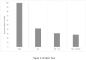
- Figure 2 reports the percentage erosion rate with respect to steel for erosion tests in experimental conditions (Test 2) reported below in order to highlight the behaviour of the coating only for composite coatings from (NiP-SiC; NiP-SiC/B4C) and commercial KEL (KEL), with total thickness of the coating 50 ⁇ m and for carbon steel for comparison:
- NiP-SiC-B4C composite coating shows an erosion resistance slightly higher than the NiP-SiC and it is able to reduce the amount of eroded material with respect to the steel substrate.
- Corrosion resistance has been evaluated through exposure tests in sour environment.
- the behaviour of the coatings (R5, R6, on steel API 5L X60 was compared with reference materials, i.e. bare API 5L X60. Corrosion was evaluated observing the formation of corrosion products after the test on Miller shaped samples.
- Tests in sour environment were performed by contact with salt solutions, hydrogen sulfide 3% and carbon dioxide 13%.
- each sample (Miller metal block 2.5 x 1.3 x 0.5 cm) is washed and sonicated in water, then degreased with aceton, dried in a nitrogen stream and weighed (0.1 mg precision) and placed on the arm in the tray.
- the applied load on standard Miller block samples was 22.24 N. Miller tests and SAR numbers were performed and calculated according to the standard for the coatings and a reference material (Steel Fe-27Cr). For the NiP coatings, a specific weight of 7,75 g/cm 3 was used.
- the low corrosion resistance featured by the steel substrate underline the importance of having an optimal adherence of the coating to the substrate. A detachment caused by accidental reasons would compromise the excellent corrosion resistance performances of the coating.
- NiP / SiC and NiP /SiC / B4C have generally regular morphology.
Description
- This Patent Application claims priority from
Italian Patent Application No. 102019000012972 filed on July 26, 2019 - The invention provides a system comprising a substrate and an electroless composite coating comprising a layered structure alternating a metallic NiP layer and a composite NiP layer. The invention further pertains to the method of preparation of said system and to its uses.
- Solid particle erosion is material removal/damage to a solid surface produced by repeated impacts of solid particles. It is to be expected whenever hard particles are entrained in a gas or liquid medium impinging on a solid at any significant velocity. The solid-liquid erosion is known as slurry erosion. Slurry erosion has become a serious problem for the performance, reliability, and service life of slurry equipment used in many industrial applications such as: mining machinery components, hydraulic transport of solids in pipelines, marine, oil gas and power generation industries.
- Electroless Ni-P coatings have been well known as a hard coating for industrial applications, due to their good corrosion and wear resistance properties. They are usually obtained by co-depositing particulate materials, such as ceramics, diamond and fluoropolymers and carbides of silicon, tungsten and chromium. This valuable process can coat not only electrically conductive materials including graphite but also fabrics, insulators like plastics, rubber etc.
- Examples of electroless Ni-composite plated substrates and methods of preparations thereof are found in
US 2009/0011136 ,US 20111/0162751 US2013/0143031 , andUS2016/0010214 . -
US4358923A discloses processes and articles for composite electroless coatings comprising at least two distinct layers, the first layer comprising a metal and/or a metal alloy plus particulate matter and the second layer comprising a metal and/or a metal alloy and being substantially free of particulate matter. -
US2011226144A1 discloses a doctor blade for wiping printing ink off a surface of a printing plate and/or for use as a paper doctor knife; at least the working edge region of the doctor blade is covered with a coating on the basis of a nickel-phosphorus alloy; in some embodiments, the coating comprises a composite layer of NiP, containing particles of different size and nature, and a metallic layer of NiP. - The major advantages of the electroless Ni-P plating deposition process include the formation of a uniform deposit on irregular surfaces, direct deposition on surface-activated non-conductors, and the formation of non-magnetic, low internal stress deposits. Furthermore, when accompanied by an appropriate post-heat treatment, the wear resistance of the coatings can be improved considerably. The effectiveness of using a composite electroless Ni-P-SiC coating system for cavitation erosion protection of steel has also been observed.
- In the oil and gas field, the main application of the electroless Ni-P coatings is in the increase of wear resistance of parts in choke valves and in the protection of the inner/outer surface of the pipelines.
- Pipelines play an important role throughout the world as a means of transporting gases and liquids over long distances from their source to the supply. According to the environment and to the fluid, abrasion and erosion phenomena can degrade rapidly the wall of the pipeline, losing integrity. Hence, in the oil and gas field, in particular for the coating of the inner surfaces of the pipelines, a very high wear (abrasive/erosive) resistance is required combined with an improved corrosion protection to harsh environment. However, the combination of these two properties is hard to achieve through the traditional and commercially available technology of composite electroless deposition.
- In fact, the existing available processes are mainly intended for applications where wear resistance is needed and the corrosion protection is not a major issue. It is known that composite coatings are not able to offer a very high corrosion protection, typically less than the metal matrix alone.
- Therefore, the need remains to provide an electroless composite with further improved erosion-corrosion resistance.
- The present invention relates to a system comprising a substrate and an electroless composite coating in contact with the substrate as claimed by claim 1.
- Preferably the composite NiP layer comprises P in amounts between 1 and 20 wt%, more preferably in an amount between 7 and 15 wt%.
- Ni and P together with any other metallic element, which may be present in the metallic and/or the composite layer form a so called metallic matrix. The amount of P is defined with respect to the total weight of the metallic matrix.
- Preferably, the particles have average size between 10-5000 nm, more preferably between 50-3000 nm.
- The dispersed particles are a blend comprising first and second particles different in size and nature, preferably the first particles have average size between 100-5000 nm, more preferably between 500-3000 nm and the second particles have average size between 10-2000 nm, more preferably between 50-500 nm.
- Advantageously, the dispersed particles are boron carbide particles and/or silicon carbide nanoparticles.
- Preferably the metallic NiP layer and the composite NiP layer comprise the same amount of P with respect to Ni.
- Preferably the composite NiP layer consists essentially of Ni and P and the dispersed particles or of Ni, P, the dispersed particles and one or more further metallic element.
- Preferably, the metallic NiP layer consists essentially of Ni and P or of Ni, P and one or more further metallic element.
- A layer alternation is defined as any alternation between a metallic and a composite layer or a composite and a metallic layer. Conveniently, the alternation occurs from 2 to 12 times, preferably from 3 to 11 times, more preferably 5, 7 or 9 times. For example, an alternation of metallic/composite/metallic layers or composite/metallic/composite accounts for 2 times (3 layers) or an alternation of composite/metallic/composite/metallic layers for 3 times (4 layers). A coating with more than 12 alternations is still possible however it may become too expensive and time consuming to be produced.
- Preferably, the layered structure consists of 3, 4, 5, 6, 7, 8, 9 or 10 layers, more preferably of 6, 8 or 10, even more preferably of 8 layers.
- According to an embodiment of the invention, the electroless composite coating consists of the layered structure of alternating metallic NiP layers and composite NiP layers.
- Preferably, the layer formed over and in contact with the substrate is a metallic NiP layer and or preferably the outer layer is a composite NiP layer.
- The invention also provides a pipeline as claimed by
claim 10, coated with the electroless composite coating as described above. Preferably the pipeline is coated with the electroless composite coating in its inner surface. - The present invention in addition provides the use of the system of the invention to improve the resistance of a pipeline to chemical and mechanical degradation as claimed by claim 12.
- The present invention further provides a method to produce the system of the invention as claimed by claim 13. Said method comprises the following steps:
- a) Substrate preparation;
- b) Deposition of a metallic NiP layer, or of a composite NiP layer on the substrate,
- c) Deposition of a composite NiP layer on the substrate coated with metallic NiP layer or deposition of a metallic NiP layer on the substrate coated with composite NiP layer; wherein step c) is repeated at least two times (three layers).
- Preferably, the method includes a thermal treatment comprising heating the system after deposition of at least a layer at temperatures in the range 200-600 °C.
- The present invention relates to a system comprising a substrate and an electroless composite coating in contact with the substrate; the electroless composite coating comprising a layered structure alternating a metallic NiP layer, comprising Ni and P and a composite NiP layer comprising Ni, P and particles dispersed therein, wherein the dispersed particles are a blend comprising first and second particles wherein the first and the second particles are different in size and nature.
- Preferably the electroless composite coating consists of a layered structure alternating a metallic NiP layer, comprising Ni and P and a composite NiP layer comprising Ni, P and particles dispersed therein, wherein the dispersed particles are a blend comprising first and second particles wherein the first and the second particles are different in size and nature, and wherein the alternation is repeated 3 to 11 times, preferably 5, 7 or 9 times.
- Preferably the electroless composite coating consists of a layered structure alternating a metallic NiP layer, comprising Ni and P and a composite NiP layer comprising Ni, P and particles dispersed therein, wherein the dispersed particles are a blend comprising first and second particles wherein the first and the second particles are different in size and nature, for a total of 4, 6, 8, 10 layers, preferably, 6, 8, even more preferably 8.
- The invention pertains to an electroless composite coating comprising a layered structure alternating a metallic NiP layer comprising Ni and P; a composite NiP layer comprising Ni, P and dispersed particles; and a further NiP layer or composite NiP layer. Namely, the electroless composite coating comprises or preferably consists of a single or repeated layered structure of metallic NiP/composite NiP/metallic NiP layers or composite NiP/metallic NiP/composite NiP layers.
- The metallic NiP layer is different from the composite NiP layer. Preferably, the metallic NiP layer does not contain any particles dispersed therein.
- Preferably the metallic NiP layer and/or the composite NiP layer comprises P in amounts between 1 and 20 wt%, more preferably in an amount between 7 and 15 wt%.
- Ni and P together with any other metallic element, which may be present in the metallic and/or the composite layer form a so called metallic matrix. The amount of P is defined with respect to the total weight of the metallic matrix.
- The metallic NiP layer comprises, preferably consists of Ni and P. The metallic NiP layer may also contain other suitable metallic elements, e.g. tungsten, cobalt, copper, etc., according to the known art on anticorrosive blends and alloys, in amounts between 0.1 wt%. and 30 wt% with respect to the total weight of the metallic matrix of the metallic NiP layer.
- The composite NiP layer comprises and preferably consists of Ni, P and particles dispersed therein in amounts between 0.1% vol. and 50% vol., preferably between 10 % vol. and 40 % vol., with respect to the total volume of the layer, as measured by image analysis of the cross section of the composite layer.
- The composite NiP layer may also contain other suitable metallic elements, e.g. tungsten, cobalt, copper, etc., in amounts between 0.1% wt. and 30% wt., according to the known art on anticorrosive blends and alloys, in amounts between 0.1 wt%. and 30 wt% with respect to the total weight of the metallic matrix of the composite NiP layer.
- Particle content in the layer is estimated by analysing the images of the sections obtained from optical or SEM microscopy via the "Image J" software.
- Preferably the metallic NiP layer and the composite NiP layer comprise the same amount of Ni and or P.
- Preferably the composite NiP layer comprises and more preferably consists of the metallic matrix of the metallic NiP layer and of the dispersed particles.
- The dispersed particles are a blend comprising first and second particles different in size and nature, and the blend may comprise further particles, which may be different in size and nature from first and second particles or the further particles may be different in nature but have the same size of the first or the second particles. However, the blend of dispersed particles preferably consists of the first and second dispersed particles.
- Particles can be of metallic, ceramic, carbon or polymeric materials. Preferably the particles are ceramic particles, more preferably ceramic particles with a hardness of 8 or higher in the Mohs scale. Examples of suitable ceramic particles are made of zirconia, silicon nitride, tungsten carbide, titanium nitride, silicon carbide, zirconium carbide, alumina, boron carbide, boron nitride, diamond. More preferably the particles are boron carbide and/or silicon carbide nano- and micro-particles.
- Preferably the dispersed particles have an average size between 10 and 5000 nm.
- Preferably the first particles have an average size between 200 and 5000 nm and more preferably between 500 and 3000 nm.
- Preferably the second particles have an average size between 10 and 2000 nm, more preferably between 50 and 500 nm.
- Preferably the first particles have size larger than the second particles. More preferably, first and second particles have a difference in average sizes of at least 100 nm, more preferably in the range 300-1500 nm.
- More preferably the first particles are boron carbide particles and have average size between 500-3000 nm and the second particles are silicon carbide nanoparticles and have average size between 50 and 500 nm.
- The average size of the particles is measured according to the standard ISO 9276-2:2001.
- Preferably the first particles are dispersed in the composite layer matrix in amounts between 10% vol. and 40% vol. with respect to total volume of the composite layer, more preferably between 10% vol. and 30% vol.
- Preferably the second particles are dispersed in the composite layer matrix in amounts between 0.1% vol. and 30% vol. more preferably between 1% vol. and 20% vol. with respect to the total volume of the composite layer.
- Preferably the volume ratio between the first and second particles dispersed in the matrix is comprised within the range from 0.8 to 50, more preferably from 1 to 10.
- The thickness of the multilayer composite coating may range from 1 to 150 µm, preferably it is in the range 50-80 µm. Preferably, the metallic NiP and composite NiP layer has a thickness in the range of 500 nm - 100 µm, more preferably in the range of 1 to 50 µm. The metallic and the composite layers may have different thickness from one another.
- Conveniently, the alternation is applied from 2 to 11 times, preferably 5, 7 or 9 times.
- Preferably, the layered structure consists of 3, 4, 5, 6, 7, 8, 9 or 10 layers, more preferably of 6, 8 or 10 layers, even more preferably of 8 layers.
- The multilayered composite coatings can be thermally treated after deposition to improve their mechanical properties, such as hardness. Thermal treatment can be applied for 1 to 8 hours in the range 250 - 550 °C. Programmed heating profiles may be applied, according to known methods in the art.
- Preferably, the layer formed over and in contact with the substrate is a metallic NiP layer and or preferably the outer layer is a composite NiP layer.
- The substrate can include metals and their alloys, carbon and ceramic materials, and polymeric ones. Preferably the substrate is metallic or is plate plated with a metallic layer for subsequent electroless nickel plating thereon. The substrate may be selected from steel, brass, aluminium, aluminium alloy, copper, titanium, titanium alloy, iron, nickel, nickel alloy, bronze, stainless steel or combination thereof. The substrate is preferably steel.
- According to a preferred configuration, the first layer facing the substrate is a metallic NiP layer, while the outer one is a composite NiP layer.
- The invention also provides a pipeline coated with the electroless composite coatings described above. Preferably the pipeline is coated with the electroless composite coating of the invention in its inner surface.
- The invention further provides a method to produce the system of the invention comprising the electroless composite coating described above. Said method comprises the following steps:
- a) Substrate preparation, which preferably comprises cleaning the substrate surface e.g. from organic residues and oxides. Preferably standard degreasing and etching solutions are used.
- b) Deposition of a metallic NiP layer, or of a composite NiP layer on the substrate, said deposition preferably comprising contacting, preferably by immersion, the substrate with a NiP based solution to deposit the metallic NiP layer, or with a NiP based solution containing particles to deposit the composite NiP layer;
- c) Deposition of a composite NiP layer on the substrate coated with metallic NiP layer or deposition of a metallic NiP layer on the substrate coated with composite NiP layer, said deposition preferably comprising contacting, preferably by immersion, the coated substrate with a NiP based solutions to deposit the metallic NiP layer or, respectively, with a NiP based solutions containing particles to deposit the composite NiP layer;
- Step c) may be repeated as many time as necessary as long as the alternation metallic NiP layer/composite NiP layer or composite NiP layer/ metallic NiP layer is maintained. Step c) is repeated from 2 to 10 times, more preferably from 5 to 9 times.
- According to an embodiment of the present invention, any or each step b) or c) of the method to produce the electroless coated system may be carried out by more than one coating phase in sequence, possibly in more than one batch. Coating steps carried out in multiple phases may be needed, e.g., for obtaining a thicker layer, e.g. 3000 nm.
- Optionally, step a) of the method includes substrate activation, following substrate preparation. The activation may be achieved by palladium activation, electrochemical activation or by contact with less noble materials.
- Preferably a washing step with water or an aqueous liquid is carried out at the end of step b) or each step c).
- Optionally, the method includes a thermal treatment heating the system after deposition of at least a layer, preferably after all the layer have been deposited. The thermal treatment improves the mechanical properties of the system and of the electroless coating. Thermal treatment is preferably carried out at temperatures in the range 200-600 °C, more preferably in the range 250-550 °C.
- NiP based solutions for electroless plating, suitable for carrying out either step b) or step c), are well known in the art and may be commercially available. They normally comprise compositions of at least a soluble Ni salt, e.g. a sulphate, and at least an ipophosphite salt. Several other components such as inhibitors, hydrogen absorbers, buffer systems, catalysts or other metal salts may be present.
- Examples of electroless plating are described in "Glenn O. Mallory, Juan B. Hajdu, Electroless Plating: Fundamentals and Applications, AESF 1990".
- In step b) or c), suitable particles in a convenient amount are suspended in the NiP solution, in order to achieve the desired amount of particles mixed with the NiP matrix in the composite layer. Preferred concentration of particles in the suspensions are in the range 1 - 10 g/L. Surfactants may also be present in order to stabilize the suspension. Suspended particles in step b) or c) have size and distribution according to the size and distribution of particles in the composite NIP layer of the desired coating of the present invention and are preferably SiC particles with an average size from 50 to 500 nm or B4C particles with an average size from 500 to 3000 nm.
- Steps b) and c) are preferably carried out at a temperature from 55°C to 98 °C, more preferably from 70 to 95 °C. Preferred deposition time of each step is comprised from 1 min. to 60 min., more preferably from 5 min. to 20 min.. Different thickness of each layer may be obtained by varying time and temperature of the electroless plating step.
- According to a preferred embodiment, step b) is a deposition of a metallic NiP layer and step c) is first carried out as a deposition of a composite NiP layer and then repeated an even number of times, preferably 4, 6 or 8 times, maintaining alternation of metallic and composite layer deposition, in order to obtain a composite outer layer.
- The invention further provides a pipeline coated with the electroless composite coating described above. Preferably the pipeline is coated in its inner surface.
- The invention further pertains to the use of system comprising the electroless composite coating described above for increasing corrosion resistance of pipelines.
-
-
Figure 1 shows a SEM image of sample R6 (NiP / SiC / B4C); -
Figure 2 shows the eroded mass as percentage variation with respect to steel in erosion test for coatings. - Samples as described on table 1 were prepared. All samples R1-R6 have an alternating multilayer of metallic NiP layer and composite NiP layer structure. In R1, R3 and R5, the composite NiP layers contain a single type of dispersed particles. Samples R2, R4 and R6 contain a blend of first and second dispersed particles. KEL is a commercial coating, which consists of a layer of 30 µm NiP with on top a layer of 20 µm NiP/SiC with submicron SiC particles.
- The total amount of co-deposited particles in the composite NiP layer is about 25% vol. (evaluated by image analysis of the cross section of the composite layer) with P content in both the metallic and composite layers of 10% wt.
Table 1 Sample name Coating's material Notes R1 NiP+NiP/SiC on bare unpolished X60 steel with Pd activation Thermally treated 1 h at 400°C R2 NiP+NiP/SiC/B4C on bare unpolished X60 steel with Pd activation R3 NiP+NiP/SiC on lapped X60 R4 NiP+NiP/SiC/B4C on lapped X60 R5 NiP+NiP/SiC Thermally treated 1 h at 400°C R6 NiP+NiP/SiC/B4C Thermally treated 1 h at 400°C KEL Commercial coating (NiP+NiP/SiC) Thermally treated 1 h at 400°C X60 Carbon steel API 5L X60 Substrate - The results presented are based on the use of Tecnoplate 3000® commercial formulation (provided by Tecnochimica SpA) with addition of SiC nanoparticles having an
average size 100 nm and B4C submicron particles having an average size 800-1000 nm, with the following concentration in the bath 2 g/l and 4 g/l, respectively, when a first and second particle type is used. - Typical deposition parameters are:
- pH = 4.8 and T = 90 °C;
- Deposition total time = 2-4 hours;
- Thickness of the entire structure for all the samples = 50 µm
- Particles total concentration in the bath = 6 g/l
- Post thermal treatment = 400 °C for 1 hour
- Steel substrate was sonicated in acetone for 10 minutes, rinsed thoroughly, etched in sulphuric acid concentrated at 20% for 5 minutes and rinsed again. Tecnoplate 3000® was formulated according to the Tecnochimica guidelines; for composite plating, the selected amount of powders was added to the above cited solution and the batch was sonicated for 15-20 minutes. Activated steel was then immersed for 15 minutes in metallic plating solution at 85°C to deposit a seed layer of NiP alloy. NiP plated substrate was then rinsed with water and immersed in the composite plating bath with Silicon Carbide or a mixture of Silicon Carbide and Boron Carbide for 2 hours at 85-90°C; the composite layer was then plated with NiP by immersing the sample in the metallic Tecnoplate solution for 10 minutes at 85°C. Composite plating and NiP plating steps have been repeated alternatively so as to obtain the final coating with 8 alternating layers (except sample KEL), the outer surface thereof being a composite layer.
- At the end of the treatment, samples appeared dull and dusky; surface smoothing with abrasive paper was indeed carried out to obtain a polished surface. Final thermal heating, when applied, was carried out by holding the coated plates at 400°C in air for 1 hour as thermal treatment.
- The samples were characterized according to the following procedures:
-
Figure 1 shows a Scanning Electron Microscope (SEM) image of sample R6 (NiP / SiC / B4C). - Morphological characterization of composite coatings shows the typical features of composite materials. Surface appearance, if not lapped, is dull and matt, while cross section observations show a two phases structure constituted by the NiP alloy metal matrix and the dispersion phase, i.e. SiC or mixture of SiC and B4C. A multilayer structure due to NiP and composite layer alternation is also observed. The NiP matrix is obtained in a high phosphorus plating electrolyte with P content in the matrix typically, 10% by weight.
- The crystalline structure evolution (XRD) with thermal treatment at various temperature between 300-500 °C for 1 hour shows the initial amorphous structure evolves into a crystalline one constituted by metallic Ni and hard NixPy intermetallic compounds.
- Table 2 reports the results of the micro-hardness measurements performed on sections of the samples described above. The thickness of the coatings (ranging from 50-200 µm) and the morphology of the coatings has required the use of micro-indentation (100 g weight).
- Table 2 also reports the results `Surface texture' (Sa) measurements obtained by optical digital microscopy.
- Erosion tests have been performed in an experimental station composed of a mixing tank, a centrifugal pump and a test tank containing the nozzle and the sample, using a slurry prepared by mixing water and sand. Commercial sand was used, named "Impalpabile" from Sabbie Sataf (size < 400 µm).
- The nozzle is made of tungsten carbide with a cylindrical shape and an internal diameter of 8 mm.
- Previously weighed samples (6.9 x 7.5 x 0.4 cm) were subjected to a slurry highpressure perpendicular jet from the nozzle, for a variable duration time comprised between 2 and 5 minutes. The slurry is continuously circulated from the mixing tank through the centrifugal pump to the nozzle in the test tank and then back to the mixing tank. The nozzle is placed within the test tank at a distance of 20 mm from the surface of the sample to be tested, with the jet directed perpendicularly to the surface. Both the nozzle and the sample are completely sunk in the slurry so that no gas is entrained by the jet. After the test, each sample is washed, rinsed and weighed again.
- The erosion factor has been calculated as ER = ΔM/ρsQCT, wherein:
- ΔM
- Mass lost from the sample during the test
- T
- Test time
- ρs
- Density of solids in the mixture
- Q
- Flow rate
- C
- volumetric concentration of solids in the mixture
- v
- Jet speed
- ER
- Erosion Ratio
- For each material the average ER is calculated from ER measured on samples tested at 2, 3 and 5 minutes duration time respectively.
-
Figure 2 reports the percentage erosion rate with respect to steel for erosion tests in experimental conditions (Test 2) reported below in order to highlight the behaviour of the coating only for composite coatings from (NiP-SiC; NiP-SiC/B4C) and commercial KEL (KEL), with total thickness of the coating 50 µm and for carbon steel for comparison: - Test 2 conditions were:

- Distance sample - nozzle: 20 mm


- These operating conditions lead to the erosion of the coating alone, with minor contribution from the substrate.
- If the behaviour of the coatings only is emphasized, NiP-SiC-B4C composite coating shows an erosion resistance slightly higher than the NiP-SiC and it is able to reduce the amount of eroded material with respect to the steel substrate.
- Corrosion resistance has been evaluated through exposure tests in sour environment. The behaviour of the coatings (R5, R6, on steel API 5L X60 was compared with reference materials, i.e. bare API 5L X60. Corrosion was evaluated observing the formation of corrosion products after the test on Miller shaped samples.
- Tests in sour environment were performed by contact with salt solutions, hydrogen sulfide 3% and carbon dioxide 13%.
- In a pressurized chamber in Hastelloy C276 (volume 1 liter), previously weighed samples (Miller Test blocks, 2.5 x 1.3 x 0.5 cm) were immersed in 300 mL water solution containing 30 g/l of chlorides as NaCl. After closing the pressurized chamber, a gas mixture containing (by vol.): H2S 3%, CO2 13%, N2 85% was charged under heating until the following conditions were reached:
- temperature 90 °C
-
pressure 100 bar - The samples were maintained under these conditions for a duration of 7 days.
- For the bare steel X60 the test lasted only 24 hours due to the fast degradation of the materials. At the end of each test, weight losses have been evaluated and summarized in the following table 2.
- Miller tests have been performed in a Miller Machine with four plastic trays, according to ASTM G75 (Standard), using a slurry prepared by mixing water and sand in the ratio 1/1. Commercial sand was used, named "Impalpabile" from Sabbie Sataf (size < 400 µm). The MN number of this slurry with the reference material (steel Fe-27Cr) is 156. The bottom of each tray in the machine was covered with a rubber lap of neoprene (Modified MIL-R-855C, Class 2, Grade 80). Before test, each sample (Miller metal block 2.5 x 1.3 x 0.5 cm) is washed and sonicated in water, then degreased with aceton, dried in a nitrogen stream and weighed (0.1 mg precision) and placed on the arm in the tray.
- The applied load on standard Miller block samples was 22.24 N. Miller tests and SAR numbers were performed and calculated according to the standard for the coatings and a reference material (Steel Fe-27Cr). For the NiP coatings, a specific weight of 7,75 g/cm3 was used.
- In order to most appropriately apply the Miller test to coated samples, suitable conditions were selected whereby erosion was essentially limited to the coating layer, without abrading the less resistant below carbon steel. Therefore, the Mille Number was calculated as the tangent slope of the interpolation at 40 minutes instead of two hours as requested by the standard procedure. It was checked that ins such conditions, less than 30 % of the surface of each sample showed exposed metal substrate. In this way, only the abrasion resistance of the coating was measured. Miller test was also performed on two samples of examples R5 and R6 previously submitted to the corrosion test (examples R5C and R6C respectively.
- Characterization results are reported on Table 2.
Table 2 R1 R2 R3 R4 R5 R6 R5C R6C X60 KEL Average Microhardness (12 meas.) 820 750 150 Average Roughness 2.2 2.2 Average velocity of corrosion (2 meas.) (mm/y) < 0.002 < 0.002 1.9 Miller test (Slope at 40 min.) 1109 724 853 718 1326 1254 1099 904 3986 1689 - On the basis of the acquired data, it can be concluded that all the tested coatings have a better abrasion resistance than steel X60 (used as substrate).
- The corrosion treatment (samples R5C and R6C) does not decrease the abrasion resistance of the coatings. On the contrary, a surprising improvement was seen. According to the SAR results (t = 40 minutes for samples with abrasion of the coating lower than 30%) the best coatings appear to be NiP/SiC/B4C (R2, R4, R6 and R6C); the last two positions are for of commercial coating KEL and the substrate (X60).
- As far as the corrosion test is concerned, all the coatings of the invention show an excellent corrosion resistance. The corrosion velocity is always well below 0,1 mm/year (which defines the suitability of the metallic material used in the sector Oil&Gas). This is a particularly lower value considering the thickness of the coatings (between 50-200 µm). It can be assumed that in aggressive conditions ('sour') the coating could withstand even longer period. It shall also be noted that the corrosion resistance of this sample is superior than the one of WC, widely used for Oil & Gas applications.
- The low corrosion resistance featured by the steel substrate underline the importance of having an optimal adherence of the coating to the substrate. A detachment caused by accidental reasons would compromise the excellent corrosion resistance performances of the coating.
- Morphology studies done by SEM have demonstrated that NiP / SiC and NiP /SiC / B4C have generally regular morphology.
Claims (14)
- A system comprising a substrate and an electroless composite coating in contact with the substrate, wherein the electroless composite coating comprising a layered structure alternating a metallic NiP layer comprising Ni and P and a composite NiP layer, said composite NiP layer comprising Ni, P and dispersed particles, wherein the dispersed particles are a blend comprising first and second particles and the first and the second particles are different in size and nature, and wherein the layered structure alternating at least a metallic NiP layer comprising Ni and P; at least a composite NiP layer comprising Ni, P and dispersed particles; and at least a further NiP layer or composite NiP layer.
- The system according to claim 1 wherein the metallic NiP layer and/or the composite NiP layer comprises P in an amount between 1 and 20 wt% with respect to the total weight of the metallic matrix in the layer.
- The system according to claim 1 or 2 wherein the first particles have average size between 500-3000 nm and the second particles have average size between 50-500 nm.
- The system according to any one of the preceding claims wherein the particles are boron carbide particles and/or silicon nanoparticles.
- The system according to anyone of the preceding claims wherein the metallic NiP layer consists of Ni and P or of Ni, P and one or more further metallic element.
- The system according to anyone of the preceding claims wherein the composite NiP layer consists of Ni and P and the blend of dispersed particles, or of Ni, P, the blend of dispersed particles and one or more further metallic element.
- The system according to any one of the preceding claims, wherein the alternation occurs from 3 to 11 times, preferably 5, 7 or 9 times.
- The system according to any one of the preceding claims, wherein the layer formed over and in contact with the substrate is a metallic NiP layer.
- The system according to any one of the preceding claims, wherein the outer layer is a composite NiP layer.
- A pipeline comprising the system according to any one of claims 1 to 9.
- The pipeline according to claim 10, which is coated in its inner surface.
- Use of the system as claimed in any one of claims 1 to 9 to improve the resistance of a pipeline to chemical and mechanical degradation.
- A method to produce the system of any one of claims 1 to 9 or the pipeline as claimed in claim 10 or 11, comprising the following steps:a) Substrate preparation;b) Deposition of a metallic NiP layer, or of a composite NiP layer on the substrate,c) Deposition of a composite NiP layer on the substrate coated with metallic NiP layer or deposition of a metallic NiP layer on the substrate coated with composite NiP layer;wherein the step c) is repeated at least two times (three layers),optionally the method further comprising a thermal treatment comprising heating the system after deposition of at least a layer at temperatures in the range 200-600 °C.
- The method according to claim 13, wherein step c) is repeated as many time as necessary as long as the alternation metallic NiP layer/composite NiP layer or composite NiP layer/ metallic NiP layer is maintained, preferably is repeated up to 10 times.
Applications Claiming Priority (2)
| Application Number | Priority Date | Filing Date | Title |
|---|---|---|---|
| IT201900012972 | 2019-07-26 | ||
| PCT/IB2020/057025 WO2021019406A1 (en) | 2019-07-26 | 2020-07-24 | Multilayered nickel-phosphorus composite |
Publications (2)
| Publication Number | Publication Date |
|---|---|
| EP4004256A1 EP4004256A1 (en) | 2022-06-01 |
| EP4004256B1 true EP4004256B1 (en) | 2024-01-17 |
Family
ID=68653533
Family Applications (1)
| Application Number | Title | Priority Date | Filing Date |
|---|---|---|---|
| EP20747144.2A Active EP4004256B1 (en) | 2019-07-26 | 2020-07-24 | Multilayered nickel-phosphorus composite |
Country Status (4)
| Country | Link |
|---|---|
| US (1) | US20220259742A1 (en) |
| EP (1) | EP4004256B1 (en) |
| DK (1) | DK4004256T3 (en) |
| WO (1) | WO2021019406A1 (en) |
Family Cites Families (7)
| Publication number | Priority date | Publication date | Assignee | Title |
|---|---|---|---|---|
| US4358923A (en) * | 1980-04-10 | 1982-11-16 | Surface Technology, Inc. | Composite coatings for open-end machinery parts |
| US20090011136A1 (en) | 2005-05-06 | 2009-01-08 | Thomas Steven Lancsek | Composite electroless plating |
| JP4495054B2 (en) * | 2005-09-02 | 2010-06-30 | 三菱重工業株式会社 | Rotary machine parts and rotary machines |
| CH699702A1 (en) * | 2008-10-07 | 2010-04-15 | Daetwyler Swisstec Ag | Diamond-coated blade. |
| IT1397144B1 (en) | 2009-11-30 | 2013-01-04 | Nuovo Pignone Spa | PLATED SUBSTRATE NOT ELECTRICALLY COMPOSED OF NICKEL AND METHOD. |
| US20110162751A1 (en) | 2009-12-23 | 2011-07-07 | Exxonmobil Research And Engineering Company | Protective Coatings for Petrochemical and Chemical Industry Equipment and Devices |
| US20160010214A1 (en) | 2014-07-10 | 2016-01-14 | Macdermid Acumen, Inc. | Composite Electroless Nickel Plating |
-
2020
- 2020-07-24 DK DK20747144.2T patent/DK4004256T3/en active
- 2020-07-24 US US17/630,011 patent/US20220259742A1/en active Pending
- 2020-07-24 EP EP20747144.2A patent/EP4004256B1/en active Active
- 2020-07-24 WO PCT/IB2020/057025 patent/WO2021019406A1/en unknown
Also Published As
| Publication number | Publication date |
|---|---|
| EP4004256A1 (en) | 2022-06-01 |
| DK4004256T3 (en) | 2024-02-26 |
| US20220259742A1 (en) | 2022-08-18 |
| WO2021019406A1 (en) | 2021-02-04 |
Similar Documents
| Publication | Publication Date | Title |
|---|---|---|
| El Rayes et al. | Erosion-corrosion of cermet coating | |
| TWI674332B (en) | Plating or coating method for producing metal-ceramic coating on a substrate | |
| Zhang et al. | A novel functionally graded Ni-graphene coating and its corrosion resistance | |
| Luo et al. | Synthesis of a duplex Ni-P-YSZ/Ni-P nanocomposite coating and investigation of its performance | |
| EP2374916A1 (en) | Erosion and corrosion resistant coating system for compressor | |
| Xu et al. | Erosion–corrosion behavior of nano-particle-reinforced Ni matrix composite alloying layer by duplex surface treatment in aqueous slurry environment | |
| Gadhari et al. | Electroless nickel-phosphorus composite coatings: A review | |
| Yang et al. | Microstructure and corrosion behavior of electroless Ni–P on sprayed Al–Ce coating of 3003 aluminum alloy | |
| Nezhad et al. | Erosion-corrosion of electrodeposited superhydrophobic Ni-Al2O3 nanocomposite coatings under jet saline-sand slurry impingement | |
| Song et al. | Corrosion resistance of super-hydrophobic coating on AZ31B Mg alloy | |
| Murugesan et al. | Extending the lifetime of oil and gas equipment with corrosion and erosion-resistant Ni-B-nanodiamond metal-matrix-nanocomposite coatings | |
| CN102713003B (en) | Electroless Ni-composite plated substrate and method | |
| Fayomi et al. | Structural and properties of Zn-Al 2 O 3-SiC nano-composite coatings by direct electrolytic process | |
| Julka et al. | Effect of pH on mechanical, physical and tribological properties of electroless Ni-P-Al 2 O 3 composite deposits for marine applications | |
| Shi et al. | Preparation of electroplated Ni-P-ultrafine diamond, Ni-P-carbon nanotubes composite coatings and their corrosion properties | |
| EP4004256B1 (en) | Multilayered nickel-phosphorus composite | |
| Srinivasan et al. | Studies on electroless nickel–PTFE composite coatings | |
| Mindivan et al. | The study of electroless Ni-P/Ni-B duplex coating on HVOF-sprayed martensitic stainless steel coating | |
| Zhang et al. | Electrodeposition of multi-layer Pd–Ni coatings on 316L stainless steel and their corrosion resistance in hot sulfuric acid solution | |
| Fayyaz et al. | Probing into the properties of B4C reinforced nickel phosphorus-based nanocomposite coating | |
| Farhan et al. | Mechanical and corrosion characteristics of TiC reinforced Ni-P based nanocomposite coatings | |
| Zhang et al. | Study of the Corrosion Resistance of a Superhydrophobic Ni-P-Al2O3 Composite Coating Based on Electrochemical Machining | |
| Rabani et al. | Corrosion Behaviour of High Velocity Oxygen Fuel Spray Process and Electrodeposited Coating in Aqueous Environment | |
| Fayomi et al. | Wear stress mitigation and structural characteristics of highly performing zinc-based induced ZrO 2/ZrN composite alloy coating on mild steel | |
| Ma et al. | Electrochemical Characterization of a Nickel-Phosphorus Coating on Diamond Grits |
Legal Events
| Date | Code | Title | Description |
|---|---|---|---|
| STAA | Information on the status of an ep patent application or granted ep patent |
Free format text: STATUS: UNKNOWN |
|
| STAA | Information on the status of an ep patent application or granted ep patent |
Free format text: STATUS: THE INTERNATIONAL PUBLICATION HAS BEEN MADE |
|
| PUAI | Public reference made under article 153(3) epc to a published international application that has entered the european phase |
Free format text: ORIGINAL CODE: 0009012 |
|
| STAA | Information on the status of an ep patent application or granted ep patent |
Free format text: STATUS: REQUEST FOR EXAMINATION WAS MADE |
|
| 17P | Request for examination filed |
Effective date: 20220202 |
|
| AK | Designated contracting states |
Kind code of ref document: A1 Designated state(s): AL AT BE BG CH CY CZ DE DK EE ES FI FR GB GR HR HU IE IS IT LI LT LU LV MC MK MT NL NO PL PT RO RS SE SI SK SM TR |
|
| DAV | Request for validation of the european patent (deleted) | ||
| DAX | Request for extension of the european patent (deleted) | ||
| STAA | Information on the status of an ep patent application or granted ep patent |
Free format text: STATUS: EXAMINATION IS IN PROGRESS |
|
| 17Q | First examination report despatched |
Effective date: 20230221 |
|
| GRAP | Despatch of communication of intention to grant a patent |
Free format text: ORIGINAL CODE: EPIDOSNIGR1 |
|
| STAA | Information on the status of an ep patent application or granted ep patent |
Free format text: STATUS: GRANT OF PATENT IS INTENDED |
|
| INTG | Intention to grant announced |
Effective date: 20230816 |
|
| GRAS | Grant fee paid |
Free format text: ORIGINAL CODE: EPIDOSNIGR3 |
|
| GRAA | (expected) grant |
Free format text: ORIGINAL CODE: 0009210 |
|
| STAA | Information on the status of an ep patent application or granted ep patent |
Free format text: STATUS: THE PATENT HAS BEEN GRANTED |
|
| P01 | Opt-out of the competence of the unified patent court (upc) registered |
Effective date: 20231206 |
|
| AK | Designated contracting states |
Kind code of ref document: B1 Designated state(s): AL AT BE BG CH CY CZ DE DK EE ES FI FR GB GR HR HU IE IS IT LI LT LU LV MC MK MT NL NO PL PT RO RS SE SI SK SM TR |
|
| REG | Reference to a national code |
Ref country code: GB Ref legal event code: FG4D |
|
| REG | Reference to a national code |
Ref country code: DE Ref legal event code: R096 Ref document number: 602020024525 Country of ref document: DE |
|
| REG | Reference to a national code |
Ref country code: CH Ref legal event code: EP |
|
| REG | Reference to a national code |
Ref country code: IE Ref legal event code: FG4D |
|
| REG | Reference to a national code |
Ref country code: DK Ref legal event code: T3 Effective date: 20240221 |