EP4004144B1 - Narrow green-emitting phosphors - Google Patents
Narrow green-emitting phosphors Download PDFInfo
- Publication number
- EP4004144B1 EP4004144B1 EP20753639.2A EP20753639A EP4004144B1 EP 4004144 B1 EP4004144 B1 EP 4004144B1 EP 20753639 A EP20753639 A EP 20753639A EP 4004144 B1 EP4004144 B1 EP 4004144B1
- Authority
- EP
- European Patent Office
- Prior art keywords
- phosphor
- reaction mixture
- heating
- source
- light
- Prior art date
- Legal status (The legal status is an assumption and is not a legal conclusion. Google has not performed a legal analysis and makes no representation as to the accuracy of the status listed.)
- Active
Links
- OAICVXFJPJFONN-UHFFFAOYSA-N Phosphorus Chemical compound [P] OAICVXFJPJFONN-UHFFFAOYSA-N 0.000 claims description 68
- 239000011541 reaction mixture Substances 0.000 claims description 50
- 238000000034 method Methods 0.000 claims description 43
- 238000010438 heat treatment Methods 0.000 claims description 37
- 230000005284 excitation Effects 0.000 claims description 20
- 239000011734 sodium Substances 0.000 claims description 18
- 239000007858 starting material Substances 0.000 claims description 18
- 229910052783 alkali metal Inorganic materials 0.000 claims description 16
- 150000001340 alkali metals Chemical class 0.000 claims description 15
- UIIMBOGNXHQVGW-UHFFFAOYSA-M Sodium bicarbonate Chemical compound [Na+].OC([O-])=O UIIMBOGNXHQVGW-UHFFFAOYSA-M 0.000 claims description 14
- 230000005855 radiation Effects 0.000 claims description 14
- 238000002156 mixing Methods 0.000 claims description 13
- XKRFYHLGVUSROY-UHFFFAOYSA-N Argon Chemical compound [Ar] XKRFYHLGVUSROY-UHFFFAOYSA-N 0.000 claims description 10
- FKNQFGJONOIPTF-UHFFFAOYSA-N Sodium cation Chemical compound [Na+] FKNQFGJONOIPTF-UHFFFAOYSA-N 0.000 claims description 10
- AYJRCSIUFZENHW-UHFFFAOYSA-L barium carbonate Chemical compound [Ba+2].[O-]C([O-])=O AYJRCSIUFZENHW-UHFFFAOYSA-L 0.000 claims description 10
- 238000000295 emission spectrum Methods 0.000 claims description 10
- 230000000284 resting effect Effects 0.000 claims description 10
- ZOXJGFHDIHLPTG-UHFFFAOYSA-N Boron Chemical compound [B] ZOXJGFHDIHLPTG-UHFFFAOYSA-N 0.000 claims description 7
- KGBXLFKZBHKPEV-UHFFFAOYSA-N boric acid Chemical group OB(O)O KGBXLFKZBHKPEV-UHFFFAOYSA-N 0.000 claims description 7
- 229910052796 boron Inorganic materials 0.000 claims description 7
- 229910000030 sodium bicarbonate Inorganic materials 0.000 claims description 7
- 229910052693 Europium Inorganic materials 0.000 claims description 6
- DGAQECJNVWCQMB-PUAWFVPOSA-M Ilexoside XXIX Chemical compound C[C@@H]1CC[C@@]2(CC[C@@]3(C(=CC[C@H]4[C@]3(CC[C@@H]5[C@@]4(CC[C@@H](C5(C)C)OS(=O)(=O)[O-])C)C)[C@@H]2[C@]1(C)O)C)C(=O)O[C@H]6[C@@H]([C@H]([C@@H]([C@H](O6)CO)O)O)O.[Na+] DGAQECJNVWCQMB-PUAWFVPOSA-M 0.000 claims description 6
- 229910052788 barium Inorganic materials 0.000 claims description 6
- DSAJWYNOEDNPEQ-UHFFFAOYSA-N barium atom Chemical compound [Ba] DSAJWYNOEDNPEQ-UHFFFAOYSA-N 0.000 claims description 6
- OGPBJKLSAFTDLK-UHFFFAOYSA-N europium atom Chemical compound [Eu] OGPBJKLSAFTDLK-UHFFFAOYSA-N 0.000 claims description 6
- RSEIMSPAXMNYFJ-UHFFFAOYSA-N europium(iii) oxide Chemical compound O=[Eu]O[Eu]=O RSEIMSPAXMNYFJ-UHFFFAOYSA-N 0.000 claims description 6
- 239000007789 gas Substances 0.000 claims description 6
- 238000004519 manufacturing process Methods 0.000 claims description 6
- 229910052708 sodium Inorganic materials 0.000 claims description 6
- -1 NaHCO3 Chemical class 0.000 claims description 5
- 229910052786 argon Inorganic materials 0.000 claims description 5
- 239000003085 diluting agent Substances 0.000 claims description 4
- 238000000695 excitation spectrum Methods 0.000 claims description 4
- 229910052724 xenon Inorganic materials 0.000 claims description 4
- FHNFHKCVQCLJFQ-UHFFFAOYSA-N xenon atom Chemical compound [Xe] FHNFHKCVQCLJFQ-UHFFFAOYSA-N 0.000 claims description 4
- 159000000009 barium salts Chemical class 0.000 claims description 3
- 239000001307 helium Substances 0.000 claims description 3
- 229910052734 helium Inorganic materials 0.000 claims description 3
- SWQJXJOGLNCZEY-UHFFFAOYSA-N helium atom Chemical compound [He] SWQJXJOGLNCZEY-UHFFFAOYSA-N 0.000 claims description 3
- 230000001678 irradiating effect Effects 0.000 claims description 3
- 229910052743 krypton Inorganic materials 0.000 claims description 3
- DNNSSWSSYDEUBZ-UHFFFAOYSA-N krypton atom Chemical compound [Kr] DNNSSWSSYDEUBZ-UHFFFAOYSA-N 0.000 claims description 3
- 229910052754 neon Inorganic materials 0.000 claims description 3
- GKAOGPIIYCISHV-UHFFFAOYSA-N neon atom Chemical compound [Ne] GKAOGPIIYCISHV-UHFFFAOYSA-N 0.000 claims description 3
- 159000000000 sodium salts Chemical class 0.000 claims description 3
- 239000004065 semiconductor Substances 0.000 claims description 2
- 150000000918 Europium Chemical class 0.000 claims 1
- 229910003564 SiAlON Inorganic materials 0.000 description 13
- 229910052909 inorganic silicate Inorganic materials 0.000 description 12
- 238000006243 chemical reaction Methods 0.000 description 11
- 150000001875 compounds Chemical class 0.000 description 10
- 238000005424 photoluminescence Methods 0.000 description 10
- 238000001228 spectrum Methods 0.000 description 10
- OKTJSMMVPCPJKN-UHFFFAOYSA-N Carbon Chemical compound [C] OKTJSMMVPCPJKN-UHFFFAOYSA-N 0.000 description 8
- 239000000203 mixture Substances 0.000 description 8
- 229910001415 sodium ion Inorganic materials 0.000 description 8
- 229910020440 K2SiF6 Inorganic materials 0.000 description 7
- 125000004429 atom Chemical group 0.000 description 7
- 230000015572 biosynthetic process Effects 0.000 description 7
- 238000006862 quantum yield reaction Methods 0.000 description 7
- 238000003786 synthesis reaction Methods 0.000 description 7
- 239000003086 colorant Substances 0.000 description 6
- 230000003287 optical effect Effects 0.000 description 6
- 230000007423 decrease Effects 0.000 description 5
- 238000009877 rendering Methods 0.000 description 5
- XDFCIPNJCBUZJN-UHFFFAOYSA-N barium(2+) Chemical compound [Ba+2] XDFCIPNJCBUZJN-UHFFFAOYSA-N 0.000 description 4
- 230000008901 benefit Effects 0.000 description 4
- 229910052799 carbon Inorganic materials 0.000 description 4
- 239000000463 material Substances 0.000 description 4
- 239000000843 powder Substances 0.000 description 4
- QGZKDVFQNNGYKY-UHFFFAOYSA-N Ammonia Chemical compound N QGZKDVFQNNGYKY-UHFFFAOYSA-N 0.000 description 3
- UGFAIRIUMAVXCW-UHFFFAOYSA-N Carbon monoxide Chemical compound [O+]#[C-] UGFAIRIUMAVXCW-UHFFFAOYSA-N 0.000 description 3
- 238000002441 X-ray diffraction Methods 0.000 description 3
- 229910002091 carbon monoxide Inorganic materials 0.000 description 3
- 238000012512 characterization method Methods 0.000 description 3
- 239000013078 crystal Substances 0.000 description 3
- 238000004020 luminiscence type Methods 0.000 description 3
- 238000005259 measurement Methods 0.000 description 3
- 229920000642 polymer Polymers 0.000 description 3
- VYPSYNLAJGMNEJ-UHFFFAOYSA-N silicon dioxide Inorganic materials O=[Si]=O VYPSYNLAJGMNEJ-UHFFFAOYSA-N 0.000 description 3
- 230000005469 synchrotron radiation Effects 0.000 description 3
- IJGRMHOSHXDMSA-UHFFFAOYSA-N Atomic nitrogen Chemical compound N#N IJGRMHOSHXDMSA-UHFFFAOYSA-N 0.000 description 2
- 229920000742 Cotton Polymers 0.000 description 2
- LFQSCWFLJHTTHZ-UHFFFAOYSA-N Ethanol Chemical compound CCO LFQSCWFLJHTTHZ-UHFFFAOYSA-N 0.000 description 2
- BPQQTUXANYXVAA-UHFFFAOYSA-N Orthosilicate Chemical compound [O-][Si]([O-])([O-])[O-] BPQQTUXANYXVAA-UHFFFAOYSA-N 0.000 description 2
- 238000003991 Rietveld refinement Methods 0.000 description 2
- CDBYLPFSWZWCQE-UHFFFAOYSA-L Sodium Carbonate Chemical compound [Na+].[Na+].[O-]C([O-])=O CDBYLPFSWZWCQE-UHFFFAOYSA-L 0.000 description 2
- 230000032683 aging Effects 0.000 description 2
- 229910052784 alkaline earth metal Inorganic materials 0.000 description 2
- 150000001342 alkaline earth metals Chemical class 0.000 description 2
- 150000004645 aluminates Chemical class 0.000 description 2
- 229910001940 europium oxide Inorganic materials 0.000 description 2
- AEBZCFFCDTZXHP-UHFFFAOYSA-N europium(3+);oxygen(2-) Chemical compound [O-2].[O-2].[O-2].[Eu+3].[Eu+3] AEBZCFFCDTZXHP-UHFFFAOYSA-N 0.000 description 2
- 238000002474 experimental method Methods 0.000 description 2
- 229910002804 graphite Inorganic materials 0.000 description 2
- 239000010439 graphite Substances 0.000 description 2
- 239000001257 hydrogen Substances 0.000 description 2
- 229910052739 hydrogen Inorganic materials 0.000 description 2
- 239000012535 impurity Substances 0.000 description 2
- 239000004570 mortar (masonry) Substances 0.000 description 2
- 150000004767 nitrides Chemical class 0.000 description 2
- 239000002245 particle Substances 0.000 description 2
- 238000003746 solid phase reaction Methods 0.000 description 2
- 238000010671 solid-state reaction Methods 0.000 description 2
- 239000000126 substance Substances 0.000 description 2
- 238000010189 synthetic method Methods 0.000 description 2
- 229910052684 Cerium Inorganic materials 0.000 description 1
- YZCKVEUIGOORGS-OUBTZVSYSA-N Deuterium Chemical compound [2H] YZCKVEUIGOORGS-OUBTZVSYSA-N 0.000 description 1
- 229910052688 Gadolinium Inorganic materials 0.000 description 1
- UFHFLCQGNIYNRP-UHFFFAOYSA-N Hydrogen Chemical compound [H][H] UFHFLCQGNIYNRP-UHFFFAOYSA-N 0.000 description 1
- 244000178870 Lavandula angustifolia Species 0.000 description 1
- 235000010663 Lavandula angustifolia Nutrition 0.000 description 1
- WHXSMMKQMYFTQS-UHFFFAOYSA-N Lithium Chemical compound [Li] WHXSMMKQMYFTQS-UHFFFAOYSA-N 0.000 description 1
- 239000004698 Polyethylene Substances 0.000 description 1
- ZLMJMSJWJFRBEC-UHFFFAOYSA-N Potassium Chemical compound [K] ZLMJMSJWJFRBEC-UHFFFAOYSA-N 0.000 description 1
- KEAYESYHFKHZAL-UHFFFAOYSA-N Sodium Chemical compound [Na] KEAYESYHFKHZAL-UHFFFAOYSA-N 0.000 description 1
- 229920000995 Spectralon Polymers 0.000 description 1
- QAOWNCQODCNURD-UHFFFAOYSA-L Sulfate Chemical compound [O-]S([O-])(=O)=O QAOWNCQODCNURD-UHFFFAOYSA-L 0.000 description 1
- 229910052771 Terbium Inorganic materials 0.000 description 1
- YZCKVEUIGOORGS-NJFSPNSNSA-N Tritium Chemical compound [3H] YZCKVEUIGOORGS-NJFSPNSNSA-N 0.000 description 1
- PNEYBMLMFCGWSK-UHFFFAOYSA-N aluminium oxide Inorganic materials [O-2].[O-2].[O-2].[Al+3].[Al+3] PNEYBMLMFCGWSK-UHFFFAOYSA-N 0.000 description 1
- 229910021529 ammonia Inorganic materials 0.000 description 1
- QVGXLLKOCUKJST-UHFFFAOYSA-N atomic oxygen Chemical compound [O] QVGXLLKOCUKJST-UHFFFAOYSA-N 0.000 description 1
- 239000011324 bead Substances 0.000 description 1
- 239000004327 boric acid Substances 0.000 description 1
- 150000001642 boronic acid derivatives Chemical class 0.000 description 1
- 239000000919 ceramic Substances 0.000 description 1
- ZMIGMASIKSOYAM-UHFFFAOYSA-N cerium Chemical compound [Ce][Ce][Ce][Ce][Ce][Ce][Ce][Ce][Ce][Ce][Ce][Ce][Ce][Ce][Ce][Ce][Ce][Ce][Ce][Ce][Ce][Ce][Ce][Ce][Ce][Ce][Ce][Ce][Ce][Ce][Ce][Ce][Ce][Ce][Ce][Ce][Ce][Ce] ZMIGMASIKSOYAM-UHFFFAOYSA-N 0.000 description 1
- 239000003153 chemical reaction reagent Substances 0.000 description 1
- 230000000295 complement effect Effects 0.000 description 1
- 239000000470 constituent Substances 0.000 description 1
- 238000001816 cooling Methods 0.000 description 1
- 239000002182 crystalline inorganic material Substances 0.000 description 1
- 238000002447 crystallographic data Methods 0.000 description 1
- 229910052805 deuterium Inorganic materials 0.000 description 1
- 238000011161 development Methods 0.000 description 1
- 230000018109 developmental process Effects 0.000 description 1
- 238000010586 diagram Methods 0.000 description 1
- 229910003460 diamond Inorganic materials 0.000 description 1
- 239000010432 diamond Substances 0.000 description 1
- 230000005611 electricity Effects 0.000 description 1
- 239000005350 fused silica glass Substances 0.000 description 1
- UIWYJDYFSGRHKR-UHFFFAOYSA-N gadolinium atom Chemical compound [Gd] UIWYJDYFSGRHKR-UHFFFAOYSA-N 0.000 description 1
- 229910052733 gallium Inorganic materials 0.000 description 1
- 150000002431 hydrogen Chemical class 0.000 description 1
- 238000005286 illumination Methods 0.000 description 1
- 150000002484 inorganic compounds Chemical class 0.000 description 1
- 229910010272 inorganic material Inorganic materials 0.000 description 1
- 230000000155 isotopic effect Effects 0.000 description 1
- 229910052747 lanthanoid Inorganic materials 0.000 description 1
- 150000002602 lanthanoids Chemical class 0.000 description 1
- 238000011031 large-scale manufacturing process Methods 0.000 description 1
- 239000001102 lavandula vera Substances 0.000 description 1
- 235000018219 lavender Nutrition 0.000 description 1
- 239000004973 liquid crystal related substance Substances 0.000 description 1
- 229910052744 lithium Inorganic materials 0.000 description 1
- 239000003550 marker Substances 0.000 description 1
- 238000010297 mechanical methods and process Methods 0.000 description 1
- 239000012621 metal-organic framework Substances 0.000 description 1
- 229910052757 nitrogen Inorganic materials 0.000 description 1
- 229910000069 nitrogen hydride Inorganic materials 0.000 description 1
- 230000003647 oxidation Effects 0.000 description 1
- 238000007254 oxidation reaction Methods 0.000 description 1
- 239000001301 oxygen Substances 0.000 description 1
- 229910052760 oxygen Inorganic materials 0.000 description 1
- 125000004430 oxygen atom Chemical group O* 0.000 description 1
- 229920000573 polyethylene Polymers 0.000 description 1
- 238000006116 polymerization reaction Methods 0.000 description 1
- 229920001296 polysiloxane Polymers 0.000 description 1
- 229910052700 potassium Inorganic materials 0.000 description 1
- 239000011591 potassium Substances 0.000 description 1
- 239000011736 potassium bicarbonate Substances 0.000 description 1
- 229910000028 potassium bicarbonate Inorganic materials 0.000 description 1
- TYJJADVDDVDEDZ-UHFFFAOYSA-M potassium hydrogencarbonate Chemical compound [K+].OC([O-])=O TYJJADVDDVDEDZ-UHFFFAOYSA-M 0.000 description 1
- 238000000634 powder X-ray diffraction Methods 0.000 description 1
- 239000010453 quartz Substances 0.000 description 1
- 229910052761 rare earth metal Inorganic materials 0.000 description 1
- 150000002910 rare earth metals Chemical class 0.000 description 1
- 238000000985 reflectance spectrum Methods 0.000 description 1
- 229910052701 rubidium Inorganic materials 0.000 description 1
- IGLNJRXAVVLDKE-UHFFFAOYSA-N rubidium atom Chemical compound [Rb] IGLNJRXAVVLDKE-UHFFFAOYSA-N 0.000 description 1
- 229920002050 silicone resin Polymers 0.000 description 1
- 229910000029 sodium carbonate Inorganic materials 0.000 description 1
- 239000002904 solvent Substances 0.000 description 1
- 238000003756 stirring Methods 0.000 description 1
- 229910052712 strontium Inorganic materials 0.000 description 1
- CIOAGBVUUVVLOB-UHFFFAOYSA-N strontium atom Chemical compound [Sr] CIOAGBVUUVVLOB-UHFFFAOYSA-N 0.000 description 1
- 238000006467 substitution reaction Methods 0.000 description 1
- 239000000758 substrate Substances 0.000 description 1
- 238000000341 synchrotron X-ray powder diffraction Methods 0.000 description 1
- 238000002216 synchrotron radiation X-ray diffraction Methods 0.000 description 1
- GZCRRIHWUXGPOV-UHFFFAOYSA-N terbium atom Chemical compound [Tb] GZCRRIHWUXGPOV-UHFFFAOYSA-N 0.000 description 1
- 238000012360 testing method Methods 0.000 description 1
- 229920001187 thermosetting polymer Polymers 0.000 description 1
- 239000004634 thermosetting polymer Substances 0.000 description 1
- 229910052722 tritium Inorganic materials 0.000 description 1
- 229910052727 yttrium Inorganic materials 0.000 description 1
- VWQVUPCCIRVNHF-UHFFFAOYSA-N yttrium atom Chemical compound [Y] VWQVUPCCIRVNHF-UHFFFAOYSA-N 0.000 description 1
Images


Classifications
-
- C—CHEMISTRY; METALLURGY
- C09—DYES; PAINTS; POLISHES; NATURAL RESINS; ADHESIVES; COMPOSITIONS NOT OTHERWISE PROVIDED FOR; APPLICATIONS OF MATERIALS NOT OTHERWISE PROVIDED FOR
- C09K—MATERIALS FOR MISCELLANEOUS APPLICATIONS, NOT PROVIDED FOR ELSEWHERE
- C09K11/00—Luminescent, e.g. electroluminescent, chemiluminescent materials
- C09K11/08—Luminescent, e.g. electroluminescent, chemiluminescent materials containing inorganic luminescent materials
- C09K11/77—Luminescent, e.g. electroluminescent, chemiluminescent materials containing inorganic luminescent materials containing rare earth metals
- C09K11/7728—Luminescent, e.g. electroluminescent, chemiluminescent materials containing inorganic luminescent materials containing rare earth metals containing europium
- C09K11/774—Borates
-
- H—ELECTRICITY
- H01—ELECTRIC ELEMENTS
- H01L—SEMICONDUCTOR DEVICES NOT COVERED BY CLASS H10
- H01L33/00—Semiconductor devices with at least one potential-jump barrier or surface barrier specially adapted for light emission; Processes or apparatus specially adapted for the manufacture or treatment thereof or of parts thereof; Details thereof
- H01L33/48—Semiconductor devices with at least one potential-jump barrier or surface barrier specially adapted for light emission; Processes or apparatus specially adapted for the manufacture or treatment thereof or of parts thereof; Details thereof characterised by the semiconductor body packages
- H01L33/50—Wavelength conversion elements
- H01L33/501—Wavelength conversion elements characterised by the materials, e.g. binder
- H01L33/502—Wavelength conversion materials
- H01L33/504—Elements with two or more wavelength conversion materials
-
- H—ELECTRICITY
- H01—ELECTRIC ELEMENTS
- H01L—SEMICONDUCTOR DEVICES NOT COVERED BY CLASS H10
- H01L2933/00—Details relating to devices covered by the group H01L33/00 but not provided for in its subgroups
- H01L2933/0008—Processes
- H01L2933/0033—Processes relating to semiconductor body packages
- H01L2933/0041—Processes relating to semiconductor body packages relating to wavelength conversion elements
-
- H—ELECTRICITY
- H01—ELECTRIC ELEMENTS
- H01L—SEMICONDUCTOR DEVICES NOT COVERED BY CLASS H10
- H01L33/00—Semiconductor devices with at least one potential-jump barrier or surface barrier specially adapted for light emission; Processes or apparatus specially adapted for the manufacture or treatment thereof or of parts thereof; Details thereof
- H01L33/48—Semiconductor devices with at least one potential-jump barrier or surface barrier specially adapted for light emission; Processes or apparatus specially adapted for the manufacture or treatment thereof or of parts thereof; Details thereof characterised by the semiconductor body packages
- H01L33/50—Wavelength conversion elements
- H01L33/501—Wavelength conversion elements characterised by the materials, e.g. binder
- H01L33/502—Wavelength conversion materials
-
- Y—GENERAL TAGGING OF NEW TECHNOLOGICAL DEVELOPMENTS; GENERAL TAGGING OF CROSS-SECTIONAL TECHNOLOGIES SPANNING OVER SEVERAL SECTIONS OF THE IPC; TECHNICAL SUBJECTS COVERED BY FORMER USPC CROSS-REFERENCE ART COLLECTIONS [XRACs] AND DIGESTS
- Y02—TECHNOLOGIES OR APPLICATIONS FOR MITIGATION OR ADAPTATION AGAINST CLIMATE CHANGE
- Y02B—CLIMATE CHANGE MITIGATION TECHNOLOGIES RELATED TO BUILDINGS, e.g. HOUSING, HOUSE APPLIANCES OR RELATED END-USER APPLICATIONS
- Y02B20/00—Energy efficient lighting technologies, e.g. halogen lamps or gas discharge lamps
Definitions
- the present invention relates generally to the fields of chemistry and physics. More particularly, it concerns phosphors that emit a narrow band of light as well as methods of making and light-emitting devices comprising said phosphors.
- the white emitting LED combines a near-UV emitting LED chip with ⁇ -SiAlON:Eu 2+ as the green source, BaMgAl 10 O 17 :Eu 2+ as the blue source, and K 2 SiF 6 :Mn 4+ as the red source.
- a blue emitting LED chip along with a similar green source and similar red source.
- Phosphors having a composition similar to those of the present invention, but with shorter wavelength excitation and emission maxima are known from Y. Zhuo et al., Nature Comm., 2018, 9, 4377 . Specifically, Zhuo et al disclose a phosphor having the composition NaBa 0.97 Eu 0.03 B 9 O 15 .
- the present disclosure provides phosphors that efficiently and narrowly emit green light, methods for their manufacture, and light-emitting devices comprising said phosphors.
- the phosphors provided herein emit green light in a narrower band than other phosphors in the art.
- the methods of producing the phosphors provided herein may be performed at atmospheric pressure and may be performed in air.
- the phosphors provided herein may possess emission coordinates that provide a color gamut more suitable to lighting applications than phosphors in the art. In some embodiments, the phosphors may be used in lighting applications.
- the phosphors may be used for converting UV light to green light for use with a light-emitting diode (LED), laser diode (LD), or liquid crystal display (LCD), and a lighting or display apparatus employing the same.
- LED light-emitting diode
- LD laser diode
- LCD liquid crystal display
- the present disclosure provides phosphors of the general molecular formula: (A 1-x Eu x )(Ba 1-y Sr y )B 9 O 15 , wherein: A is one or more alkali metal; 0 ⁇ x ⁇ 0.25 ; and and 0 ⁇ y ⁇ 1 .
- A is a single alkali metal. In some embodiments, A is sodium. In some embodiments, A is sodium (I). In some embodiments, 0 ⁇ y ⁇ 0.75. In further embodiments, 0 ⁇ y ⁇ 0.50. In still further embodiments, 0 ⁇ y ⁇ 0.25. In some embodiments, y is 0. In some embodiments, 0 ⁇ x ⁇ 0.15. In some embodiments, 0 ⁇ x ⁇ 0.10. In some embodiments, 0 ⁇ x ⁇ 0.05. In some embodiments, x is 0.03. In some embodiments, the phosphor is further defined as Na 0.97 Eu 0.03 BaB 9 O 15 .
- a crystalline sample of the phosphor has a space group of R3c.
- the phosphor has a decay time ( ⁇ ) of from about 0.500 ⁇ s to about 1.500 ⁇ s.
- ⁇ is from about 1.000 ⁇ s to about 1.200 ⁇ s.
- ⁇ is about 1.103 ⁇ s.
- the phosphor has an excitation spectrum peak at an excitation wavelength from about 350 nm to about 450 nm.
- the excitation wavelength is from about 370 nm to about 435 nm.
- the excitation wavelength is from about 390 nm to about 425 nm.
- the excitation wavelength is from about 385 nm to about 405 nm. In some embodiments, the excitation wavelength is about 395 nm. In some embodiments, the excitation wavelength is from about 420 nm to about 440 nm. In some embodiments, the excitation wavelength is about 430 nm. In some embodiments, the phosphor has an emission spectrum peak at an emission wavelength from about 400 nm to about 650 nm. In some embodiments, the emission wavelength is from about 450 nm to about 550 nm. In some embodiments, the emission wavelength is from about 500 nm to about 525 nm. In some embodiments, the emission wavelength is about 515 nm.
- the emission spectrum peak has a full width at half-maximum (FWHM) of from about 50 nm to about 90 nm. In some embodiments, the FWHM is from about 55 nm to about 75 nm. In some embodiments, the FWHM is from about 60 nm to about 70 nm. In some embodiments, the FWHM is about 64 nm.
- the phosphor has a photoluminescence quantum yield (PLQY) greater than about 50%. In some embodiments, the phosphor has a PLQY is about 58%. In some embodiments, the phosphor has a PLQY greater than about 60%. In some embodiments, the phosphor has a PLQY greater than about 70%. In some embodiments, the PLQY is greater than about 80%. In some embodiments, the PLQY is about 87%.
- PLQY photoluminescence quantum yield
- the present disclosure provides methods for producing a phosphor of the present disclosure, wherein the method comprises:
- heating the first reaction mixture comprises irradiating with microwave radiation.
- the frequency of the microwave radiation is from about 500 MHz to about 4400 MHz. In some embodiments, the frequency of the microwave radiation is from about 1000 MHz to about 3900 MHz. In some embodiments, the frequency of the microwave radiation is from about 2000 MHz to about 2900 MHz, such as about 2450 MHz.
- the power of the microwave radiation is from about 120 W to about 1200 W. In some embodiments, the power of the microwave radiation is from about 240 W to about 900 W. In some embodiments, the power of the microwave radiation is from about 360 W to about 600 W, such as about 480 W.
- the present disclosure provides methods for producing a phosphor of the present disclosure, wherein the method comprises:
- the starting materials of the phosphor comprise one or more alkali metal sources, a barium source, a boron source, and a europium source.
- the starting materials of the phosphor comprise a single alkali metal source.
- the alkali metal source is a sodium source.
- the sodium source is a sodium salt, such as NaHCO 3 .
- the barium source is a barium salt, such as BaCO 3 .
- the boron source is H 3 BO 3 .
- the europium source is a europium oxide, such as europium (III) oxide.
- heating the first reaction mixture comprises heating in a furnace.
- the first temperature is from about 400 °C to 800 °C. In some embodiments, the first temperature is from about 500 °C to about 700 °C. In some embodiments, the first temperature is from about 550 °C to about 650 °C. In some embodiments, the first temperature is about 600 °C. In some embodiments, heating the second reaction mixture comprises heating in a furnace. In some embodiments, the second temperature is from about 525 °C to 925 °C. In some embodiments, the second temperature is from about 625 °C to about 825 °C. In some embodiments, the second temperature is from about 675 °C to about 775 °C. In some embodiments, the second temperature is about 725 °C.
- mixing is performed in air.
- heating the first reaction mixture is performed in air.
- heating the first reaction mixture is performed in a reducing atmosphere.
- the heating the second reaction mixture is performed in a reducing atmosphere.
- the reducing atmosphere comprises H 2 , CO, or NH 3 .
- the reducing atmosphere comprises CO.
- the reducing atmosphere comprises H 2 .
- the reducing atmosphere further comprises a diluent gas.
- the diluent gas is N 2 , helium, neon, argon, krypton, xenon, or any combination thereof.
- the reducing atmosphere comprises argon.
- the reducing atmosphere comprises N 2 . In some embodiments, the reducing atmosphere comprises H 2 and argon. In some embodiments, the reducing atmosphere comprises H 2 and N 2 . In some embodiments, the reducing atmosphere comprises from about 0.1% to about 25% H 2 . In some embodiments, the reducing atmosphere comprises from about 1% to about 10% H 2 . In some embodiments, the reducing atmosphere comprises about 5% H 2 . In some embodiments, the reducing atmosphere comprises from about 75% to about 99.9% N 2 . In some embodiments, the reducing atmosphere comprises from about 90% to about 99% N 2 . In some embodiments, the reducing atmosphere comprises about 95% N 2 .
- the method further comprises resting the first reaction mixture for at least about 12 hours before heating. In some embodiments, heating the first reaction mixture comprises the method further comprises resting the first reaction mixture for at least about 1 day before heating. In some embodiments, the method further comprises resting the first reaction mixture for at least about 3 days before heating. In some embodiments, the method further comprises resting the first reaction mixture for at least about 4 days before heating. In some embodiments, the method further comprises resting the first reaction mixture for at least about 7 days before heating. In some embodiments, the method further comprises resting the first reaction mixture for about 7 days before heating. In some embodiments, resting is performed in an accelerated aging chamber. In some embodiments, the accelerated aging chamber produces elevated temperature and/or humidity relative to the ambient temperature and/or humidity. In some embodiments, the methods may be performed at atmospheric pressure.
- the present disclosure provides light-emitting devices comprising:
- the phosphor is a green-emitting phosphor.
- the excitation light source is a semiconductor light source, such as a light-emitting diode (LED) or a laser diode (LD).
- the primary light has a wavelength from about 380 nm to about 500 nm. In some embodiments, the primary light has a wavelength from about 390 nm to about 425 nm. In some embodiments, the primary light has a wavelength of about 395 nm. In some embodiments, the primary light has a wavelength from about 390 nm to about 435 nm. In some embodiments, the primary light has a wavelength of about 430 nm.
- the light-emitting device further comprises a blue-emitting phosphor. In some embodiments, the light-emitting device further comprises a red-emitting phosphor. In some embodiments, the light-emitting device further comprises a blue-emitting phosphor and a red-emitting phosphor.
- the phosphor emits in the green region of the electromagnetic spectrum when excited with n-UV or blue light. In some embodiments, the phosphors exhibit a narrower emission band than other green phosphors in art. In some embodiments, the phosphors may be synthesized by a simple multi-step high temperature solid-state furnace reaction under normal atmospheric pressure. In other embodiments the phosphors may be synthesized using a rapid microwave-based reaction under normal atmospheric pressure. In some embodiments, the phosphors have a high photoluminescence quantum yield and are thermally robust at elevated temperature.
- the phosphors exhibit optical properties suitable for general white illumination. In some embodiments, the phosphor has optical properties suitable for LED backlighting or similar display applications. In some embodiments, the phosphor is Na 0.97 Eu 0.03 BaB 9 O 15 .
- the compounds of the present invention are shown, for example, above, in the summary of the invention section, in the Examples below, and in the claims below. They may be made using the synthetic methods outlined in the Examples section. These methods can be further modified and optimized using the principles and techniques of inorganic chemistry as applied by a person skilled in the art. Such principles and techniques are taught, for example, in Cotton and Wilkinson, Advanced Inorganic Chemistry, (1998). In addition, the synthetic methods may be further modified and optimized for preparative, pilot- or large-scale production, either batch or continuous, using the principles and techniques of process chemistry as applied by a person skilled in the art.
- the compounds of the present invention have the advantage that they may be more efficacious than, more efficient than, more easily manufactured than, more thermally stable than, and/or have a better photophysical properties (e.g ., narrower emission band and/or higher optical yield) than, and/or have other useful physical or chemical properties over, compounds known in the prior art, whether for use in the applications stated herein or otherwise.
- a better photophysical properties e.g ., narrower emission band and/or higher optical yield
- Atoms making up the compounds of the present invention are intended to include all isotopic forms of such atoms.
- Isotopes include those atoms having the same atomic number but different mass numbers.
- isotopes of hydrogen include tritium and deuterium
- isotopes of carbon include 13 C and 14 C.
- the present disclosure provides methods for producing phosphors of the present disclosure. Such methods comprise mixing starting materials of the phosphor to produce a first reaction mixture; heating the first reaction mixture to a first temperature to produce a second reaction mixture; heating the second reaction mixture to a second temperature to produce the phosphor.
- the starting materials of the phosphor comprise one or more sources of inorganic elements, such as alkali metal sources, alkaline earth metal sources, boron sources, and lathanide sources.
- alkali metal sources include lithium, sodium, potassium, and rubidium sources, such as sodium salts ( e.g., NaHCO 3 ).
- the starting materials comprise one or more alkali metal sources.
- the one or more alkali metal sources comprise the same alkali metal element (e.g., NaHCO 3 and Na 2 CO 3 ). In some embodiments, the one or more alkali metal sources comprise different alkali metal elements (e.g., NaHCO 3 and KHCO 3 ).
- alkaline earth metal sources include strontium and barium sources, such as barium salts ( e.g., BaCO 3 ).
- barium salts e.g., BaCO 3
- boron sources include boric acid ( i.e., H 3 BO 3 ) and borate salts, including but not limited to monoborates, diborates, triborates, and tetraborates.
- Non-limiting examples of lanthanide sources include europium, cerium, yttrium, terbium, and gadolinium sources, such as europium oxides ( e.g., EU 2 O 3 ).
- the phosphors of the present disclosure may be prepared at atmospheric pressure and exhibit a narrow green emission band (see FIG. 6 ) and exhibit emission coordinates that are desirable in many applications, such as display lighting (see FIG. 7 ).
- the phosphors of the present disclosure exhibit an emission spectrum peak with a full width at half-maximum (FWHM) of from about 50 nm to about 90 nm, from about 55 nm to about 75 nm, from about 50 to about 70 nm, from about 60 nm to about 70 nm, or from about 50 nm, 55 nm, 60 nm, 65 nm, 70 nm, 75 nm, 80 nm, or 85 nm to about 90 nm, or any range derivable therein.
- the FWHM is about 64 nm.
- the first reaction mixture is prepared by combining the starting materials in the appropriate stoichiometric ratios.
- the starting materials are mixed and ground by hand using a mortar and pestle.
- the starting materials are mixed and ground using mechanical methods including, stirring or blending in a high-speed blender or a ribbon blender, or using a ball mill, a shaker mill, or a jar mill.
- mixing further comprises mixing media.
- Non-limiting examples of mixing media include solvents, such as ethanol.
- the first reaction mixture is rested in air before heating. In some embodiments, the first reaction mixture is rested in air for at least 12 hours. In some embodiments, the first reaction mixture is rested in air for at least about 7 days.
- the first reaction mixture is rested in air for from about 1 day to about 14 days, from about 3 days to about 12 days, from about 5 days to about 9 days, or for about 7 days before heating. In some embodiments, the first reaction mixture is rested in air for from about 1, 2, 3, 4, 5, 6, 7, 8, 9, 10, 11, 12, 13, 14, 15, 16, 17, 18, 19, 20, 21, 22, 23, 24, 25, 26, 27, 28, 29, 30, 31, 32, 33, 34, 35, 36, 37, 38, 39, 40, 41, 42, 43, 44, 45, 46, 47, 48, 49, 50, 51, 52, 53, 54, 55, 56, 57, 58, 59, to about 60 days or any range derivable therein.
- the first reaction mixture is heated at a temperature from about 400 °C to 800 °C, from about 500 °C to about 700 °C, from about 550 °C to about 650 °C, or from about 400 °C, 420 °C, 440 °C, 460 °C, 480 °C, 500 °C, 520 °C, 540 °C, 560 °C, 580 °C, 600 °C, 620 °C, 640 °C, 660 °C, 680 °C, 700 °C, 720 °C, 720 °C, 740 °C, 760 °C, or 780 °C to about 800 °C or any range derivable therein.
- the first reaction temperature is about 600 °C.
- the second reaction temperature is from about 525 °C to 925 °C, from about 625 °C to about 825 °C, from about 675 °C to about 775 °C, or from about 525 °C, 550 °C, 575 °C, 600 °C, 625 °C, 650 °C, 675 °C, 700 °C, 725 °C, 750 °C, 775 °C, 800 °C, 825 °C, 850 °C, 875 °C, or 900 °C, to about 925 °C or any range derivable therein.
- the second reaction temperature is about 725 °C.
- the first reaction mixture is heated with microwave radiation with a frequency from about 500 MHz to about 4400 MHz, from about 1000 MHz to about 3900 MHz, from about 2000 MHz to about 2900 MHz, or from about 500 MHz, 1000 MHz, 1500 MHz, 2000 MHz, 2500 MHz, 3000 MHz, 3500 MHz, or 4000 MHz to about 4400 MHz, or any range derivable therein.
- the power of the microwave radiation is from about 120 W to 1200 W, from about 240 W to about 900 W, from about 360 W to 600 W, or from about 120 W, 240 W, 360 W, 480 W, 600 W, 720 W, 840 W, 960 W, or 1080 W to about 1200 W or any range derivable therein.
- heating the first reaction mixture is performed under an atmosphere of air.
- heating the second reaction mixture is performed under a reducing atmosphere.
- the reducing atmosphere comprises a reducing gas such as hydrogen, carbon monoxide, ammonia, or any combination thereof.
- the reducing atmosphere further comprises a diluent gas, such as nitrogen, helium, neon, argon, krypton, xenon, or any combination thereof.
- the reducing atmosphere is produced by heating high-purity carbon particles in air so that the carbon particles react with the oxygen present in air, thereby, generating the reducing gas, carbon monoxide.
- the reducing atmosphere comprises H 2 and N 2 .
- the reducing atmosphere comprises from about 0.1% to about 25% H 2 , from about 1% to about 10% H 2 , or from about 0.1%, 0.2%, 0.3%, 0.4%, 0.5%, 0.6%, 0.7, 0.8%, 0.9%, 1%, 2%, 3%, 4%, 5%, 6%, 7%, 8%, 9%, 10%, 12%, 14%, 16%, 18%, or 20% to about 25% H 2 or any range derivable therein. In some embodiments, the reducing atmosphere comprises about 5% H 2 .
- the reducing atmosphere comprises from about 75% to about 99.9% N 2 , from about 90% to about 99% N 2 , or from about 75%, 80%, 85%, 90%, 91%, 92%, 93%, 94%, 95%, 96%, 97%, 98%, 99%, 99.1%, 99.2%, 99.3%, 99.4%, 99.5%, 99.6%, 99.7%, 99.8%, to about 99.9% N 2 or any range derivable therein. In some embodiments, the reducing atmosphere comprises about 95% N 2 .
- White light is a mixture of different wavelengths of light, and thus it is possible to characterize white light based on the component colors used to generate it. Different colors may be combined to generate white light, including but not limited to: 1) red, green, and blue, 2) light blue, amber, and lavender, and 3) cyan, magenta, and yellow. Further, a combination of only two colors may be combined to generate light that still appears white to the eye if these two chosen colors are so-called complementary, and an example of this is narrow band sources (LEDs, or in the extreme case, lasers) emitting around 635 nm and 493 nanometers. These artificial whites may appear white to the human eye, but in other ways inferior to full spectrum light and/or natural sunlight in that they will appear artificial when shown on a colored surface.
- LEDs narrow band sources
- CIE Color Rendering Index
- the method involves the spectroradiometric measurement of the light source being tested. This data is multiplied by the reflectance spectrums of eight color sample. The resulting spectrums are then converted to tristimulus values based on the CIE 1931 standard observer. The shift of these values with respect to a reference light are determined for the uniform color space (UCS) recommended in 1960 by the CIE. The average of the eight color shifts is calculated to generate the General Color Rendering Index, known as the CRI. Within these calculations the CRI is scaled so that a perfect score equals 100, where "perfect" means using a source spectrally equal to a reference source (often sunlight and/or full spectrum light).
- Machine lighting generally uses the standard CRI to determine the quality of white light. If a white light yields a high CRI compared to sunlight and/or a full spectrum light, then it is considered to have a better quality in that it is more "natural,” and more likely to enable a colored surface to be rendered better. In addition to providing better quality white light, it may also be desirable to produce specific colors of light, because, for example, as natural light tends to be more orange to red in the morning, and bluer in the night or evening, the ability to change, fine-tune, or control a specific color or range of colors within the full spectrum is also important.
- the phosphors of the present disclosure may be used in the manufacture of photoluminescence wavelength conversion materials for solid-state light-emitting devices, including but not limited to LEDs. In some embodiments, the phosphors may be deposited directly onto the LED chips to produce photoluminescence wavelength converted solid-state light emitting devices. In some embodiments, the phosphors of the present disclosure may be used in conjunction with one or more additional phosphors to produce white light and/or to increase the CRI.
- the additional one or more phosphors may include but are not limited to silicate-based phosphors, aluminate-based phosphors, nitride-based phosphors, sulfate-based phosphors, YAG phosphors or mixtures thereof.
- the light-emitting devices of the present disclosure further comprise a red-emitting phosphor and a blue-emitting phosphor.
- red light-emitting phosphors include K 2 SiF 6 :Mn 4+ and nitride-based phosphors, such as those taught in U.S. Pat. No. 8,597,545 or 8,663,502 .
- Non-limiting examples of blue light-emitting phosphors include aluminate-based phosphors, such as BaMgAl 10 O 17 :Eu 2+ .
- the present disclosure provides inorganic compounds comprising atoms of one or more elements.
- reference to an element is intended to refer to atoms of that element in any oxidation state.
- a non-limiting example is the term "sodium" (i.e ., Na) which refers to both sodium metal ( i.e., Na 0 ) and sodium(I) ( i.e ., Na + ).
- a “repeat unit” is the simplest structural entity of certain materials, for example, frameworks and/or polymers, whether organic, inorganic or metal-organic.
- repeat units are linked together successively along the chain, like the beads of a necklace.
- the repeat unit is -CH 2 CH 2 -.
- the subscript "n” denotes the degree of polymerization, that is, the number of repeat units linked together. When the value for "n” is left undefined or where "n” is absent, it simply designates repetition of the formula within the brackets as well as the polymeric nature of the material.
- the concept of a repeat unit applies equally to where the connectivity between the repeat units extends three dimensionally, such as crystalline inorganic materials, metal organic frameworks, modified polymers, thermosetting polymers, etc.
- the term "about” is used to indicate that a value includes the inherent variation of error for the device, the method being employed to determine the value, or the variation that exists among the study subjects or patients.
- the term “about” is used in the context of X-ray diffraction peaks, the term is used to express variation in the peak of ⁇ 0.2 °2 ⁇ .
- An "isomer" of a first compound is a separate compound in which each molecule contains the same constituent atoms as the first compound, but where the configuration of those atoms in three dimensions differs.
- LED light-emitting diode
- pc -LED phosphor-converted while light emitting diode
- n-UV near ultraviolet
- FWHM full width at half-maximum
- PLQY or ⁇ photoluminescence quantum yield
- h hour
- rt room temperature
- the absolute internal quantum yield was determined by placing the sample inside a Spectralon-coated integrating sphere (150 mm diameter, Labsphere) and exciting by n-UV through blue light of different wavelengths.
- the photoluminescence quantum yield (PLQY) was calculated on the basis of disclosed methods (see de Mello et al., 1997; and Leyre et al., 2014).
- Phase purity was confirmed by X-ray powder diffraction on a PanAnalytical X'Pert powder diffractometer using Cu K ⁇ radiation (1.54183 ⁇ ).
- Na 0.97 Eu 0.03 BaB 9 O 15 was prepared via solid-state reactions starting from NaHCO 3 , BaCO 3 , H 3 BO 3 , and Eu 2 O 3 .
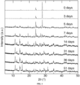
- the starting materials were loaded in the requisite stoichiometric ratios, thoroughly ground using an agate mortar and pestle, and allowed to rest in air for various amounts of time. In some experiments, the starting materials were allowed to rest for 7 days after mixing. Without wishing to be bound by any particular theory, the resting period may facilitate a pre-reaction, evidence for which is visible in FIG 1 . The pre-reaction is visible 5 days after mixing, as noted by the significant increase in new peaks in the diffractogram.
- Na 0.97 Eu 0.03 BaB 9 O 15 may be prepared via a microwave-assisted solid-state reaction. After resting the mixture of the initial starting materials for approximately 7 days, the resulting pre-reaction mixture was loaded into a graphite crucible that was centered in a larger alumina crucible with activated carbon packed into the annular space and covered by a graphite cap to maintain a reducing atmosphere comprising carbon monoxide produced by the hot carbon. The whole apparatus was then loaded into a microwave oven and reacted at ⁇ 480 W and -2450 Hz for 8 min.
- NaBaB 9 O 15 :Eu 2+ used a high-temperature ceramic route starting from the oxide powders.
- NBBO:Eu 2+ used a high-temperature ceramic route starting from the oxide powders.
- the X-ray powder diffractograms shown in FIG. 2 , most of the peaks can be indexed to calculated NaBaB 9 O 15 pattern.
- NaBaB 9 O 15 adopts the non-centrosymmetric trigonal space group R3c (no. 161). As illustrated in FIG.
- the crystal structure contains a three-dimensional framework of [B 3 O 7 ] 5- subunits in which two [BO 3 ] 3- trigonal planar units and one [BO 4 ] 5- tetrahedron are linked by the vertices.
- the arrangement of the [B 3 O 7 ] 5- units generates large tunnels along the [001] direction that are occupied by Ba 2+ and Na + alternatively.
- the Ba 2+ ions are coordinated in a nine-vertex distorted tri-capped trigonal prism, whereas six oxygen atoms form a highly distorted trigonal antiprism surrounding the Na + ions.
- the Eu 2+ substitutes for a small amount of Na + in this case.
- Na 0.97 Eu 0.03 BaB 9 O 15 has the largest unit cell volume among NaBaB 9 O 15 and NaBa 0.97 Eu 0.03 B 9 O 15 , because smaller Na + is substituted by larger Eu 2+ . Owing to the larger size of Ba 2+ than Eu 2+ , NaBa 0.97 Eu 0.03 B 9 O 15 possesses the smallest unit cell.
- Table 1 Refined crystallographic data of Na 0.97 Eu 0.03 BaB 9 O 15 , NaBaB 9 O 15 , and NaBa 0.97 Eu 0.03 B 9 O 15 .
- the single Eu 2+ site can also be supported by measuring the photoluminescence lifetime, as shown in FIG 5 .
- ⁇ -SiAlON:Eu 2+ emits an almost monochromatic light but contains some yellow component in it. Moreover, its harsh synthetic condition determines the high price of this phosphor in market. Both ⁇ -SiAlON:Eu 2+ and Ba 2 SiO 4 :Eu 2+ lie outside the National Television System Committee (NTSC) color triangle, which makes them off the standard and decreases the color quality in real application.
- NTSC National Television System Committee
- NBBO:Eu 2+ is clearly located in between Ba 2 SiO 4 :Eu 2+ and ⁇ -SiAlON:Eu 2+ in the color space, which moves this new phosphor's emission color closer to the green corner of the NTSC triangle, as shown, providing the potential to use this material in display applications.
- the CIE coordinates of blue-emitting BaMgAl 10 O 17 :Eu 2+ (BAM:Eu 2+ ) and red-emitting K 2 SiF 6 :Mn 4+ were also plotted.
- the triangle formed using NBBO:Eu 2+ as the green phosphor has an area that overlaps 78% of the NTSC area. This is a broader area than a device using ⁇ -SiAlON:Eu 2+ (69% of NTSC area) and Ba 2 SiO 4 :Eu 2+ (68% of NTSC area) by permitting more color in the green wavelength region.
Description
- This application claims the benefit of priority to
United States Provisional Application No. 62/877,603, filed on July 23, 2019 - The present invention relates generally to the fields of chemistry and physics. More particularly, it concerns phosphors that emit a narrow band of light as well as methods of making and light-emitting devices comprising said phosphors.
- Replacing a traditional light bulb with an energy-efficient, phosphor-converted white light emitting diode (pc-LED) is one of the easiest and most promising methods to decrease electricity consumption dramatically. The color gamut is determined by the red/green/blue (RGB) phosphors that fabricated in the LED devices. It is crucial to develop phosphors with proper optical properties to fulfill the application. Typically, the white emitting LED combines a near-UV emitting LED chip with β-SiAlON:Eu2+ as the green source, BaMgAl10O17:Eu2+ as the blue source, and K2SiF6:Mn4+ as the red source. Alternatively, it is possible to use a blue emitting LED chip along with a similar green source and similar red source. The discovery and development of efficient narrow green-emitting phosphors is of high importance as human eyes are more sensitive to green light than red and blue.
- Presently, only a few green phosphors are able to fulfill the commercial application, such as β-SiAlON:Eu2+ and Ba1.14Sr0.86SiO4:Eu2+, among others. Although β-SiAlON:Eu2+ is among the narrowest commercial green phosphors, its emission coordinates limit the maximum accessible color gamut. Moreover, another drawback is its harsh synthesis condition as it needs a high-pressure synthesis. In contrast, Ba1.14Sr0.86SiO4:Eu2+ is simple to make under normal atmospheric pressure. However, the broad emission band forbids its possibility of being widely used, in particular for display application. Also, the silicate efficiency drops fast at elevated temperature. Therefore, new inorganic solid-state rare earth phosphors with easily accessible synthesis conditions, narrow green emission, and excellent thermal stability are an urgent need.
- Phosphors having a composition similar to those of the present invention, but with shorter wavelength excitation and emission maxima, are known from Y. Zhuo et al., Nature Comm., 2018, 9, 4377. Specifically, Zhuo et al disclose a phosphor having the composition NaBa0.97Eu0.03B9O15.
- The present disclosure provides phosphors that efficiently and narrowly emit green light, methods for their manufacture, and light-emitting devices comprising said phosphors. In some embodiments, the phosphors provided herein emit green light in a narrower band than other phosphors in the art. The methods of producing the phosphors provided herein may be performed at atmospheric pressure and may be performed in air. The phosphors provided herein may possess emission coordinates that provide a color gamut more suitable to lighting applications than phosphors in the art. In some embodiments, the phosphors may be used in lighting applications. In some embodiments, the phosphors may be used for converting UV light to green light for use with a light-emitting diode (LED), laser diode (LD), or liquid crystal display (LCD), and a lighting or display apparatus employing the same.
- In some aspects, the present disclosure provides phosphors of the general molecular formula:
(A1-xEux)(Ba1-ySry)B9O15,
wherein:
A is one or more alkali metal;

- In some embodiments, A is a single alkali metal. In some embodiments, A is sodium. In some embodiments, A is sodium (I). In some embodiments, 0 ≤ y ≤ 0.75. In further embodiments, 0 ≤ y ≤ 0.50. In still further embodiments, 0 ≤ y ≤ 0.25. In some embodiments, y is 0. In some embodiments, 0 < x ≤ 0.15. In some embodiments, 0 < x ≤ 0.10. In some embodiments, 0 < x ≤ 0.05. In some embodiments, x is 0.03. In some embodiments, the phosphor is further defined as Na0.97Eu0.03BaB9O15. In some embodiments, a crystalline sample of the phosphor has a space group of R3c. In some embodiments, the phosphor has a decay time (τ) of from about 0.500 µs to about 1.500 µs. In some embodiments, τ is from about 1.000 µs to about 1.200 µs. In some embodiments, τ is about 1.103 µs. In some embodiments, the phosphor has an excitation spectrum peak at an excitation wavelength from about 350 nm to about 450 nm. In some embodiments, the excitation wavelength is from about 370 nm to about 435 nm. In some embodiments, the excitation wavelength is from about 390 nm to about 425 nm. In some embodiments, the excitation wavelength is from about 385 nm to about 405 nm. In some embodiments, the excitation wavelength is about 395 nm. In some embodiments, the excitation wavelength is from about 420 nm to about 440 nm. In some embodiments, the excitation wavelength is about 430 nm. In some embodiments, the phosphor has an emission spectrum peak at an emission wavelength from about 400 nm to about 650 nm. In some embodiments, the emission wavelength is from about 450 nm to about 550 nm. In some embodiments, the emission wavelength is from about 500 nm to about 525 nm. In some embodiments, the emission wavelength is about 515 nm. In some embodiments, the emission spectrum peak has a full width at half-maximum (FWHM) of from about 50 nm to about 90 nm. In some embodiments, the FWHM is from about 55 nm to about 75 nm. In some embodiments, the FWHM is from about 60 nm to about 70 nm. In some embodiments, the FWHM is about 64 nm. In some embodiments, the phosphor has a photoluminescence quantum yield (PLQY) greater than about 50%. In some embodiments, the phosphor has a PLQY is about 58%. In some embodiments, the phosphor has a PLQY greater than about 60%. In some embodiments, the phosphor has a PLQY greater than about 70%. In some embodiments, the PLQY is greater than about 80%. In some embodiments, the PLQY is about 87%.
- In other aspects, the present disclosure provides methods for producing a phosphor of the present disclosure, wherein the method comprises:
- a) mixing starting materials of the phosphor to produce a first reaction mixture;
- b) heating the first reaction mixture to produce the phosphor.
- In some embodiments, heating the first reaction mixture comprises irradiating with microwave radiation. In some embodiments, the frequency of the microwave radiation is from about 500 MHz to about 4400 MHz. In some embodiments, the frequency of the microwave radiation is from about 1000 MHz to about 3900 MHz. In some embodiments, the frequency of the microwave radiation is from about 2000 MHz to about 2900 MHz, such as about 2450 MHz. In some embodiments, the power of the microwave radiation is from about 120 W to about 1200 W. In some embodiments, the power of the microwave radiation is from about 240 W to about 900 W. In some embodiments, the power of the microwave radiation is from about 360 W to about 600 W, such as about 480 W.
- In still other aspects, the present disclosure provides methods for producing a phosphor of the present disclosure, wherein the method comprises:
- a) mixing starting materials of the phosphor to produce a first reaction mixture;
- b) heating the first reaction mixture to a first temperature to produce a second reaction mixture; and
- c) heating the second reaction mixture to a second temperature to produce the phosphor.
- In some embodiments, the starting materials of the phosphor comprise one or more alkali metal sources, a barium source, a boron source, and a europium source. In some embodiments, the starting materials of the phosphor comprise a single alkali metal source. In some embodiments, the alkali metal source is a sodium source. In some embodiments, the sodium source is a sodium salt, such as NaHCO3. In some embodiments, the barium source is a barium salt, such as BaCO3. In some embodiments, the boron source is H3BO3. In some embodiments, the europium source is a europium oxide, such as europium (III) oxide. In some embodiments, heating the first reaction mixture comprises heating in a furnace. In some embodiments, the first temperature is from about 400 °C to 800 °C. In some embodiments, the first temperature is from about 500 °C to about 700 °C. In some embodiments, the first temperature is from about 550 °C to about 650 °C. In some embodiments, the first temperature is about 600 °C. In some embodiments, heating the second reaction mixture comprises heating in a furnace. In some embodiments, the second temperature is from about 525 °C to 925 °C. In some embodiments, the second temperature is from about 625 °C to about 825 °C. In some embodiments, the second temperature is from about 675 °C to about 775 °C. In some embodiments, the second temperature is about 725 °C.
- In some embodiments, mixing is performed in air. In some embodiments, heating the first reaction mixture is performed in air. In some embodiments, heating the first reaction mixture is performed in a reducing atmosphere. In some embodiments, the heating the second reaction mixture is performed in a reducing atmosphere. In some embodiments, the reducing atmosphere comprises H2, CO, or NH3. In some embodiments, the reducing atmosphere comprises CO. In some embodiments, the reducing atmosphere comprises H2. In some embodiments, the reducing atmosphere further comprises a diluent gas. In some embodiments, the diluent gas is N2, helium, neon, argon, krypton, xenon, or any combination thereof. In some embodiments, the reducing atmosphere comprises argon. In some embodiments, the reducing atmosphere comprises N2. In some embodiments, the reducing atmosphere comprises H2 and argon. In some embodiments, the reducing atmosphere comprises H2 and N2. In some embodiments, the reducing atmosphere comprises from about 0.1% to about 25% H2. In some embodiments, the reducing atmosphere comprises from about 1% to about 10% H2. In some embodiments, the reducing atmosphere comprises about 5% H2. In some embodiments, the reducing atmosphere comprises from about 75% to about 99.9% N2. In some embodiments, the reducing atmosphere comprises from about 90% to about 99% N2. In some embodiments, the reducing atmosphere comprises about 95% N2.
- In some embodiments, the method further comprises resting the first reaction mixture for at least about 12 hours before heating. In some embodiments, heating the first reaction mixture comprises the method further comprises resting the first reaction mixture for at least about 1 day before heating. In some embodiments, the method further comprises resting the first reaction mixture for at least about 3 days before heating. In some embodiments, the method further comprises resting the first reaction mixture for at least about 4 days before heating. In some embodiments, the method further comprises resting the first reaction mixture for at least about 7 days before heating. In some embodiments, the method further comprises resting the first reaction mixture for about 7 days before heating. In some embodiments, resting is performed in an accelerated aging chamber. In some embodiments, the accelerated aging chamber produces elevated temperature and/or humidity relative to the ambient temperature and/or humidity. In some embodiments, the methods may be performed at atmospheric pressure.
- In yet other aspects, the present disclosure provides light-emitting devices comprising:
- a) an excitation light source that emits primary light; and
- b) a phosphor according to any one of claims 1-6,
- In some embodiments, the phosphor is a green-emitting phosphor. In some embodiments, the excitation light source is a semiconductor light source, such as a light-emitting diode (LED) or a laser diode (LD). In some embodiments, the primary light has a wavelength from about 380 nm to about 500 nm. In some embodiments, the primary light has a wavelength from about 390 nm to about 425 nm. In some embodiments, the primary light has a wavelength of about 395 nm. In some embodiments, the primary light has a wavelength from about 390 nm to about 435 nm. In some embodiments, the primary light has a wavelength of about 430 nm. In some embodiments, the light-emitting device further comprises a blue-emitting phosphor. In some embodiments, the light-emitting device further comprises a red-emitting phosphor. In some embodiments, the light-emitting device further comprises a blue-emitting phosphor and a red-emitting phosphor.
- Other objects, features and advantages of the present invention will become apparent from the following detailed description. It should be understood, however, that the detailed description and the specific examples, while indicating specific embodiments of the invention, are given by way of illustration only. Note that simply because a particular compound is ascribed to one particular generic formula doesn't mean that it cannot also belong to another generic formula.
- The following drawings form part of the present specification and are included to further demonstrate certain aspects of the present disclosure. The disclosure may be better understood by reference to one or more of these drawings in combination with the detailed description of specific embodiments presented herein.
-
FIG. 1 shows XRD patterns of the initial reaction necessary to make the first reaction mixture. The initial peaks at 0 days correspond to only starting materials whereas ~5 days after the initial mixture the reaction has started as indicated by the change in the diffraction peaks. -
FIG. 2 shows XRD patterns of NBBO:Eu2+ prepared using a furnace route and a microwave-based route. The calculated pattern is shown on the bottom of the spectrum. Impurity (BaB8O13) peaks are marked by asterisks. -
FIGS.3A-3C show the Rietveld refinement of synchrotron X-ray powder diffraction data. The observed data are in black circles, the fit is colored gray, the difference between the data and the fit is shown by black curve, and the Bragg positions are black bars.FIG. 3A shows the results for Na0.97Eu0.03BaB9O15.FIG. 3B shows the results for NaBaB9O15.FIG. 3C shows the result for NaBa0.97Eu0.03B9O15. -
FIGS. 4A & 4B show the crystal structure of NaBaB9O15.FIG. 4A shows the crystal structure viewed in [010] direction with the associated [BaO9], [NaO6], and [B3O7] polyhedral subunits highlighted.FIG. 4B shows the arrangement of the [B3O7]5- units generate large tunnels along the [001] direction, which are alternately filled by Ba2+ and Na+. -
FIG. 5 shows the luminescence decay curve of NBBO:Eu2+. The fit line is obtained followingEquation 1 to obtain the decay time (τ). -
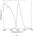
FIG. 6 shows the room temperature excitation spectrum (left line with lesser peak at 395 nm) and emission (right line with peak at 515 nm) spectra of NBBO:Eu2+. Emission spectrum was obtained upon excitation at 395 nm. -
FIG. 7 shows the room temperature CIE coordinates of NBBO:Eu2+ excited at 395 nm (circle), Ba2SiO4:Eu2+ (nabla), β-SiAlON:Eu2+ (square), BAM:Eu2+ (diamond), and K2SiF6:Mn4+ (triangle). Plotted in with dashed lines and without marker symbols is the NTSC color space. -
FIG. 8 shows the room temperature photoluminescence quantum yield (Φ) values of NBBO:Eu2+ excited at different wavelengths. - Disclosed herein are new phosphors with efficient and narrow light-emission properties, methods for their manufacture, and light-emitting devices comprising said phosphors. In some embodiments, the phosphor emits in the green region of the electromagnetic spectrum when excited with n-UV or blue light. In some embodiments, the phosphors exhibit a narrower emission band than other green phosphors in art. In some embodiments, the phosphors may be synthesized by a simple multi-step high temperature solid-state furnace reaction under normal atmospheric pressure. In other embodiments the phosphors may be synthesized using a rapid microwave-based reaction under normal atmospheric pressure. In some embodiments, the phosphors have a high photoluminescence quantum yield and are thermally robust at elevated temperature. In some embodiments, the phosphors exhibit optical properties suitable for general white illumination. In some embodiments, the phosphor has optical properties suitable for LED backlighting or similar display applications. In some embodiments, the phosphor is Na0.97Eu0.03BaB9O15.
- The compounds of the present invention (also referred to as "phosphors," "phosphors of the present disclosure" or "phosphors disclosed herein") are shown, for example, above, in the summary of the invention section, in the Examples below, and in the claims below. They may be made using the synthetic methods outlined in the Examples section. These methods can be further modified and optimized using the principles and techniques of inorganic chemistry as applied by a person skilled in the art. Such principles and techniques are taught, for example, in Cotton and Wilkinson, Advanced Inorganic Chemistry, (1998). In addition, the synthetic methods may be further modified and optimized for preparative, pilot- or large-scale production, either batch or continuous, using the principles and techniques of process chemistry as applied by a person skilled in the art.
- In some embodiments, the compounds of the present invention have the advantage that they may be more efficacious than, more efficient than, more easily manufactured than, more thermally stable than, and/or have a better photophysical properties (e.g., narrower emission band and/or higher optical yield) than, and/or have other useful physical or chemical properties over, compounds known in the prior art, whether for use in the applications stated herein or otherwise.
- Atoms making up the compounds of the present invention are intended to include all isotopic forms of such atoms. Isotopes, as used herein, include those atoms having the same atomic number but different mass numbers. By way of general example and without limitation, isotopes of hydrogen include tritium and deuterium, and isotopes of carbon include 13C and 14C.
- In some embodiments, the present disclosure provides methods for producing phosphors of the present disclosure. Such methods comprise mixing starting materials of the phosphor to produce a first reaction mixture; heating the first reaction mixture to a first temperature to produce a second reaction mixture; heating the second reaction mixture to a second temperature to produce the phosphor. The starting materials of the phosphor comprise one or more sources of inorganic elements, such as alkali metal sources, alkaline earth metal sources, boron sources, and lathanide sources. Non-limiting examples of alkali metal sources include lithium, sodium, potassium, and rubidium sources, such as sodium salts (e.g., NaHCO3). In some embodiments, the starting materials comprise one or more alkali metal sources. In some embodiments, the one or more alkali metal sources comprise the same alkali metal element (e.g., NaHCO3 and Na2CO3). In some embodiments, the one or more alkali metal sources comprise different alkali metal elements (e.g., NaHCO3 and KHCO3). Non-limiting examples of alkaline earth metal sources include strontium and barium sources, such as barium salts (e.g., BaCO3). Non-limiting examples of boron sources include boric acid (i.e., H3BO3) and borate salts, including but not limited to monoborates, diborates, triborates, and tetraborates. Non-limiting examples of lanthanide sources include europium, cerium, yttrium, terbium, and gadolinium sources, such as europium oxides (e.g., EU2O3).
- Few green phosphors in the art possess a narrow emission band width, mild synthesis conditions, and widely applicable emission coordinates, which are of particular importance for display lighting applications. For example, β-SiAlON:Eu2+ is among the narrowest commercial green phosphors; however, its emission coordinates limit the maximum accessible color gamut and its synthesis requires harsh conditions including high-pressure (see Hirosaki et al., 2005). Ba1.14Sr0.86SiO4:Eu2+, another green phosphor, while able to be synthesized under normal atmospheric pressure, exhibits a broad emission band, which precludes its wide applicability (see Denault et al., 2014).
- The phosphors of the present disclosure may be prepared at atmospheric pressure and exhibit a narrow green emission band (see
FIG. 6 ) and exhibit emission coordinates that are desirable in many applications, such as display lighting (seeFIG. 7 ). In some embodiments, the phosphors of the present disclosure exhibit an emission spectrum peak with a full width at half-maximum (FWHM) of from about 50 nm to about 90 nm, from about 55 nm to about 75 nm, from about 50 to about 70 nm, from about 60 nm to about 70 nm, or from about 50 nm, 55 nm, 60 nm, 65 nm, 70 nm, 75 nm, 80 nm, or 85 nm to about 90 nm, or any range derivable therein. In some embodiments, the FWHM is about 64 nm. - In some embodiments, the first reaction mixture is prepared by combining the starting materials in the appropriate stoichiometric ratios. In some embodiments, the starting materials are mixed and ground by hand using a mortar and pestle. In other embodiments, the starting materials are mixed and ground using mechanical methods including, stirring or blending in a high-speed blender or a ribbon blender, or using a ball mill, a shaker mill, or a jar mill. In some embodiments, mixing further comprises mixing media. Non-limiting examples of mixing media include solvents, such as ethanol. In some embodiments, the first reaction mixture is rested in air before heating. In some embodiments, the first reaction mixture is rested in air for at least 12 hours. In some embodiments, the first reaction mixture is rested in air for at least about 7 days. In some embodiments, the first reaction mixture is rested in air for from about 1 day to about 14 days, from about 3 days to about 12 days, from about 5 days to about 9 days, or for about 7 days before heating. In some embodiments, the first reaction mixture is rested in air for from about 1, 2, 3, 4, 5, 6, 7, 8, 9, 10, 11, 12, 13, 14, 15, 16, 17, 18, 19, 20, 21, 22, 23, 24, 25, 26, 27, 28, 29, 30, 31, 32, 33, 34, 35, 36, 37, 38, 39, 40, 41, 42, 43, 44, 45, 46, 47, 48, 49, 50, 51, 52, 53, 54, 55, 56, 57, 58, 59, to about 60 days or any range derivable therein.
- In some embodiments, the first reaction mixture is heated at a temperature from about 400 °C to 800 °C, from about 500 °C to about 700 °C, from about 550 °C to about 650 °C, or from about 400 °C, 420 °C, 440 °C, 460 °C, 480 °C, 500 °C, 520 °C, 540 °C, 560 °C, 580 °C, 600 °C, 620 °C, 640 °C, 660 °C, 680 °C, 700 °C, 720 °C, 720 °C, 740 °C, 760 °C, or 780 °C to about 800 °C or any range derivable therein. In some embodiments, the first reaction temperature is about 600 °C. In some embodiments, the second reaction temperature is from about 525 °C to 925 °C, from about 625 °C to about 825 °C, from about 675 °C to about 775 °C, or from about 525 °C, 550 °C, 575 °C, 600 °C, 625 °C, 650 °C, 675 °C, 700 °C, 725 °C, 750 °C, 775 °C, 800 °C, 825 °C, 850 °C, 875 °C, or 900 °C, to about 925 °C or any range derivable therein. In some embodiments, the second reaction temperature is about 725 °C.
- In other embodiments, the first reaction mixture is heated with microwave radiation with a frequency from about 500 MHz to about 4400 MHz, from about 1000 MHz to about 3900 MHz, from about 2000 MHz to about 2900 MHz, or from about 500 MHz, 1000 MHz, 1500 MHz, 2000 MHz, 2500 MHz, 3000 MHz, 3500 MHz, or 4000 MHz to about 4400 MHz, or any range derivable therein. In some embodiments, the power of the microwave radiation is from about 120 W to 1200 W, from about 240 W to about 900 W, from about 360 W to 600 W, or from about 120 W, 240 W, 360 W, 480 W, 600 W, 720 W, 840 W, 960 W, or 1080 W to about 1200 W or any range derivable therein.
- In some embodiments, heating the first reaction mixture is performed under an atmosphere of air. In some embodiments, heating the second reaction mixture is performed under a reducing atmosphere. In some embodiments, the reducing atmosphere comprises a reducing gas such as hydrogen, carbon monoxide, ammonia, or any combination thereof. In some embodiments, the reducing atmosphere further comprises a diluent gas, such as nitrogen, helium, neon, argon, krypton, xenon, or any combination thereof. In some embodiments, the reducing atmosphere is produced by heating high-purity carbon particles in air so that the carbon particles react with the oxygen present in air, thereby, generating the reducing gas, carbon monoxide. In some embodiments, the reducing atmosphere comprises H2 and N2. In some embodiments, the reducing atmosphere comprises from about 0.1% to about 25% H2, from about 1% to about 10% H2, or from about 0.1%, 0.2%, 0.3%, 0.4%, 0.5%, 0.6%, 0.7, 0.8%, 0.9%, 1%, 2%, 3%, 4%, 5%, 6%, 7%, 8%, 9%, 10%, 12%, 14%, 16%, 18%, or 20% to about 25% H2 or any range derivable therein. In some embodiments, the reducing atmosphere comprises about 5% H2. In some embodiments, the reducing atmosphere comprises from about 75% to about 99.9% N2, from about 90% to about 99% N2, or from about 75%, 80%, 85%, 90%, 91%, 92%, 93%, 94%, 95%, 96%, 97%, 98%, 99%, 99.1%, 99.2%, 99.3%, 99.4%, 99.5%, 99.6%, 99.7%, 99.8%, to about 99.9% N2 or any range derivable therein. In some embodiments, the reducing atmosphere comprises about 95% N2.
- White light is a mixture of different wavelengths of light, and thus it is possible to characterize white light based on the component colors used to generate it. Different colors may be combined to generate white light, including but not limited to: 1) red, green, and blue, 2) light blue, amber, and lavender, and 3) cyan, magenta, and yellow. Further, a combination of only two colors may be combined to generate light that still appears white to the eye if these two chosen colors are so-called complementary, and an example of this is narrow band sources (LEDs, or in the extreme case, lasers) emitting around 635 nm and 493 nanometers. These artificial whites may appear white to the human eye, but in other ways inferior to full spectrum light and/or natural sunlight in that they will appear artificial when shown on a colored surface.
- A classification system developed to characterize the quality of white light, the Color Rendering Index (CRI), was developed in 1965 by the Commission Internationale de l'Eclairage (CIE). A summary of their recommendations is reviewed in
U.S. Pat. No. 7,387,405 . The CIE advised a measuring the color rendering properties of light sources based on a sample test color method. This method has been updated and is described in "Method of Measuring and Specifying Color Rendering Properties of light sources," 1995. - The method involves the spectroradiometric measurement of the light source being tested. This data is multiplied by the reflectance spectrums of eight color sample. The resulting spectrums are then converted to tristimulus values based on the
CIE 1931 standard observer. The shift of these values with respect to a reference light are determined for the uniform color space (UCS) recommended in 1960 by the CIE. The average of the eight color shifts is calculated to generate the General Color Rendering Index, known as the CRI. Within these calculations the CRI is scaled so that a perfect score equals 100, where "perfect" means using a source spectrally equal to a reference source (often sunlight and/or full spectrum light). - Artificial lighting generally uses the standard CRI to determine the quality of white light. If a white light yields a high CRI compared to sunlight and/or a full spectrum light, then it is considered to have a better quality in that it is more "natural," and more likely to enable a colored surface to be rendered better. In addition to providing better quality white light, it may also be desirable to produce specific colors of light, because, for example, as natural light tends to be more orange to red in the morning, and bluer in the night or evening, the ability to change, fine-tune, or control a specific color or range of colors within the full spectrum is also important.
- In some embodiments, the phosphors of the present disclosure may be used in the manufacture of photoluminescence wavelength conversion materials for solid-state light-emitting devices, including but not limited to LEDs. In some embodiments, the phosphors may be deposited directly onto the LED chips to produce photoluminescence wavelength converted solid-state light emitting devices. In some embodiments, the phosphors of the present disclosure may be used in conjunction with one or more additional phosphors to produce white light and/or to increase the CRI. The additional one or more phosphors may include but are not limited to silicate-based phosphors, aluminate-based phosphors, nitride-based phosphors, sulfate-based phosphors, YAG phosphors or mixtures thereof. In some embodiments, the light-emitting devices of the present disclosure further comprise a red-emitting phosphor and a blue-emitting phosphor. Non-limiting examples of red light-emitting phosphors include K2SiF6:Mn4+ and nitride-based phosphors, such as those taught in
U.S. Pat. No. 8,597,545 or8,663,502 . - Non-limiting examples of blue light-emitting phosphors include aluminate-based phosphors, such as BaMgAl10O17:Eu2+.
- The present disclosure provides inorganic compounds comprising atoms of one or more elements. In the context of the present disclosure, reference to an element is intended to refer to atoms of that element in any oxidation state. A non-limiting example is the term "sodium" (i.e., Na) which refers to both sodium metal (i.e., Na0) and sodium(I) (i.e., Na+).
- A "repeat unit" is the simplest structural entity of certain materials, for example, frameworks and/or polymers, whether organic, inorganic or metal-organic. In the case of a polymer chain, repeat units are linked together successively along the chain, like the beads of a necklace. For example, in polyethylene, -[-CH2CH2-]n-, the repeat unit is -CH2CH2-. The subscript "n" denotes the degree of polymerization, that is, the number of repeat units linked together. When the value for "n" is left undefined or where "n" is absent, it simply designates repetition of the formula within the brackets as well as the polymeric nature of the material. The concept of a repeat unit applies equally to where the connectivity between the repeat units extends three dimensionally, such as crystalline inorganic materials, metal organic frameworks, modified polymers, thermosetting polymers, etc.
- The use of the word "a" or "an," when used in conjunction with the term "comprising" in the claims and/or the specification may mean "one," but it is also consistent with the meaning of "one or more," "at least one," and "one or more than one."
- Throughout this application, the term "about" is used to indicate that a value includes the inherent variation of error for the device, the method being employed to determine the value, or the variation that exists among the study subjects or patients. When the term "about" is used in the context of X-ray diffraction peaks, the term is used to express variation in the peak of ± 0.2 °2θ.
- The terms "comprise," "have," and "include" are open-ended linking verbs. Any forms or tenses of one or more of these verbs, such as "comprises," "comprising," "has," "having," "includes," and "including," are also open-ended. For example, any method that "comprises," "has," or "includes" one or more steps is not limited to possessing only those one or more steps and also covers other unlisted steps.
- The term "effective," as that term is used in the specification and/or claims, means adequate to accomplish a desired, expected, or intended result.
- An "isomer" of a first compound is a separate compound in which each molecule contains the same constituent atoms as the first compound, but where the configuration of those atoms in three dimensions differs.
- The above definitions supersede any conflicting definition in any reference that is referred to herein.
- The fact that certain terms are defined, however, should not be considered as indicative that any term that is undefined is indefinite. Rather, all terms used are believed to describe the invention in terms such that one of ordinary skill can appreciate the scope and practice the present invention.
- As used herein, one or more of the following abbreviations may be used in the application: LED, light-emitting diode; pc-LED, phosphor-converted while light emitting diode; n-UV, near ultraviolet; FWHM, full width at half-maximum; PLQY or Φ, photoluminescence quantum yield; h, hour; and rt, room temperature.
- The following examples are included to demonstrate preferred embodiments of the invention. It should be appreciated by those of skill in the art that the techniques disclosed in the examples which follow represent techniques discovered by the inventor to function well in the practice of the invention, and thus can be considered to constitute preferred modes for its practice.
- NaHCO3 (99.7%) was procured from EM science, BaCO3 (98%) was procured from Johnson Matthey, H3BO3 (99.999%) was procured from Sigma-Aldrich, and Eu2O3 (99.9%) was procured from Materion Advanced Chemicals. Photoluminescent spectra were recorded on a Horiba Fluoromax-4 fluorescence spectrophotometer with a 75 W xenon arc lamp. The sample was mixed into silicone resin (GE Silicones, RTV615) and deposited on a quartz substrate (Chemglass). The luminescence lifetime decay measurements were collected using a Horiba DeltaFlex Lifetime System equipped with a NanoLED N-390 nm LED (λex = 392 nm) and a 450 nm long-pass filter. A total measurement length of 13 µs was employed using a repetition rate of 50 kHz and a delay of 10 ns. The absolute internal quantum yield was determined by placing the sample inside a Spectralon-coated integrating sphere (150 mm diameter, Labsphere) and exciting by n-UV through blue light of different wavelengths. The photoluminescence quantum yield (PLQY) was calculated on the basis of disclosed methods (see de Mello et al., 1997; and Leyre et al., 2014).
- Phase purity was confirmed by X-ray powder diffraction on a PanAnalytical X'Pert powder diffractometer using Cu Kα radiation (1.54183 Å).
- Na0.97Eu0.03BaB9O15 was prepared via solid-state reactions starting from NaHCO3, BaCO3, H3BO3, and Eu2O3. The starting materials were loaded in the requisite stoichiometric ratios, thoroughly ground using an agate mortar and pestle, and allowed to rest in air for various amounts of time. In some experiments, the starting materials were allowed to rest for 7 days after mixing. Without wishing to be bound by any particular theory, the resting period may facilitate a pre-reaction, evidence for which is visible in
FIG 1 . The pre-reaction is visible 5 days after mixing, as noted by the significant increase in new peaks in the diffractogram. These new peaks continue to grow in intensity while the original large peaks near ~25° and ~30° 2θ to decrease in prominence. This process continues for about 30 days when the pre-reaction mixture stabilizes. The minimum waiting time necessary to maximize the production of the green-emitting phosphor appears to be -7 days. The X-ray powder diffractograms of the starting mixture over time are shown inFIG. 1 . This pre-reaction mixture was then subsequently sintered at 600 °C for 2 h in air to decompose the reagents and initiate the reaction. The samples were then ground and heated at 725 °C for 30 h using a fused silica tube furnace under a weak reducing atmosphere (5% H2/95% N2) with heating and cooling ramps of 3 °C min-1. - Alternatively, Na0.97Eu0.03BaB9O15 may be prepared via a microwave-assisted solid-state reaction. After resting the mixture of the initial starting materials for approximately 7 days, the resulting pre-reaction mixture was loaded into a graphite crucible that was centered in a larger alumina crucible with activated carbon packed into the annular space and covered by a graphite cap to maintain a reducing atmosphere comprising carbon monoxide produced by the hot carbon. The whole apparatus was then loaded into a microwave oven and reacted at ~480 W and -2450 Hz for 8 min.
- The synthesis of NaBaB9O15:Eu2+ (NBBO:Eu2+) used a high-temperature ceramic route starting from the oxide powders. According to the X-ray powder diffractograms, shown in
FIG. 2 , most of the peaks can be indexed to calculated NaBaB9O15 pattern. The small amount of tiny impurity peaks, marked by asterisks, belongs to BaB8O13, whose emission is not observed in the following optical characterizations. NaBaB9O15 adopts the non-centrosymmetric trigonal space group R3c (no. 161). As illustrated inFIG. 4 , the crystal structure contains a three-dimensional framework of [B3O7]5- subunits in which two [BO3]3- trigonal planar units and one [BO4]5-tetrahedron are linked by the vertices. The arrangement of the [B3O7]5- units generates large tunnels along the [001] direction that are occupied by Ba2+ and Na+ alternatively. The Ba2+ ions are coordinated in a nine-vertex distorted tri-capped trigonal prism, whereas six oxygen atoms form a highly distorted trigonal antiprism surrounding the Na+ ions. The Eu2+ substitutes for a small amount of Na+ in this case. - According to Rietveld refinements on the synchrotron X-ray diffraction data (
FIGS. 4A- 4C and Table 1), Na0.97Eu0.03BaB9O15 has the largest unit cell volume among NaBaB9O15 and NaBa0.97Eu0.03B9O15, because smaller Na+ is substituted by larger Eu2+. Owing to the larger size of Ba2+ than Eu2+, NaBa0.97Eu0.03B9O15 possesses the smallest unit cell. These data support that the substitution of Eu2+ for Na+ produce discrete and discernable difference from the case where Eu2+ substitutes for Ba2+.Table 1: Refined crystallographic data of Na0.97Eu0.03BaB9O15, NaBaB9O15, and NaBa0.97Eu0.03B9O15. Formula Na0.97Eu0.03BaB9O15 NaBaB9O15 NaBa0.97Eu0.03B9O15 Radiation type; λ (Å) Synchrotron radiation; 0.412824 Synchrotron radiation; 0.457667 Synchrotron radiation; 0.412824 Lattice parameters (Å) a = 11.10911(7) a = 11.10166(6) a = 11.09060(1) c = 17.39509(6) c = 17.40089(4) c = 17.41663(6) Unit cell volume (Å3) 1859.15(9) 1857.28(5) 1855.26(1) Profile R-factor, R p 0.0840 0.0739 0.0874 Weighted profile R-factor, R wp 0.1090 0.0907 0.1144 - The single Eu2+ site can also be supported by measuring the photoluminescence lifetime, as shown in
FIG 5 . The data could be fit with a single exponential function described in Eq. 1:
- Substituting Eu2+ for Na+ in the structure leads to photoluminescence upon excitation with light ranging from 280 nm to ~480 nm, making NBBO:Eu2+ exceptionally versatile as it can be excited by a plethora of sources throughout the UV to blue regions of the electromagnetic spectrum. The emission spectrum is also depicted in
FIG. 6 when λex = 395 nm, showing a narrow emission band with a maximum centered at 515 nm and a full width at half-maximum (fwhm) of approximately 64 nm. The narrow fwhm of this phosphor is comparable to the current narrowest green commercial phosphor, β-SiAlON:Eu2+ (fwhm = 55 nm), and is significantly narrower than most other green phosphors including the well-known Ba2SiO4:Eu2+ (fwhm = 80 nm) and Y3(Al,Ga)5O12:Ce3+ (120 nm). NBBO:Eu2+ emission spectrum were also measured using blue excitation sources (λex = 430 nm and 450 nm respectively) and found to exhibit the same peak shape and peak position, with the narrow emission maintained similar to excitation at shorter wavelengths. - Besides its narrow fwhm, the NBBO:Eu2+has other advantages that can be best understood by analyzing the room temperature emission spectrum with the tristimulus function. Plotting the color coordinates of NBBO:Eu2+ (λex = 395 nm), the industry standard green phosphors β-SiAlON:Eu2+ and Ba2SiO4:Eu2+ on a 1931 CIE diagram, illustrated in
FIG. 7 , allows for comparison of the raw color of these three phosphors. Ba2SiO4:Eu2+ is on the very left of the color space among these three due to its shorter emission wavelength, which gives its emission a blue hint, which diminishes the color purity. β-SiAlON:Eu2+, however, emits an almost monochromatic light but contains some yellow component in it. Moreover, its harsh synthetic condition determines the high price of this phosphor in market. Both β-SiAlON:Eu2+ and Ba2SiO4:Eu2+ lie outside the National Television System Committee (NTSC) color triangle, which makes them off the standard and decreases the color quality in real application. On the other hand, NBBO:Eu2+ is clearly located in between Ba2SiO4:Eu2+ and β-SiAlON:Eu2+ in the color space, which moves this new phosphor's emission color closer to the green corner of the NTSC triangle, as shown, providing the potential to use this material in display applications. To ascertain the available color gamut by incorporating NBBO:Eu2+, the CIE coordinates of blue-emitting BaMgAl10O17:Eu2+ (BAM:Eu2+) and red-emitting K2SiF6:Mn4+were also plotted. Comparing the area of the resulting triangle created by connecting the coordinates for BAM:Eu2+- NBBO:Eu2+-K2SiF6:Mn4+ with the triangle created by BAM:Eu2+-β-SiAlON:Eu2+-K2SiF6:Mn4+ and BAM:Eu2+-Ba2SiO4:Eu2+-K2SiF6:Mn4+ shows that using NBBO:Eu2+ widens the color gamut by 6% and 4% than if β-SiAlON:Eu2+ and Ba2SiO4:Eu2+ were used. Further, the triangle formed using NBBO:Eu2+ as the green phosphor has an area that overlaps 78% of the NTSC area. This is a broader area than a device using β-SiAlON:Eu2+ (69% of NTSC area) and Ba2SiO4:Eu2+ (68% of NTSC area) by permitting more color in the green wavelength region. - Although this phosphor has a narrow emission spectrum, to be useful, NBBO:Eu2+ must also have a high efficiency. Therefore, the room temperature photoluminescence quantum yield (Φ) was measured to assess the phosphor's internal efficiency. Because of the wide excitation spectrum, the Φ was calculated using multiple excitation wavelengths to understand its efficiency across n-UV to blue region. As presented in
FIG. 8 , the Φ for this phosphor using λex = 400 nm exhibits a high Φ nearly 90%, which should allow this compound to be a viable green component in devices employing a 400 nm LED chip. Exciting at a slightly longer wavelength (λex = 410 nm) causes a minor decrease in the Φ to 83%, which can retain up to λex = 430 nm. Further red shifting the excitation source decreases the Φ. However, this phosphor still maintains an Φ of nearly 60% when excited by blue light (λex = 450 nm). The optical properties of NBBO:Eu2+ across the n-UV to blue region, narrow emission peak, and green color coordinates indicate that this new green phosphor may find wide use in devices employing n-UV and blue excitation. - All of the compositions and methods disclosed and claimed herein can be made and executed without undue experimentation in light of the present disclosure.
-
-
7,387,405 -
8,597,545 -
8,663,502 - Commission Internationale de l'Eclairage, "Method of Measuring and Specifying Color Rendering Properties of light sources," 13(3), 1995.
- Cotton and Wilkinson, Advanced Inorganic Chemistry, 5th ed., 1988.
- de Mello et al., Adv. Mater., 9:230-232, 1997.
- Denault et al., Chem. Mater., 26:2275-2282, 2014.
- Hirosaki et al., Appl. Phys. Lett., 86:211905, 2005.
- Leyre et al., Rev. Sci. Instrum., 85:123115, 2014.
Claims (15)
- A phosphor of the general molecular formula:
(A1-xEux)(Ba1-ySry)B9O15,
wherein:
A is one or more alkali metal;

- The phosphor of claim 1, wherein A is sodium (I).
- The phosphor of either claim 1 or claim 2, wherein 0 ≤ y ≤ 0.75, such as 0.
- The phosphor according to any one of claims 1-3, wherein 0 < x ≤ 0.15, such as 0.03.
- The phosphor according to any one of claims 1-4, further defined as Na0.97Eu0.03BaB9O15.
- The phosphor according to any one of claims 1-5, wherein the phosphor has an excitation spectrum peak at an excitation wavelength from about 350 nm to about 450 nm, such as 395 nm or 430 nm, the phosphor has an emission spectrum peak at an emission wavelength from about 450 nm to about 550 nm, such as about 515 nm, and/or the emission spectrum peak has a full width at half-maximum (FWHM) of from about 50 nm to about 90 nm, such as about 64 nm.
- A method for producing a phosphor according to any one of claims 1-6, wherein the method comprises:a) mixing starting materials of the phosphor to produce a first reaction mixture, wherein the starting materials of the phosphor comprise one or more alkali metal sources, a barium source, a boron source, and a europium source;b) heating the first reaction mixture to produce the phosphor.
- The method of claim 7, wherein heating the first reaction mixture comprises irradiating the first reaction mixture with microwave radiation, optionally, wherein the frequency of the microwave radiation is from about 500 MHz to about 4400 MHz, such as about 2450 MHz and/or the power of the microwave is from about 120 W to about 1200 W, such as about 480 W.
- A method for producing a phosphor according to any one of claims 1-6, wherein the method comprises:a) mixing starting materials of the phosphor to produce a first reaction mixture, wherein the starting materials of the phosphor comprise one or more alkali metal sources, a barium source, a boron source, and a europium source;b) heating the first reaction mixture to a first temperature to produce a second reaction mixture; andc) heating the second reaction mixture to a second temperature to produce the phosphor.
- The method according to any one of claims 7-9, wherein the alkali metal source is a sodium source is a sodium salt, such as NaHCO3, the barium source is a barium salt, such as BaCO3, the boron source is H3BO3, and/or the europium source is a europium salt, such as europium (III) oxide.
- The method according to any one of claims 7-10, wherein the first temperature is from about 400 °C to 800 °C, such as about 600 °C, optionally wherein heating the first reaction mixture comprises irradiating with microwave radiation or comprises heating in a furnace; and/or
wherein mixing is performed in air and heating the first reaction mixture is performed in air or in a reducing atmosphere. - The method according to any one of claims 9-11, wherein the second temperature is from about 525 °C to 925 °C, such as about 725 °C, optionally wherein heating the second reaction mixture comprises heating in a furnace; and/or
wherein heating the second reaction mixture is performed in a reducing atmosphere. - The method according to any one of claims 7-12, wherein the reducing atmosphere comprises H2, CO, or NH3, and optionally further comprises a diluent gas, such as N2, helium, neon, argon, krypton, xenon, or any combination thereof and/or the method further comprises resting the first reaction mixture for at least about 12 hours before heating, such as about 3, 4, 5, 6, or 7 days.
- A light-emitting device comprising:a) an excitation light source that emits primary light; andb) a phosphor according to any one of claims 1-6, wherein the phosphor is a green-emitting phosphor.
- The light-emitting device of claim 14, wherein the excitation light source is a semiconductor light source, such as a light-emitting diode (LED) or laser diode (LD), the primary light has a wavelength from about 380 nm to about 500 nm, such as about 395 nm or about 430 nm, and/or the light-emitting device further comprises a blue-emitting phosphor, a red-emitting phosphor, or a combination thereof.
Applications Claiming Priority (2)
| Application Number | Priority Date | Filing Date | Title |
|---|---|---|---|
| US201962877603P | 2019-07-23 | 2019-07-23 | |
| PCT/US2020/043167 WO2021016411A1 (en) | 2019-07-23 | 2020-07-23 | Narrow green-emitting phosphors |
Publications (2)
| Publication Number | Publication Date |
|---|---|
| EP4004144A1 EP4004144A1 (en) | 2022-06-01 |
| EP4004144B1 true EP4004144B1 (en) | 2023-05-24 |
Family
ID=71995176
Family Applications (1)
| Application Number | Title | Priority Date | Filing Date |
|---|---|---|---|
| EP20753639.2A Active EP4004144B1 (en) | 2019-07-23 | 2020-07-23 | Narrow green-emitting phosphors |
Country Status (5)
| Country | Link |
|---|---|
| US (1) | US20220290045A1 (en) |
| EP (1) | EP4004144B1 (en) |
| CN (1) | CN114341313A (en) |
| CA (1) | CA3145214A1 (en) |
| WO (1) | WO2021016411A1 (en) |
Families Citing this family (1)
| Publication number | Priority date | Publication date | Assignee | Title |
|---|---|---|---|---|
| CN114479858B (en) * | 2022-02-16 | 2023-08-08 | 西安建筑科技大学 | Borate blue luminous fluorescent powder suitable for near ultraviolet excitation, preparation method thereof and white light LED device |
Family Cites Families (5)
| Publication number | Priority date | Publication date | Assignee | Title |
|---|---|---|---|---|
| US7014336B1 (en) | 1999-11-18 | 2006-03-21 | Color Kinetics Incorporated | Systems and methods for generating and modulating illumination conditions |
| CN102199426B (en) * | 2011-04-02 | 2013-08-21 | 北京工商大学 | Stable red fluorescent material, its preparation method and method for enhancing luminescent efficiency |
| US8663502B2 (en) | 2011-12-30 | 2014-03-04 | Intematix Corporation | Red-emitting nitride-based phosphors |
| US8597545B1 (en) | 2012-07-18 | 2013-12-03 | Intematix Corporation | Red-emitting nitride-based calcium-stabilized phosphors |
| CN106190119A (en) * | 2016-07-20 | 2016-12-07 | 上海应用技术学院 | A kind of white light LEDs Eu3+the preparation method of doping molybdenum hydrochlorate Hydrargyri Oxydum Rubrum |
-
2020
- 2020-07-23 CA CA3145214A patent/CA3145214A1/en active Pending
- 2020-07-23 EP EP20753639.2A patent/EP4004144B1/en active Active
- 2020-07-23 WO PCT/US2020/043167 patent/WO2021016411A1/en unknown
- 2020-07-23 US US17/629,194 patent/US20220290045A1/en active Pending
- 2020-07-23 CN CN202080058748.0A patent/CN114341313A/en active Pending
Also Published As
| Publication number | Publication date |
|---|---|
| US20220290045A1 (en) | 2022-09-15 |
| WO2021016411A1 (en) | 2021-01-28 |
| EP4004144A1 (en) | 2022-06-01 |
| CA3145214A1 (en) | 2021-01-28 |
| CN114341313A (en) | 2022-04-12 |
Similar Documents
| Publication | Publication Date | Title |
|---|---|---|
| Zhang et al. | A zero-thermal-quenching and color-tunable phosphor LuVO4: Bi3+, Eu3+ for NUV LEDs | |
| Guzik et al. | Eu 3+ luminescence from different sites in a scheelite-type cadmium molybdate red phosphor with vacancies | |
| Kaur et al. | A novel red emitting Eu3+ doped calcium aluminozincate phosphor for applications in w-LEDs | |
| US9550939B2 (en) | Red emitting nitride fluorescent material and white light emitting device using the same | |
| Guo et al. | A Eu 2+ and Mn 2+-coactivated fluoro-apatite-structure Ca 6 Y 2 Na 2 (PO 4) 6 F 2 as a standard white-emitting phosphor via energy transfer | |
| JP5643424B2 (en) | Carbonitride phosphor and light emitting device using the same | |
| Han et al. | Photoluminescence properties of a double perovskite tungstate based red-emitting phosphor NaLaMgWO6: Sm3+ | |
| Yang et al. | An investigation of Eu2+-doped CaAlSiN3 fabricated by an alloy-nitridation method | |
| JP5770192B2 (en) | Blue light emitting phosphor and light emitting device using the blue light emitting phosphor | |
| Lu et al. | Ce3+ and Dy3+ doped Ca3 (P1-xBxO4) 2 phosphors for white light-emitting applications | |
| Li et al. | Luminescence properties of phosphate phosphors Ba3Gd1− x (PO4) 3: xSm3+ | |
| Zheng et al. | Ba3 (ZnB5O10) PO4: Tb3+ green phosphor: microwave-assisted sintering synthesis and thermally stable photoluminescence | |
| Yang et al. | Cyan-emitting Ba0. 45Ca2. 5La6 (SiO4) 6: 0.05 Eu2+ and Ba1. 45Ca1. 5La6 (SiO4) 6: 0.05 Eu2+ solid-solution phosphors for white light-emitting diodes | |
| Reddy et al. | Sol–gel synthesis, structural and optical properties of rare earth ions (Sm3+ or Dy3+) activated Ca3Ga2Si3O12 powder phosphors | |
| EP4004144B1 (en) | Narrow green-emitting phosphors | |
| JP2004300409A (en) | Fluorescent material of tag-type magnetoptical crystal and its manufacturing method | |
| Xue et al. | Design of a narrow-band blue-emitting Rb2Ba3 (P2O7) 2: Eu2+ phosphor with low thermal quenching for plant growth LEDs | |
| Zhao et al. | Effect of oxygen vacancy on photoluminescence properties of Dy3+ doped K2BaCa (PO4) 2 phosphor and remote luminescence multi-layer for white light | |
| Derbel et al. | Novel reddish-orange emitting ultraphosphate CaP4O11: Eu3+ phosphor: Synthesis and photoluminescence properties | |
| Panse et al. | Luminescence investigation of novel MgPbAl10O17: Tb3+ green‐emitting phosphor for solid‐state lighting | |
| Llanos et al. | Preparation, characterization and luminescence of a new green-emitting phosphor: Gd2TeO6 doped with Tb3+ | |
| JP5353638B2 (en) | Phosphor and method for producing the same, phosphor-containing composition and light emitting device using the phosphor, and image display device and lighting device using the light emitting device | |
| Zhuo et al. | Controlling Eu2+ substitution towards a narrow-band green-emitting borate phosphor NaBaB9O15: Eu2+ | |
| CN114605986B (en) | Purple light excited chlorine-containing silicate blue-cyan fluorescent powder and preparation and application methods thereof | |
| US20220186116A1 (en) | Blue-emitting phosphors and methods of use thereof |
Legal Events
| Date | Code | Title | Description |
|---|---|---|---|
| STAA | Information on the status of an ep patent application or granted ep patent |
Free format text: STATUS: UNKNOWN |
|
| STAA | Information on the status of an ep patent application or granted ep patent |
Free format text: STATUS: THE INTERNATIONAL PUBLICATION HAS BEEN MADE |
|
| PUAI | Public reference made under article 153(3) epc to a published international application that has entered the european phase |
Free format text: ORIGINAL CODE: 0009012 |
|
| STAA | Information on the status of an ep patent application or granted ep patent |
Free format text: STATUS: REQUEST FOR EXAMINATION WAS MADE |
|
| 17P | Request for examination filed |
Effective date: 20220210 |
|
| AK | Designated contracting states |
Kind code of ref document: A1 Designated state(s): AL AT BE BG CH CY CZ DE DK EE ES FI FR GB GR HR HU IE IS IT LI LT LU LV MC MK MT NL NO PL PT RO RS SE SI SK SM TR |
|
| DAV | Request for validation of the european patent (deleted) | ||
| DAX | Request for extension of the european patent (deleted) | ||
| GRAP | Despatch of communication of intention to grant a patent |
Free format text: ORIGINAL CODE: EPIDOSNIGR1 |
|
| STAA | Information on the status of an ep patent application or granted ep patent |
Free format text: STATUS: GRANT OF PATENT IS INTENDED |
|
| INTG | Intention to grant announced |
Effective date: 20221129 |
|
| GRAS | Grant fee paid |
Free format text: ORIGINAL CODE: EPIDOSNIGR3 |
|
| GRAA | (expected) grant |
Free format text: ORIGINAL CODE: 0009210 |
|
| STAA | Information on the status of an ep patent application or granted ep patent |
Free format text: STATUS: THE PATENT HAS BEEN GRANTED |
|
| AK | Designated contracting states |
Kind code of ref document: B1 Designated state(s): AL AT BE BG CH CY CZ DE DK EE ES FI FR GB GR HR HU IE IS IT LI LT LU LV MC MK MT NL NO PL PT RO RS SE SI SK SM TR |
|
| REG | Reference to a national code |
Ref country code: GB Ref legal event code: FG4D |
|
| REG | Reference to a national code |
Ref country code: CH Ref legal event code: EP |
|
| REG | Reference to a national code |
Ref country code: DE Ref legal event code: R096 Ref document number: 602020011154 Country of ref document: DE |
|
| REG | Reference to a national code |
Ref country code: AT Ref legal event code: REF Ref document number: 1569503 Country of ref document: AT Kind code of ref document: T Effective date: 20230615 |
|
| REG | Reference to a national code |
Ref country code: IE Ref legal event code: FG4D |
|
| REG | Reference to a national code |
Ref country code: LT Ref legal event code: MG9D |
|
| REG | Reference to a national code |
Ref country code: NL Ref legal event code: MP Effective date: 20230524 |
|
| REG | Reference to a national code |
Ref country code: AT Ref legal event code: MK05 Ref document number: 1569503 Country of ref document: AT Kind code of ref document: T Effective date: 20230524 |
|
| PG25 | Lapsed in a contracting state [announced via postgrant information from national office to epo] |
Ref country code: SE Free format text: LAPSE BECAUSE OF FAILURE TO SUBMIT A TRANSLATION OF THE DESCRIPTION OR TO PAY THE FEE WITHIN THE PRESCRIBED TIME-LIMIT Effective date: 20230524 Ref country code: PT Free format text: LAPSE BECAUSE OF FAILURE TO SUBMIT A TRANSLATION OF THE DESCRIPTION OR TO PAY THE FEE WITHIN THE PRESCRIBED TIME-LIMIT Effective date: 20230925 Ref country code: NO Free format text: LAPSE BECAUSE OF FAILURE TO SUBMIT A TRANSLATION OF THE DESCRIPTION OR TO PAY THE FEE WITHIN THE PRESCRIBED TIME-LIMIT Effective date: 20230824 Ref country code: NL Free format text: LAPSE BECAUSE OF FAILURE TO SUBMIT A TRANSLATION OF THE DESCRIPTION OR TO PAY THE FEE WITHIN THE PRESCRIBED TIME-LIMIT Effective date: 20230524 Ref country code: ES Free format text: LAPSE BECAUSE OF FAILURE TO SUBMIT A TRANSLATION OF THE DESCRIPTION OR TO PAY THE FEE WITHIN THE PRESCRIBED TIME-LIMIT Effective date: 20230524 Ref country code: AT Free format text: LAPSE BECAUSE OF FAILURE TO SUBMIT A TRANSLATION OF THE DESCRIPTION OR TO PAY THE FEE WITHIN THE PRESCRIBED TIME-LIMIT Effective date: 20230524 |
|
| PG25 | Lapsed in a contracting state [announced via postgrant information from national office to epo] |
Ref country code: RS Free format text: LAPSE BECAUSE OF FAILURE TO SUBMIT A TRANSLATION OF THE DESCRIPTION OR TO PAY THE FEE WITHIN THE PRESCRIBED TIME-LIMIT Effective date: 20230524 Ref country code: PL Free format text: LAPSE BECAUSE OF FAILURE TO SUBMIT A TRANSLATION OF THE DESCRIPTION OR TO PAY THE FEE WITHIN THE PRESCRIBED TIME-LIMIT Effective date: 20230524 Ref country code: LV Free format text: LAPSE BECAUSE OF FAILURE TO SUBMIT A TRANSLATION OF THE DESCRIPTION OR TO PAY THE FEE WITHIN THE PRESCRIBED TIME-LIMIT Effective date: 20230524 Ref country code: LT Free format text: LAPSE BECAUSE OF FAILURE TO SUBMIT A TRANSLATION OF THE DESCRIPTION OR TO PAY THE FEE WITHIN THE PRESCRIBED TIME-LIMIT Effective date: 20230524 Ref country code: IS Free format text: LAPSE BECAUSE OF FAILURE TO SUBMIT A TRANSLATION OF THE DESCRIPTION OR TO PAY THE FEE WITHIN THE PRESCRIBED TIME-LIMIT Effective date: 20230924 Ref country code: HR Free format text: LAPSE BECAUSE OF FAILURE TO SUBMIT A TRANSLATION OF THE DESCRIPTION OR TO PAY THE FEE WITHIN THE PRESCRIBED TIME-LIMIT Effective date: 20230524 Ref country code: GR Free format text: LAPSE BECAUSE OF FAILURE TO SUBMIT A TRANSLATION OF THE DESCRIPTION OR TO PAY THE FEE WITHIN THE PRESCRIBED TIME-LIMIT Effective date: 20230825 |
|
| PG25 | Lapsed in a contracting state [announced via postgrant information from national office to epo] |
Ref country code: FI Free format text: LAPSE BECAUSE OF FAILURE TO SUBMIT A TRANSLATION OF THE DESCRIPTION OR TO PAY THE FEE WITHIN THE PRESCRIBED TIME-LIMIT Effective date: 20230524 |
|
| PG25 | Lapsed in a contracting state [announced via postgrant information from national office to epo] |
Ref country code: SK Free format text: LAPSE BECAUSE OF FAILURE TO SUBMIT A TRANSLATION OF THE DESCRIPTION OR TO PAY THE FEE WITHIN THE PRESCRIBED TIME-LIMIT Effective date: 20230524 |
|
| PG25 | Lapsed in a contracting state [announced via postgrant information from national office to epo] |
Ref country code: SM Free format text: LAPSE BECAUSE OF FAILURE TO SUBMIT A TRANSLATION OF THE DESCRIPTION OR TO PAY THE FEE WITHIN THE PRESCRIBED TIME-LIMIT Effective date: 20230524 Ref country code: SK Free format text: LAPSE BECAUSE OF FAILURE TO SUBMIT A TRANSLATION OF THE DESCRIPTION OR TO PAY THE FEE WITHIN THE PRESCRIBED TIME-LIMIT Effective date: 20230524 Ref country code: RO Free format text: LAPSE BECAUSE OF FAILURE TO SUBMIT A TRANSLATION OF THE DESCRIPTION OR TO PAY THE FEE WITHIN THE PRESCRIBED TIME-LIMIT Effective date: 20230524 Ref country code: EE Free format text: LAPSE BECAUSE OF FAILURE TO SUBMIT A TRANSLATION OF THE DESCRIPTION OR TO PAY THE FEE WITHIN THE PRESCRIBED TIME-LIMIT Effective date: 20230524 Ref country code: DK Free format text: LAPSE BECAUSE OF FAILURE TO SUBMIT A TRANSLATION OF THE DESCRIPTION OR TO PAY THE FEE WITHIN THE PRESCRIBED TIME-LIMIT Effective date: 20230524 Ref country code: CZ Free format text: LAPSE BECAUSE OF FAILURE TO SUBMIT A TRANSLATION OF THE DESCRIPTION OR TO PAY THE FEE WITHIN THE PRESCRIBED TIME-LIMIT Effective date: 20230524 |
|
| REG | Reference to a national code |
Ref country code: DE Ref legal event code: R119 Ref document number: 602020011154 Country of ref document: DE |
|
| PG25 | Lapsed in a contracting state [announced via postgrant information from national office to epo] |
Ref country code: MC Free format text: LAPSE BECAUSE OF FAILURE TO SUBMIT A TRANSLATION OF THE DESCRIPTION OR TO PAY THE FEE WITHIN THE PRESCRIBED TIME-LIMIT Effective date: 20230524 |
|
| PG25 | Lapsed in a contracting state [announced via postgrant information from national office to epo] |
Ref country code: MC Free format text: LAPSE BECAUSE OF FAILURE TO SUBMIT A TRANSLATION OF THE DESCRIPTION OR TO PAY THE FEE WITHIN THE PRESCRIBED TIME-LIMIT Effective date: 20230524 |
|
| REG | Reference to a national code |
Ref country code: CH Ref legal event code: PL |
|
| REG | Reference to a national code |
Ref country code: BE Ref legal event code: MM Effective date: 20230731 |
|
| PG25 | Lapsed in a contracting state [announced via postgrant information from national office to epo] |
Ref country code: LU Free format text: LAPSE BECAUSE OF NON-PAYMENT OF DUE FEES Effective date: 20230723 |
|
| PG25 | Lapsed in a contracting state [announced via postgrant information from national office to epo] |
Ref country code: LU Free format text: LAPSE BECAUSE OF NON-PAYMENT OF DUE FEES Effective date: 20230723 |
|
| PLBE | No opposition filed within time limit |
Free format text: ORIGINAL CODE: 0009261 |
|
| STAA | Information on the status of an ep patent application or granted ep patent |
Free format text: STATUS: NO OPPOSITION FILED WITHIN TIME LIMIT |
|
| PG25 | Lapsed in a contracting state [announced via postgrant information from national office to epo] |
Ref country code: DE Free format text: LAPSE BECAUSE OF NON-PAYMENT OF DUE FEES Effective date: 20240201 Ref country code: CH Free format text: LAPSE BECAUSE OF NON-PAYMENT OF DUE FEES Effective date: 20230731 |
|
| 26N | No opposition filed |
Effective date: 20240227 |
|
| PG25 | Lapsed in a contracting state [announced via postgrant information from national office to epo] |
Ref country code: SI Free format text: LAPSE BECAUSE OF FAILURE TO SUBMIT A TRANSLATION OF THE DESCRIPTION OR TO PAY THE FEE WITHIN THE PRESCRIBED TIME-LIMIT Effective date: 20230524 |