EP4003556B1 - Controller add-on device with customizable presets - Google Patents
Controller add-on device with customizable presets Download PDFInfo
- Publication number
- EP4003556B1 EP4003556B1 EP20847456.9A EP20847456A EP4003556B1 EP 4003556 B1 EP4003556 B1 EP 4003556B1 EP 20847456 A EP20847456 A EP 20847456A EP 4003556 B1 EP4003556 B1 EP 4003556B1
- Authority
- EP
- European Patent Office
- Prior art keywords
- controller
- add
- button
- housing
- buttons
- Prior art date
- Legal status (The legal status is an assumption and is not a legal conclusion. Google has not performed a legal analysis and makes no representation as to the accuracy of the status listed.)
- Active
Links
Images


Classifications
-
- A—HUMAN NECESSITIES
- A63—SPORTS; GAMES; AMUSEMENTS
- A63F—CARD, BOARD, OR ROULETTE GAMES; INDOOR GAMES USING SMALL MOVING PLAYING BODIES; VIDEO GAMES; GAMES NOT OTHERWISE PROVIDED FOR
- A63F13/00—Video games, i.e. games using an electronically generated display having two or more dimensions
- A63F13/90—Constructional details or arrangements of video game devices not provided for in groups A63F13/20 or A63F13/25, e.g. housing, wiring, connections or cabinets
- A63F13/98—Accessories, i.e. detachable arrangements optional for the use of the video game device, e.g. grip supports of game controllers
-
- A—HUMAN NECESSITIES
- A63—SPORTS; GAMES; AMUSEMENTS
- A63F—CARD, BOARD, OR ROULETTE GAMES; INDOOR GAMES USING SMALL MOVING PLAYING BODIES; VIDEO GAMES; GAMES NOT OTHERWISE PROVIDED FOR
- A63F13/00—Video games, i.e. games using an electronically generated display having two or more dimensions
- A63F13/20—Input arrangements for video game devices
- A63F13/21—Input arrangements for video game devices characterised by their sensors, purposes or types
- A63F13/214—Input arrangements for video game devices characterised by their sensors, purposes or types for locating contacts on a surface, e.g. floor mats or touch pads
- A63F13/2145—Input arrangements for video game devices characterised by their sensors, purposes or types for locating contacts on a surface, e.g. floor mats or touch pads the surface being also a display device, e.g. touch screens
-
- A—HUMAN NECESSITIES
- A63—SPORTS; GAMES; AMUSEMENTS
- A63F—CARD, BOARD, OR ROULETTE GAMES; INDOOR GAMES USING SMALL MOVING PLAYING BODIES; VIDEO GAMES; GAMES NOT OTHERWISE PROVIDED FOR
- A63F13/00—Video games, i.e. games using an electronically generated display having two or more dimensions
- A63F13/20—Input arrangements for video game devices
- A63F13/24—Constructional details thereof, e.g. game controllers with detachable joystick handles
-
- G—PHYSICS
- G06—COMPUTING OR CALCULATING; COUNTING
- G06F—ELECTRIC DIGITAL DATA PROCESSING
- G06F1/00—Details not covered by groups G06F3/00 - G06F13/00 and G06F21/00
- G06F1/16—Constructional details or arrangements
- G06F1/1613—Constructional details or arrangements for portable computers
- G06F1/1633—Constructional details or arrangements of portable computers not specific to the type of enclosures covered by groups G06F1/1615 - G06F1/1626
- G06F1/1637—Details related to the display arrangement, including those related to the mounting of the display in the housing
Definitions
- aspects of the present disclosure are related to game controllers. Specifically aspects of the present disclosure are related to game controller add-ons.
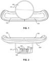
- FIG. 1 depicts a bottom view of the controller add-on device.
- the controller add-on device comprises a housing 101 which is configured to couple to mechanically connect to the body of a controller.
- the housing also serves as a rigid attachment point for a plurality of buttons. Shown in FIG. 1 the add-on device comprises a right customizable button 102 and a left customizable button 103 but the scope of the present disclosure is not so limited.
- the plurality buttons 102, 103 are configured to be within reach of a user's index, middle or ring fingers while holding the body of the game controller.
- a portion of the housing 101 that includes the customizable buttons 102, 103 may be coupled to the housing by way of a hinged controller interface 201, seen in FIG. 2 .
- the customizable buttons may be mechanically connected to the housing by way of attachment to a switch mounted to a printed circuit board, the printed circuit board coupled to the housing by, e.g., screws, pins, glue, plastic hot-stakes, clips, or housing elements.
- the controller add-on may have a display screen 105.
- the display screen 105 may be coupled to the housing by way of rigid attachment means.
- the display screen may be associated with, e.g., mechanically incorporated into, an input interface, e.g., a mechanical button.
- the display screen may include user interface elements as touch screen, such as a capacitive touch screen or a resistive touch screen.
- touch screen such as a capacitive touch screen or a resistive touch screen.
- the input interface may be configured to be within reach of a user's index, middle or ring fingers while holding the body of the game controller. In some implementations, the input interface and/or buttons may be within reach of the user's thumbs, as well.
- display screen may be replaced by other communication elements such as a speaker connected to a printed circuit board attached to the housing by rigid attachment means.
- the user interface may feature a plurality of lights.
- the user interface may comprise both a display screen and a speaker.
- the display screen is connected to a printed circuit board attached to the housing by rigid attachment means.
- the speaker is attached to the housing by rigid attachment means.
- FIG. 2 depicts a front view of the controller add-on device.
- the housing 101 provides a cavity, which is configured to fit a controller body.
- a controller interface mount 201 is coupled to the housing 101.
- the controller interface mount 201 may be rotatably coupled to the housing 101, e.g., by a hinge 104.
- the controller interface mount 201 comprises one or more controller interfaces, e.g., an analog interface 202 and a digital interface 203. These one or more controller interfaces are configured to communicatively couple the plurality of buttons 102, 103 to the controller.
- the controller interface mount 201 is configured to tilt with from a first position in which the add-on device can make a physical and mechanical connection with the body of the game controller to a second position in which a portion of the housing 101 conformally contacts the body of a game controller.
- the one or more controller interfaces may include, e.g., Serial connectors, Universal Serial Bus interfaces (USB), co-axialjack (co-ax), audio jack, S/PDIF connector, parallel connector and the like.
- the housing may also have a conformal surface 204 located opposite the surface having the buttons 102,103.
- the conformal surface 204 is configured to make conformal contact with a controller body.
- the conformal surface may include a pliable material to dampen vibration from button presses as well as to provide a solid contact surface with the controller body.
- the pliable material may be any suitable material such as rubber, silicone, soft plastic, leather, and the like.
- FIG. 3 depicts a side view of the controller add-on device.
- the one or more controller interfaces 202, 203 extend outward from the housing 101.
- the housing has a curved portion 301 to better conform to the shape of the controller when mounted.
- the curved portion 301 in conjunction with the tilting interface mount 201 also allows the controller add-on devices to be placed in a first position to make physical and mechanical connection with the body of the controller, e.g., as depicted in FIG. 6 , and then tilted to a second position to make conformal contact with the body of the game controller, as depicted, e.g., in FIG. 8 .
- the curved arrow in FIG. 3 indicates the direction of tilt of the interface mount 201 to go from the second position to the first position.
- FIG 4 depicts a back view of the controller add-on device.
- This view shows an (optional) communication interface port 401.
- This communication interface port 401 may be used to relay signals from the controller to additional devices such as headphones or other user interfaces.
- the communication interface port may also receive signals from devices such as microphones or other user interfaces and relay those signals back to the controller.
- the communication interface port 401 may be of a similar type as the one or more communication interfaces 202, 203.
- one or more communication interfaces 202, 203 may be coupled to the housing 101 so that the communication interfaces extend outward from the housing over the conformal surface 204.
- FIG. 6 depicts a side view of the orientation of the controller add-on device when initially coupled with a controller 501 (indicated by dashed lines).
- the tilting interface mount 201 allows the housing 101 to be tilted downward relative to the controller 501 when the analog interface 202 and the digital interface 203 connects to corresponding interfaces 504 on the controller.
- the housing 101 is configured to fit securely between the two handholds 502 of the controller and not interfere with the joysticks 503.
- the tilting interface mount 201 allows the housing 101 to tilt upward toward the controller 501 in the direction indicated by the arrow so that the conformal surface 204 opposite the plurality of buttons 102, 103 can make conformal contact with the bottom of the controller.
- the curved arrow in the three-dimensional diagram of a controller add-on device shown in FIG. 7 indicates the direction of relative movement of the tilting interface mount 201 as the device rotates from the first position in which connection is made to the controller to the second position in which the conformal surface 204 conforms to the bottom of the controller.
- FIG. 8 depicts a bottom view of the controller add-on device when coupled with a controller in the operational position.
- the controller add-on device is positioned between the two handholds of the controllers and the plurality of buttons 102, 103 on the controller add-on device are configured to be within reach of a user's index, middle or ring fingers while holding the body of the game controller.
- the housing 101 is configured to fit on a side of the controller body opposite the two joysticks 503 so that operation of the buttons does not affect operation of the joysticks.
- the display screen 105 may be configured to face downward and be easily viewed when the controller body 503 is turned upside down.
- the display screen has an associated input device, e.g., a button or touch interface that can be operated by the user.
- an associated input device e.g., a button or touch interface that can be operated by the user.
- the depicted embodiment shows a display screen 105 mounted in the downward position when the controller add-on device is couple to the controller body 503, the scope of this disclosure is not so limited. In other embodiments, the display screen may be configured face upward or frontward while the controller add-on device is coupled to the controller body.
- the flow diagram of FIG. 9 illustrates a method for pre-set generation with a controller add-on device according to aspects of the present disclosure.
- the method begins when a pre-set customization entry mode input is received, as indicated at 901.
- the pre-set customization entry mode input may be a button press, a combination of button press or a selection using a touch screen.
- the pre-set customization entry mode allows users to map the plurality of buttons of the controller add-on to the buttons or inputs of the controller.
- the pre-set customization mode allows button mappings to be saved as pre-sets and creates the ability for the user to easily switch between pre-sets when the controller add-on device is not in pre-set customization entry mode.
- the controller add-on device Upon receiving pre-set customization entry, mode input the controller add-on device enters the pre-set customization entry mode 902.
- the user may begin mapping keys by selecting a controller button and choosing a button of the plurality buttons 102, 103 of the controller add-on to represent that controller button and provide that button's input when pressed.
- the controller add-on device receives this mapping from the user, as indicated at 903.
- the mapping may be performed using a user interface such as an input device incorporated into the display screen 105 or may be performed using a separate program running on a host device such as a game console or a computer.
- the button mapping may be created, as a pre-set in a list of pre-set, each pre-set in the list of pre-set may be blank before the user creates a button mapping or may be set to a default button mapping that can be change easily by the user.
- new button mapping preset may be created by the user and added to a list of pre-sets that may unpopulated.
- the user may select to exit the pre-set customization entry mode.
- the user may take the necessary action to exit the pre-set customization mode, this action is received by the controller add-on device and subsequently the controller add-on device exits the pre-set customization entry mode 904.
- the user may exit the pre-set customization mode by pressing an exit button or entering series of button presses or selecting an option within a user interface.
- the user may exit the pre-set customization mode by refraining from pressing a button for a period.
- the exit button may be implemented using an input device, e.g., touch interface or mechanical button associated with the display screen 105.
- the controller add-on device After exiting the pre-set customization entry mode, the controller add-on device saves the pre-set or presets entered by the user 905.
- the pre-set or pre-sets entered by the user may be saved to a list of pre-sets stored in the memory of the controller add-on device.
- a very useful feature of the present disclosure is that after the pre-set entered by the user to the list of pre-sets the device may hide or otherwise makes un-selectable pre-sets that are empty, invalid or chosen to be hidden 906. This allows users to quickly switch between valid pre-sets during operation of the controller add-on device, e.g., using a button or touch interface that can be operated by the user. This mode of operation can be advantageous if the display screen and associated input device face away from the user during operation. Reducing the available modes to a relatively small number, e.g., two, makes it easy for the user to toggle between them without having to look at the screen.
- FIG. 10 depicts the method for switching between pre-sets according to aspects of the present disclosure.
- add-on device the user may desire to switch between two or more different presets on the preset list. To do this the user may press a button or a series of button, or make a selection using a touch screen.
- the controller add-on device receives the pre-set change input from the user 1001. Subsequently the controller add-on device selects the next pre-set in the pre-set list and applies that configuration to the plurality buttons 1002.
- a feature of the present disclosure is where, the next pre-set in the pre-set list is blank, invalid or otherwise hidden, the controller add-on device will skip that pre-set in the list and select the next pre-set instead.
- the user interface of the controller add-on device will display the selected pre-set 1003.
- press by the user on one of the plurality of button 1004 triggers the pre-set button mapping.
- the pre-set button mapping sends a signal corresponding to the signal of the mapped button in the selected pre-set to the controller 1005. This signal is received by the controller, which interprets the signal as a button press for the mapped button.
- a pre-set button mapping may map an X-button of a game pad controller to the left button 102 and a O-button to the right button 103 of the controller add-on.
- the device sends a signal to the controller that the X-button has been pressed.
- the controller interprets this signal as though the X-button on the game pad controller has been pressed and communicates the X-button press signal to the game console.
- two objects, devices, or systems are "communicatively coupled" when information can be transmitted from one object to a second object by way of some form of signal.
- the signal may be an electric signal delivered through an electrically conductive interface, a mechanical signal delivered through a mechanical interface, an acoustic signal delivered through a sound-transmitting medium, or an electromagnetic signal such as a radio signal, microwave signal or a light signal, which may be delivered through a medium, such as a fiber-optic medium, a waveguide, or through free space.
- Communicative coupling encompasses the use of intermediary objects, devices, and systems such as transducers, transmitters, amplifiers, receivers, and signal processers, e.g., digital signal processers.
- Communicative coupling is a distinct concept from mechanical connection, though the two concepts are not mutually exclusive.
- communicative coupling via mechanical interface between two objects be distinguished from mechanical connection of the two objects.
- an actuating stud on one component may press a button on a second object when the two objects are connected by means of screws.
- the stud-button interaction provides mechanical communicative coupling, while the screws provide mechanical connection.
- a system 1100 may include a processor 1101 and a memory 1102 (e.g., RAM, DRAM, ROM, and the like). In addition, the system 1100 may have multiple processors 1101 if parallel processing is to be implemented.
- the memory 1102 includes data 1106 and game program code 1104, which may include portions that are configured as described above. Specifically, the memory 1102 may include button mapping pre-set data 1106, which may include a stored pre-set list.
- the memory 1102 may also contain programs for switching pre-sets and programs for pre-set creation 1104.
- the system 1100 may also include well-known support functions 1110, such as input/output (I/O) elements 1111, power supplies (P/S) 1112, a clock (CLK) 1113 and cache 1114.
- the apparatus 1100 may optionally include a mass storage device 1115 such as a disk drive, CD-ROM drive, tape drive, or the like to store programs and/or data.
- the controller may also optionally include a display unit 1116 and user interface unit 1118 to facilitate interaction between the controller 1100 and a user.
- the display unit 1116 may be in the form of a cathode ray tube (CRT) or flat panel screen that displays text, numerals, graphical symbols or images.
- the user interface 1118 may include a keyboard, mouse, joystick, light pen or other device.
- the user interface 1118 may include a microphone, video camera or other signal-transducing device to provide for direct capture of a signal to be analyzed.
- the processor 1101, memory 1102 and other components of the system 1100 may exchange signals (e.g., code instructions and data) with each other via a system bus 1120.
- a microphone array 1122 may be coupled to the system 1100 through the I/O functions 1111.
- An optional image capture unit 1123 e.g., a digital camera
- One or more pointing actuators 1125 that are mechanically coupled to the camera may exchange signals with the processor 1101 via the I/O functions 1111.
- I/O generally refers to any program, operation or device that transfers data to or from the system 1100 and to or from a peripheral device. Every data transfer may be regarded as an output from one device and an input into another.
- Peripheral devices include input-only devices, such as keyboards and mice, output-only devices, such as printers as well as devices such as a writable CD-ROM that can act as both an input and an output device.
- peripheral device includes external devices, such as a mouse, keyboard, printer, monitor, microphone, game controller, camera, external Zip drive or scanner as well as internal devices, such as a solid state drive (SSD), CD-ROM drive, CD-R drive or internal modem or other peripheral such as a flash memory reader/writer, hard drive.
- external devices such as a mouse, keyboard, printer, monitor, microphone, game controller, camera, external Zip drive or scanner
- internal devices such as a solid state drive (SSD), CD-ROM drive, CD-R drive or internal modem or other peripheral such as a flash memory reader/writer, hard drive.
- the system 1100 may be a video game unit, which may include a controller 1130 coupled to the processor via the I/O functions 1111 either through wires (e.g., a USB cable) or wirelessly. Additionally in other embodiments, the system 1100 may be a computer system with a peripheral controller 1130.
- the controller 1130 may have analog joystick controls 1131 and conventional buttons 1133 that provide control signals commonly used during playing of video games.
- Such video games may be implemented as processor readable data and/or instructions from the program 1104, which may be stored in the memory 1102, or other processor readable medium such as one associated with the mass storage device 1115.
- the controller 1130 may include one or more inertial sensors 1132, which may provide position and/or orientation information to the processor 1101 via an inertial signal. Orientation information may include angular information such as a tilt, roll or yaw of the controller 1130.
- the inertial sensors 1132 may include any number and/or combination of accelerometers, gyroscopes or tilt sensors.
- the joystick controller 1130 may include one or more light sources 1134, such as light emitting diodes (LEDs). The light sources 1134 may be used to distinguish one controller from the other.
- LEDs light emitting diodes
- the processor 1101 may use inertial signals from the inertial sensors 1132 in conjunction with optical signals from light sources 1134 detected by an image capture unit to deduce information on the location and/or orientation of the controller 1130 and/or its user.
- the controller add-on device 1140 couples to the controller 1130 through an interface port on the controller (not shown).
- the controller add-on device may communicate with the controller 1130 and the game console 1100 through I/O functions 1141, which are coupled to the communication interface.
- the controller add-on device may comprise a processor 1142 and memory 1143 as well as a display 1144 and a user interface 1145.
- the user interface may comprise a plurality buttons for example a left button a right button and a touch screen or mechanical button associated therewith.
- the memory 1143 may contain programs 1146 which when carried out by the processor 1142 cause the controller add-on device to enact methods for entering a button mapping pre-set 1147, e.g., as shown FIG 9 or the method for switching button mapping pre-sets, e.g., as shown in FIG 10 .
- the programs 1146 may also enact a button-mapping scheme for the plurality of buttons in the user interface 1145.
- the I/O functions 1141 may contain various connectors and ports to connect the controller add-on device 1140 to the controller and communicate with the controller 1130 and the system 1100.
- the I/O 1140 for example and without limitation may comprise a 3.5mm audio jack, a serial connector, and a 3.5mm audio port.
- I/O may pass audio signals from the 3.5mm audio through to the 3.5mm audio port.
- the controller add-on device also comprises a serial port and the I/O functions to receive signals from the serial port and pass the signals through to the game controller.
Landscapes
- Engineering & Computer Science (AREA)
- Multimedia (AREA)
- Human Computer Interaction (AREA)
- Computer Hardware Design (AREA)
- Theoretical Computer Science (AREA)
- General Physics & Mathematics (AREA)
- General Engineering & Computer Science (AREA)
- Physics & Mathematics (AREA)
- User Interface Of Digital Computer (AREA)
- Input From Keyboards Or The Like (AREA)
- Position Input By Displaying (AREA)
- Photoreceptors In Electrophotography (AREA)
- Epoxy Resins (AREA)
- Electrophonic Musical Instruments (AREA)
Description
- Aspects of the present disclosure are related to game controllers. Specifically aspects of the present disclosure are related to game controller add-ons.
- Previously proposed arrangements are disclosed in
US 2005/233808 A1 ,US 2004/224765 A1 andUS 2017/354895 A1 . Current game controllers have many buttons that are assigned functions by an application running on a computer or a video game console. Additionally, current game controllers have multiple types of buttons that operate in various different ways to better match the role to which they are assigned by the application. For example, a controller may have joysticks, a directional pad (d-pad), shoulder buttons, touch screens, and action buttons. Despite a heavy emphasis on ergonomic design, a number of buttons on the game controller may be out of reach for the average hand while using certain functions. - Thus, there is a need in the art, for a way to add more buttons to a game controller that are within the reach of the user while using certain functions.
- The invention is defined by the appended claims.
- The teachings of the present disclosure can be readily understood by considering the following detailed description in conjunction with the accompanying drawings, in which:
-
FIG. 1 is a bottom view diagram of a controller add-on device according to an aspect of the present disclosure. -
FIG. 2 is a front view diagram of a controller add-on device according to an aspect of the present disclosure. -
FIG. 3 is a right side view diagram of a controller add-on device according to an aspect of the present disclosure. -
FIG. 4 is a top view diagram of a controller add-on device according to an aspect of the present disclosure. -
FIG. 5 is a back view diagram of a controller add-on device according to an aspect of the present disclosure. -
FIG. 6 is a left side view diagram of a controller add-on device mounted to a controller according to an aspect of the present disclosure. -
FIG. 7 is a three-dimensional diagram of a controller add-on device according to an aspect of the present disclosure. -
FIG. 8 is a bottom view diagram of a controller add-on device mounted to a controller according to an aspect of the present disclosure. -
FIG. 9 is a block diagram of a method for entering button mapping presets according to an aspect of the present disclosure. -
FIG. 10 is a block diagram of a method for switching mapped button presets according to an aspect of the present disclosure. -
FIG. 11 is a block system diagram of a controller add-on device connected to a computing system according to an aspect of the present disclosure. - Although the following detailed description contains many specific details for the purposes of illustration, anyone of ordinary skill in the art will appreciate that many variations and alterations to the following details are within the scope of the invention. Accordingly, the exemplary embodiments of the invention described below are set forth without any loss of generality to, and without imposing limitations upon, the claimed invention.
- In the following Detailed Description, reference is made to the accompanying drawings, which form a part hereof, and in which is shown by way of illustration specific embodiments in which the invention may be practiced. In this regard, directional terminology, such as "top," "bottom," "front," "back," "leading," "trailing," etc., is used with reference to the orientation of the figure(s) being described. Because components of embodiments of the present invention can be positioned in a number of different orientations, the directional terminology is used for purposes of illustration and is in no way limiting. It is to be understood that other embodiments may be utilized and structural or logical changes may be made without departing from the scope of the present invention. The following detailed description, therefore, is not to be taken in a limiting sense, and the scope of the present invention is defined by the appended claims.
- The present disclosure describes a controller add-on device configured to add additional customizable buttons to a controller.
FIG. 1 depicts a bottom view of the controller add-on device. The controller add-on device comprises ahousing 101 which is configured to couple to mechanically connect to the body of a controller. The housing also serves as a rigid attachment point for a plurality of buttons. Shown inFIG. 1 the add-on device comprises a rightcustomizable button 102 and a leftcustomizable button 103 but the scope of the present disclosure is not so limited. Theplurality buttons - In some embodiments a portion of the
housing 101 that includes thecustomizable buttons controller interface 201, seen inFIG. 2 . Alternatively, the customizable buttons may be mechanically connected to the housing by way of attachment to a switch mounted to a printed circuit board, the printed circuit board coupled to the housing by, e.g., screws, pins, glue, plastic hot-stakes, clips, or housing elements. In some embodiments, the controller add-on may have adisplay screen 105. Thedisplay screen 105 may be coupled to the housing by way of rigid attachment means. The display screen may be associated with, e.g., mechanically incorporated into, an input interface, e.g., a mechanical button. Additionally the display screen may include user interface elements as touch screen, such as a capacitive touch screen or a resistive touch screen. In implementations where add-on includes thedisplay screen 105 and the buttons 102,103, the input interface may be configured to be within reach of a user's index, middle or ring fingers while holding the body of the game controller. In some implementations, the input interface and/or buttons may be within reach of the user's thumbs, as well. - In other embodiments, display screen may be replaced by other communication elements such as a speaker connected to a printed circuit board attached to the housing by rigid attachment means. In alternative embodiments the user interface may feature a plurality of lights. In additional embodiments the user interface may comprise both a display screen and a speaker. In some embodiments the display screen is connected to a printed circuit board attached to the housing by rigid attachment means. In other additional embodiments the speaker is attached to the housing by rigid attachment means.
-
FIG. 2 depicts a front view of the controller add-on device. As shown thehousing 101 provides a cavity, which is configured to fit a controller body. Acontroller interface mount 201 is coupled to thehousing 101. Thecontroller interface mount 201 may be rotatably coupled to thehousing 101, e.g., by ahinge 104. Thecontroller interface mount 201 comprises one or more controller interfaces, e.g., ananalog interface 202 and adigital interface 203. These one or more controller interfaces are configured to communicatively couple the plurality ofbuttons controller interface mount 201 is configured to tilt with from a first position in which the add-on device can make a physical and mechanical connection with the body of the game controller to a second position in which a portion of thehousing 101 conformally contacts the body of a game controller. The one or more controller interfaces may include, e.g., Serial connectors, Universal Serial Bus interfaces (USB), co-axialjack (co-ax), audio jack, S/PDIF connector, parallel connector and the like. The housing may also have aconformal surface 204 located opposite the surface having the buttons 102,103. Theconformal surface 204 is configured to make conformal contact with a controller body. The conformal surface may include a pliable material to dampen vibration from button presses as well as to provide a solid contact surface with the controller body. The pliable material may be any suitable material such as rubber, silicone, soft plastic, leather, and the like. -
FIG. 3 depicts a side view of the controller add-on device. As can be seen, the one ormore controller interfaces housing 101. The housing has acurved portion 301 to better conform to the shape of the controller when mounted. Thecurved portion 301 in conjunction with the tiltinginterface mount 201 also allows the controller add-on devices to be placed in a first position to make physical and mechanical connection with the body of the controller, e.g., as depicted inFIG. 6 , and then tilted to a second position to make conformal contact with the body of the game controller, as depicted, e.g., inFIG. 8 . The curved arrow inFIG. 3 indicates the direction of tilt of theinterface mount 201 to go from the second position to the first position. -
FIG 4 depicts a back view of the controller add-on device. This view shows an (optional)communication interface port 401. Thiscommunication interface port 401 may be used to relay signals from the controller to additional devices such as headphones or other user interfaces. The communication interface port may also receive signals from devices such as microphones or other user interfaces and relay those signals back to the controller. Thecommunication interface port 401 may be of a similar type as the one ormore communication interfaces - As seen in the top-down view of the controller add-on device in
FIG. 5 , one ormore communication interfaces housing 101 so that the communication interfaces extend outward from the housing over theconformal surface 204. -
FIG. 6 depicts a side view of the orientation of the controller add-on device when initially coupled with a controller 501 (indicated by dashed lines). As shown, the tiltinginterface mount 201 allows thehousing 101 to be tilted downward relative to thecontroller 501 when theanalog interface 202 and thedigital interface 203 connects tocorresponding interfaces 504 on the controller. In the depicted implementation, thehousing 101 is configured to fit securely between the twohandholds 502 of the controller and not interfere with thejoysticks 503. After connection is made, the tiltinginterface mount 201 allows thehousing 101 to tilt upward toward thecontroller 501 in the direction indicated by the arrow so that theconformal surface 204 opposite the plurality ofbuttons FIG. 7 indicates the direction of relative movement of the tiltinginterface mount 201 as the device rotates from the first position in which connection is made to the controller to the second position in which theconformal surface 204 conforms to the bottom of the controller. -
FIG. 8 depicts a bottom view of the controller add-on device when coupled with a controller in the operational position. As shown, the controller add-on device is positioned between the two handholds of the controllers and the plurality ofbuttons housing 101 is configured to fit on a side of the controller body opposite the twojoysticks 503 so that operation of the buttons does not affect operation of the joysticks. Thedisplay screen 105 may be configured to face downward and be easily viewed when thecontroller body 503 is turned upside down. This can be advantageous when the display screen has an associated input device, e.g., a button or touch interface that can be operated by the user. While the depicted embodiment shows adisplay screen 105 mounted in the downward position when the controller add-on device is couple to thecontroller body 503, the scope of this disclosure is not so limited. In other embodiments, the display screen may be configured face upward or frontward while the controller add-on device is coupled to the controller body. - The flow diagram of
FIG. 9 illustrates a method for pre-set generation with a controller add-on device according to aspects of the present disclosure. The method begins when a pre-set customization entry mode input is received, as indicated at 901. The pre-set customization entry mode input may be a button press, a combination of button press or a selection using a touch screen. The pre-set customization entry mode allows users to map the plurality of buttons of the controller add-on to the buttons or inputs of the controller. The pre-set customization mode allows button mappings to be saved as pre-sets and creates the ability for the user to easily switch between pre-sets when the controller add-on device is not in pre-set customization entry mode. Upon receiving pre-set customization entry, mode input the controller add-on device enters the pre-setcustomization entry mode 902. The user may begin mapping keys by selecting a controller button and choosing a button of theplurality buttons display screen 105 or may be performed using a separate program running on a host device such as a game console or a computer. The button mapping may be created, as a pre-set in a list of pre-set, each pre-set in the list of pre-set may be blank before the user creates a button mapping or may be set to a default button mapping that can be change easily by the user. Alternatively, new button mapping preset may be created by the user and added to a list of pre-sets that may unpopulated. - Upon creation of a button mapping pre-set the user may select to exit the pre-set customization entry mode. The user may take the necessary action to exit the pre-set customization mode, this action is received by the controller add-on device and subsequently the controller add-on device exits the pre-set
customization entry mode 904. According to aspects of the present disclosure, the user may exit the pre-set customization mode by pressing an exit button or entering series of button presses or selecting an option within a user interface. Alternatively, the user may exit the pre-set customization mode by refraining from pressing a button for a period. In some implementations, the exit button may be implemented using an input device, e.g., touch interface or mechanical button associated with thedisplay screen 105. - After exiting the pre-set customization entry mode, the controller add-on device saves the pre-set or presets entered by the
user 905. The pre-set or pre-sets entered by the user may be saved to a list of pre-sets stored in the memory of the controller add-on device. A very useful feature of the present disclosure is that after the pre-set entered by the user to the list of pre-sets the device may hide or otherwise makes un-selectable pre-sets that are empty, invalid or chosen to be hidden 906. This allows users to quickly switch between valid pre-sets during operation of the controller add-on device, e.g., using a button or touch interface that can be operated by the user. This mode of operation can be advantageous if the display screen and associated input device face away from the user during operation. Reducing the available modes to a relatively small number, e.g., two, makes it easy for the user to toggle between them without having to look at the screen. -
FIG. 10 depicts the method for switching between pre-sets according to aspects of the present disclosure. During operation of the controller, add-on device the user may desire to switch between two or more different presets on the preset list. To do this the user may press a button or a series of button, or make a selection using a touch screen. The controller add-on device receives the pre-set change input from theuser 1001. Subsequently the controller add-on device selects the next pre-set in the pre-set list and applies that configuration to theplurality buttons 1002. A feature of the present disclosure is where, the next pre-set in the pre-set list is blank, invalid or otherwise hidden, the controller add-on device will skip that pre-set in the list and select the next pre-set instead. Additionally the user interface of the controller add-on device will display the selectedpre-set 1003. After selection of a button mapping pre-set a button, press by the user on one of the plurality ofbutton 1004 triggers the pre-set button mapping. The pre-set button mapping sends a signal corresponding to the signal of the mapped button in the selected pre-set to thecontroller 1005. This signal is received by the controller, which interprets the signal as a button press for the mapped button. - By way of example and not by way limitation a pre-set button mapping may map an X-button of a game pad controller to the
left button 102 and a O-button to theright button 103 of the controller add-on. When a user presses theleft button 102 of the controller add-on device, the device sends a signal to the controller that the X-button has been pressed. The controller interprets this signal as though the X-button on the game pad controller has been pressed and communicates the X-button press signal to the game console. - As used herein, two objects, devices, or systems are "communicatively coupled" when information can be transmitted from one object to a second object by way of some form of signal. By way of example the signal may be an electric signal delivered through an electrically conductive interface, a mechanical signal delivered through a mechanical interface, an acoustic signal delivered through a sound-transmitting medium, or an electromagnetic signal such as a radio signal, microwave signal or a light signal, which may be delivered through a medium, such as a fiber-optic medium, a waveguide, or through free space. Communicative coupling encompasses the use of intermediary objects, devices, and systems such as transducers, transmitters, amplifiers, receivers, and signal processers, e.g., digital signal processers.
- Communicative coupling is a distinct concept from mechanical connection, though the two concepts are not mutually exclusive. As a non-limiting example, communicative coupling via mechanical interface between two objects be distinguished from mechanical connection of the two objects. For example, an actuating stud on one component may press a button on a second object when the two objects are connected by means of screws. The stud-button interaction provides mechanical communicative coupling, while the screws provide mechanical connection.
- According to embodiments of the present invention, a system with a controller having a controller add-on device and method of the type described above may be implemented as depicted in
FIG. 11 . Asystem 1100 may include a processor 1101 and a memory 1102 (e.g., RAM, DRAM, ROM, and the like). In addition, thesystem 1100 may have multiple processors 1101 if parallel processing is to be implemented. Thememory 1102 includesdata 1106 andgame program code 1104, which may include portions that are configured as described above. Specifically, thememory 1102 may include buttonmapping pre-set data 1106, which may include a stored pre-set list. Thememory 1102 may also contain programs for switching pre-sets and programs forpre-set creation 1104. - The
system 1100 may also include well-known support functions 1110, such as input/output (I/O)elements 1111, power supplies (P/S) 1112, a clock (CLK) 1113 andcache 1114. Theapparatus 1100 may optionally include amass storage device 1115 such as a disk drive, CD-ROM drive, tape drive, or the like to store programs and/or data. The controller may also optionally include adisplay unit 1116 and user interface unit 1118 to facilitate interaction between thecontroller 1100 and a user. Thedisplay unit 1116 may be in the form of a cathode ray tube (CRT) or flat panel screen that displays text, numerals, graphical symbols or images. The user interface 1118 may include a keyboard, mouse, joystick, light pen or other device. In addition, the user interface 1118 may include a microphone, video camera or other signal-transducing device to provide for direct capture of a signal to be analyzed. The processor 1101,memory 1102 and other components of thesystem 1100 may exchange signals (e.g., code instructions and data) with each other via asystem bus 1120. - A microphone array 1122 may be coupled to the
system 1100 through the I/O functions 1111. An optional image capture unit 1123 (e.g., a digital camera) may be coupled to theapparatus 1100 through the I/O functions 1111. One or more pointing actuators 1125 that are mechanically coupled to the camera may exchange signals with the processor 1101 via the I/O functions 1111. - As used herein, the term I/O generally refers to any program, operation or device that transfers data to or from the
system 1100 and to or from a peripheral device. Every data transfer may be regarded as an output from one device and an input into another. Peripheral devices include input-only devices, such as keyboards and mice, output-only devices, such as printers as well as devices such as a writable CD-ROM that can act as both an input and an output device. The term "peripheral device" includes external devices, such as a mouse, keyboard, printer, monitor, microphone, game controller, camera, external Zip drive or scanner as well as internal devices, such as a solid state drive (SSD), CD-ROM drive, CD-R drive or internal modem or other peripheral such as a flash memory reader/writer, hard drive. - In certain embodiments of the invention, the
system 1100 may be a video game unit, which may include acontroller 1130 coupled to the processor via the I/O functions 1111 either through wires (e.g., a USB cable) or wirelessly. Additionally in other embodiments, thesystem 1100 may be a computer system with aperipheral controller 1130. Thecontroller 1130 may have analog joystick controls 1131 andconventional buttons 1133 that provide control signals commonly used during playing of video games. Such video games may be implemented as processor readable data and/or instructions from theprogram 1104, which may be stored in thememory 1102, or other processor readable medium such as one associated with themass storage device 1115. - The
controller 1130 may include one or more inertial sensors 1132, which may provide position and/or orientation information to the processor 1101 via an inertial signal. Orientation information may include angular information such as a tilt, roll or yaw of thecontroller 1130. By way of example, the inertial sensors 1132 may include any number and/or combination of accelerometers, gyroscopes or tilt sensors. In addition, thejoystick controller 1130 may include one or morelight sources 1134, such as light emitting diodes (LEDs). Thelight sources 1134 may be used to distinguish one controller from the other. - The processor 1101 may use inertial signals from the inertial sensors 1132 in conjunction with optical signals from
light sources 1134 detected by an image capture unit to deduce information on the location and/or orientation of thecontroller 1130 and/or its user. - The controller add-on device 1140 couples to the
controller 1130 through an interface port on the controller (not shown). The controller add-on device may communicate with thecontroller 1130 and thegame console 1100 through I/O functions 1141, which are coupled to the communication interface. The controller add-on device may comprise aprocessor 1142 andmemory 1143 as well as a display 1144 and a user interface 1145. The user interface may comprise a plurality buttons for example a left button a right button and a touch screen or mechanical button associated therewith. Thememory 1143 may containprograms 1146 which when carried out by theprocessor 1142 cause the controller add-on device to enact methods for entering abutton mapping pre-set 1147, e.g., as shownFIG 9 or the method for switching button mapping pre-sets, e.g., as shown inFIG 10 . Theprograms 1146 may also enact a button-mapping scheme for the plurality of buttons in the user interface 1145. The I/O functions 1141 may contain various connectors and ports to connect the controller add-on device 1140 to the controller and communicate with thecontroller 1130 and thesystem 1100. The I/O 1140 for example and without limitation may comprise a 3.5mm audio jack, a serial connector, and a 3.5mm audio port. In some embodiments and without limitation I/O may pass audio signals from the 3.5mm audio through to the 3.5mm audio port. Additionally in some embodiments, the controller add-on device also comprises a serial port and the I/O functions to receive signals from the serial port and pass the signals through to the game controller.
Claims (7)
- A controller add-on comprising:a housing (101), wherein the housing is configured to mechanically couple to a body of a game controller (501), wherein a conformable surface of the housing is configured to conform with a bottom of the body of the game controller;a plurality of buttons (102, 103) coupled to the housing wherein the plurality of buttons are located opposite the conformable surface; anda controller interface (201, 202, 203) coupled to the housing wherein the controller interface is configured to communicatively couple the plurality of buttons to the game controller, wherein the controller interface is further configured to tilt from a first position to make a physical and mechanical connection with the body of the game controller to a second position wherein the conformable surface contacts to the bottom of the body of game controller.
- The controller add-on of claim 1, further comprising a display screen (105) coupled to the housing.
- The controller add-on of claim 2, further comprising an input interface associated with the display screen.
- The controller add-on of claim 3, wherein the input interface is a touch interface.
- The controller add-on of claim 3, wherein the input interface is a mechanical button.
- The controller add-on of claim 1, wherein the plurality of buttons are configured to be within reach of a user's index, middle or ring fingers while holding the body of the game controller.
- The controller add-on of claim 1, further comprising a display screen (105) coupled to the housing and an input interface associated with the display screen, wherein the plurality of buttons and the input interface are configured to be within reach of a user's index, middle or ring fingers while holding the body of the game controller.
Applications Claiming Priority (2)
| Application Number | Priority Date | Filing Date | Title |
|---|---|---|---|
| US16/526,238 US10940385B2 (en) | 2019-07-30 | 2019-07-30 | Controller add-on device with customizable presets |
| PCT/US2020/040181 WO2021021362A1 (en) | 2019-07-30 | 2020-06-29 | Controller add-on device with customizable presets |
Publications (3)
| Publication Number | Publication Date |
|---|---|
| EP4003556A1 EP4003556A1 (en) | 2022-06-01 |
| EP4003556A4 EP4003556A4 (en) | 2023-07-26 |
| EP4003556B1 true EP4003556B1 (en) | 2024-09-11 |
Family
ID=74230783
Family Applications (1)
| Application Number | Title | Priority Date | Filing Date |
|---|---|---|---|
| EP20847456.9A Active EP4003556B1 (en) | 2019-07-30 | 2020-06-29 | Controller add-on device with customizable presets |
Country Status (6)
| Country | Link |
|---|---|
| US (1) | US10940385B2 (en) |
| EP (1) | EP4003556B1 (en) |
| JP (1) | JP7133742B2 (en) |
| CN (1) | CN114206452B (en) |
| TW (1) | TWI787616B (en) |
| WO (1) | WO2021021362A1 (en) |
Families Citing this family (6)
| Publication number | Priority date | Publication date | Assignee | Title |
|---|---|---|---|---|
| US12194375B2 (en) | 2017-01-25 | 2025-01-14 | Kieran S. Lyden | Game controller |
| USD934345S1 (en) * | 2019-07-30 | 2021-10-26 | Sony Interactive Entertainment Inc. | Controller add-on device |
| USD1020897S1 (en) * | 2021-04-25 | 2024-04-02 | Jiarui Zhu | Keypad for game controller |
| US12109486B2 (en) * | 2021-11-09 | 2024-10-08 | Sony Interactive Entertainment Inc. | Computer simulation controller |
| EP4571474A1 (en) * | 2022-08-10 | 2025-06-18 | Sony Interactive Entertainment Inc. | Information processing device, information processing system, and computer program |
| WO2024236676A1 (en) * | 2023-05-15 | 2024-11-21 | 株式会社ソニー・インタラクティブエンタテインメント | Information processing device, information processing system, information processing method, and computer program |
Family Cites Families (35)
| Publication number | Priority date | Publication date | Assignee | Title |
|---|---|---|---|---|
| US744044A (en) | 1903-09-03 | 1903-11-17 | Edward Burnham | Hair-drying device. |
| CN1177634C (en) * | 1996-03-05 | 2004-12-01 | 世嘉企业股份有限公司 | Controllers and Electronics |
| USD441404S1 (en) | 2000-02-17 | 2001-05-01 | Ascii Corporation | Controller for video games |
| USD441405S1 (en) | 2000-02-17 | 2001-05-01 | Ascii Corporation | Controller for video games |
| US6773349B2 (en) * | 2002-07-31 | 2004-08-10 | Intec, Inc. | Video game controller with integrated video display |
| US20040033835A1 (en) * | 2002-08-14 | 2004-02-19 | Chao Chang Chih | Device for illuminating palm-top TV game |
| US7283125B2 (en) | 2003-05-09 | 2007-10-16 | Microsoft Corporation | Text input device and adapter mechanism |
| JP3734815B2 (en) * | 2003-12-10 | 2006-01-11 | 任天堂株式会社 | Portable game device and game program |
| US8241126B2 (en) | 2009-11-04 | 2012-08-14 | Valve Corporation | Video game controller having user swappable control components |
| USD635615S1 (en) | 2009-12-01 | 2011-04-05 | Activision Publishing, Inc. | Board peripheral for video game |
| USD645910S1 (en) | 2009-12-01 | 2011-09-27 | Activision Publishing, Inc. | Board peripheral for video game |
| CN102274635A (en) * | 2011-07-30 | 2011-12-14 | 周海涛 | Game controller |
| US9445392B1 (en) | 2011-10-07 | 2016-09-13 | BlueStack Systems, Inc. | Method of providing non-native notifications and system thereof |
| US20140139455A1 (en) * | 2012-09-18 | 2014-05-22 | Chris Argiro | Advancing the wired and wireless control of actionable touchscreen inputs by virtue of innovative attachment-and-attachmentless controller assemblies: an application that builds on the inventor's kindred submissions |
| WO2014133558A1 (en) * | 2013-02-28 | 2014-09-04 | Wikipad, Inc. | Combination tablet computer and game controller with flexible bridge section |
| USD702194S1 (en) | 2013-03-15 | 2014-04-08 | Creative Technology Ltd | Control module |
| US9579567B2 (en) | 2013-06-03 | 2017-02-28 | Microsoft Technology Licensing, Llc | Managing controller pairings |
| USD705741S1 (en) | 2013-06-07 | 2014-05-27 | Microsoft Corporation | Controller |
| JP1516296S (en) | 2013-08-23 | 2015-01-26 | ||
| US10328344B2 (en) | 2013-10-11 | 2019-06-25 | Valve Corporation | Game controller systems and methods |
| USD736322S1 (en) | 2014-04-24 | 2015-08-11 | Nyko Technologies, Inc. | Game controller power source |
| FR3032355B1 (en) * | 2015-02-05 | 2017-02-24 | Playrapid | CONTROL INPUT DEVICE FOR GAME LEVER, AND GAME LEVER PROVIDED WITH SUCH A DEVICE. |
| US20180104574A1 (en) | 2015-04-24 | 2018-04-19 | Sean TAGER | Universal game controller |
| US10543427B2 (en) * | 2015-04-29 | 2020-01-28 | Microsoft Technology Licensing, Llc | Game controller function remapping via external accessory |
| US10130874B2 (en) * | 2015-05-01 | 2018-11-20 | Microsoft Technology Licensing, Llc | Removable controller accessory for a game controller |
| US10463979B2 (en) * | 2015-06-09 | 2019-11-05 | Collective Minds Gaming Co. Ltd. | Adapter for attachment to a game controller |
| USD766375S1 (en) | 2015-06-12 | 2016-09-13 | Microsoft Corporation | Controller |
| EP3848102B1 (en) | 2015-09-23 | 2025-06-11 | Ironburg Inventions Limited | Games controller |
| USD794026S1 (en) | 2015-10-29 | 2017-08-08 | Microsoft Corporation | Set of paddles for a controller |
| USD784335S1 (en) | 2015-10-29 | 2017-04-18 | Microsoft Corporation | Controller with removeable paddles |
| USD839919S1 (en) | 2016-01-20 | 2019-02-05 | Blaze Automation Services Pvt Ltd. | Smart home device |
| WO2018231654A2 (en) | 2017-06-12 | 2018-12-20 | Performance Designed Products Llc | Video game controller |
| JP6511178B1 (en) | 2018-03-02 | 2019-05-15 | 任天堂株式会社 | Power-on device |
| SG11202012618QA (en) | 2018-06-21 | 2021-01-28 | Bluestack Systems Inc | Methods, systems and computer program products for mapping inputs to a software application |
| TWD199472S (en) | 2018-09-20 | 2019-09-01 | 孕龍科技股份有限公司 | Game controller signal converter part |
-
2019
- 2019-07-30 US US16/526,238 patent/US10940385B2/en active Active
-
2020
- 2020-06-11 TW TW109119662A patent/TWI787616B/en active
- 2020-06-29 WO PCT/US2020/040181 patent/WO2021021362A1/en not_active Ceased
- 2020-06-29 JP JP2022506540A patent/JP7133742B2/en active Active
- 2020-06-29 EP EP20847456.9A patent/EP4003556B1/en active Active
- 2020-06-29 CN CN202080054163.1A patent/CN114206452B/en active Active
Also Published As
| Publication number | Publication date |
|---|---|
| WO2021021362A1 (en) | 2021-02-04 |
| EP4003556A4 (en) | 2023-07-26 |
| TWI787616B (en) | 2022-12-21 |
| EP4003556A1 (en) | 2022-06-01 |
| JP2022536557A (en) | 2022-08-17 |
| CN114206452A (en) | 2022-03-18 |
| TW202107252A (en) | 2021-02-16 |
| US10940385B2 (en) | 2021-03-09 |
| CN114206452B (en) | 2023-03-28 |
| JP7133742B2 (en) | 2022-09-08 |
| US20210031098A1 (en) | 2021-02-04 |
Similar Documents
| Publication | Publication Date | Title |
|---|---|---|
| US11103774B2 (en) | Method for providing customized button mapping pre-sets | |
| US10940385B2 (en) | Controller add-on device with customizable presets | |
| US10852858B2 (en) | Cover device, and electronic device and method for identifying cover device | |
| EP4156705A1 (en) | Electronic device including pop-up and rotational camera | |
| EP3720104B1 (en) | Electronic device comprising flexible display, and key button arrangement structure applied to same | |
| KR102656447B1 (en) | Method of displaying graphic object differently according to body part in contact with controller and electronic device | |
| US11422609B2 (en) | Electronic device and method for controlling operation of display in same | |
| EP3827579B1 (en) | Electronic device including circuit changing feed path | |
| US20180133602A1 (en) | Information processing apparatus capable of achieving improved usability, method of controlling information processing apparatus, non-transitory storage medium encoded with program readable by computer of information processing apparatus, and information processing system | |
| US20070247424A1 (en) | Input arrangements for electronic devices | |
| EP3641055B1 (en) | Electronic device including antenna apparatus using photo-conductive material and antenna control method | |
| US10967254B2 (en) | Customizable controller add-on system | |
| US20240045536A1 (en) | Controller and computer | |
| CN111913678A (en) | Control method, control device, electronic apparatus, and medium | |
| TWI924791B (en) | Controller and computer | |
| CN111443800A (en) | Device control method, device, electronic device and storage medium | |
| KR20210030701A (en) | Electronic device for providing wireless charging function and operating method thereof | |
| CN110995303A (en) | Wearable device, control method thereof, and computer-readable storage medium | |
| KR20210028924A (en) | Fordable electronic device and method for controlling the same | |
| CN116888565A (en) | Controllers and computers | |
| KR20210045154A (en) | Electronic device and method for operating key of electronic device according to key input thereof | |
| KR20220150606A (en) | Electronic device including touch pad module |
Legal Events
| Date | Code | Title | Description |
|---|---|---|---|
| STAA | Information on the status of an ep patent application or granted ep patent |
Free format text: STATUS: THE INTERNATIONAL PUBLICATION HAS BEEN MADE |
|
| PUAI | Public reference made under article 153(3) epc to a published international application that has entered the european phase |
Free format text: ORIGINAL CODE: 0009012 |
|
| STAA | Information on the status of an ep patent application or granted ep patent |
Free format text: STATUS: REQUEST FOR EXAMINATION WAS MADE |
|
| 17P | Request for examination filed |
Effective date: 20220116 |
|
| AK | Designated contracting states |
Kind code of ref document: A1 Designated state(s): AL AT BE BG CH CY CZ DE DK EE ES FI FR GB GR HR HU IE IS IT LI LT LU LV MC MK MT NL NO PL PT RO RS SE SI SK SM TR |
|
| DAV | Request for validation of the european patent (deleted) | ||
| DAX | Request for extension of the european patent (deleted) | ||
| REG | Reference to a national code |
Ref country code: DE Ref legal event code: R079 Free format text: PREVIOUS MAIN CLASS: A63F0013214500 Ipc: A63F0013240000 Ref document number: 602020037704 Country of ref document: DE |
|
| A4 | Supplementary search report drawn up and despatched |
Effective date: 20230622 |
|
| RIC1 | Information provided on ipc code assigned before grant |
Ipc: G06F 1/16 20060101ALI20230616BHEP Ipc: A63F 13/2145 20140101ALI20230616BHEP Ipc: A63F 13/98 20140101ALI20230616BHEP Ipc: A63F 13/24 20140101AFI20230616BHEP |
|
| GRAP | Despatch of communication of intention to grant a patent |
Free format text: ORIGINAL CODE: EPIDOSNIGR1 |
|
| STAA | Information on the status of an ep patent application or granted ep patent |
Free format text: STATUS: GRANT OF PATENT IS INTENDED |
|
| INTG | Intention to grant announced |
Effective date: 20240415 |
|
| RIN1 | Information on inventor provided before grant (corrected) |
Inventor name: KWUN, ARTHUR Inventor name: BRUCKBOCK, THOMAS Inventor name: BLACK, GLENN |
|
| GRAS | Grant fee paid |
Free format text: ORIGINAL CODE: EPIDOSNIGR3 |
|
| GRAA | (expected) grant |
Free format text: ORIGINAL CODE: 0009210 |
|
| STAA | Information on the status of an ep patent application or granted ep patent |
Free format text: STATUS: THE PATENT HAS BEEN GRANTED |
|
| P01 | Opt-out of the competence of the unified patent court (upc) registered |
Free format text: CASE NUMBER: APP_41893/2024 Effective date: 20240716 |
|
| AK | Designated contracting states |
Kind code of ref document: B1 Designated state(s): AL AT BE BG CH CY CZ DE DK EE ES FI FR GB GR HR HU IE IS IT LI LT LU LV MC MK MT NL NO PL PT RO RS SE SI SK SM TR |
|
| REG | Reference to a national code |
Ref country code: GB Ref legal event code: FG4D |
|
| REG | Reference to a national code |
Ref country code: CH Ref legal event code: EP |
|
| REG | Reference to a national code |
Ref country code: DE Ref legal event code: R096 Ref document number: 602020037704 Country of ref document: DE |
|
| REG | Reference to a national code |
Ref country code: IE Ref legal event code: FG4D |
|
| REG | Reference to a national code |
Ref country code: LT Ref legal event code: MG9D |
|
| PG25 | Lapsed in a contracting state [announced via postgrant information from national office to epo] |
Ref country code: NO Free format text: LAPSE BECAUSE OF FAILURE TO SUBMIT A TRANSLATION OF THE DESCRIPTION OR TO PAY THE FEE WITHIN THE PRESCRIBED TIME-LIMIT Effective date: 20241211 |
|
| REG | Reference to a national code |
Ref country code: NL Ref legal event code: MP Effective date: 20240911 |
|
| PG25 | Lapsed in a contracting state [announced via postgrant information from national office to epo] |
Ref country code: GR Free format text: LAPSE BECAUSE OF FAILURE TO SUBMIT A TRANSLATION OF THE DESCRIPTION OR TO PAY THE FEE WITHIN THE PRESCRIBED TIME-LIMIT Effective date: 20241212 Ref country code: FI Free format text: LAPSE BECAUSE OF FAILURE TO SUBMIT A TRANSLATION OF THE DESCRIPTION OR TO PAY THE FEE WITHIN THE PRESCRIBED TIME-LIMIT Effective date: 20240911 |
|
| PG25 | Lapsed in a contracting state [announced via postgrant information from national office to epo] |
Ref country code: BG Free format text: LAPSE BECAUSE OF FAILURE TO SUBMIT A TRANSLATION OF THE DESCRIPTION OR TO PAY THE FEE WITHIN THE PRESCRIBED TIME-LIMIT Effective date: 20240911 |
|
| PG25 | Lapsed in a contracting state [announced via postgrant information from national office to epo] |
Ref country code: LV Free format text: LAPSE BECAUSE OF FAILURE TO SUBMIT A TRANSLATION OF THE DESCRIPTION OR TO PAY THE FEE WITHIN THE PRESCRIBED TIME-LIMIT Effective date: 20240911 |
|
| PG25 | Lapsed in a contracting state [announced via postgrant information from national office to epo] |
Ref country code: HR Free format text: LAPSE BECAUSE OF FAILURE TO SUBMIT A TRANSLATION OF THE DESCRIPTION OR TO PAY THE FEE WITHIN THE PRESCRIBED TIME-LIMIT Effective date: 20240911 |
|
| PG25 | Lapsed in a contracting state [announced via postgrant information from national office to epo] |
Ref country code: ES Free format text: LAPSE BECAUSE OF FAILURE TO SUBMIT A TRANSLATION OF THE DESCRIPTION OR TO PAY THE FEE WITHIN THE PRESCRIBED TIME-LIMIT Effective date: 20240911 Ref country code: RS Free format text: LAPSE BECAUSE OF FAILURE TO SUBMIT A TRANSLATION OF THE DESCRIPTION OR TO PAY THE FEE WITHIN THE PRESCRIBED TIME-LIMIT Effective date: 20241211 |
|
| PG25 | Lapsed in a contracting state [announced via postgrant information from national office to epo] |
Ref country code: RS Free format text: LAPSE BECAUSE OF FAILURE TO SUBMIT A TRANSLATION OF THE DESCRIPTION OR TO PAY THE FEE WITHIN THE PRESCRIBED TIME-LIMIT Effective date: 20241211 Ref country code: NO Free format text: LAPSE BECAUSE OF FAILURE TO SUBMIT A TRANSLATION OF THE DESCRIPTION OR TO PAY THE FEE WITHIN THE PRESCRIBED TIME-LIMIT Effective date: 20241211 Ref country code: LV Free format text: LAPSE BECAUSE OF FAILURE TO SUBMIT A TRANSLATION OF THE DESCRIPTION OR TO PAY THE FEE WITHIN THE PRESCRIBED TIME-LIMIT Effective date: 20240911 Ref country code: HR Free format text: LAPSE BECAUSE OF FAILURE TO SUBMIT A TRANSLATION OF THE DESCRIPTION OR TO PAY THE FEE WITHIN THE PRESCRIBED TIME-LIMIT Effective date: 20240911 Ref country code: GR Free format text: LAPSE BECAUSE OF FAILURE TO SUBMIT A TRANSLATION OF THE DESCRIPTION OR TO PAY THE FEE WITHIN THE PRESCRIBED TIME-LIMIT Effective date: 20241212 Ref country code: FI Free format text: LAPSE BECAUSE OF FAILURE TO SUBMIT A TRANSLATION OF THE DESCRIPTION OR TO PAY THE FEE WITHIN THE PRESCRIBED TIME-LIMIT Effective date: 20240911 Ref country code: ES Free format text: LAPSE BECAUSE OF FAILURE TO SUBMIT A TRANSLATION OF THE DESCRIPTION OR TO PAY THE FEE WITHIN THE PRESCRIBED TIME-LIMIT Effective date: 20240911 Ref country code: BG Free format text: LAPSE BECAUSE OF FAILURE TO SUBMIT A TRANSLATION OF THE DESCRIPTION OR TO PAY THE FEE WITHIN THE PRESCRIBED TIME-LIMIT Effective date: 20240911 |
|
| REG | Reference to a national code |
Ref country code: AT Ref legal event code: MK05 Ref document number: 1722190 Country of ref document: AT Kind code of ref document: T Effective date: 20240911 |
|
| PG25 | Lapsed in a contracting state [announced via postgrant information from national office to epo] |
Ref country code: NL Free format text: LAPSE BECAUSE OF FAILURE TO SUBMIT A TRANSLATION OF THE DESCRIPTION OR TO PAY THE FEE WITHIN THE PRESCRIBED TIME-LIMIT Effective date: 20240911 |
|
| PG25 | Lapsed in a contracting state [announced via postgrant information from national office to epo] |
Ref country code: IS Free format text: LAPSE BECAUSE OF FAILURE TO SUBMIT A TRANSLATION OF THE DESCRIPTION OR TO PAY THE FEE WITHIN THE PRESCRIBED TIME-LIMIT Effective date: 20250111 Ref country code: PT Free format text: LAPSE BECAUSE OF FAILURE TO SUBMIT A TRANSLATION OF THE DESCRIPTION OR TO PAY THE FEE WITHIN THE PRESCRIBED TIME-LIMIT Effective date: 20250113 |
|
| PG25 | Lapsed in a contracting state [announced via postgrant information from national office to epo] |
Ref country code: SM Free format text: LAPSE BECAUSE OF FAILURE TO SUBMIT A TRANSLATION OF THE DESCRIPTION OR TO PAY THE FEE WITHIN THE PRESCRIBED TIME-LIMIT Effective date: 20240911 Ref country code: RO Free format text: LAPSE BECAUSE OF FAILURE TO SUBMIT A TRANSLATION OF THE DESCRIPTION OR TO PAY THE FEE WITHIN THE PRESCRIBED TIME-LIMIT Effective date: 20240911 |
|
| PG25 | Lapsed in a contracting state [announced via postgrant information from national office to epo] |
Ref country code: EE Free format text: LAPSE BECAUSE OF FAILURE TO SUBMIT A TRANSLATION OF THE DESCRIPTION OR TO PAY THE FEE WITHIN THE PRESCRIBED TIME-LIMIT Effective date: 20240911 Ref country code: AT Free format text: LAPSE BECAUSE OF FAILURE TO SUBMIT A TRANSLATION OF THE DESCRIPTION OR TO PAY THE FEE WITHIN THE PRESCRIBED TIME-LIMIT Effective date: 20240911 |
|
| PG25 | Lapsed in a contracting state [announced via postgrant information from national office to epo] |
Ref country code: PL Free format text: LAPSE BECAUSE OF FAILURE TO SUBMIT A TRANSLATION OF THE DESCRIPTION OR TO PAY THE FEE WITHIN THE PRESCRIBED TIME-LIMIT Effective date: 20240911 Ref country code: CZ Free format text: LAPSE BECAUSE OF FAILURE TO SUBMIT A TRANSLATION OF THE DESCRIPTION OR TO PAY THE FEE WITHIN THE PRESCRIBED TIME-LIMIT Effective date: 20240911 |
|
| PG25 | Lapsed in a contracting state [announced via postgrant information from national office to epo] |
Ref country code: SK Free format text: LAPSE BECAUSE OF FAILURE TO SUBMIT A TRANSLATION OF THE DESCRIPTION OR TO PAY THE FEE WITHIN THE PRESCRIBED TIME-LIMIT Effective date: 20240911 Ref country code: IT Free format text: LAPSE BECAUSE OF FAILURE TO SUBMIT A TRANSLATION OF THE DESCRIPTION OR TO PAY THE FEE WITHIN THE PRESCRIBED TIME-LIMIT Effective date: 20240911 |
|
| REG | Reference to a national code |
Ref country code: DE Ref legal event code: R097 Ref document number: 602020037704 Country of ref document: DE |
|
| PGFP | Annual fee paid to national office [announced via postgrant information from national office to epo] |
Ref country code: DE Payment date: 20250520 Year of fee payment: 6 |
|
| PG25 | Lapsed in a contracting state [announced via postgrant information from national office to epo] |
Ref country code: DK Free format text: LAPSE BECAUSE OF FAILURE TO SUBMIT A TRANSLATION OF THE DESCRIPTION OR TO PAY THE FEE WITHIN THE PRESCRIBED TIME-LIMIT Effective date: 20240911 |
|
| PGFP | Annual fee paid to national office [announced via postgrant information from national office to epo] |
Ref country code: GB Payment date: 20250520 Year of fee payment: 6 |
|
| PGFP | Annual fee paid to national office [announced via postgrant information from national office to epo] |
Ref country code: FR Payment date: 20250520 Year of fee payment: 6 |
|
| PLBE | No opposition filed within time limit |
Free format text: ORIGINAL CODE: 0009261 |
|
| STAA | Information on the status of an ep patent application or granted ep patent |
Free format text: STATUS: NO OPPOSITION FILED WITHIN TIME LIMIT |
|
| 26N | No opposition filed |
Effective date: 20250612 |
|
| PG25 | Lapsed in a contracting state [announced via postgrant information from national office to epo] |
Ref country code: SE Free format text: LAPSE BECAUSE OF FAILURE TO SUBMIT A TRANSLATION OF THE DESCRIPTION OR TO PAY THE FEE WITHIN THE PRESCRIBED TIME-LIMIT Effective date: 20240911 |
|
| REG | Reference to a national code |
Ref country code: CH Ref legal event code: H13 Free format text: ST27 STATUS EVENT CODE: U-0-0-H10-H13 (AS PROVIDED BY THE NATIONAL OFFICE) Effective date: 20260127 |
|
| PG25 | Lapsed in a contracting state [announced via postgrant information from national office to epo] |
Ref country code: MC Free format text: LAPSE BECAUSE OF FAILURE TO SUBMIT A TRANSLATION OF THE DESCRIPTION OR TO PAY THE FEE WITHIN THE PRESCRIBED TIME-LIMIT Effective date: 20240911 |
|
| PG25 | Lapsed in a contracting state [announced via postgrant information from national office to epo] |
Ref country code: LU Free format text: LAPSE BECAUSE OF NON-PAYMENT OF DUE FEES Effective date: 20250629 |
|
| REG | Reference to a national code |
Ref country code: BE Ref legal event code: MM Effective date: 20250630 |
|
| PG25 | Lapsed in a contracting state [announced via postgrant information from national office to epo] |
Ref country code: IE Free format text: LAPSE BECAUSE OF NON-PAYMENT OF DUE FEES Effective date: 20250629 |
|
| PG25 | Lapsed in a contracting state [announced via postgrant information from national office to epo] |
Ref country code: BE Free format text: LAPSE BECAUSE OF NON-PAYMENT OF DUE FEES Effective date: 20250630 |
|
| PG25 | Lapsed in a contracting state [announced via postgrant information from national office to epo] |
Ref country code: CH Free format text: LAPSE BECAUSE OF NON-PAYMENT OF DUE FEES Effective date: 20250630 |