EP4003239B1 - Einsetzinstrumente - Google Patents
Einsetzinstrumente Download PDFInfo
- Publication number
- EP4003239B1 EP4003239B1 EP20765060.7A EP20765060A EP4003239B1 EP 4003239 B1 EP4003239 B1 EP 4003239B1 EP 20765060 A EP20765060 A EP 20765060A EP 4003239 B1 EP4003239 B1 EP 4003239B1
- Authority
- EP
- European Patent Office
- Prior art keywords
- superior
- inferior
- arm
- support
- insertion instrument
- Prior art date
- Legal status (The legal status is an assumption and is not a legal conclusion. Google has not performed a legal analysis and makes no representation as to the accuracy of the status listed.)
- Active
Links
Images


Classifications
-
- A—HUMAN NECESSITIES
- A61—MEDICAL OR VETERINARY SCIENCE; HYGIENE
- A61B—DIAGNOSIS; SURGERY; IDENTIFICATION
- A61B17/00—Surgical instruments, devices or methods
- A61B17/02—Surgical instruments, devices or methods for holding wounds open, e.g. retractors; Tractors
- A61B17/025—Joint distractors
-
- A—HUMAN NECESSITIES
- A61—MEDICAL OR VETERINARY SCIENCE; HYGIENE
- A61F—FILTERS IMPLANTABLE INTO BLOOD VESSELS; PROSTHESES; DEVICES PROVIDING PATENCY TO, OR PREVENTING COLLAPSING OF, TUBULAR STRUCTURES OF THE BODY, e.g. STENTS; ORTHOPAEDIC, NURSING OR CONTRACEPTIVE DEVICES; FOMENTATION; TREATMENT OR PROTECTION OF EYES OR EARS; BANDAGES, DRESSINGS OR ABSORBENT PADS; FIRST-AID KITS
- A61F2/00—Filters implantable into blood vessels; Prostheses, i.e. artificial substitutes or replacements for parts of the body; Appliances for connecting them with the body; Devices providing patency to, or preventing collapsing of, tubular structures of the body, e.g. stents
- A61F2/02—Prostheses implantable into the body
- A61F2/30—Joints
- A61F2/46—Special tools for implanting artificial joints
- A61F2/4603—Special tools for implanting artificial joints for insertion or extraction of endoprosthetic joints or of accessories thereof
- A61F2/4611—Special tools for implanting artificial joints for insertion or extraction of endoprosthetic joints or of accessories thereof of spinal prostheses
-
- A—HUMAN NECESSITIES
- A61—MEDICAL OR VETERINARY SCIENCE; HYGIENE
- A61B—DIAGNOSIS; SURGERY; IDENTIFICATION
- A61B17/00—Surgical instruments, devices or methods
- A61B17/02—Surgical instruments, devices or methods for holding wounds open, e.g. retractors; Tractors
- A61B17/025—Joint distractors
- A61B2017/0256—Joint distractors for the spine
-
- A—HUMAN NECESSITIES
- A61—MEDICAL OR VETERINARY SCIENCE; HYGIENE
- A61F—FILTERS IMPLANTABLE INTO BLOOD VESSELS; PROSTHESES; DEVICES PROVIDING PATENCY TO, OR PREVENTING COLLAPSING OF, TUBULAR STRUCTURES OF THE BODY, e.g. STENTS; ORTHOPAEDIC, NURSING OR CONTRACEPTIVE DEVICES; FOMENTATION; TREATMENT OR PROTECTION OF EYES OR EARS; BANDAGES, DRESSINGS OR ABSORBENT PADS; FIRST-AID KITS
- A61F2/00—Filters implantable into blood vessels; Prostheses, i.e. artificial substitutes or replacements for parts of the body; Appliances for connecting them with the body; Devices providing patency to, or preventing collapsing of, tubular structures of the body, e.g. stents
- A61F2/02—Prostheses implantable into the body
- A61F2/30—Joints
- A61F2/44—Joints for the spine, e.g. vertebrae, spinal discs
- A61F2/4455—Joints for the spine, e.g. vertebrae, spinal discs for the fusion of spinal bodies, e.g. intervertebral fusion of adjacent spinal bodies, e.g. fusion cages
- A61F2/447—Joints for the spine, e.g. vertebrae, spinal discs for the fusion of spinal bodies, e.g. intervertebral fusion of adjacent spinal bodies, e.g. fusion cages substantially parallelepipedal, e.g. having a rectangular or trapezoidal cross-section
-
- A—HUMAN NECESSITIES
- A61—MEDICAL OR VETERINARY SCIENCE; HYGIENE
- A61F—FILTERS IMPLANTABLE INTO BLOOD VESSELS; PROSTHESES; DEVICES PROVIDING PATENCY TO, OR PREVENTING COLLAPSING OF, TUBULAR STRUCTURES OF THE BODY, e.g. STENTS; ORTHOPAEDIC, NURSING OR CONTRACEPTIVE DEVICES; FOMENTATION; TREATMENT OR PROTECTION OF EYES OR EARS; BANDAGES, DRESSINGS OR ABSORBENT PADS; FIRST-AID KITS
- A61F2/00—Filters implantable into blood vessels; Prostheses, i.e. artificial substitutes or replacements for parts of the body; Appliances for connecting them with the body; Devices providing patency to, or preventing collapsing of, tubular structures of the body, e.g. stents
- A61F2/02—Prostheses implantable into the body
- A61F2/30—Joints
- A61F2002/30001—Additional features of subject-matter classified in A61F2/28, A61F2/30 and subgroups thereof
- A61F2002/30316—The prosthesis having different structural features at different locations within the same prosthesis; Connections between prosthetic parts; Special structural features of bone or joint prostheses not otherwise provided for
- A61F2002/30329—Connections or couplings between prosthetic parts, e.g. between modular parts; Connecting elements
- A61F2002/30383—Connections or couplings between prosthetic parts, e.g. between modular parts; Connecting elements made by laterally inserting a protrusion, e.g. a rib into a complementarily-shaped groove
- A61F2002/3039—Connections or couplings between prosthetic parts, e.g. between modular parts; Connecting elements made by laterally inserting a protrusion, e.g. a rib into a complementarily-shaped groove with possibility of relative movement of the rib within the groove
- A61F2002/30398—Sliding
-
- A—HUMAN NECESSITIES
- A61—MEDICAL OR VETERINARY SCIENCE; HYGIENE
- A61F—FILTERS IMPLANTABLE INTO BLOOD VESSELS; PROSTHESES; DEVICES PROVIDING PATENCY TO, OR PREVENTING COLLAPSING OF, TUBULAR STRUCTURES OF THE BODY, e.g. STENTS; ORTHOPAEDIC, NURSING OR CONTRACEPTIVE DEVICES; FOMENTATION; TREATMENT OR PROTECTION OF EYES OR EARS; BANDAGES, DRESSINGS OR ABSORBENT PADS; FIRST-AID KITS
- A61F2/00—Filters implantable into blood vessels; Prostheses, i.e. artificial substitutes or replacements for parts of the body; Appliances for connecting them with the body; Devices providing patency to, or preventing collapsing of, tubular structures of the body, e.g. stents
- A61F2/02—Prostheses implantable into the body
- A61F2/30—Joints
- A61F2002/30001—Additional features of subject-matter classified in A61F2/28, A61F2/30 and subgroups thereof
- A61F2002/30316—The prosthesis having different structural features at different locations within the same prosthesis; Connections between prosthetic parts; Special structural features of bone or joint prostheses not otherwise provided for
- A61F2002/30535—Special structural features of bone or joint prostheses not otherwise provided for
- A61F2002/30604—Special structural features of bone or joint prostheses not otherwise provided for modular
-
- A—HUMAN NECESSITIES
- A61—MEDICAL OR VETERINARY SCIENCE; HYGIENE
- A61F—FILTERS IMPLANTABLE INTO BLOOD VESSELS; PROSTHESES; DEVICES PROVIDING PATENCY TO, OR PREVENTING COLLAPSING OF, TUBULAR STRUCTURES OF THE BODY, e.g. STENTS; ORTHOPAEDIC, NURSING OR CONTRACEPTIVE DEVICES; FOMENTATION; TREATMENT OR PROTECTION OF EYES OR EARS; BANDAGES, DRESSINGS OR ABSORBENT PADS; FIRST-AID KITS
- A61F2/00—Filters implantable into blood vessels; Prostheses, i.e. artificial substitutes or replacements for parts of the body; Appliances for connecting them with the body; Devices providing patency to, or preventing collapsing of, tubular structures of the body, e.g. stents
- A61F2/02—Prostheses implantable into the body
- A61F2/30—Joints
- A61F2/46—Special tools for implanting artificial joints
- A61F2/4603—Special tools for implanting artificial joints for insertion or extraction of endoprosthetic joints or of accessories thereof
- A61F2002/4622—Special tools for implanting artificial joints for insertion or extraction of endoprosthetic joints or of accessories thereof having the shape of a forceps or a clamp
-
- A—HUMAN NECESSITIES
- A61—MEDICAL OR VETERINARY SCIENCE; HYGIENE
- A61F—FILTERS IMPLANTABLE INTO BLOOD VESSELS; PROSTHESES; DEVICES PROVIDING PATENCY TO, OR PREVENTING COLLAPSING OF, TUBULAR STRUCTURES OF THE BODY, e.g. STENTS; ORTHOPAEDIC, NURSING OR CONTRACEPTIVE DEVICES; FOMENTATION; TREATMENT OR PROTECTION OF EYES OR EARS; BANDAGES, DRESSINGS OR ABSORBENT PADS; FIRST-AID KITS
- A61F2/00—Filters implantable into blood vessels; Prostheses, i.e. artificial substitutes or replacements for parts of the body; Appliances for connecting them with the body; Devices providing patency to, or preventing collapsing of, tubular structures of the body, e.g. stents
- A61F2/02—Prostheses implantable into the body
- A61F2/30—Joints
- A61F2/46—Special tools for implanting artificial joints
- A61F2/4603—Special tools for implanting artificial joints for insertion or extraction of endoprosthetic joints or of accessories thereof
- A61F2002/4625—Special tools for implanting artificial joints for insertion or extraction of endoprosthetic joints or of accessories thereof with relative movement between parts of the instrument during use
- A61F2002/4628—Special tools for implanting artificial joints for insertion or extraction of endoprosthetic joints or of accessories thereof with relative movement between parts of the instrument during use with linear motion along or rotating motion about an axis transverse to the instrument axis or to the implantation direction, e.g. clamping
Definitions
- the present invention relates to insertion instruments for inserting an intervertebral device into an intervertebral space and, more particularly but not exclusively, for inserting a modular intervertebral fusion device into an intervertebral space.
- Adjacent vertebrae in the spinal column are coupled to each other by a number of ligaments and the intervertebral disc. These anatomic structures hold the adjacent vertebrae together while allowing motion. Among these structures, the intervertebral disc functions as a cushion between the vertebrae whilst allowing for relative movement of the vertebrae. Problems with intervertebral discs arise from one or more of a range of diseases and conditions. A surgical procedure, such as spinal fusion, may be used to address such problems. The goals of spinal fusion include decompressing surrounding neural structures, re-establishing anatomic spinal alignment, and stabilising the motion segment by having one vertebral body fuse, or heal, to the adjacent vertebral body.
- a typical spinal fusion procedure involves partial or full removal of a problematic intervertebral disc and installation of an intervertebral device in the place of the partially or fully removed intervertebral disc in order to maintain the disc space height and alignment and facilitate the fusion of one vertebra to the next.
- Examples of articulated insertion instruments used for inserting a modular intervertebral fusion device are disclosed in US 2008/082169 A1 , US 2007/233152 A1 , WO 00/19911 A2 and WO 2004/089224 A2 .
- the anterior lumbar interbody fusion (ALIF) device is a form of intervertebral device, sometimes referred to as a cage, which is inserted into the intervertebral space by approaching the spine through the abdomen.
- ALIF anterior lumbar interbody fusion
- the ALIF procedure allows a larger intervertebral device to be inserted into the intervertebral space.
- the typical ALIF device is therefore larger than other forms of intervertebral device.
- the ALIF device is held by an insertion instrument with the surgeon using the insertion instrument to introduce the ALIF device into the abdomen, guide the ALIF device through the abdomen, and then to insert the ALIF device into the intervertebral space.
- a known form of insertion instrument has arms which extend from the end of the insertion instrument held by the surgeon with the distal ends of the arms engaging respectively towards the superior and inferior ends of the ALIF device.
- the arms of the insertion instrument are movable relative to each other.
- the ALIF device is height and/or angle adjustable, the distal ends of the arms are moved by the surgeon to achieve a desired height and/or angle.
- ALIF devices of fixed but respectively different height and/or angle are being used, the distal ends of the arms are moved by the surgeon to engage at different times with ALIF devices of different height and/or angle.
- the ALIF device upon insertion of an ALIF device in the intervertebral space with the insertion instrument, the ALIF device is positioned in such a manner as to ensure the superior endplate component of the ALIF device is positioned up against the inferior endplate of the superior vertebra and the inferior endplate component of the ALIF device is positioned up against the superior endplate of the inferior vertebra.
- an appropriately sized core component can be selected and inserted, locking into both the superior and inferior endplate components.
- the surgeon can use the assembled ALIF device to achieve an anatomic correction of the position of the superior and inferior vertebrae relative to each other, restoring the desired intervertebral height and opening up the intervertebral foramen and thus decompressing any compressed nerve roots.
- posterior pedicle screw fixation can be employed. With screws implanted, the spine can be manipulated from the posterior side whereby the superior vertebra slides over the ALIF device until the desired vertebral correction is achieved. When the desired vertebral correction is achieved, the ALIF device can be fixed to the superior vertebra using screws.
- the present inventors have recognised known insertion instruments to have shortcomings.
- the length of a typical insertion instrument is such that the arms may be spaced apart towards their proximal end to an extent that a larger abdominal incision is needed.
- a small abdominal incision is generally desirable to minimise trauma for the patient, reduce likelihood of infection and provide for ease of postoperative healing.
- known insertion instruments may be less readily used when the procedure involves the L5-S1 disc, it being noted that the L5-S1 disc is one of the most commonly fused discs.
- the inferior arm of the insertion instrument extends generally parallel to the sacral endplate. Where there is significant pelvic inclination, or perhaps even only moderate pelvic inclination, there is a risk of at least one of the arms colliding with the pubic symphysis.
- the present invention has been devised in the light of the inventors' appreciation of the above-mentioned shortcomings. It is therefore an object for the present invention to provide an improved insertion instrument for inserting a modular intervertebral fusion device into an intervertebral space.
- the present invention provides an insertion instrument for inserting a modular intervertebral fusion device or components thereof into an intervertebral space, as claimed hereafter.
- Preferred embodiments of the invention are set forth in the dependent claims. While the implantation methods described herein do not form part of the invention, they are disclosed as they represent useful background for understanding the invention.
- the insertion instrument comprises:
- the insertion instrument is for inserting a modular intervertebral fusion device or components thereof into an intervertebral space, for example, by way of the ALIF procedure described above.
- the modular intervertebral fusion device may therefore be an anterior lumbar interbody fusion device.
- a modular intervertebral fusion device typically provides for adjustment of height and angle, such as lordotic angle.
- the insertion instrument comprises one superior arm which is mounted on a superior support such that the superior arm extends from the superior support.
- the insertion instrument also comprises one inferior arm mounted on an inferior support such that the inferior arm extends from the inferior support.
- the superior support and the inferior support are mechanically coupled to each other, such as by way of at least one hinge.
- the superior support and the inferior support are mechanically coupled such that the superior arm and the inferior arm extend in generally a same direction.
- each of the distal ends of the superior and inferior arms engages at a respective location on a modular intervertebral fusion device or component thereof. More specifically, each of the distal ends of the superior and inferior arms may attach to a respective location on a modular intervertebral fusion device or component thereof.
- the modular intervertebral fusion device has a superior endplate and an inferior endplate that are movable in relation to each other to provide for change in height and/or lordotic angle
- the superior arm may be attached at a respective location on a side of the superior endplate and the inferior arm may be attached at a respective location on a side of the inferior endplate.
- the superior support and the inferior support are mechanically coupled for their relative rotation whereby there is relative rotation of: the superior arm; and the inferior arm.
- the surgeon may rotate the superior support and the inferior support relative to each other with the surgeon manipulating the superior and inferior supports by hand either directly or by way of a further instrument, such as an instrument for inserting a core component between superior and inferior plates of an ALIF device when the superior and inferior plates are in the intervertebral space.
- a further instrument such as an instrument for inserting a core component between superior and inferior plates of an ALIF device when the superior and inferior plates are in the intervertebral space.
- One of: the superior arm; and the inferior arm is unarticulated between its distal end and the respective one of the superior support and the inferior support. Furthermore, the one of the superior arm and the inferior arm may be substantially straight between its distal end and the respective one of the superior support and the inferior support.
- the other one of: the superior arm; and the inferior arm comprises a hinge between its distal end and the respective one of the superior support and the inferior support, the hinge rotating the distal end of the other one of the superior arm and the inferior arm towards or away from the one of the superior arm and the inferior arm.
- the other one of the superior arm and the inferior arm may comprise a proximal portion which extends from the respective one of the superior support and the inferior support to the hinge and a distal portion which extends from the hinge to the distal end of the arm.
- Each of the proximal and distal portions may be straight.
- the insertion instrument not covered by the present invention may comprise a pair of superior arms which are mounted on a superior support such that the superior arms are spaced apart and extend generally parallel with each other from the superior support.
- the insertion instrument not covered by the present invention may also comprise a pair of inferior arms mounted on an inferior support such that the inferior arms are spaced apart and extend generally parallel with each other from the inferior support.
- At least one of the superior and inferior arms may have the form of a frame.
- the modular intervertebral fusion device has a large angle, a distal portion of the superior arm is at a correspondingly large angle to a distal portion of the inferior arm.
- the separation between the superior arm and the inferior arm at their proximal ends i.e. at the arm support, may be considerable.
- the hinge in one arm according to the invention allows there to be a significant angle between the superior and inferior arms at the intervertebral device whilst allowing for reduction in an extent to which there is separation between the superior arm and the inferior arm at their proximal ends. Reduction in extent to which there is separation between the superior arm and the inferior arm at their proximal ends may allow for the abdominal incision to be smaller and less traumatic to the patient.
- the presence of a hinge in the inferior arm reduces likelihood of the inferior arm colliding with the pubic symphysis.
- the hinge may therefore be in each of the inferior arm.
- the insertion instrument not covered by the present invention may comprise a pair of superior arms which are spaced apart from each other and extend generally parallel with each other from the superior support.
- the pair of superior arms may extend substantially parallel with each other from the superior support.
- Each of the pair of superior arms may be unarticulated between its distal end and the superior support.
- the insertion instrument comprises one superior arm.
- the one superior arm may be unarticulated between its distal end and the superior support.
- the insertion instrument not covered by the present invention may comprise a pair of inferior arms which are spaced apart from each other and extend generally parallel with each other from the inferior support.
- the pair of inferior arms may extend substantially parallel with each other from the inferior support.
- Each of the pair of inferior arms may comprise a hinge between its distal end and the inferior support, the hinge rotating the distal end of the inferior arm towards or away from the at least one superior arm.
- the insertion instrument comprises one inferior arm.
- the one inferior arm may comprise a hinge between its distal end and the inferior support, the hinge rotating the distal end of the inferior arm towards or away from the superior arm.
- the superior support and the inferior support are mechanically coupled to each other to allow for the superior support and the inferior support to rotate relative to each other. Furthermore, the superior support and the inferior support may be mechanically coupled to each other to allow the superior support and the inferior support to be moved together and apart. Movement involving relative rotation and movement together and apart may be provided by way of the same mechanical coupling arrangement.
- the superior support and the inferior support may rotate about a support axis which is substantially orthogonal to a longitudinal axis of the arms and substantially orthogonal to a direction of separation of the superior and inferior supports.
- the superior support and the inferior support may be mechanically coupled to each other to restrict and perhaps even substantially prevent movement of the superior support and the inferior support relative to each other in a transverse direction, i.e. in a direction orthogonal to a direction of extension of arms from superior or inferior support and in a direction orthogonal to a direction of separation of the superior and inferior supports.
- the superior support and the inferior support may be mechanically coupled to each other to restrict and perhaps even substantially prevent movement of the superior support and the inferior support relative to each other in a longitudinal direction, i.e. in the direction of extension of at least one arm from superior or inferior support.
- the superior support and the inferior support may be mechanically coupled to each other to restrict and perhaps even substantially prevent movement of the superior support and the inferior support relative to each other in a direction of separation of the superior and inferior supports.
- the superior support and the inferior support may be mechanically coupled to each other for movement of the superior and inferior supports relative to each other in a longitudinal direction.
- the inferior support may comprise a spring bias which is operative to drive the superior support relative to the inferior support in the longitudinal direction away from the inferior support.
- the spring bias may provide for alignment of the distal ends of the superior and inferior arms.
- the superior support may be moved relative to the inferior support against the spring bias to maintain alignment of the distal ends of the superior and inferior arms.
- the superior support and the inferior support may be mechanically coupled to each other to allow their relative rotation and to restrict and perhaps even substantially prevent movement of the superior support and the inferior support relative to each other in a transverse direction.
- the superior support and the inferior support may define inter-engaging profiles which cooperate to provide for rotation of the superior support and the inferior support relative to each other. Furthermore, the inter-engaging profiles may cooperate to provide for movement of the superior support and the inferior support together and apart.
- the inter-engaging profiles may comprise a protrusion extending from one of the superior and inferior supports and a recess or perhaps even an aperture defined in the other of the superior and inferior supports, the protrusion being received in the recess or aperture to allow for at least one of: rotation; and movement of the superior support and the inferior support together and apart.
- the recess may have the form of a channel with the protrusion travelling along the channel to provide for movement of the superior support and the inferior support together and apart.
- the aperture may have the form of a slot with the protrusion travelling along the slot to provide for movement of the superior support and the inferior support together and apart as well as relative rotation.
- a first set of inter-engaging profiles may be on a first side of the superior and inferior supports and a second set of inter-engaging profiles be on a second side of the superior and inferior supports, the first and second sides facing in opposite directions.
- the first and second sides may be spaced apart in the transverse direction.
- the superior and inferior supports may not be attached to each other by other than at least one set of inter-engaging profiles.
- the inter-engaging profiles may be configured to allow for disengagement of the superior and inferior supports from each other and for separation of the superior and inferior supports from each other.
- a first part of the inter-engaging profiles may be movable away from a second part of the inter-engaging profiles to allow for such disengagement and separation.
- the first and second parts may be comprised in one of the superior and inferior supports, such as the inferior support.
- the first and second parts may be shaped to accommodate and engage with a third part comprised in the other of the superior and inferior supports, such as the superior support. Engagement of the third part with the first and second parts may present a barrier to separation of the superior and inferior supports, such as by each of the first and second parts fitting around the third part.
- the relative disposition of the first and second parts may allow for release of the third part from the first and second parts. More specifically, a user may withdraw the third part from between the first and second parts by moving the superior and inferior supports apart from each other.
- At least one arm may be mounted, and more specifically mounted at its proximal end, on each of the superior and inferior supports.
- the arm may be mounted such that the arm is substantially immovably relative to its respective superior or inferior support with the exception of rotation of the arm relative to the respective superior or inferior support and about the longitudinal axis of the arm. As described below, rotation of the arm relative to the support about the longitudinal axis of the arm may allow for the distal end of the arm to lock to the modular intervertebral fusion device.
- the superior arm may be immovably mounted on the superior support and more specifically may be integrally formed with the superior support.
- the inferior arm may be immovably mounted on the inferior support and more specifically may be integrally formed with the inferior support.
- a first superior arm and a first inferior arm may lie in substantially a first plane and a second superior arm and a second inferior arm may lie in substantially a second plane, the first and second planes being substantially parallel.
- the hinge rotates the distal end of one of the superior arm and the inferior arm towards or away from the other one of the superior arm and the inferior arm.
- the hinge may therefore rotate about a hinge axis and more specifically a transverse axis which extends between the first and second planes and more specifically extends substantially orthogonally to the first and second planes.
- the support axis may be substantially parallel to the hinge axis.
- the hinge may be free to rotate about its axis whereby the hinge lacks the like of a lock for holding a distal portion of the arm at a set angle to a proximal portion of the arm.
- the hinge may be located closer to the distal end of the arm than to the respective one of the superior and inferior supports. More specifically, the hinge may be 20 mm to 100 mm from the distal end of the arm. Having the hinge between 50 mm and 70 mm from the distal end of the arm has been found to provide for effective reduction in risk of collision with the pubic symphysis for a typical patient. Where the hinge is thus spaced from the distal end of the arm, the arm may be of a length of 250 mm to 350 mm and typically 300 mm.
- the superior and inferior arms may be of substantially the same length.
- the distal end of an arm may be tapered.
- the distal end of an arm may be shaped to be snugly received in a recess defined in the intervertebral device.
- Each of the superior and inferior arms may thus be attached to a different location on the intervertebral device. More specifically, the superior arm may be received in a recess defined in a superior endplate of the intervertebral device and the inferior arm may be received in a recess defined an inferior endplate of the intervertebral device.
- the distal end of an arm may be configured to resist detachment from the intervertebral device. Where the distal end of the arm is received in a recess, resistance to detachment may be by way of profiles which releasably engage with each other when the distal end is received in the recess. As described above, rotation of the arm relative to the support about the longitudinal axis of the arm may allow for the distal end of the arm to lock to the modular intervertebral fusion device.
- the distal end of the arm and the recess may define cooperating profiles which allow for insertion of the distal end of the arm into the recess and which present resistance to withdrawal of the distal end of the arm from the recess after the arm has been rotated relative to the support about the longitudinal axis of the arm when the distal end of the arm is in the recess.
- the insertion instrument comprises one superior arm only; and one inferior arm only.
- the one superior arm may be configured to grip oppositely directed sides of a superior endplate component instead of engaging with the superior endplate component by rotation of each of two arms.
- the one inferior arm may be configured to grip oppositely directed sides of an inferior endplate component.
- the gripping arrangement may comprise first and second sprung fingers which extend from a distal end of a respective arm, the first and second sprung fingers spaced apart to sufficient extent to receive an endplate component therebetween.
- the first and second fingers may be sprung, for example by way of the material from which they are formed such that they are inherently sprung, to increase an extent of separation therebetween towards distal ends of the first and second fingers.
- An endplate component may be received readily between the first and second fingers in such disposition.
- the gripping arrangement may further comprise a compression mechanism which releasably engages with the first and second fingers to compress the first and second fingers together towards their distal ends and against the spring bias.
- the endplate component may be gripped by the first and second fingers when the compression mechanism has engaged with the first and second fingers.
- the compression mechanism may comprise a compression body which is movably attached to its respective arm, the compression body mounted on the arm for movement along the arm. Movement of the compression body along the arm may provide for compression and release from compression of the first and second fingers. When the compression body is moved away from the respective one of the superior and inferior supports, the compression body may bear against the first and second fingers to compress the first and second fingers together. Each of the first and second fingers may define a shoulder against which the compression body bears to effect deflection of the respective finger. Movement of the compression body towards the respective one of the superior and inferior supports may release the first and second fingers from compression.
- the arm may comprise a compression mechanism driving arrangement which is supported on its respective arm for movement relative to the arm.
- the compression mechanism driving arrangement may comprise a first driving member and a second driving member which are hingedly coupled to each other.
- the first driving member may be coupled at its proximal end to the respective one of the superior support and the inferior support and may be hingedly coupled at its distal end to a proximal end of the second driving member.
- the second driving member may be attached to the compression mechanism whereby the compression mechanism moves with the second driving member. Movement of the first driving member may cause the second driving member to move back and forth along the arm whereby the compression body moves between a first and second finger compressing position and a first and second finger releasing position.
- an intervertebral device insertion assembly comprising an insertion instrument according to the first aspect and an intervertebral device or components thereof, the intervertebral device being configured for attachment of each of the superior and inferior arms at respective spaced apart locations on the intervertebral device or on components thereof.
- the intervertebral device may be configured for attachment by way of a recess defined in the intervertebral device or in components thereof for each arm of the insertion instrument.
- the intervertebral device may comprise a superior endplate and an inferior endplate, the superior endplate defining a respective recess for the superior arm, and the inferior endplate defining a respective recess for the inferior arm.
- the insertion instrument comprises a pair of each of superior and inferior arms
- each of the superior endplate and the inferior endplate may define a pair of recesses, the recesses in a pair of recesses being spaced apart in the transverse direction.
- the insertion instrument comprises one superior arm and one inferior arm
- the one superior arm may grip the superior endplate as described above and the one inferior arm may grip the inferior endplate as described above.
- a method of inserting a modular intervertebral fusion device into an intervertebral space by way of an insertion instrument, the insertion instrument comprising at least one superior arm mounted on a superior support such that the at least one superior arm extends from the superior support, and at least one inferior arm mounted on an inferior support such that the at least one inferior arm extends from the inferior support, the superior support and the inferior support mechanically coupled to each other whereby the at least one superior arm and the at least one inferior arm extend in generally a same direction, the method comprising:
- Embodiments of the third aspect of the present invention may comprise one or more features of the first or second aspect of the present invention.
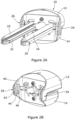
- FIG. 1A A perspective view of an insertion instrument 10 according to a first example is shown in Figure 1A .
- the insertion instrument 10 comprises a superior support 12, an inferior support 14, a pair of superior arms consisting of a first superior arm 16 and a second superior arm 18, and a pair of inferior arms consisting of a first inferior arm 20 and a second inferior arm 22.
- the pair of superior arms 16, 18 are mounted on the superior support 12 such that they extend from spaced apart locations on the superior support and such that the superior arms are substantially parallel.
- the pair of inferior arms 20, 22 are mounted on the inferior support 14 such that they extend from spaced apart locations on the inferior support 14 and such that the inferior arms are substantially parallel.
- Each of the four arms 16, 18, 20, 22 is mounted on its respective support for rotation of the arm relative to the support and about the longitudinal axis of the arm; otherwise, the arm is immovable in relation to the support.
- the superior support 12 and the inferior support 14 are mechanically coupled to each other by a first hinge mechanism 24 and a second hinge mechanism 26.
- the first hinge mechanism 24 is at a first side of the superior and inferior supports 12, 14 and the second hinge mechanism 26 is at a second side of the superior and inferior supports, the first and second sides facing in opposite directions.
- the first and second hinge mechanisms 24, 26 are described further below with reference to Figures 2A and 2B .
- the first and second hinge mechanisms 24, 26 allow the superior support 12 and the inferior support 14 to rotate relative to each other and for the superior and inferior supports to be moved together and apart whilst restricting other relative movement of superior and inferior supports such as in the longitudinal direction of the arms, or in the direction of separation of the superior arms or of the inferior arms.
- the superior support 12 and the inferior support 14 thus rotate about a support axis which is substantially orthogonal to a longitudinal axis of the arms 16, 18, 20, 22 and substantially orthogonal to a direction of separation of the superior and inferior supports.
- the pair of superior arms 16, 18 moves with the superior support 12 and the pair of inferior arms 20, 22 moves with the inferior support 14.
- Relative rotation of the superior and inferior supports 12, 14 therefore causes the pair of superior arms 16, 18 and the pair of inferior arms 20, 22 to rotate relative each other. Also, movement of the superior and inferior supports 12, 14 together and apart moves the pair of superior arms 16, 18 and the pair of inferior arms 20, 22 together and apart.
- the first and second hinge mechanisms 24, 26 allow for relative rotation of superior and inferior supports 12, 14 at the same time as movement of the superior and inferior supports 12, 14 together and apart.
- FIG. 1B A side view of the distal ends of the arms of the insertion instrument 10 of Figure 1A is shown in Figure 1B .
- the first superior arm 16 and the first inferior arm 20 can be seen in Figure 1B to be slightly spaced apart and extending in parallel.
- the superior and inferior supports 12, 14 can be manipulated by the surgeon to increase their separation and to angle the pair of superior arms 16, 18 and the pair of inferior arms 20, 22 relative to each other.
- each of the four arms tapers towards its distal end with a distal portion 28 having the form of a cylinder.
- each distal portion 28 is sized and shaped to be a snug fit in a respective recess 52, 54, 62, 64 proved in the superior and inferior endplates 50, 60 of an anterior lumbar interbody fusion (ALIF) device whereby the superior and inferior endplates are supported by the four arms.
- ALIF anterior lumbar interbody fusion
- the superior and inferior endplates can therefore be manipulated by the surgeon by movement of the superior and inferior supports 12, 14 while the superior and inferior endplates 50, 60 are supported properly by the four arms.
- a protrusion 30 extends from the surrounding surface of each distal portion 28.
- Each of the superior and inferior endplates of the ALIF device defines a pair of recesses 52, 54 and 62, 64 in the anterior side of the endplate with the recesses in each pair spaced apart in the transverse direction.
- Each surface of the endplate that defines the recess 52, 54, 62, 64 has a linear channel in the wall of the recess which extends from the mouth of the recess into the depth of the recess. Furthermore, the furthest most reach of the linear channel is terminated by a circumferentially extending portion of channel in the wall of the recess.
- the protrusion 30 When the distal portion 28 is inserted into a corresponding recess 52, 54, 62, 64 in an endplate, the protrusion 30 is received in the linear channel in the wall of the recess and travels along the linear channel as the distal portion 28 is progressively further received in the recess. When the distal portion 28 is fully received in the recess 52, 54, 62, 64, the protrusion 30 is at the furthest most reach of the linear channel. The surgeon then rotates each arm around its longitudinal axis within the support whereby the protrusion 30 travels along the circumferentially extending portion of channel at the end of the linear channel.
- Reception of the protrusion 30 in the circumferentially extending portion of channel presents resistance to withdrawal of the distal portion 28 of the arm from the recess 52, 54, 62, 64 in the endplate.
- the four arms are thus securely attached to respective locations on the endplates.
- each of the first and second inferior arms 20, 22 has a hinge 32 between 50 mm and 70 mm from the distal end of the arm.
- the hinge 32 allows for a distal portion 34 between the distal end and the hinge and a proximal portion 36 between the hinge and the inferior support to rotate relative to each other.
- the hinge 32 rotates about a hinge axis which is substantially parallel to the support axis whereby the distal portion 34 of the first inferior arm 20 rotates towards and away from the first superior arm 16 and the distal portion 34 of the second inferior arm 22 rotates towards and away from the second superior arm 18.
- the first and second superior arms 16, 18 are unarticulated.
- the insertion instrument is formed from a standard surgical instrument metal, such as stainless steel.
- the insertion instrument is formed from a plastics material, such as polycarbonate or nylon.
- An insertion instrument formed from a plastics material is typically for single use before disposal.
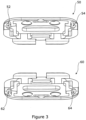
- Figure 2A shows a perspective view of the insertion instrument 10 of Figure 1A looking from distal ends of the arms towards the superior and inferior supports 12, 14.
- the pair of superior arms 16, 18 are mounted on the superior support 12 such that they move with the superior support
- the pair of inferior arms 20, 22 are mounted on the inferior support 14 such that they move with the inferior support.
- the four arms are mounted on the superior and inferior supports 12, 14 such that the four arms extend between the first and second hinge mechanisms 24, 26.
- FIG. 2B The perspective view of Figure 2A with the arms removed is shown in Figure 2B .
- a superior support lug 40 extends from one side of a main body of the superior support 12 in the direction of the arms and an inferior support lug 42 extends from the same one side of a main body of the inferior support 14 in a direction of the arms.
- the superior support lug 40 and the inferior support lug 42 overlap.
- the same structure of superior and inferior support lugs is provided at the other side of the superior and inferior supports.
- the second hinge mechanism 26 is constituted by a cylindrical protrusion 44 which extends towards the arms from the superior support lug 40 and a slot 46 defined in the inferior support lug 42.
- the slot 46 extends in a direction of separation of the pair of superior arms and the pair of inferior arms from each other.
- the protrusion 44 is received in the slot 46 whereby the protrusion can rotate in the slot and also travel along the slot.
- the first hinge mechanism 24 is constituted in the same way with the exception that it is the mirror image of the second hinge mechanism 26 such that, for example, the slots are in registration with each other and the protrusions are aligned and extend towards each other.
- the first hinge and second hinge mechanisms 24, 26 thus allow the superior and inferior supports 12, 14 to be rotated relative to each other and for the superior and inferior supports to be moved together and apart.
- the superior and inferior endplates 50, 60 are attached to their respective pair of arms 16, 18, 20, 22 by insertion into and locking in of each arm in its respective recess 52, 54, 62, 64.
- the surgeon uses the insertion instrument to introduce the superior and inferior endplates to the patient's intervertebral space.
- the surgeon manipulates the superior and inferior supports 12, 14 of the insertion instrument 10 to achieve a desired separation between the superior and inferior endplates and hence height of intervertebral device and a desired angle between the superior and inferior endplates, whether the angle is lordotic and/or transverse.
- the hinges 32 in the inferior arms 20, 22 reduce extent to which there is separation between the pair of superior arms 16, 18 and the pair of inferior arms 20, 22 at their proximal ends to thereby allow for the abdominal incision, by which the superior and inferior endplates are admitted, to be smaller.
- the insertion instrument 10 is being used in the like of an L5-S1 procedure, the disposition of the arms by virtue of the hinges reduces likelihood of the pair of inferior arms colliding with the pubic symphysis.
- sizing trials are carried out to determine desired height and angle for the intervertebral device. Such sizing trials are carried out in accordance with a known approach and are therefore described no further.
- desired height and angle have been determined, a core of appropriate height and angle is selected and inserted between the superior and inferior endplates 50, 60 being held by the insertion instrument 10 in the intervertebral space. Core insertion is described below with reference to Figure 4 .
- the surgeon rotates each of the four arms 16, 18, 20, 22 in the opposite direction to the direction to achieve locking of the arms in their recesses 52, 54, 62, 64.
- the protrusion 30 on the arm travels back along the circumferentially extending portion of channel until the protrusion reaches the linear channel defined in the wall of the recess.
- the protrusion 30 is thus positioned so that it may travel back along the linear channel to thereby allow for the distal end of the arm bearing the protrusion to be withdrawn from the recess.
- the insertion instrument 10 is thus detached from the superior and inferior endplates 50, 60 leaving the superior and inferior endplates with core in place in the intervertebral space.
- the insertion instrument 10 is then withdrawn from the patient's body through the incision that admitted the insertion instrument at the start of the surgical procedure.
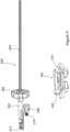
- FIG. 4 shows a core 100 to be inserted and a core inserter 200 which is used in conjunction with the insertion instrument 10 to insert the core.
- the core 100 has an elongate protrusion 102 at each transverse side at the superior surface of the core with each elongate protrusion 102 extending in the anteriorposterior direction.
- the core inserter 200 comprises a core inserter support 202 and an elongate cylindrical member 204.
- a core inserter knob 206 is rotatably mounted on the core inserter support 202.
- the elongate cylindrical member 204 threadedly engages with the core inserter knob 206 whereby the cylindrical member moves through the core inserter support upon rotation of the core inserter knob 206 on the core inserter support 202.
- the core inserter support 202 comprises an attachment mechanism 208 which enables the core inserter support 202 to be removably and threadedly attached to the superior or inferior support 12, 14 of the insertion instrument 10 and such that the cylindrical member 204 is directed between the pair of superior arms 16, 18 and the pair of inferior arms 20, 22 of the insertion instrument 10.
- the attachment mechanism 208 further it comprises a screw member 210 which threadedly engages with a bore defined in the anterior face of the superior or inferior support 12, 14.
- the core 100 is positioned between the superior and inferior supports 12, 14 of the insertion instrument 10 and such that the elongate protrusions 102 are received in respective channels defined by the superior support 12.
- the core inserter 200 is attached by way of the attachment mechanism 208 to the superior or inferior support 12, 14 and such that the operative end 212 of the cylindrical member 204 is directed between the pair of superior arms 16, 18 and the pair of inferior arms 20, 22.
- the operative end 212 of the cylindrical member 204 therefore abuts against the core 100 supported by the superior support 12.
- the surgeon rotates the core inserter knob 206 to increase the reach of the operative end 212 of the cylindrical member 204 between the pairs of arms to thereby push the supported core 100 towards the distal ends of the arms of the insertion instrument. Facing surfaces of the superior pair of arms each define a channel with each channel in registration with a respective one of two core supporting channels defined by the superior support.
- the core 100 is therefore supported by the superior pair of arms as the core is driven by the core inserter 200 towards the distal ends of the arms.
- the surgeon continues to rotate the core inserter knob 206 to push the core between the superior and inferior endplates 50, 60.
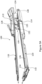
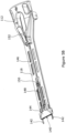
- FIG. 5A A perspective view of an insertion instrument 100 according to the present invention is shown in Figure 5A .
- the insertion instrument 100 comprises a superior support 112, an inferior support 114, one superior arm 116 and one inferior arm 120.
- Each of the superior arm 116 and the inferior arm 120 is generally rectangular when viewed in plan and is of the form of a frame.
- the superior arm 116 is integrally formed with and such that it extends from the superior support 112.
- the inferior arm 120 is integrally formed with and such that it extends from the inferior support 114.
- the superior support 112 and the inferior support 114 are mechanically coupled to each other by a first hinge mechanism 124 and a second hinge mechanism 126.
- the first hinge mechanism 124 is at a first side of the superior and inferior supports 112, 114 and the second hinge mechanism 126 is at a second side of the superior and inferior supports, the first and second sides facing in opposite directions.
- the first and second hinge mechanisms 124, 126 allow the superior support 112 and the inferior support 114 to rotate relative to each other while restricting their movement together and apart and in the transverse direction.
- the first and second hinge mechanisms 124, 126 also allow for movement of the superior support 112 and the inferior support 114 relative to each other in the longitudinal direction, albeit with such movement impeded by spring bias as described further below.
- the superior support 112 and the inferior support 114 thus rotate about a support axis which is substantially orthogonal to a longitudinal axis of the first and second arms 116, 120, and substantially orthogonal to a direction of separation of the superior and inferior supports.
- the superior arm 116 moves with the superior support 112 and the inferior arm 120 moves with the inferior support 114.
- Relative rotation of the superior and inferior supports 112, 114 therefore causes the superior arm 116 and the inferior arm 120 to rotate relative each other. Also, movement of the superior and inferior supports 112, 114 relative to each other in the longitudinal direction moves the superior arm 116 and the inferior arm 120 relative to each other in the longitudinal direction.
- the inferior arm 120 has a hinge 132 between 50 mm and 70 mm from the distal end of the arm.
- the hinge 132 allows for a distal portion 134 between the distal end and the hinge 132 and a proximal portion 136 between the hinge 132 and the inferior support to rotate relative to each other.
- the hinge 132 rotates about a hinge axis which is substantially parallel to the support axis whereby the distal portion 134 of the inferior arm 120 rotates towards and away from the superior arm 116.
- the superior arm 116 is unarticulated.
- first and second hinge mechanisms 124, 126 are of the same form and function.
- Each hinge mechanism 124, 126 comprises first and second parts 122, 125, with the first part 122 integrally formed with the inferior support 114 whereby the first part 122 is immovably mounted on the inferior support.
- the second part 125 is mounted the inferior support 114 for movement relative to the inferior support in the longitudinal direction.
- the disposition of the first and second parts 122, 125 is such that movement of the second part 125 moves the second part towards or away from the first part 122.
- Each hinge mechanism 124, 126 further comprises a spring 126 which is mounted in the inferior support 114 such that its spring bias urges the second part 125 towards the first part 122.
- the opposing faces of the first and second parts 122, 125 each define a recess.
- Each hinge mechanism 124, 126 further comprises a third part in the form of a cylindrical protrusion 128 which is integrally formed with the superior support 112.
- Each cylindrical protrusion 128 is mounted on an integrally formed lug which extends from the superior support 112.
- the cylindrical protrusions 128 of the first and second hinge mechanisms 124, 126 extend towards each other on the inferior support facing side of the superior support and such that they are in registration with each other.
- Relative rotation of the superior and inferior supports 112, 114 is about the two cylindrical protrusions 128.
- Each cylindrical protrusion 128 is received between a respective pair of first and second parts 122, 125.
- the bias exerted by the spring 126 urges the second part 125 towards the first part 122 such that the recesses defined by the opposing faces of the first and second parts 122, 125 fit around the cylindrical protrusion 128.
- Each cylindrical protrusion 128 is thus held between its respective pair of first and second parts 122, 125.
- the lower arm 120 When the lower arm 120 is unbent the lower arm is at maximum reach. When the second part 125 is urged to greatest extent towards the first part 122, the superior support 112 and superior arm 116 are thrust forward to maximum extent relative to the inferior support 114 and inferior arm 120 whereby the distal end of the superior arm 116 is aligned with the distal end of the inferior arm 120. When the lower arm 120 is bent, the reach of the lower arm is reduced whereby the distal ends of the superior and inferior arms 116, 120 are misaligned. The superior and inferior arms 116, 120 are brought back into alignment by pulling the superior support 112 back against the sprung biased second parts 125 whereby the superior support 112 and superior arm 116 are pulled backwards relative to the inferior support 114 and inferior arm 120.
- the recess defined in the face of the second part 125 presents resistance to separation of the superior and inferior supports from each other.
- the second parts 125 are held against the spring bias in their pulled back position and the superior support 112 is moved such that the cylindrical protrusions 128 are moved away from the second parts 125 while being spaced apart from the first parts 122.
- the cylindrical protrusions 128 may then be withdrawn from between the pairs of first and second parts 122, 125 to allow for separation of the superior and inferior supports from each other.
- FIG. 5B A view of a superior part of the insertion instrument of Figure 5A is shown in Figure 5B .
- the superior part comprises the previously described superior support 112 and superior arm 116, amongst other components.
- the superior part further comprises an endplate gripping arrangement 140.
- the endplate gripping arrangement 140 comprises first and second sprung fingers 142 which extend from a distal end of the superior arm 116.
- the first and second sprung fingers 142 are mounted such that they are spaced apart to sufficient extent to receive an endplate component therebetween.
- the first and second fingers 142 are sprung by virtue of the material from which they are formed such that they are inherently sprung and such that the spring bias urges the distal ends of the first and second fingers apart.
- a superior endplate component can be received readily between the first and second fingers in this condition.
- the gripping arrangement 140 further comprise a compression mechanism which releasably engages with the first and second fingers 142 to compress the first and second fingers together towards their distal ends and against their spring bias.
- the superior endplate component is gripped by the first and second fingers 142 when the compression mechanism has engaged with the first and second fingers.
- the compression mechanism comprises a compression body 144 which is movably attached to the superior arm 116 for movement along the superior arm. Furthermore, the compression body 144 is disposed on the superior arm such that movement of the compression body away from the superior support 112 causes the compression body to bear against a shoulder defined by each of the first and second fingers 142. Bearing of the compression body 144 against the shoulders defined by the first and second fingers 142 causes the first and second fingers to deflect towards each other against their spring bias. When the compression body 144 is operating in this fashion, the first and second fingers 142 grip the superior endplate component between oppositely directed sides of the superior endplate component. When the compression body 144 is moved back towards the superior support 112, the compression body no longer bears against the shoulders defined by the first and second fingers 142 to allow the first and second fingers to move apart under their spring bias and to thereby release their grip on the superior endplate component.
- the compression mechanism further comprises a compression mechanism driving arrangement which is supported on the superior arm 116 for movement relative to the superior arm.
- the compression mechanism driving arrangement comprises a first driving member 146 and a second driving member 148 which are hingedly coupled to each other by a first compression mechanism hinge 150.
- the first driving member 146 is coupled at its proximal end to the superior support 112 and is hingedly coupled at its distal end to a proximal end of the second driving member 148.
- the second driving member 148 is attached to the compression body 144 whereby the compression body moves with the second driving member 148.
- Movement of the first driving member 146 causes the second driving member 148 to move back and forth along the superior arm 116 whereby the compression body 144 moves between a first and second finger 142 compressing position and a first and second finger releasing position.
- the first driving member 146 is moved by way of a lever 152 which is rotatably mounted on the superior support 112.
- the lever 152 defines a cam profile that is operative to lock the position of the first driving member 146 and hence the position of the second driving member 148 when the second driving member is at its greatest reach.
- the lock thus provided by the lever 152 therefore locks the grip exerted on the superior endplate component by the first and second fingers 142.
- the first driving member 146 is structured to allow it to flex slightly when the lever 152 is moved to reduce likelihood of jamming of the compression mechanism driving arrangement.
- FIG. 5C A view of an inferior part of the insertion instrument of Figure 5A is shown in Figure 5C .
- the inferior part comprises the previously described inferior support 114 and inferior arm 120, amongst other components.
- the inferior part further comprises an endplate gripping arrangement 140.
- Form and function of the endplate gripping arrangement 140 of the inferior part is common to the form and function of the endplate gripping arrangement 140 of the superior part except as will now be described. The reader's attention is directed to the previous description of the endplate gripping arrangement 140 of the superior part in respect of common form and function.
- the compression mechanism driving arrangement of the inferior part comprises a first driving member 154 and a second driving member 148 which are hingedly coupled to each other by a second compression mechanism hinge 156.
- the first driving member 154 is coupled at its proximal end to the inferior support 114 and is hingedly coupled at its distal end to a proximal end of the second driving member 148.
- the second driving member 148 is attached to the compression body 144 whereby the compression body moves with the second driving member 148. Movement of the first driving member 154 causes the second driving member 148 to move back and forth along the inferior arm 120 whereby the compression body 144 moves between a first and second finger 142 compressing position and a first and second finger releasing position.
- the first driving member 154 is urged away from the inferior support 114 by a spring (not shown) mounted at the proximal end of the first driving member 154 which maintains by virtue of its spring bias the compression body 144 in the inferior endplate component gripping condition.
- a release button 158 at the proximal end of the first driving member 154 compresses the spring when the release button is pressed by a user. Compression of the spring releases the first driving member from the bias of the spring to in turn release the compression body 144 from its locked condition and thereby release the inferior endplate component from the grip exerted by the first and second fingers 142.
- the second compression mechanism hinge 156 differs from the first compression mechanism hinge 150 as will now be described.
- the distal end of the first driving member 154 defines a slot which extends generally in a direction of separation of the superior and inferior supports 112, 114.
- the hinge pin of the second compression mechanism hinge 156 is received in and travels along the slot in the distal end of the first driving member 154 to accommodate change in relative disposition of the proximal and distal portions 134, 136 of the inferior arm 120 as their extent of relative angulation changes.
- the axis of rotation of the second compression mechanism hinge 156 is slightly further away from the superior arm 116 than the axis of rotation of the hinge 132 between the proximal and distal portions of the inferior arm 120. Having the axis of rotation of the second compression mechanism hinge 156 offset in this fashion causes the compression mechanism driving arrangement to increase the extent of relative angulation of the inferior arm 120 and such that the distal portion 134 of the inferior arm is urged towards the superior arm 116.
- the insertion instrument according to an embodiment is formed from a standard surgical instrument metal, such as stainless steel.
- the insertion instrument according to an embodiment is formed from a plastics material, such as polycarbonate or nylon.
- An insertion instrument formed from a plastics material is typically for single use before disposal.
- the insertion instrument according to the invention is used as described above with reference to the first example with articulation of the inferior arm of the invention providing the same benefits as articulation of the two inferior arms of the first example.
Landscapes
- Health & Medical Sciences (AREA)
- Engineering & Computer Science (AREA)
- Biomedical Technology (AREA)
- Life Sciences & Earth Sciences (AREA)
- Animal Behavior & Ethology (AREA)
- Surgery (AREA)
- Orthopedic Medicine & Surgery (AREA)
- Transplantation (AREA)
- Veterinary Medicine (AREA)
- Public Health (AREA)
- Heart & Thoracic Surgery (AREA)
- General Health & Medical Sciences (AREA)
- Physical Education & Sports Medicine (AREA)
- Vascular Medicine (AREA)
- Oral & Maxillofacial Surgery (AREA)
- Cardiology (AREA)
- Nuclear Medicine, Radiotherapy & Molecular Imaging (AREA)
- Neurology (AREA)
- Medical Informatics (AREA)
- Molecular Biology (AREA)
- Prostheses (AREA)
Claims (15)
- Ein Einschubinstrument (100) zum Einschieben einer modularen Zwischenwirbelfusionsvorrichtung oder Komponenten davon (50, 60) in einen Zwischenwirbelraum, wobei das Einschubinstrument Folgendes beinhaltet:einen oberen Arm (116), der an einem oberen Stützelement (112) so angebracht ist, dass sich der obere Arm von dem oberen Stützelement erstreckt; undeinen unteren Arm (120), der an einem unteren Stützelement (114) so angebracht ist, dass sich der untere Arm von dem unteren Stützelement erstreckt,wobei das obere Stützelement und das untere Stützelement mechanisch miteinander gekoppelt sind, wodurch: der obere Arm und der untere Arm sich im Allgemeinen in einer gleichen Richtung erstrecken, sodass im Gebrauch jedes von den distalen Enden der oberen und unteren Arme an einem jeweiligen Ort auf einer modularen Zwischenwirbelfusionsvorrichtung oder Komponente davon Eingriff nimmt; und die oberen und untere Stützelemente relativ zueinander rotieren, um eine relative Rotation des oberen Arms und des unteren Arms bereitzustellen, wodurch es eine Bewegung des oberen Arms und des unteren Arms zusammen und auseinander an ihren distalen Enden gibt,wobei einer von dem oberen Arm und dem unteren Arm zwischen seinem distalen Ende und dem jeweiligen einen von dem oberen Stützelement und dem unteren Stützelement nicht gelenkig bewegt ist und wobei der andere von dem oberen Arm und dem unteren Arm ein Scharnier (132) zwischen seinem distalen Ende (134) und dem jeweiligen einen von dem oberen Stützelement und dem unteren Stützelement beinhaltet, wobei das Scharnier das distale Ende des anderen von dem oberen Arm und dem unteren Arm hin zu oder weg von dem einen von dem oberen Arm und dem unteren Arm rotiert, undwobei das Einschubinstrument nur einen oberen Arm (116) und nur einen unteren Arm (120) beinhaltet, wobei der nicht gelenkig bewegte eine von dem oberen Arm und dem unteren Arm unbeweglich an dem jeweiligen einen von den oberen und unteren Stützelementen angebracht ist, der gelenkig bewegte eine von dem oberen Arm und dem unteren Arm proximale und distale Anteile mit dem Scharnier dazwischen beinhaltet und der proximale Anteil unbeweglich an dem jeweiligen einen von den oberen und unteren Stützelementen (112, 114) angebracht ist.
- Einschubinstrument gemäß Anspruch 1, wobei der nicht gelenkig bewegte Arm zwischen seinem distalen Ende und dem jeweiligen einen von dem oberen Stützelement und dem unteren Stützelement im Wesentlichen gerade ist und wobei sich der proximale Anteil von dem jeweiligen einen von dem oberen Stützelement und dem unteren Stützelement zu dem Scharnier erstreckt, wobei der distale Anteil sich von dem Scharnier zu dem distalen Ende des Arms erstreckt, wobei jeder von den proximalen und distalen Anteilen im Wesentlichen gerade ist.
- Einschubinstrument gemäß Anspruch 1 oder 2, wobei das Scharnier zwischen 20 mm und 100 mm von dem distalen Ende des gelenkig bewegten Arms liegt.
- Einschubinstrument gemäß Anspruch 3, wobei das Scharnier zwischen 50 mm und 70 mm von dem distalen Ende des gelenkig bewegten Arms liegt.
- Einschubinstrument gemäß einem der vorhergehenden Ansprüche, wobei das obere Stützelement und das untere Stützelement relativ zueinander um eine Stützachse rotieren, die im Wesentlichen senkrecht zu einer Längsachse der Arme und im Wesentlichen senkrecht zu einer Richtung der Trennung der oberen und unteren Stützelemente ist.
- Einschubinstrument gemäß Anspruch 5, wobei das obere Stützelement und das untere Stützelement mechanisch miteinander gekoppelt sind, um eine Barriere gegen eine Bewegung des oberen Stützelements und des unteren Stützelements relativ zueinander in einer Querrichtung darzustellen.
- Einschubinstrument gemäß einem der vorhergehenden Ansprüche, wobei das obere Stützelement und das untere Stützelement mechanisch miteinander gekoppelt sind: um eine Bewegung des oberen Stützelements und des unteren Stützelements relativ zueinander in einer Richtung der Trennung des oberen und unteren Stützelements im Wesentlichen zu verhindern; und zur Bewegung der oberen und unteren Stützelemente relativ zueinander in einer Längsrichtung der oberen und unteren Arme.
- Einschubinstrument gemäß Anspruch 7, wobei das untere Stützelement eine Federvorspannung beinhaltet, die das Stützelement, das den gelenkig bewegten Arm relativ zu dem anderen von den oberen und unteren Stützelementen in der Längsrichtung stützt, so antreibt, dass das distale Ende des gelenkig bewegten Arms von dem anderen von den oberen und unteren Stützelemente weggetrieben wird.
- Einschubinstrument gemäß Anspruch 8, wobei die distalen Enden der oberen und unteren Arme im Wesentlichen miteinander ausgerichtet sind, wenn die distalen und proximalen Anteile im Verhältnis zueinander entspannt sind, und das Stützelement, das den gelenkig bewegten Arm stützt, nicht in der Längsrichtung gegen die Federvorspannung bewegt wird, und wobei die distalen Enden der oberen und unteren Arme im Wesentlichen miteinander ausgerichtet sind, wenn die distalen und proximalen Anteile im Verhältnis zueinander gespannt sind, und das Stützelement, das den gelenkig bewegten Arm stützt, in der Längsrichtung gegen die Federvorspannung bewegt wird.
- Einschubinstrument gemäß einem der vorhergehenden Ansprüche, das eine Greifanordnung (140) für jeden von dem oberen Arm und dem unteren Arm beinhaltet, wobei jede Greifanordnung erste und zweite gefederte Finger (142) beinhaltet, die sich von einem distalen Ende des jeweiligen Arms erstrecken, wobei die ersten und zweiten gefederten Finger in einem ausreichendem Maße beabstandet sind, um eine Endplattenkomponente der modularen Zwischenwirbelfusionsvorrichtung dazwischen aufzunehmen.
- Einschubinstrument gemäß Anspruch 10, wobei jede Greifanordnung ferner einen Kompressionsmechanismus beinhaltet, der lösbar Eingriff mit den ersten und zweiten Fingern nimmt, um die ersten und zweiten Finger zu ihren distalen Enden hin und gegen die Federvorspannung zusammenzudrücken, wobei die Endplattenkomponente von den ersten und zweiten Fingern gegriffen wird, wenn der Kompressionsmechanismus Eingriff mit den ersten und zweiten Fingern genommen hat.
- Einschubinstrument gemäß Anspruch 11, wobei der Kompressionsmechanismus einen Kompressionskörper (144) beinhaltet, der beweglich an seinem jeweiligen Arm befestigt ist, wobei der Kompressionskörper zur Bewegung entlang des Arms auf dem Arm angebracht ist, wobei eine Bewegung des Kompressionskörpers entlang des Arms Kompression und Lösen der Kompression der ersten und zweiten Finger bereitstellt.
- Einschubinstrument gemäß Anspruch 11 oder 12, wobei jede Greifanordnung eine Kompressionsmechanismus-Antriebsanordnung beinhaltet, die auf ihrem jeweiligen Arm zur Bewegung relativ zu dem Arm gestützt wird, wobei die Kompressionsmechanismus-Antriebsanordnung ein erstes Antriebselement (146) und ein zweites Antriebselement (148) beinhaltet, die schwenkbar miteinander gekoppelt sind, wobei das erste Antriebselement an seinem proximalen Ende mit dem jeweiligen einen von dem oberen Stützelement und dem unteren Stützelement gekoppelt ist und an seinem distalen Ende mit einem proximalen Ende des zweiten Antriebselements schwenkbar gekoppelt ist, wobei das zweite Antriebselement an dem Kompressionsmechanismus befestigt ist, wodurch sich der Kompressionsmechanismus mit dem zweiten Antriebselement bewegt.
- Einschubinstrument gemäß einem der vorhergehenden Ansprüche, wobei das Scharnier (132) keine Sperre zum Halten des distalen Anteils in einem festgelegten Winkel an dem proximalen Anteil aufweist, wodurch das Scharnier sich frei um seine Achse drehen kann.
- Eine Zwischenwirbelvorrichtungs-Einschubbaugruppe, die ein Einschubinstrument gemäß einem der vorhergehenden Ansprüche und eine modulare Zwischenwirbelfusionsvorrichtung beinhaltet, wobei die modulare Zwischenwirbelfusionsvorrichtung eine obere Endplatte (50) und eine untere Endplatte (60) beinhaltet und wobei der obere Arm Eingriff mit der oberen Endplatte nimmt, um die obere Endplatte zu stützen, und der untere Arm Eingriff mit der unteren Endplatte nimmt, um die untere Endplatte zu stützen.
Applications Claiming Priority (2)
| Application Number | Priority Date | Filing Date | Title |
|---|---|---|---|
| GBGB1910640.0A GB201910640D0 (en) | 2019-07-25 | 2019-07-25 | Insertions instruments |
| PCT/GB2020/051789 WO2021014173A1 (en) | 2019-07-25 | 2020-07-24 | Insertion instruments |
Publications (3)
| Publication Number | Publication Date |
|---|---|
| EP4003239A1 EP4003239A1 (de) | 2022-06-01 |
| EP4003239B1 true EP4003239B1 (de) | 2025-06-04 |
| EP4003239C0 EP4003239C0 (de) | 2025-06-04 |
Family
ID=67990443
Family Applications (1)
| Application Number | Title | Priority Date | Filing Date |
|---|---|---|---|
| EP20765060.7A Active EP4003239B1 (de) | 2019-07-25 | 2020-07-24 | Einsetzinstrumente |
Country Status (4)
| Country | Link |
|---|---|
| US (2) | US12137892B2 (de) |
| EP (1) | EP4003239B1 (de) |
| GB (1) | GB201910640D0 (de) |
| WO (1) | WO2021014173A1 (de) |
Families Citing this family (3)
| Publication number | Priority date | Publication date | Assignee | Title |
|---|---|---|---|---|
| GB201910668D0 (en) | 2019-07-25 | 2019-09-11 | Axis Spine Tech Ltd | Assemblies for and methods of determing height and angle of an intervertebral device |
| GB202207714D0 (en) * | 2022-05-25 | 2022-07-06 | Axis Spine Tech Ltd | Insertion instruments |
| GB202404565D0 (en) | 2024-03-28 | 2024-05-15 | Axis Spine Tech Ltd | Insertion instruments |
Citations (1)
| Publication number | Priority date | Publication date | Assignee | Title |
|---|---|---|---|---|
| WO2003037230A2 (de) * | 2001-10-29 | 2003-05-08 | Waldemar Link (Gmbh & Co.) | Instrumentarium zum einsetzen einer zwischenwirbelprothese |
Family Cites Families (50)
| Publication number | Priority date | Publication date | Assignee | Title |
|---|---|---|---|---|
| US6045579A (en) | 1997-05-01 | 2000-04-04 | Spinal Concepts, Inc. | Adjustable height fusion device |
| AU760821B2 (en) * | 1998-10-02 | 2003-05-22 | Synthes Gmbh | Spinal disc space distractor |
| US6113637A (en) | 1998-10-22 | 2000-09-05 | Sofamor Danek Holdings, Inc. | Artificial intervertebral joint permitting translational and rotational motion |
| US6102950A (en) | 1999-01-19 | 2000-08-15 | Vaccaro; Alex | Intervertebral body fusion device |
| ATE354324T1 (de) | 1999-09-14 | 2007-03-15 | Spine Solutions Inc | Einsetzinstrument für ein zwischenwirbelimplantat |
| DE10116412C1 (de) | 2001-04-02 | 2003-01-16 | Ulrich Gmbh & Co Kg | Implantat zum Einsetzen zwischen Wirbelkörper der Wirbelsäule |
| US6726720B2 (en) | 2002-03-27 | 2004-04-27 | Depuy Spine, Inc. | Modular disc prosthesis |
| US7169153B2 (en) | 2002-06-10 | 2007-01-30 | Depuy Spine | Surgical instrument for inserting intervertebral prosthesis |
| US7214243B2 (en) | 2002-10-21 | 2007-05-08 | 3Hbfm, Llc | Intervertebral disk prosthesis |
| US8388686B2 (en) | 2002-12-17 | 2013-03-05 | Max Aebi | Intervertebral implant with tiltable joint parts |
| EP1608270A2 (de) * | 2003-03-31 | 2005-12-28 | DePuy Spine, Inc. | Verfahren und vorrichtung zum einführen einer bandscheibenprothese |
| CA2573340A1 (en) | 2004-07-09 | 2006-02-16 | Pioneer Laboratories, Inc. | Skeletal reconstruction device |
| US7547309B2 (en) | 2004-09-23 | 2009-06-16 | Spine Solutions, Inc. | Distractor for lumbar insertion instrument |
| US7806901B2 (en) | 2006-03-17 | 2010-10-05 | Depuy Spine, Inc. | Arthroplasty final seating instruments |
| US8366776B2 (en) | 2006-04-13 | 2013-02-05 | Warsaw Orthopedic, Inc. | Vertebral implants having predetermined angular correction and method of use |
| US8128700B2 (en) | 2006-09-13 | 2012-03-06 | Synthes Usa, Llc | Allograft intervertebral implant and method of manufacturing the same |
| US9381098B2 (en) * | 2006-09-28 | 2016-07-05 | Spinal Kinetics, Inc. | Tool systems for implanting prosthetic intervertebral discs |
| US8465546B2 (en) * | 2007-02-16 | 2013-06-18 | Ldr Medical | Intervertebral disc prosthesis insertion assemblies |
| US8480715B2 (en) | 2007-05-22 | 2013-07-09 | Zimmer Spine, Inc. | Spinal implant system and method |
| US9526628B2 (en) | 2008-11-14 | 2016-12-27 | David Krueger | Spinal fusion device |
| US8308804B2 (en) | 2008-11-14 | 2012-11-13 | David Krueger | Spinal fusion device |
| US20110153020A1 (en) | 2009-12-17 | 2011-06-23 | Custom Spine, Inc. | Anterior Lumbar Interbody |
| US8465547B2 (en) | 2010-01-27 | 2013-06-18 | Warsaw Orthopedic, Inc. | Modular interbody devices and methods of use |
| US9592063B2 (en) | 2010-06-24 | 2017-03-14 | DePuy Synthes Products, Inc. | Universal trial for lateral cages |
| US8454700B2 (en) | 2011-10-04 | 2013-06-04 | Zimmer Spine, Inc. | Interbody vertebral spacer |
| US20130103153A1 (en) | 2011-10-24 | 2013-04-25 | Warsaw Orthopedic, Inc. | Interbody implant system and methods of use |
| US8936599B2 (en) | 2011-11-02 | 2015-01-20 | Tenzin Llc | Translational instrumentation for spondylolisthesis and scoliosis reduction |
| US9526627B2 (en) | 2011-11-17 | 2016-12-27 | Exactech, Inc. | Expandable interbody device system and method |
| WO2013184946A1 (en) | 2012-06-06 | 2013-12-12 | Medivest, Llc | Expandable tissue spacer implant and method of use |
| US9498349B2 (en) | 2012-10-09 | 2016-11-22 | Titan Spine, Llc | Expandable spinal implant with expansion wedge and anchor |
| DE102012023042B3 (de) | 2012-11-26 | 2013-11-28 | Spontech Spine Intelligence Group Ag | Expandierbarer Cage zur interkorporellen Fusion von Lendenwirbeln |
| US8663332B1 (en) | 2012-12-13 | 2014-03-04 | Ouroboros Medical, Inc. | Bone graft distribution system |
| US9585765B2 (en) | 2013-02-14 | 2017-03-07 | Globus Medical, Inc | Devices and methods for correcting vertebral misalignment |
| EP2999438B1 (de) | 2013-05-20 | 2022-05-18 | K2M, Inc. | Einstellbares implantat und einsetzwerkzeug |
| US9801734B1 (en) | 2013-08-09 | 2017-10-31 | Nuvasive, Inc. | Lordotic expandable interbody implant |
| US9402739B2 (en) | 2014-02-07 | 2016-08-02 | Globus Medical, Inc. | Variable lordosis spacer and related methods of use |
| FR3020756B1 (fr) | 2014-05-06 | 2022-03-11 | Ldr Medical | Implant vertebral, dispositif de fixation vertebrale d'implant et instrumentation d'implantation |
| US9585762B2 (en) | 2014-10-09 | 2017-03-07 | K2M, Inc. | Expandable spinal interbody spacer and method of use |
| US9632020B2 (en) | 2014-10-22 | 2017-04-25 | The Boeing Company | Non-linear optical ellipsometry for surface monitoring and characterization |
| US10363142B2 (en) | 2014-12-11 | 2019-07-30 | K2M, Inc. | Expandable spinal implants |
| US9060876B1 (en) | 2015-01-20 | 2015-06-23 | Ouroboros Medical, Inc. | Stabilized intervertebral scaffolding systems |
| KR101674491B1 (ko) | 2015-07-10 | 2016-11-09 | 주식회사 메드릭스 | 최소 침습 수술용 케이지 장치 |
| US11020241B2 (en) | 2016-02-23 | 2021-06-01 | Life Spine, Inc. | Expandable lateral spine cage with reverse dovetail configuration |
| US10052215B2 (en) | 2016-06-29 | 2018-08-21 | Globus Medical, Inc. | Expandable fusion device and method of installation thereof |
| US9883953B1 (en) | 2016-09-21 | 2018-02-06 | Integrity Implants Inc. | Stabilized laterovertically-expanding fusion cage systems with tensioner |
| GB201818847D0 (en) | 2018-11-19 | 2019-01-02 | Axis Spine Tech Ltd | Intervertebral devices |
| GB201902002D0 (en) | 2019-02-13 | 2019-04-03 | Axis Spine Tech Ltd | Intervertebral devices |
| GB201818850D0 (en) | 2018-11-19 | 2019-01-02 | Axis Spine Tech Ltd | Intervertebral devices |
| GB201818849D0 (en) | 2018-11-19 | 2019-01-02 | Axis Spine Tech Ltd | Intervertebral devices |
| GB201910668D0 (en) | 2019-07-25 | 2019-09-11 | Axis Spine Tech Ltd | Assemblies for and methods of determing height and angle of an intervertebral device |
-
2019
- 2019-07-25 GB GBGB1910640.0A patent/GB201910640D0/en not_active Ceased
-
2020
- 2020-07-24 EP EP20765060.7A patent/EP4003239B1/de active Active
- 2020-07-24 WO PCT/GB2020/051789 patent/WO2021014173A1/en not_active Ceased
- 2020-07-24 US US17/629,349 patent/US12137892B2/en active Active
-
2024
- 2024-11-11 US US18/942,829 patent/US20250221699A1/en active Pending
Patent Citations (1)
| Publication number | Priority date | Publication date | Assignee | Title |
|---|---|---|---|---|
| WO2003037230A2 (de) * | 2001-10-29 | 2003-05-08 | Waldemar Link (Gmbh & Co.) | Instrumentarium zum einsetzen einer zwischenwirbelprothese |
Also Published As
| Publication number | Publication date |
|---|---|
| WO2021014173A1 (en) | 2021-01-28 |
| EP4003239C0 (de) | 2025-06-04 |
| EP4003239A1 (de) | 2022-06-01 |
| US20250221699A1 (en) | 2025-07-10 |
| US12137892B2 (en) | 2024-11-12 |
| GB201910640D0 (en) | 2019-09-11 |
| US20220249081A1 (en) | 2022-08-11 |
Similar Documents
| Publication | Publication Date | Title |
|---|---|---|
| US11944551B2 (en) | Expandable vertebral implant | |
| US20250221699A1 (en) | Insertion instruments | |
| US10772737B2 (en) | Expandable intervertebral implant | |
| US10299934B2 (en) | Expandable vertebral implant | |
| US9480579B2 (en) | Expandable intervertebral implant | |
| US8267997B2 (en) | Vertebral interbody compression implant | |
| US9486326B2 (en) | Intervertebral implant | |
| US9572677B2 (en) | Expandable intervertebral implant | |
| US8500747B2 (en) | Instruments and methods for spinal implant revision | |
| US9474622B2 (en) | Expandable intervertebral implant | |
| US20100249792A1 (en) | Instruments and techniques for separating bony structures | |
| EP2508150A1 (de) | Einstellbare Vorrichtung zum Einsetzen eines Implantats | |
| EP2967908B1 (de) | Expandierbares bandscheibenimplantat | |
| EP3225212B1 (de) | Expandierbares bandscheibenimplantat | |
| US20250302641A1 (en) | Insertion instruments |
Legal Events
| Date | Code | Title | Description |
|---|---|---|---|
| STAA | Information on the status of an ep patent application or granted ep patent |
Free format text: STATUS: UNKNOWN |
|
| STAA | Information on the status of an ep patent application or granted ep patent |
Free format text: STATUS: THE INTERNATIONAL PUBLICATION HAS BEEN MADE |
|
| PUAI | Public reference made under article 153(3) epc to a published international application that has entered the european phase |
Free format text: ORIGINAL CODE: 0009012 |
|
| STAA | Information on the status of an ep patent application or granted ep patent |
Free format text: STATUS: REQUEST FOR EXAMINATION WAS MADE |
|
| 17P | Request for examination filed |
Effective date: 20220215 |
|
| AK | Designated contracting states |
Kind code of ref document: A1 Designated state(s): AL AT BE BG CH CY CZ DE DK EE ES FI FR GB GR HR HU IE IS IT LI LT LU LV MC MK MT NL NO PL PT RO RS SE SI SK SM TR |
|
| DAV | Request for validation of the european patent (deleted) | ||
| DAX | Request for extension of the european patent (deleted) | ||
| GRAP | Despatch of communication of intention to grant a patent |
Free format text: ORIGINAL CODE: EPIDOSNIGR1 |
|
| STAA | Information on the status of an ep patent application or granted ep patent |
Free format text: STATUS: GRANT OF PATENT IS INTENDED |
|
| INTG | Intention to grant announced |
Effective date: 20241028 |
|
| GRAJ | Information related to disapproval of communication of intention to grant by the applicant or resumption of examination proceedings by the epo deleted |
Free format text: ORIGINAL CODE: EPIDOSDIGR1 |
|
| STAA | Information on the status of an ep patent application or granted ep patent |
Free format text: STATUS: REQUEST FOR EXAMINATION WAS MADE |
|
| GRAP | Despatch of communication of intention to grant a patent |
Free format text: ORIGINAL CODE: EPIDOSNIGR1 |
|
| STAA | Information on the status of an ep patent application or granted ep patent |
Free format text: STATUS: GRANT OF PATENT IS INTENDED |
|
| INTC | Intention to grant announced (deleted) | ||
| RIN1 | Information on inventor provided before grant (corrected) |
Inventor name: SHERMAN, MICHAEL Inventor name: BARFIELD, CHARLES Inventor name: REAH, CHRISTOPHER Inventor name: ARCOS, JONATHAN |
|
| INTG | Intention to grant announced |
Effective date: 20250117 |
|
| RAP3 | Party data changed (applicant data changed or rights of an application transferred) |
Owner name: AXIS SPINE TECHNOLOGIES LTD |
|
| GRAS | Grant fee paid |
Free format text: ORIGINAL CODE: EPIDOSNIGR3 |
|
| GRAA | (expected) grant |
Free format text: ORIGINAL CODE: 0009210 |
|
| STAA | Information on the status of an ep patent application or granted ep patent |
Free format text: STATUS: THE PATENT HAS BEEN GRANTED |
|
| AK | Designated contracting states |
Kind code of ref document: B1 Designated state(s): AL AT BE BG CH CY CZ DE DK EE ES FI FR GB GR HR HU IE IS IT LI LT LU LV MC MK MT NL NO PL PT RO RS SE SI SK SM TR |
|
| REG | Reference to a national code |
Ref country code: GB Ref legal event code: FG4D |
|
| REG | Reference to a national code |
Ref country code: CH Ref legal event code: EP |
|
| REG | Reference to a national code |
Ref country code: DE Ref legal event code: R096 Ref document number: 602020052313 Country of ref document: DE |
|
| REG | Reference to a national code |
Ref country code: IE Ref legal event code: FG4D |
|
| U01 | Request for unitary effect filed |
Effective date: 20250623 |
|
| U07 | Unitary effect registered |
Designated state(s): AT BE BG DE DK EE FI FR IT LT LU LV MT NL PT RO SE SI Effective date: 20250627 |
|
| U20 | Renewal fee for the european patent with unitary effect paid |
Year of fee payment: 6 Effective date: 20250719 |
|
| PG25 | Lapsed in a contracting state [announced via postgrant information from national office to epo] |
Ref country code: ES Free format text: LAPSE BECAUSE OF FAILURE TO SUBMIT A TRANSLATION OF THE DESCRIPTION OR TO PAY THE FEE WITHIN THE PRESCRIBED TIME-LIMIT Effective date: 20250604 |
|
| PG25 | Lapsed in a contracting state [announced via postgrant information from national office to epo] |
Ref country code: NO Free format text: LAPSE BECAUSE OF FAILURE TO SUBMIT A TRANSLATION OF THE DESCRIPTION OR TO PAY THE FEE WITHIN THE PRESCRIBED TIME-LIMIT Effective date: 20250904 Ref country code: GR Free format text: LAPSE BECAUSE OF FAILURE TO SUBMIT A TRANSLATION OF THE DESCRIPTION OR TO PAY THE FEE WITHIN THE PRESCRIBED TIME-LIMIT Effective date: 20250905 |
|
| PG25 | Lapsed in a contracting state [announced via postgrant information from national office to epo] |
Ref country code: PL Free format text: LAPSE BECAUSE OF FAILURE TO SUBMIT A TRANSLATION OF THE DESCRIPTION OR TO PAY THE FEE WITHIN THE PRESCRIBED TIME-LIMIT Effective date: 20250604 |
|
| PGFP | Annual fee paid to national office [announced via postgrant information from national office to epo] |
Ref country code: GB Payment date: 20250716 Year of fee payment: 6 |
|
| PG25 | Lapsed in a contracting state [announced via postgrant information from national office to epo] |
Ref country code: HR Free format text: LAPSE BECAUSE OF FAILURE TO SUBMIT A TRANSLATION OF THE DESCRIPTION OR TO PAY THE FEE WITHIN THE PRESCRIBED TIME-LIMIT Effective date: 20250604 |
|
| PGFP | Annual fee paid to national office [announced via postgrant information from national office to epo] |
Ref country code: CH Payment date: 20250801 Year of fee payment: 6 |
|
| PG25 | Lapsed in a contracting state [announced via postgrant information from national office to epo] |
Ref country code: RS Free format text: LAPSE BECAUSE OF FAILURE TO SUBMIT A TRANSLATION OF THE DESCRIPTION OR TO PAY THE FEE WITHIN THE PRESCRIBED TIME-LIMIT Effective date: 20250904 |