EP4002880A1 - Multi-path input-driving small loudspeaker and mid-treble loudspeaker - Google Patents
Multi-path input-driving small loudspeaker and mid-treble loudspeaker Download PDFInfo
- Publication number
- EP4002880A1 EP4002880A1 EP19938033.8A EP19938033A EP4002880A1 EP 4002880 A1 EP4002880 A1 EP 4002880A1 EP 19938033 A EP19938033 A EP 19938033A EP 4002880 A1 EP4002880 A1 EP 4002880A1
- Authority
- EP
- European Patent Office
- Prior art keywords
- voice coil
- magnetic
- magnetic circuit
- yoke
- mounting holes
- Prior art date
- Legal status (The legal status is an assumption and is not a legal conclusion. Google has not performed a legal analysis and makes no representation as to the accuracy of the status listed.)
- Granted
Links
Images



Classifications
-
- H—ELECTRICITY
- H04—ELECTRIC COMMUNICATION TECHNIQUE
- H04R—LOUDSPEAKERS, MICROPHONES, GRAMOPHONE PICK-UPS OR LIKE ACOUSTIC ELECTROMECHANICAL TRANSDUCERS; ELECTRIC HEARING AIDS; PUBLIC ADDRESS SYSTEMS
- H04R9/00—Transducers of moving-coil, moving-strip, or moving-wire type
- H04R9/06—Loudspeakers
- H04R9/063—Loudspeakers using a plurality of acoustic drivers
-
- H—ELECTRICITY
- H04—ELECTRIC COMMUNICATION TECHNIQUE
- H04R—LOUDSPEAKERS, MICROPHONES, GRAMOPHONE PICK-UPS OR LIKE ACOUSTIC ELECTROMECHANICAL TRANSDUCERS; ELECTRIC HEARING AIDS; PUBLIC ADDRESS SYSTEMS
- H04R9/00—Transducers of moving-coil, moving-strip, or moving-wire type
- H04R9/02—Details
- H04R9/025—Magnetic circuit
-
- H—ELECTRICITY
- H04—ELECTRIC COMMUNICATION TECHNIQUE
- H04R—LOUDSPEAKERS, MICROPHONES, GRAMOPHONE PICK-UPS OR LIKE ACOUSTIC ELECTROMECHANICAL TRANSDUCERS; ELECTRIC HEARING AIDS; PUBLIC ADDRESS SYSTEMS
- H04R9/00—Transducers of moving-coil, moving-strip, or moving-wire type
- H04R9/06—Loudspeakers
Definitions
- the present invention relates to the loudspeaker field, in particular to a small loudspeaker and mid-treble loudspeaker with multi-input-drives.
- the existing traditional small loudspeakers generally adopt a structure comprising a dish-shaped cone of plastic film combined with a voice coil, a groove for fixing the voice coil is arranged at the center of the bottom of the cone, and one end of the voice coil with a single signal input is fixed on the center groove of the bottom of the cone to form a small loudspeaker vibration system, and this small loudspeaker can only be used for single-channel signal input, while single-channel audio signal input has limitations on the original sound reproduction, and the combination of a single voice coil and the cone has a higher requirement of the rigidity for the cone.
- a fixed voice coil step is arranged at the center of the bottom of the cone, and one end of the voice coil with multi-signal input is fixed on the center step of the bottom of the cone, where the voice coil is formed by stacking multiple sets of coils from inside to outside, to form a small loudspeaker vibration system, and this small loudspeaker can be used for multi-signal input, however, since this type of loudspeaker has multiple sets of coils wound on one voice coil, the weight of the voice coil is increased, and the sensitivity of the small loudspeaker may be reduced, which has limitations on the reproduction of the original sound.
- mid-treble loudspeakers most generally adopt a structure comprising a dome sound membrane combined with a voice coil, one end of the voice coil is directly fixed on a center groove on the opposite side of the dome sound membrane to form a treble vibration system, and this mid-treble loudspeaker can only be used for single-channel signal input, while single-channel audio signal input has limitations on the original sound reproduction, and the combination of a single voice coil and the sound membrane has a higher requirement of the rigidity for the sound membrane.
- a fixed voice coil step is arranged at the center of the bottom of the sound membrane, and one end of the voice coil with multi-signal input is fixed on the center step of the bottom of the sound membrane, where the voice coil is formed by stacking multiple sets of coils from inside to outside, to form a mid-treble vibration system, and this mid-treble loudspeaker can be used for multi-signal input, however, since this type of loudspeaker has multiple sets of coils wound on one voice coil, the weight of the voice coil is increased by winding multiple sets of coils on one voice coil, and the sensitivity of the mid-treble loudspeaker may be reduced, which has limitations on the reproduction of the original sound.
- the first purpose of the present invention is to provide a small loudspeaker with multi-input-drives, which increases the sensitivity of the small loudspeaker, improves the intelligiblity of the small loudspeaker, and reduces the distortion.
- the second purpose of the present invention is to provide a mid-treble loudspeaker with multi-input-drives, which increases the sensitivity of the mid-treble loudspeaker, improves the intelligiblity of the mid-treble loudspeaker, and reduces the distortion.
- multi-input refers to multiple audio signal inputs
- multi-input driving refers to multiple audio signals input to multiple voice coils, and the multiple voice coils jointly drive the loudspeaker to produce sound.
- a technical solution employed by the present invention is: a small loudspeaker with multi-input-drives, comprising a frame, and a cone arranged on the frame, the small loudspeaker further comprises a plurality of input driving mechanisms, each of the input driving mechanisms comprises a voice coil and a magnetic circuit assembly for driving the voice coil to vibrate, each of the magnetic circuit assemblies comprises a U-yoke having an inner cavity, a magnetic steel and a magnetic pole core arranged within the U-yoke, a magnetic gap is formed between an inner wall of the U-yoke and the magnetic steel or the magnetic pole core, the voice coil is inserted in the magnetic gap and capable of moving in an up-and-down direction; a plurality of magnetic circuit mounting holes are opened on the frame, and at most one U-yoke is arranged below each of the magnetic circuit mounting holes, and the voice coils respectively pass through the corresponding magnetic circuit mounting holes, and lower portions of the voice coils are respectively inserted into the magnetic gaps; the cone has a plurality of input driving
- the small loudspeaker in the present invention is a small loudspeaker without damper.
- the term "small loudspeaker” refers to a loudspeaker with a size of less than 100 mm, which is suitable for use in headsets and other equipment, with a frequency range of 50 to 15000 Hz.
- the input driving mechanisms there are three or more of the input driving mechanisms, and the three or more input driving mechanisms are arranged at equal intervals along a circle.
- the plurality of input driving mechanisms are arranged circularly and evenly.
- the three or more input driving mechanisms are arranged linearly, or in an array.
- the plurality of input driving mechanisms are arranged linearly or in an array, and the cone adopts an oval shape or a rectangular shape.
- the cone has a cone bottom that is a round flat-sheet, and a center of the circle coincides with a center of the cone bottom.
- three or more voice coil mounting holes are arranged on the cone bottom, the voice coil mounting holes are arranged at equal intervals along the circle, and each of the voice coil mounting holes is provided with one of the voice coils to connect the voice coils to the cone bottom.
- the cone further comprises a tapered edge portion extending obliquely upwards from an outer edge of the cone bottom, and the tapered edge portion is fixedly connected to the frame through a yoke ring.
- three or more magnetic circuit mounting holes are opened on the frame, the magnetic circuit mounting holes are arranged at equal intervals along the circle, and each of the magnetic circuit mounting holes is provided with one magnetic circuit assembly.
- the upper edge of the U-yoke is fixedly connected to a lower surface of the frame.
- the magnetic steel is neodymium magnetic steel or ferrite magnetic steel.
- each magnetic circuit assembly is composed of a U-yoke, and a magnetic pole core and a neodymium magnetic steel arranged within the U-yoke, and a lower surface of the magnetic pole core closely contacts an upper surface of the neodymium magnetic steel.
- multiple pairs of audio signal input terminals are arranged on an edge of the frame, and each pair of the audio signal input terminals are electrically connected to leads of one voice coil. It simplifies the connection of the product itself and facilitates the connection of audio signal input.
- the plurality of input driving mechanisms are arranged in circular, linear, or an array.
- a mid-treble loudspeaker with multi-input-drives comprising a sound membrane support, and a sound membrane arranged on the sound membrane support
- the mid-treble loudspeaker further comprises a plurality of input driving mechanisms
- each of the input driving mechanism comprises a voice coil and a magnetic circuit assembly for driving the voice coil to vibrate
- each of the magnetic circuit assemblies comprises a U-yoke having an inner cavity, a magnetic steel and a magnetic pole core arranged within the U-yoke, a magnetic gap is formed between an inner wall of the U-yoke and the magnetic steel or the magnetic pole core, the voice coil is inserted in the magnetic gap and capable of moving in an up-and-down direction
- a plurality of magnetic circuit mounting holes are opened on the sound membrane support, and at most one U-yoke is arranged at each magnetic circuit mounting hole, and the voice coils respectively pass through corresponding magnetic circuit mounting holes, and lower portions of the voice coils are respectively inserted into the magnetic gaps
- the mid-treble loudspeaker in the present invention is a mid-treble loudspeaker without damper.
- the term "mid-treble loudspeaker” refers to a loudspeaker with a frequency range of 1500 to 20000 Hz.
- the three or more input driving mechanisms are arranged at equal intervals along a circle, the voice coil support is round as a whole, and a center of the circumference coincides with a center of the voice coil support.
- the plurality of input driving mechanisms are arranged circularly and evenly.
- the three or more input driving mechanisms are arranged linearly, or in an array.
- the plurality of input driving mechanisms are arranged linearly or in an array.
- the sound membrane adopts an oval shape or a rectangular shape.
- three or more voice coil mounting grooves are opened on the voice coil support, the voice coil mounting grooves are arranged at equal intervals along the circle, and each of the voice coil mounting grooves is provided with one voice coil to connect the voice coil to the voice coil support;
- three or more magnetic circuit mounting holes are opened on the sound membrane support, the magnetic circuit mounting holes are arranged at equal intervals along the circle, and each of the magnetic circuit mounting holes is provided with one magnetic circuit assembly.
- the sound membrane has a spherical portion arched upwardly and a yoke ring around an outer edge of the spherical portion, and the yoke ring and the voice coil support are fixedly connected.
- the mid-treble loudspeaker further comprises a sound amplifying cover, and the sound amplifying cover is covered on the sound membrane.
- the upper edge of the U-yoke is fixedly connected to a lower surface of the sound membrane support.
- the magnetic steel is neodymium magnetic steel or ferrite magnetic steel.
- each of the magnetic circuit assemblies is composed of a U-yoke, and a magnetic pole core and a neodymium magnetic steel arranged within the U-yoke, and a lower surface of the magnetic pole core closely contacts an upper surface of the neodymium magnetic steel.
- multiple pairs of audio signal input terminals are arranged on an edge of the sound membrane support, and each pair of audio signal input terminals are electrically connected to leads of one voice coil. It simplifies the connection of the product itself and facilitates the connection of audio signal input.
- the plurality of input driving mechanisms are arranged in circular, linear, or an array.
- the present invention has the following advantages over the prior art: in the small loudspeaker and the mid-treble loudspeaker with multi-input-drives of the present invention, the structure is ingenious and rational, and the original sound reproduction and distortion are better than that of traditional loudspeakers by receiving audio signal input via multiple voice coils; through the input-driving structure formed by a plurality of magnetic circuit assemblies, the sensitivity of the loudspeaker is increased, and the intelligiblity of the loudspeaker is improved.
- the multi-input-driving loudspeaker comprises a frame 1, a cone 2, and a plurality of input driving mechanisms 3.
- the cone 2 is used to vibrate to produce sound, and is fixed arranged on the frame 1.
- Each input driving mechanism 3 comprises a voice coil 31 and a magnetic circuit assembly for driving the voice coil 31 to vibrate; wherein, a plurality of magnetic circuit mounting holes 10 are opened on the frame 1, and at most one magnetic circuit assembly is arranged at each magnetic circuit mounting hole 10; a plurality of voice coil mounting holes 20 are opened on the cone 2, and at most one voice coil 31 is provided at each voice coil mounting hole 20. That is, the plurality of input-driving mechanisms is mounted on the frame 1 and the cone 2. There are three or more input driving mechanisms 3 to increase the driving energy of the loudspeaker, and the three or more input driving mechanisms 3 are arranged at equal intervals along a circle.
- the cone has a flat-sheet cone bottom 21 that is round as a whole, and the center of the circle coincides with the center of the cone bottom 21, that is, the plurality of input driving mechanisms 3 is arranged at equal intervals along the circle of the cone bottom 21.
- three or more voice coil mounting holes 20 are opened on the cone bottom 21, the voice coil mounting holes 20 are arranged at equal intervals along a circle, and each of the voice coil mounting holes 20 is provided with one voice coil 31 so that the voice coil 31 is connected with the cone bottom 21;
- the frame 1 is provided with three or more magnetic circuit mounting holes 10, the magnetic circuit mounting holes 10 are arranged at equal intervals along the circle, and each of the magnetic circuit mounting holes 10 is provided with one magnetic circuit assembly.
- the number of the input driving mechanisms 3, the voice coil mounting holes 20 and the magnetic circuit mounting holes 10 are all three, and they are evenly arranged in a ring around the center of the cone bottom 21.
- the cone whose bottom is round as a whole, and the plurality of input-driving mechanisms are arranged in a ring around the center of the bottom of the cone.
- the cone has an oval or rectangular cone bottom, and the plurality of the input-driving mechanisms are arranged linearly or in an array.
- the frame 1 is made of plastic using processes such as injection molding, which is easy to form and has a certain strength, and the magnetic circuit mounting holes 10 are through holes that through the frame 1 from top to bottom.
- the cone 2 further comprises a tapered edge portion 22 extending obliquely upwards from the outer edge of the cone bottom 21, and the tapered edge portion 22 is arranged in a circle around the cone bottom 21.
- the cone 2 is made of paper pulp, plastic (such as, PP (polypropylene)), ballistic fiber or aluminum alloy, and the made cone 2 is light in weight, has good damping elasticity and rigidity, high temperature and low temperature resistance, waterproof and mildew proof.
- each input-driving mechanism 3 is consisted of a voice coil 31, a magnetic pole core 32, a neodymium magnetic steel 33, and a U-yoke 34.
- the upper end portion of the voice coil 31 is fixedly connected to the cone 2 so as to drive the cone 2 to vibrate; the voice coil 31 passes through the corresponding magnetic circuit mounting hole 10.
- the U-yoke 34 has an inner cavity and an open upper end, the upper edge of the U-yoke 34 is fixedly connected at the lower surface of the frame 1 adjacent to the magnetic circuit mounting hole 10, and the magnetic circuit mounting hole 10 is in communication with the inner cavity of the U-yoke 34; the magnetic pole core 32 and the neodymium magnetic steel 33 are stacked from top to bottom, and are fixedly arranged in the inner cavity of the U-yoke 34, to form a magnetic circuit assembly; the lower surface of the magnetic pole core 32 closely contacts the upper surface of the neodymium magnetic steel 33; there are gaps between the magnetic pole the core 32 and the inner wall of the U-yoke 34 and between the neodymium magnetic steel 33 and the inner wall of the U-yoke 34, thereby form a magnetic gap surrounding both
- the magnetic circuit assemblies in this embodiment adopt the aforementioned neodymium magnetic steel, which has the advantages of small volume and light weight.
- the aforementioned neodymium magnetic steel in the magnetic circuit assemblies can be replaced with ferrite magnetic steel, thereby reducing the cost of the magnetic circuit assemblies.
- each pair of audio signal input terminals 5 is electrically connected to leads of one voice coil 31.
- each pair of audio signal input terminals 5 comprises a positive terminal and a negative terminal
- one lead of each voice coil 31 is electrically connected to the positive terminal of one pair of audio signal input terminals 5, and another lead is electrically connected to the negative terminal of this pair of audio signal input terminals 5, to receive the audio signal (analog signal or digital signal) input from the pair of audio signal input terminal 5.
- three voice coils 31 are simultaneously driven through the four pairs of audio signal input terminals 5.
- each voice coil 31 can be connected to the terminals of the frame 1, and this connection method simplifies the manufacture of multi-input-driving loudspeakers, and is also convenient for the connection of audio signal input.
- the working principle of the multi-input-driving small loudspeaker is: the audio signals are input to the plurality of voice coils 31 through the audio signal input terminals 5 on the frame 1, and the plurality of voice coils 31 move up and down synchronously under the action of the magnetic circuit assemblies, thereby driving the cone 2 to vibrate to produce sound.
- the multi-input-driving small loudspeaker of the present invention adopts a cone 2 with a flat-sheet bottom, three or more voice coil mounting holes 20 are provided on the plane formed by the cone bottom 21, and tightly fitted with three or more voice coils 31, and then the voice coils 31 are tightly fitted with the dampers 33 to form three or more input-driving mechanisms 3, and by using three or more magnetic circuit assemblies to drive the voice coils 31, and the three or more voice coils 31 to drive the cone 2, it can not only reduce the height of the product, but also broaden the directivity of the product, and through multiple audio signal inputs, it can reduce the distortion of the product, increase the sensitivity of the loudspeakers, and improve the intelligiblity of the loudspeaker.
- the use of integrated terminals simplifies the connection of the product and facilitates the connection of audio signal input.
- the small loudspeaker structure is ingenious and rational, and through the use of a flat-bottom conical cone structure, the flat-bottom conical cone has a better directivity than traditional loudspeakers; by receiving the audio signal input via three or more voice coils, the original sound reproduction and distortion are better than that of traditional loudspeakers; by adopting a flat-bottom conical cone shape, the height of the cone is lower than that of the traditional conical cone, and the reduction of the height of the cone can also reduce the height of the product; by using an input-driving structure consisted of three or more voice coils and three or more magnetic circuit assemblies, the sensitivity of the small loudspeaker is increased; by closely connecting the flat-bottom conical cone with three or more voice coils, the three or more voice coils are driven through three or more audio signal inputs to move up and down in the U-yoke magnetic circuit to drive the cone to sound.
- the mid-treble loudspeaker comprises a sound membrane support 1', a sound membrane 2', and a plurality of input driving mechanisms 3'.
- the sound membrane 2' is used to vibrate to produce sound, and is fixed arranged on the sound membrane support 1'.
- Each input driving mechanism 3' comprises a voice coil 31' and a magnetic circuit assembly for driving the voice coil 31' to vibrate; wherein, a plurality of magnetic circuit mounting holes 10' are opened on the sound membrane support 1', and at most one magnetic circuit assembly is arranged at each magnetic circuit mounting hole 10'; a lower portion of the sound membrane 2' is fixedly connected with a voice coil support 22', a plurality of voice coil mounting grooves (not shown) are arranged on a lower surface of the voice coil support 22', and at most one voice coil 31' is provided at each voice coil mounting groove. That is, the plurality of input-driving mechanisms are mounted on the sound membrane support 1' and the sound membrane 2'.
- the voice coil support 22' has a flat shape that is round as a whole, and the center of the circle coincides with the center of the voice coil support 22', that is, the plurality of input driving mechanisms 3' is arranged at equal intervals along the circumference of the voice coil support 22'.
- three or more voice coil mounting grooves are arranged on the lower surface of the voice coil support 22', the voice coil mounting grooves are arranged at equal intervals along the circumference, and each of the voice coil mounting groove is provided with one voice coil 31' so that the voice coil 31' is connected with the voice coil support 22'; three or more magnetic circuit mounting holes 10 are opened on the sound membrane support 1', the magnetic circuit mounting holes 10 are arranged at equal intervals along the circle, and each of the magnetic circuit mounting holes 10 is provided with one magnetic circuit assembly.
- the number of the input driving mechanisms 3', the voice coil mounting grooves and the magnetic circuit mounting holes 10 are all three, and they are evenly arranged in a ring around the center of the voice coil support 22'.
- a voice coil support 22' that is round as a whole, and the plurality of input-driving mechanisms 3' are arranged in a ring around the center of the voice coil support 22'.
- the voice coil support 22' is oval or rectangular overall, and the plurality of the input-driving mechanisms 3' are arranged linearly or in an array.
- the sound membrane 2' has a spherical portion 20' arched upwardly and a yoke ring 21' around the outer edge of the spherical portion 20', the two are integrally formed or fixedly connected.
- the yoke ring 21' and the voice coil support 22' are fixedly connected, in this embodiment, the yoke ring 21' and the voice coil support 22' are bonded together so as to form a sound cavity between the spherical portion 20' and the voice coil support 22'.
- the voice coil support 22' is a circular flat sheet, and is fixedly connected below the spherical portion 20' through the yoke ring 21'.
- Each input-driving mechanism 3' specifically is consisted of a voice coil 31', a magnetic pole core 32', a neodymium magnetic steel 33', and a U-yoke 34'.
- the upper end portion of the voice coil 31' is fixedly connected to the voice coil support 22' so as to drive the voice coil support 22' and thus the sound membrane 2' connected thereto to vibrate; the voice coil 31' passes through the corresponding magnetic circuit mounting hole 10.
- the U-yoke 34' has an inner cavity and an open upper end, the upper edge of the U-yoke 34' is fixedly connected at the lower surface of the sound membrane support 1' adjacent to the magnetic circuit mounting hole 10', and the magnetic circuit mounting hole 10' is in communication with the inner cavity of the U-yoke 34'; the magnetic pole core 32' and the neodymium magnetic steel 33' are stacked from top to bottom, and are fixedly arranged in the inner cavity of the U-yoke 34', to form a magnetic circuit assembly; the lower surface of the magnetic pole core 32' closely contacts the upper surface of the neodymium magnetic steel 33'; there are gaps between the magnetic pole the core 32' and the inner wall of the U-yoke 34' and between the neodymium magnetic steel 33' and the inner wall of the U-yoke 34', thereby form a magnetic gap surrounding both the magnetic pole core 32' and the neodymium magnetic steel 33', the lower end of the voice coil 31' is inserted into
- the mid-treble loudspeaker further comprises a sound amplifying cover 4', and the sound amplifying cover 4' is covered on the sound membrane 2' and is fixedly connected on the sound membrane support 1'.
- each pair of audio signal input terminals 5' is arranged on an edge portion of the sound membrane support 1', and each pair of audio signal input terminals 5' is electrically connected to leads of one voice coil 31'.
- each pair of audio signal input terminals 5' comprises a positive terminal and a negative terminal, one lead of each voice coil 31' is electrically connected to the positive terminal of one pair of audio signal input terminals 5', and another lead is electrically connected to the negative terminal of this pair of audio signal input terminals 5', to receive the audio signal (analog signal or digital signal) input from the pair of audio signal input terminal 5'.
- three voice coils 31' are simultaneously driven through the four pairs of audio signal input terminals 5'.
- each voice coil 31' can be connected to the terminals of the sound membrane support 1', and this connection method simplifies the manufacture of multi-input-driving loudspeakers, and is also convenient for the connection of audio signal input.
- the working principle of the multi-input-driving mid-treble loudspeaker is: the audio signals are input to the plurality of voice coils 31' through the audio signal input terminals 5' on the sound membrane support 1', and the plurality of voice coils 31' move up and down synchronously under the action of the magnetic circuit assemblies, thereby driving the voice coil support 22' and the sound membrane 2' connected thereto to vibrate to produce sound.
- the sound membrane 2' is driven by three or more voice coils 31', which reduces the distortion of the product, increases the sensitivity of the loudspeaker, and improves the intelligiblity of the loudspeaker.
- the use of integrated terminals simplifies the connection of the product and facilitates the connection of audio signal input.
Landscapes
- Physics & Mathematics (AREA)
- Engineering & Computer Science (AREA)
- Acoustics & Sound (AREA)
- Signal Processing (AREA)
- Audible-Bandwidth Dynamoelectric Transducers Other Than Pickups (AREA)
- Diaphragms For Electromechanical Transducers (AREA)
Abstract
Description
- This application claims priority from Chinese Patent Application No.
CN 201910634995.X filed on July 15, 2019 - The present invention relates to the loudspeaker field, in particular to a small loudspeaker and mid-treble loudspeaker with multi-input-drives.
- The existing traditional small loudspeakers generally adopt a structure comprising a dish-shaped cone of plastic film combined with a voice coil, a groove for fixing the voice coil is arranged at the center of the bottom of the cone, and one end of the voice coil with a single signal input is fixed on the center groove of the bottom of the cone to form a small loudspeaker vibration system, and this small loudspeaker can only be used for single-channel signal input, while single-channel audio signal input has limitations on the original sound reproduction, and the combination of a single voice coil and the cone has a higher requirement of the rigidity for the cone. Or, a fixed voice coil step is arranged at the center of the bottom of the cone, and one end of the voice coil with multi-signal input is fixed on the center step of the bottom of the cone, where the voice coil is formed by stacking multiple sets of coils from inside to outside, to form a small loudspeaker vibration system, and this small loudspeaker can be used for multi-signal input, however, since this type of loudspeaker has multiple sets of coils wound on one voice coil, the weight of the voice coil is increased, and the sensitivity of the small loudspeaker may be reduced, which has limitations on the reproduction of the original sound.
- For mid-treble loudspeakers, most generally adopt a structure comprising a dome sound membrane combined with a voice coil, one end of the voice coil is directly fixed on a center groove on the opposite side of the dome sound membrane to form a treble vibration system, and this mid-treble loudspeaker can only be used for single-channel signal input, while single-channel audio signal input has limitations on the original sound reproduction, and the combination of a single voice coil and the sound membrane has a higher requirement of the rigidity for the sound membrane. Or, a fixed voice coil step is arranged at the center of the bottom of the sound membrane, and one end of the voice coil with multi-signal input is fixed on the center step of the bottom of the sound membrane, where the voice coil is formed by stacking multiple sets of coils from inside to outside, to form a mid-treble vibration system, and this mid-treble loudspeaker can be used for multi-signal input, however, since this type of loudspeaker has multiple sets of coils wound on one voice coil, the weight of the voice coil is increased by winding multiple sets of coils on one voice coil, and the sensitivity of the mid-treble loudspeaker may be reduced, which has limitations on the reproduction of the original sound.
- For the above technical problems, the first purpose of the present invention is to provide a small loudspeaker with multi-input-drives, which increases the sensitivity of the small loudspeaker, improves the intelligiblity of the small loudspeaker, and reduces the distortion. The second purpose of the present invention is to provide a mid-treble loudspeaker with multi-input-drives, which increases the sensitivity of the mid-treble loudspeaker, improves the intelligiblity of the mid-treble loudspeaker, and reduces the distortion.
- In the present invention, "multi-input" refers to multiple audio signal inputs; "multi-input driving" refers to multiple audio signals input to multiple voice coils, and the multiple voice coils jointly drive the loudspeaker to produce sound.
- To achieve the above purpose, a technical solution employed by the present invention is:
a small loudspeaker with multi-input-drives, comprising a frame, and a cone arranged on the frame, the small loudspeaker further comprises a plurality of input driving mechanisms, each of the input driving mechanisms comprises a voice coil and a magnetic circuit assembly for driving the voice coil to vibrate, each of the magnetic circuit assemblies comprises a U-yoke having an inner cavity, a magnetic steel and a magnetic pole core arranged within the U-yoke, a magnetic gap is formed between an inner wall of the U-yoke and the magnetic steel or the magnetic pole core, the voice coil is inserted in the magnetic gap and capable of moving in an up-and-down direction; a plurality of magnetic circuit mounting holes are opened on the frame, and at most one U-yoke is arranged below each of the magnetic circuit mounting holes, and the voice coils respectively pass through the corresponding magnetic circuit mounting holes, and lower portions of the voice coils are respectively inserted into the magnetic gaps; the cone has a flat-sheet cone bottom, a plurality of voice coil mounting holes are opened on the cone bottom, and at most one voice coil is arranged at each voice coil mounting hole. - The small loudspeaker in the present invention is a small loudspeaker without damper. Here, the term "small loudspeaker" refers to a loudspeaker with a size of less than 100 mm, which is suitable for use in headsets and other equipment, with a frequency range of 50 to 15000 Hz.
- In an embodiment, there are three or more of the input driving mechanisms, and the three or more input driving mechanisms are arranged at equal intervals along a circle. In a loudspeaker with voice coils that are generally circular, the plurality of input driving mechanisms are arranged circularly and evenly.
- In an embodiment, the three or more input driving mechanisms are arranged linearly, or in an array. In a generally oval or rectangular loudspeaker, the plurality of input driving mechanisms are arranged linearly or in an array, and the cone adopts an oval shape or a rectangular shape.
- In an embodiment, the cone has a cone bottom that is a round flat-sheet, and a center of the circle coincides with a center of the cone bottom.
- In an embodiment, three or more voice coil mounting holes are arranged on the cone bottom, the voice coil mounting holes are arranged at equal intervals along the circle, and each of the voice coil mounting holes is provided with one of the voice coils to connect the voice coils to the cone bottom.
- In an embodiment, the cone further comprises a tapered edge portion extending obliquely upwards from an outer edge of the cone bottom, and the tapered edge portion is fixedly connected to the frame through a yoke ring.
- In an embodiment, three or more magnetic circuit mounting holes are opened on the frame, the magnetic circuit mounting holes are arranged at equal intervals along the circle, and each of the magnetic circuit mounting holes is provided with one magnetic circuit assembly.
- In an embodiment, the upper edge of the U-yoke is fixedly connected to a lower surface of the frame.
- In an embodiment, the magnetic steel is neodymium magnetic steel or ferrite magnetic steel.
- In an embodiment, each magnetic circuit assembly is composed of a U-yoke, and a magnetic pole core and a neodymium magnetic steel arranged within the U-yoke, and a lower surface of the magnetic pole core closely contacts an upper surface of the neodymium magnetic steel.
- In an embodiment, multiple pairs of audio signal input terminals are arranged on an edge of the frame, and each pair of the audio signal input terminals are electrically connected to leads of one voice coil. It simplifies the connection of the product itself and facilitates the connection of audio signal input.
- In an embodiment, the plurality of input driving mechanisms are arranged in circular, linear, or an array.
- Another technical solution employed by the present invention is:
a mid-treble loudspeaker with multi-input-drives, comprising a sound membrane support, and a sound membrane arranged on the sound membrane support, the mid-treble loudspeaker further comprises a plurality of input driving mechanisms, each of the input driving mechanism comprises a voice coil and a magnetic circuit assembly for driving the voice coil to vibrate, each of the magnetic circuit assemblies comprises a U-yoke having an inner cavity, a magnetic steel and a magnetic pole core arranged within the U-yoke, a magnetic gap is formed between an inner wall of the U-yoke and the magnetic steel or the magnetic pole core, the voice coil is inserted in the magnetic gap and capable of moving in an up-and-down direction; a plurality of magnetic circuit mounting holes are opened on the sound membrane support, and at most one U-yoke is arranged at each magnetic circuit mounting hole, and the voice coils respectively pass through corresponding magnetic circuit mounting holes, and lower portions of the voice coils are respectively inserted into the magnetic gaps; a lower portion of the sound membrane is fixedly connected with a flat-sheet voice coil support, a plurality of voice coil mounting grooves are opened on the voice coil support, and at most one voice coil is arranged at each voice coil mounting groove. - The mid-treble loudspeaker in the present invention is a mid-treble loudspeaker without damper. Here, the term "mid-treble loudspeaker" refers to a loudspeaker with a frequency range of 1500 to 20000 Hz.
- In an embodiment, there are three or more input driving mechanisms, the three or more input driving mechanisms are arranged at equal intervals along a circle, the voice coil support is round as a whole, and a center of the circumference coincides with a center of the voice coil support. In a loudspeaker with a voice coil support that is generally round, the plurality of input driving mechanisms are arranged circularly and evenly.
- In an embodiment, the three or more input driving mechanisms are arranged linearly, or in an array. In a loudspeaker with a generally oval or rectangular voice coil support, the plurality of input driving mechanisms are arranged linearly or in an array. The sound membrane adopts an oval shape or a rectangular shape.
- In an embodiment, three or more voice coil mounting grooves are opened on the voice coil support, the voice coil mounting grooves are arranged at equal intervals along the circle, and each of the voice coil mounting grooves is provided with one voice coil to connect the voice coil to the voice coil support; three or more magnetic circuit mounting holes are opened on the sound membrane support, the magnetic circuit mounting holes are arranged at equal intervals along the circle, and each of the magnetic circuit mounting holes is provided with one magnetic circuit assembly.
- In an embodiment, the sound membrane has a spherical portion arched upwardly and a yoke ring around an outer edge of the spherical portion, and the yoke ring and the voice coil support are fixedly connected.
- In an embodiment, the mid-treble loudspeaker further comprises a sound amplifying cover, and the sound amplifying cover is covered on the sound membrane.
- In an embodiment, the upper edge of the U-yoke is fixedly connected to a lower surface of the sound membrane support.
- In an embodiment, the magnetic steel is neodymium magnetic steel or ferrite magnetic steel.
- In an embodiment, each of the magnetic circuit assemblies is composed of a U-yoke, and a magnetic pole core and a neodymium magnetic steel arranged within the U-yoke, and a lower surface of the magnetic pole core closely contacts an upper surface of the neodymium magnetic steel.
- In an embodiment, multiple pairs of audio signal input terminals are arranged on an edge of the sound membrane support, and each pair of audio signal input terminals are electrically connected to leads of one voice coil. It simplifies the connection of the product itself and facilitates the connection of audio signal input.
- In an embodiment, the plurality of input driving mechanisms are arranged in circular, linear, or an array.
- Due to the use of the above technical solutions, the present invention has the following advantages over the prior art:
in the small loudspeaker and the mid-treble loudspeaker with multi-input-drives of the present invention, the structure is ingenious and rational, and the original sound reproduction and distortion are better than that of traditional loudspeakers by receiving audio signal input via multiple voice coils; through the input-driving structure formed by a plurality of magnetic circuit assemblies, the sensitivity of the loudspeaker is increased, and the intelligiblity of the loudspeaker is improved. - For more clearly explaining the technical solutions in the embodiments of the present invention, the accompanying drawings used to describe the embodiments are simply introduced in the following. Apparently, the below described drawings merely show a part of the embodiments of the present invention, and those skilled in the art can obtain other drawings according to the accompanying drawings without creative work.
-
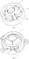
Fig. 1 is a schematic exploded view of a small loudspeaker according toEmbodiment 1 of the present invention; -
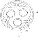
Fig. 2 is a schematic diagram of the frame inFig. 1 after the voice coils are mounted; -
Fig. 3 is a schematic diagram of the small loudspeaker inFig. 1 after being assembled; -
Fig. 4 is a schematic exploded view of a mid-treble loudspeaker according to Embodiment 2 of the present invention; -
Fig. 5 is a schematic diagram of the sound membrane support inFig. 4 after the voice coils are mounted; -
Fig. 6 is a schematic diagram of the mid-treble loudspeaker inFig. 4 after being assembled; - 1 - frame; 10 - magnetic circuit mounting hole; 2 - cone; 20 - voice coil mounting hole; 21 - cone bottom; 22 - tapered edge portion; 3 - input drive mechanism; 31 - voice coil; 310 - lead; 32 - magnetic pole core; 33 - neodymium magnetic steel; 34 - U-yoke; 4 - yoke ring; 5 - audio signal input terminal;
- 1' - sound membrane support; 10' - magnetic circuit mounting hole; 2' - sound membrane; 20' - spherical portion; 21' - yoke ring; 22' - voice coil support; 3' - input drive mechanism; 31' - voice coil; 310' - lead; 32' - magnetic pole core; 33' - neodymium magnetic steel; 34' - U-yoke; 4' - sound amplifying cover; 5' - audio signal input terminal.
- In the following, the preferable embodiments of the present invention are explained in detail combining with the accompanying drawings so that the advantages and features of the present invention can be easily understood by the skilled persons in the art. It should be noted that the explanation on these implementations is to help understanding of the present invention, and is not intended to limit the present invention.
- This embodiment provides a small loudspeaker with multi-input-drives, which is specifically a small loudspeaker without damper. Herein, "multi-input" refers to multiple audio signal inputs, multiple audio signals are input to multiple voice coils, and the multiple voice coils jointly drive the loudspeaker to produce sound. Referring to
Fig. 1 to Fig. 3 , the multi-input-driving loudspeaker comprises aframe 1, a cone 2, and a plurality ofinput driving mechanisms 3. The cone 2 is used to vibrate to produce sound, and is fixed arranged on theframe 1. Eachinput driving mechanism 3 comprises avoice coil 31 and a magnetic circuit assembly for driving thevoice coil 31 to vibrate; wherein, a plurality of magneticcircuit mounting holes 10 are opened on theframe 1, and at most one magnetic circuit assembly is arranged at each magneticcircuit mounting hole 10; a plurality of voicecoil mounting holes 20 are opened on the cone 2, and at most onevoice coil 31 is provided at each voicecoil mounting hole 20. That is, the plurality of input-driving mechanisms is mounted on theframe 1 and the cone 2. There are three or moreinput driving mechanisms 3 to increase the driving energy of the loudspeaker, and the three or moreinput driving mechanisms 3 are arranged at equal intervals along a circle. The cone has a flat-sheet cone bottom 21 that is round as a whole, and the center of the circle coincides with the center of the cone bottom 21, that is, the plurality ofinput driving mechanisms 3 is arranged at equal intervals along the circle of thecone bottom 21. Correspondingly, three or more voicecoil mounting holes 20 are opened on the cone bottom 21, the voicecoil mounting holes 20 are arranged at equal intervals along a circle, and each of the voicecoil mounting holes 20 is provided with onevoice coil 31 so that thevoice coil 31 is connected with the cone bottom 21; theframe 1 is provided with three or more magneticcircuit mounting holes 10, the magneticcircuit mounting holes 10 are arranged at equal intervals along the circle, and each of the magneticcircuit mounting holes 10 is provided with one magnetic circuit assembly. Specifically, as shown inFigs. 1 - 3 , the number of theinput driving mechanisms 3, the voicecoil mounting holes 20 and the magneticcircuit mounting holes 10 are all three, and they are evenly arranged in a ring around the center of thecone bottom 21. - In this embodiment, it is preferable to adopt a cone whose bottom is round as a whole, and the plurality of input-driving mechanisms are arranged in a ring around the center of the bottom of the cone. In some other embodiments, the cone has an oval or rectangular cone bottom, and the plurality of the input-driving mechanisms are arranged linearly or in an array.
- In this embodiment, the
frame 1 is made of plastic using processes such as injection molding, which is easy to form and has a certain strength, and the magneticcircuit mounting holes 10 are through holes that through theframe 1 from top to bottom. The cone 2 further comprises a taperededge portion 22 extending obliquely upwards from the outer edge of the cone bottom 21, and the taperededge portion 22 is arranged in a circle around thecone bottom 21. The cone 2 is made of paper pulp, plastic (such as, PP (polypropylene)), ballistic fiber or aluminum alloy, and the made cone 2 is light in weight, has good damping elasticity and rigidity, high temperature and low temperature resistance, waterproof and mildew proof. In addition, the taperededge portion 22 of the cone 2 is fixedly connected to theframe 1 through ayoke ring 4, which is made of sponge, rubber, or cloth. With the cone 2 with the above-mentioned shape, the directional expansion width is superior to that of the traditional conical loudspeaker, and the height is lower than that of the traditional conical cone 2, which is beneficial to reducing the overall height of the loudspeaker. Each input-drivingmechanism 3 is consisted of avoice coil 31, amagnetic pole core 32, a neodymiummagnetic steel 33, and a U-yoke 34. In each input-drivingmechanism 3, the upper end portion of thevoice coil 31 is fixedly connected to the cone 2 so as to drive the cone 2 to vibrate; thevoice coil 31 passes through the corresponding magneticcircuit mounting hole 10. The U-yoke 34 has an inner cavity and an open upper end, the upper edge of the U-yoke 34 is fixedly connected at the lower surface of the frame 1 adjacent to the magnetic circuit mounting hole 10, and the magnetic circuit mounting hole 10 is in communication with the inner cavity of the U-yoke 34; the magnetic pole core 32 and the neodymium magnetic steel 33 are stacked from top to bottom, and are fixedly arranged in the inner cavity of the U-yoke 34, to form a magnetic circuit assembly; the lower surface of the magnetic pole core 32 closely contacts the upper surface of the neodymium magnetic steel 33; there are gaps between the magnetic pole the core 32 and the inner wall of the U-yoke 34 and between the neodymium magnetic steel 33 and the inner wall of the U-yoke 34, thereby form a magnetic gap surrounding both the magnetic pole core 32 and the neodymium magnetic steel 33, the lower end of the voice coil 31 is inserted into the magnetic gap downward from the magnetic circuit mounting hole 10, there is a gap between the voice coil 31 and the magnetic pole core 32 or the neodymium magnet 33, and there is also a gap between the voice coil 31 and the inner wall of the U-yoke 34, so that the voice coil 31' can move up and down in the magnetic gap. - The magnetic circuit assemblies in this embodiment adopt the aforementioned neodymium magnetic steel, which has the advantages of small volume and light weight. In some other embodiments, the aforementioned neodymium magnetic steel in the magnetic circuit assemblies can be replaced with ferrite magnetic steel, thereby reducing the cost of the magnetic circuit assemblies.
- As shown in
Fig. 2 , multiple pairs of audiosignal input terminals 5 are arranged on an edge of theframe 1, and each pair of audiosignal input terminals 5 is electrically connected to leads of onevoice coil 31. Wherein, each pair of audiosignal input terminals 5 comprises a positive terminal and a negative terminal, one lead of eachvoice coil 31 is electrically connected to the positive terminal of one pair of audiosignal input terminals 5, and another lead is electrically connected to the negative terminal of this pair of audiosignal input terminals 5, to receive the audio signal (analog signal or digital signal) input from the pair of audiosignal input terminal 5. Thus, threevoice coils 31 are simultaneously driven through the four pairs of audiosignal input terminals 5. By providing multiple integrated terminals for audio signal input in theframe 1, the positive and negative leads of eachvoice coil 31 can be connected to the terminals of theframe 1, and this connection method simplifies the manufacture of multi-input-driving loudspeakers, and is also convenient for the connection of audio signal input. - The working principle of the multi-input-driving small loudspeaker is: the audio signals are input to the plurality of voice coils 31 through the audio
signal input terminals 5 on theframe 1, and the plurality ofvoice coils 31 move up and down synchronously under the action of the magnetic circuit assemblies, thereby driving the cone 2 to vibrate to produce sound. The multi-input-driving small loudspeaker of the present invention adopts a cone 2 with a flat-sheet bottom, three or more voicecoil mounting holes 20 are provided on the plane formed by the cone bottom 21, and tightly fitted with three or more voice coils 31, and then the voice coils 31 are tightly fitted with thedampers 33 to form three or more input-drivingmechanisms 3, and by using three or more magnetic circuit assemblies to drive the voice coils 31, and the three ormore voice coils 31 to drive the cone 2, it can not only reduce the height of the product, but also broaden the directivity of the product, and through multiple audio signal inputs, it can reduce the distortion of the product, increase the sensitivity of the loudspeakers, and improve the intelligiblity of the loudspeaker. The use of integrated terminals simplifies the connection of the product and facilitates the connection of audio signal input. - The small loudspeaker structure is ingenious and rational, and through the use of a flat-bottom conical cone structure, the flat-bottom conical cone has a better directivity than traditional loudspeakers; by receiving the audio signal input via three or more voice coils, the original sound reproduction and distortion are better than that of traditional loudspeakers; by adopting a flat-bottom conical cone shape, the height of the cone is lower than that of the traditional conical cone, and the reduction of the height of the cone can also reduce the height of the product; by using an input-driving structure consisted of three or more voice coils and three or more magnetic circuit assemblies, the sensitivity of the small loudspeaker is increased; by closely connecting the flat-bottom conical cone with three or more voice coils, the three or more voice coils are driven through three or more audio signal inputs to move up and down in the U-yoke magnetic circuit to drive the cone to sound.
- This embodiment provides a mid-treble loudspeaker with multi-input-drives, which is specifically a mid-treble loudspeaker without damper. Herein, "multi-input" refers to multiple audio signal inputs, multiple audio signals are input to multiple voice coils, and the multiple voice coils jointly drive the loudspeaker to produce sound. Referring to
Fig. 4 to Fig. 6 , the mid-treble loudspeaker comprises a sound membrane support 1', a sound membrane 2', and a plurality of input driving mechanisms 3'. The sound membrane 2' is used to vibrate to produce sound, and is fixed arranged on the sound membrane support 1'. Each input driving mechanism 3' comprises a voice coil 31' and a magnetic circuit assembly for driving the voice coil 31' to vibrate; wherein, a plurality of magnetic circuit mounting holes 10' are opened on the sound membrane support 1', and at most one magnetic circuit assembly is arranged at each magnetic circuit mounting hole 10'; a lower portion of the sound membrane 2' is fixedly connected with a voice coil support 22', a plurality of voice coil mounting grooves (not shown) are arranged on a lower surface of the voice coil support 22', and at most one voice coil 31' is provided at each voice coil mounting groove. That is, the plurality of input-driving mechanisms are mounted on the sound membrane support 1' and the sound membrane 2'. There are three or more input driving mechanisms 3' to increase the driving energy of the loudspeaker, and the three or more input driving mechanisms 3' are arranged at equal intervals along a circle. The voice coil support 22' has a flat shape that is round as a whole, and the center of the circle coincides with the center of the voice coil support 22', that is, the plurality of input driving mechanisms 3' is arranged at equal intervals along the circumference of the voice coil support 22'. Correspondingly, three or more voice coil mounting grooves are arranged on the lower surface of the voice coil support 22', the voice coil mounting grooves are arranged at equal intervals along the circumference, and each of the voice coil mounting groove is provided with one voice coil 31' so that the voice coil 31' is connected with the voice coil support 22'; three or more magneticcircuit mounting holes 10 are opened on the sound membrane support 1', the magneticcircuit mounting holes 10 are arranged at equal intervals along the circle, and each of the magneticcircuit mounting holes 10 is provided with one magnetic circuit assembly. Specifically, as shown inFig. 4 , the number of the input driving mechanisms 3', the voice coil mounting grooves and the magneticcircuit mounting holes 10 are all three, and they are evenly arranged in a ring around the center of the voice coil support 22'. - In this embodiment, it is preferable to adopt a voice coil support 22' that is round as a whole, and the plurality of input-driving mechanisms 3' are arranged in a ring around the center of the voice coil support 22'. In some other embodiments, the voice coil support 22' is oval or rectangular overall, and the plurality of the input-driving mechanisms 3' are arranged linearly or in an array. The sound membrane 2' has a spherical portion 20' arched upwardly and a yoke ring 21' around the outer edge of the spherical portion 20', the two are integrally formed or fixedly connected. The yoke ring 21' and the voice coil support 22' are fixedly connected, in this embodiment, the yoke ring 21' and the voice coil support 22' are bonded together so as to form a sound cavity between the spherical portion 20' and the voice coil support 22'. The voice coil support 22' is a circular flat sheet, and is fixedly connected below the spherical portion 20' through the yoke ring 21'.
- Each input-driving mechanism 3' specifically is consisted of a voice coil 31', a magnetic pole core 32', a neodymium magnetic steel 33', and a U-yoke 34'. In each input-driving mechanism 3', the upper end portion of the voice coil 31' is fixedly connected to the voice coil support 22' so as to drive the voice coil support 22' and thus the sound membrane 2' connected thereto to vibrate; the voice coil 31' passes through the corresponding magnetic
circuit mounting hole 10. The U-yoke 34' has an inner cavity and an open upper end, the upper edge of the U-yoke 34' is fixedly connected at the lower surface of the sound membrane support 1' adjacent to the magnetic circuit mounting hole 10', and the magnetic circuit mounting hole 10' is in communication with the inner cavity of the U-yoke 34'; the magnetic pole core 32' and the neodymium magnetic steel 33' are stacked from top to bottom, and are fixedly arranged in the inner cavity of the U-yoke 34', to form a magnetic circuit assembly; the lower surface of the magnetic pole core 32' closely contacts the upper surface of the neodymium magnetic steel 33'; there are gaps between the magnetic pole the core 32' and the inner wall of the U-yoke 34' and between the neodymium magnetic steel 33' and the inner wall of the U-yoke 34', thereby form a magnetic gap surrounding both the magnetic pole core 32' and the neodymium magnetic steel 33', the lower end of the voice coil 31' is inserted into the magnetic gap downward from the magnetic circuit mounting hole 10', there is a gap between the voice coil 31' and the magnetic pole core 32' or the neodymium magnet 33', and there is also a gap between the voice coil 31' and the inner wall of the U-yoke 34', so that the voice coil 31' can move up and down in the magnetic gap. - The mid-treble loudspeaker further comprises a sound amplifying cover 4', and the sound amplifying cover 4' is covered on the sound membrane 2' and is fixedly connected on the sound membrane support 1'.
- As shown in
Fig. 5 , multiple pairs of audio signal input terminals 5' are arranged on an edge portion of the sound membrane support 1', and each pair of audio signal input terminals 5' is electrically connected to leads of one voice coil 31'. Wherein, each pair of audio signal input terminals 5' comprises a positive terminal and a negative terminal, one lead of each voice coil 31' is electrically connected to the positive terminal of one pair of audio signal input terminals 5', and another lead is electrically connected to the negative terminal of this pair of audio signal input terminals 5', to receive the audio signal (analog signal or digital signal) input from the pair of audio signal input terminal 5'. Thus, three voice coils 31' are simultaneously driven through the four pairs of audio signal input terminals 5'. By providing multiple integrated terminals for audio signal input in the sound membrane support 1', the positive and negative leads of each voice coil 31' can be connected to the terminals of the sound membrane support 1', and this connection method simplifies the manufacture of multi-input-driving loudspeakers, and is also convenient for the connection of audio signal input. - The working principle of the multi-input-driving mid-treble loudspeaker is: the audio signals are input to the plurality of voice coils 31' through the audio signal input terminals 5' on the sound membrane support 1', and the plurality of voice coils 31' move up and down synchronously under the action of the magnetic circuit assemblies, thereby driving the voice coil support 22' and the sound membrane 2' connected thereto to vibrate to produce sound. In the mid-treble loudspeaker with multi-input-drives of the present invention, the sound membrane 2' is driven by three or more voice coils 31', which reduces the distortion of the product, increases the sensitivity of the loudspeaker, and improves the intelligiblity of the loudspeaker. The use of integrated terminals simplifies the connection of the product and facilitates the connection of audio signal input.
- The embodiments described above are only for illustrating the technical concepts and features of the present invention, are preferred embodiments, and are intended to make those skilled in the art being able to understand the present invention and thereby implement it, and should not be concluded to limit the protective scope of this invention.
Claims (19)
- A small loudspeaker with multi-input-drives, comprising a frame, and a cone arranged on the frame, is characterized in that, the small loudspeaker further comprises a plurality of input driving mechanisms, each of the input driving mechanisms comprises a voice coil and a magnetic circuit assembly for driving the voice coil to vibrate, each of the magnetic circuit assemblies comprises a U-yoke having an inner cavity, a magnetic steel and a magnetic pole core arranged within the U-yoke, a magnetic gap is formed between an inner wall of the U-yoke and the magnetic steel or the magnetic pole core, the voice coil is inserted in the magnetic gap and capable of moving in an up-and-down direction; a plurality of magnetic circuit mounting holes are opened on the frame, and at most one U-yoke is arranged below each magnetic circuit mounting hole, and the voice coils respectively pass through the corresponding magnetic circuit mounting holes, and lower portions of the voice coils are respectively inserted into the magnetic gaps; the cone has a flat-sheet cone bottom, a plurality of voice coil mounting holes are opened on the cone bottom, and at most one voice coil is arranged at each voice coil mounting hole.
- The small loudspeaker according to claim 1, is characterized in that, there are three or more input driving mechanisms, and the three or more input driving mechanisms are arranged at equal intervals along a circle.
- The small loudspeaker according to claim 2, is characterized in that, the cone bottom is round as a whole, and a center of the circle coincides with a center of the cone bottom.
- The small loudspeaker according to claim 2, is characterized in that, three or more voice coil mounting holes are arranged on the cone bottom, the voice coil mounting holes are arranged at equal intervals along the circle, and each of the voice coil mounting holes is provided with one voice coil to connect the voice coil to the cone bottom; three or more magnetic circuit mounting holes are opened on the frame, the magnetic circuit mounting holes are arranged at equal intervals along the circle, and each of the magnetic circuit mounting holes is provided with one magnetic circuit assembly.
- The small loudspeaker according to claim 1, is characterized in that, the cone further comprises a tapered edge portion extending obliquely upwards from an outer edge of the cone bottom, and the tapered edge portion is fixedly connected to the frame through a yoke ring.
- The small loudspeaker according to claim 1, is characterized in that, each of the magnetic circuit assemblies is composed of a U-yoke, and a magnetic pole core and a neodymium magnetic steel arranged within the U-yoke, and a lower surface of the magnetic pole core closely contacts an upper surface of the neodymium magnetic steel.
- The small loudspeaker according to claim 1, is characterized in that, an upper edge of the U-yoke is fixedly connected to a lower surface of the frame.
- The small loudspeaker according to claim 1, is characterized in that, multiple pairs of audio signal input terminals are arranged on an edge of the frame, and each pair of the audio signal input terminals is electrically connected to leads of one voice coil.
- The small loudspeaker according to claim 1, is characterized in that, the plurality of input driving mechanisms are arranged in a circular, linear, or an array.
- A mid-treble loudspeaker with multi-input-drives, comprising a sound membrane support, and a sound membrane arranged on the sound membrane support, is characterized in that, the mid-treble loudspeaker further comprises a plurality of input driving mechanisms, each of the input driving mechanisms comprises a voice coil and a magnetic circuit assembly for driving the voice coil to vibrate, each of the magnetic circuit assemblies comprises a U-yoke having an inner cavity, a magnetic steel and a magnetic pole core arranged within the U-yoke, a magnetic gap is formed between an inner wall of the U-yoke and the magnetic steel or the magnetic pole core, the voice coil is inserted in the magnetic gap and capable of moving in an up-and-down direction; a plurality of magnetic circuit mounting holes are opened on the sound membrane support, and at most one U-yoke is arranged below each magnetic circuit mounting hole, and the voice coils respectively pass through the corresponding magnetic circuit mounting holes, and lower portions of the voice coils are respectively inserted into the magnetic gaps; a lower portion of the sound membrane is fixedly connected with a flat-sheet voice coil support, a plurality of voice coil mounting grooves are opened on the voice coil support, and at most one voice coil is arranged at each voice coil mounting groove.
- The mid-treble loudspeaker according to claim 10, is characterized in that, there are three or more input driving mechanisms, and the three or more input driving mechanisms are arranged at equal intervals along a circle.
- The mid-treble loudspeaker according to claim 11, is characterized in that, the voice coil support is round as a whole, and a center of the circle coincides with a center of the voice coil support.
- The mid-treble loudspeaker according to claim 11, is characterized in that, three or more voice coil mounting grooves are arranged on the voice coil support, the voice coil mounting grooves are arranged at equal intervals along the circle, and each of the voice coil mounting grooves is provided with one voice coil to connect the voice coil to the voice coil support; three or more magnetic circuit mounting holes are opened on the sound membrane support, the magnetic circuit mounting holes are arranged at equal intervals along the circle, and each of the magnetic circuit mounting holes is provided with one magnetic circuit assembly.
- The mid-treble loudspeaker according to claim 10, is characterized in that, the sound membrane has a spherical portion arched upwardly and a yoke ring around an outer edge of the spherical portion, and the yoke ring and the voice coil support are fixedly connected.
- The mid-treble loudspeaker according to claim 1, is characterized in that, the mid-treble loudspeaker further comprises a sound amplifying cover, and the sound amplifying cover is covered on the sound membrane.
- The mid-treble loudspeaker according to claim 10, is characterized in that, an upper edge of the U-yoke is fixedly connected to a lower surface of the sound membrane support.
- The mid-treble loudspeaker according to claim 10, is characterized in that, each magnetic circuit assembly is composed of a U-yoke, and a magnetic pole core and a neodymium magnetic steel arranged within the U-yoke, and a lower surface of the magnetic pole core closely contacts an upper surface of the neodymium magnetic steel.
- The mid-treble loudspeaker according to claim 10, is characterized in that, multiple pairs of audio signal input terminals are arranged on an edge of the sound membrane support, and each pair of the audio signal input terminals is electrically connected to leads of one voice coil.
- The mid-treble loudspeaker according to claim 10, is characterized in that, the plurality of input driving mechanisms are arranged in circular, linear, or an array.
Applications Claiming Priority (2)
| Application Number | Priority Date | Filing Date | Title |
|---|---|---|---|
| CN201910634995.XA CN110248297B (en) | 2019-07-15 | 2019-07-15 | A small loudspeaker and mid-high frequency loudspeaker driven by multiple input channels |
| PCT/CN2019/112651 WO2021007982A1 (en) | 2019-07-15 | 2019-10-23 | Multi-path input-driving small loudspeaker and mid-treble loudspeaker |
Publications (3)
| Publication Number | Publication Date |
|---|---|
| EP4002880A1 true EP4002880A1 (en) | 2022-05-25 |
| EP4002880A4 EP4002880A4 (en) | 2023-08-30 |
| EP4002880B1 EP4002880B1 (en) | 2025-12-10 |
Family
ID=67892176
Family Applications (1)
| Application Number | Title | Priority Date | Filing Date |
|---|---|---|---|
| EP19938033.8A Active EP4002880B1 (en) | 2019-07-15 | 2019-10-23 | Multi-path input-driving small loudspeaker and mid-treble loudspeaker |
Country Status (5)
| Country | Link |
|---|---|
| US (1) | US11997467B2 (en) |
| EP (1) | EP4002880B1 (en) |
| JP (1) | JP7466578B2 (en) |
| CN (2) | CN110248297B (en) |
| WO (1) | WO2021007982A1 (en) |
Families Citing this family (4)
| Publication number | Priority date | Publication date | Assignee | Title |
|---|---|---|---|---|
| CN110248297B (en) * | 2019-07-15 | 2024-11-05 | 苏州茹声电子有限公司 | A small loudspeaker and mid-high frequency loudspeaker driven by multiple input channels |
| CN212752626U (en) * | 2020-09-02 | 2021-03-19 | 苏州上声电子股份有限公司 | A small speaker with two cones |
| CN212936188U (en) * | 2020-09-02 | 2021-04-09 | 苏州上声电子股份有限公司 | A dual-cone speaker |
| CN112073880B (en) | 2020-09-02 | 2025-04-08 | 苏州上声电子股份有限公司 | Small-sized loudspeaker with multiple sound basins |
Family Cites Families (21)
| Publication number | Priority date | Publication date | Assignee | Title |
|---|---|---|---|---|
| US3509290A (en) * | 1966-05-03 | 1970-04-28 | Nippon Musical Instruments Mfg | Flat-plate type loudspeaker with frame mounted drivers |
| JPS5525285A (en) * | 1978-08-14 | 1980-02-22 | Sony Corp | Speaker |
| JPS5850581U (en) * | 1981-09-30 | 1983-04-05 | 赤井電機株式会社 | convex speaker |
| JPS5811799B2 (en) * | 1981-12-10 | 1983-03-04 | ソニー株式会社 | speaker |
| JPS6372992U (en) * | 1986-10-31 | 1988-05-16 | ||
| JPH08154296A (en) * | 1994-11-28 | 1996-06-11 | Matsushita Electric Ind Co Ltd | Slim rectangular speaker |
| US7450729B2 (en) * | 2003-04-09 | 2008-11-11 | Harman International Industries, Incorporated | Low-profile transducer |
| US8130994B2 (en) * | 2008-06-17 | 2012-03-06 | Harman International Industries, Incorporated | Waveguide |
| CN101860783B (en) * | 2009-10-13 | 2013-10-30 | 东莞凡振工业电子有限公司 | Thin-type loudspeaker |
| CN102984609A (en) * | 2012-11-27 | 2013-03-20 | 无锡杰夫电声有限公司 | Multi-point excitation source loudspeaker sound box |
| CN203352789U (en) * | 2013-07-16 | 2013-12-18 | 揭阳市天籁高科电子有限公司 | Combination magnetic circuit structure dynamic speaker |
| CN104754477A (en) * | 2015-03-23 | 2015-07-01 | 歌尔声学股份有限公司 | Loudspeaker |
| CN204733375U (en) * | 2015-06-29 | 2015-10-28 | 歌尔声学股份有限公司 | Loud speaker |
| NL2017514B1 (en) * | 2016-09-22 | 2018-03-29 | Univ Delft Tech | Loudspeaker unit with multiple drive units |
| CN106341761A (en) * | 2016-12-05 | 2017-01-18 | 陈新得 | Loudspeaker with multipath magnetic circuit structure |
| EP3355590A1 (en) * | 2017-01-26 | 2018-08-01 | Vestel Elektronik Sanayi ve Ticaret A.S. | Loudspeaker, apparatus comprising the same, and method of operating a loudspeaker |
| CN208079377U (en) * | 2017-11-23 | 2018-11-09 | 苏州东立电子有限公司 | The more magnetic structure loud speakers of double voice coil |
| CN109068247A (en) * | 2018-08-07 | 2018-12-21 | 张永春 | Multiple engine array system and loudspeaker |
| CN208798193U (en) * | 2018-08-16 | 2019-04-26 | 广州市拓进数码科技有限公司 | coaxial horn |
| CN210053568U (en) * | 2019-07-15 | 2020-02-11 | 苏州茹声电子有限公司 | Multi-channel input driven small-sized loudspeaker and medium-high-sound loudspeaker |
| CN110248297B (en) * | 2019-07-15 | 2024-11-05 | 苏州茹声电子有限公司 | A small loudspeaker and mid-high frequency loudspeaker driven by multiple input channels |
-
2019
- 2019-07-15 CN CN201910634995.XA patent/CN110248297B/en active Active
- 2019-07-15 CN CN202411631853.5A patent/CN119729304A/en active Pending
- 2019-10-23 WO PCT/CN2019/112651 patent/WO2021007982A1/en not_active Ceased
- 2019-10-23 EP EP19938033.8A patent/EP4002880B1/en active Active
- 2019-10-23 US US17/623,287 patent/US11997467B2/en active Active
- 2019-10-23 JP JP2021578067A patent/JP7466578B2/en active Active
Also Published As
| Publication number | Publication date |
|---|---|
| EP4002880B1 (en) | 2025-12-10 |
| JP7466578B2 (en) | 2024-04-12 |
| US20220369040A1 (en) | 2022-11-17 |
| CN110248297B (en) | 2024-11-05 |
| EP4002880A4 (en) | 2023-08-30 |
| WO2021007982A1 (en) | 2021-01-21 |
| JP2022541392A (en) | 2022-09-26 |
| US11997467B2 (en) | 2024-05-28 |
| CN110248297A (en) | 2019-09-17 |
| CN119729304A (en) | 2025-03-28 |
Similar Documents
| Publication | Publication Date | Title |
|---|---|---|
| EP4002879B1 (en) | Multiple-input driven loudspeaker | |
| EP3996388B1 (en) | Multi-input driven loudspeaker | |
| EP4002880B1 (en) | Multi-path input-driving small loudspeaker and mid-treble loudspeaker | |
| US12457444B2 (en) | Dual-cone small loudspeaker | |
| US12302081B2 (en) | Multi-input-driving loudspeaker | |
| US20240298116A1 (en) | Dual-cone speaker | |
| CN210053568U (en) | Multi-channel input driven small-sized loudspeaker and medium-high-sound loudspeaker | |
| CN210053561U (en) | Loudspeaker driven by multipath input | |
| US12520084B2 (en) | Multi-cone small speaker |
Legal Events
| Date | Code | Title | Description |
|---|---|---|---|
| STAA | Information on the status of an ep patent application or granted ep patent |
Free format text: STATUS: THE INTERNATIONAL PUBLICATION HAS BEEN MADE |
|
| PUAI | Public reference made under article 153(3) epc to a published international application that has entered the european phase |
Free format text: ORIGINAL CODE: 0009012 |
|
| STAA | Information on the status of an ep patent application or granted ep patent |
Free format text: STATUS: REQUEST FOR EXAMINATION WAS MADE |
|
| 17P | Request for examination filed |
Effective date: 20211229 |
|
| AK | Designated contracting states |
Kind code of ref document: A1 Designated state(s): AL AT BE BG CH CY CZ DE DK EE ES FI FR GB GR HR HU IE IS IT LI LT LU LV MC MK MT NL NO PL PT RO RS SE SI SK SM TR |
|
| DAV | Request for validation of the european patent (deleted) | ||
| DAX | Request for extension of the european patent (deleted) | ||
| A4 | Supplementary search report drawn up and despatched |
Effective date: 20230727 |
|
| RIC1 | Information provided on ipc code assigned before grant |
Ipc: H04R 9/06 20060101ALI20230721BHEP Ipc: H04R 9/02 20060101AFI20230721BHEP |
|
| GRAP | Despatch of communication of intention to grant a patent |
Free format text: ORIGINAL CODE: EPIDOSNIGR1 |
|
| STAA | Information on the status of an ep patent application or granted ep patent |
Free format text: STATUS: GRANT OF PATENT IS INTENDED |
|
| INTG | Intention to grant announced |
Effective date: 20250627 |
|
| GRAS | Grant fee paid |
Free format text: ORIGINAL CODE: EPIDOSNIGR3 |
|
| GRAA | (expected) grant |
Free format text: ORIGINAL CODE: 0009210 |
|
| STAA | Information on the status of an ep patent application or granted ep patent |
Free format text: STATUS: THE PATENT HAS BEEN GRANTED |
|
| AK | Designated contracting states |
Kind code of ref document: B1 Designated state(s): AL AT BE BG CH CY CZ DE DK EE ES FI FR GB GR HR HU IE IS IT LI LT LU LV MC MK MT NL NO PL PT RO RS SE SI SK SM TR |
|
| REG | Reference to a national code |
Ref country code: CH Ref legal event code: F10 Free format text: ST27 STATUS EVENT CODE: U-0-0-F10-F00 (AS PROVIDED BY THE NATIONAL OFFICE) Effective date: 20251210 Ref country code: GB Ref legal event code: FG4D |
|
| REG | Reference to a national code |
Ref country code: DE Ref legal event code: R096 Ref document number: 602019079193 Country of ref document: DE |
|
| REG | Reference to a national code |
Ref country code: IE Ref legal event code: FG4D |
|
| P01 | Opt-out of the competence of the unified patent court (upc) registered |
Free format text: CASE NUMBER: UPC_APP_0016339_4002880/2025 Effective date: 20251209 |
|
| PG25 | Lapsed in a contracting state [announced via postgrant information from national office to epo] |
Ref country code: ES Free format text: LAPSE BECAUSE OF FAILURE TO SUBMIT A TRANSLATION OF THE DESCRIPTION OR TO PAY THE FEE WITHIN THE PRESCRIBED TIME-LIMIT Effective date: 20251210 |
|
| REG | Reference to a national code |
Ref country code: LT Ref legal event code: MG9D |
|
| PG25 | Lapsed in a contracting state [announced via postgrant information from national office to epo] |
Ref country code: NO Free format text: LAPSE BECAUSE OF FAILURE TO SUBMIT A TRANSLATION OF THE DESCRIPTION OR TO PAY THE FEE WITHIN THE PRESCRIBED TIME-LIMIT Effective date: 20260310 |
|
| PG25 | Lapsed in a contracting state [announced via postgrant information from national office to epo] |
Ref country code: FI Free format text: LAPSE BECAUSE OF FAILURE TO SUBMIT A TRANSLATION OF THE DESCRIPTION OR TO PAY THE FEE WITHIN THE PRESCRIBED TIME-LIMIT Effective date: 20251210 Ref country code: HR Free format text: LAPSE BECAUSE OF FAILURE TO SUBMIT A TRANSLATION OF THE DESCRIPTION OR TO PAY THE FEE WITHIN THE PRESCRIBED TIME-LIMIT Effective date: 20251210 |
|
| REG | Reference to a national code |
Ref country code: NL Ref legal event code: MP Effective date: 20251210 |
|
| PG25 | Lapsed in a contracting state [announced via postgrant information from national office to epo] |
Ref country code: RS Free format text: LAPSE BECAUSE OF FAILURE TO SUBMIT A TRANSLATION OF THE DESCRIPTION OR TO PAY THE FEE WITHIN THE PRESCRIBED TIME-LIMIT Effective date: 20260310 |
|
| PG25 | Lapsed in a contracting state [announced via postgrant information from national office to epo] |
Ref country code: LV Free format text: LAPSE BECAUSE OF FAILURE TO SUBMIT A TRANSLATION OF THE DESCRIPTION OR TO PAY THE FEE WITHIN THE PRESCRIBED TIME-LIMIT Effective date: 20251210 |
|
| PG25 | Lapsed in a contracting state [announced via postgrant information from national office to epo] |
Ref country code: BG Free format text: LAPSE BECAUSE OF FAILURE TO SUBMIT A TRANSLATION OF THE DESCRIPTION OR TO PAY THE FEE WITHIN THE PRESCRIBED TIME-LIMIT Effective date: 20251210 |
|
| REG | Reference to a national code |
Ref country code: AT Ref legal event code: MK05 Ref document number: 1867429 Country of ref document: AT Kind code of ref document: T Effective date: 20251210 |
|
| PG25 | Lapsed in a contracting state [announced via postgrant information from national office to epo] |
Ref country code: NL Free format text: LAPSE BECAUSE OF FAILURE TO SUBMIT A TRANSLATION OF THE DESCRIPTION OR TO PAY THE FEE WITHIN THE PRESCRIBED TIME-LIMIT Effective date: 20251210 |
|
| PG25 | Lapsed in a contracting state [announced via postgrant information from national office to epo] |
Ref country code: LT Free format text: LAPSE BECAUSE OF FAILURE TO SUBMIT A TRANSLATION OF THE DESCRIPTION OR TO PAY THE FEE WITHIN THE PRESCRIBED TIME-LIMIT Effective date: 20251210 |
|
| PG25 | Lapsed in a contracting state [announced via postgrant information from national office to epo] |
Ref country code: SM Free format text: LAPSE BECAUSE OF FAILURE TO SUBMIT A TRANSLATION OF THE DESCRIPTION OR TO PAY THE FEE WITHIN THE PRESCRIBED TIME-LIMIT Effective date: 20251210 |
|
| PG25 | Lapsed in a contracting state [announced via postgrant information from national office to epo] |
Ref country code: PL Free format text: LAPSE BECAUSE OF FAILURE TO SUBMIT A TRANSLATION OF THE DESCRIPTION OR TO PAY THE FEE WITHIN THE PRESCRIBED TIME-LIMIT Effective date: 20251210 |
|
| PG25 | Lapsed in a contracting state [announced via postgrant information from national office to epo] |
Ref country code: AT Free format text: LAPSE BECAUSE OF FAILURE TO SUBMIT A TRANSLATION OF THE DESCRIPTION OR TO PAY THE FEE WITHIN THE PRESCRIBED TIME-LIMIT Effective date: 20251210 |
|
| PG25 | Lapsed in a contracting state [announced via postgrant information from national office to epo] |
Ref country code: EE Free format text: LAPSE BECAUSE OF FAILURE TO SUBMIT A TRANSLATION OF THE DESCRIPTION OR TO PAY THE FEE WITHIN THE PRESCRIBED TIME-LIMIT Effective date: 20251210 |
|
| PG25 | Lapsed in a contracting state [announced via postgrant information from national office to epo] |
Ref country code: PT Free format text: LAPSE BECAUSE OF FAILURE TO SUBMIT A TRANSLATION OF THE DESCRIPTION OR TO PAY THE FEE WITHIN THE PRESCRIBED TIME-LIMIT Effective date: 20260410 Ref country code: IS Free format text: LAPSE BECAUSE OF FAILURE TO SUBMIT A TRANSLATION OF THE DESCRIPTION OR TO PAY THE FEE WITHIN THE PRESCRIBED TIME-LIMIT Effective date: 20260410 |
|
| PG25 | Lapsed in a contracting state [announced via postgrant information from national office to epo] |
Ref country code: CZ Free format text: LAPSE BECAUSE OF FAILURE TO SUBMIT A TRANSLATION OF THE DESCRIPTION OR TO PAY THE FEE WITHIN THE PRESCRIBED TIME-LIMIT Effective date: 20251210 |
|
| PG25 | Lapsed in a contracting state [announced via postgrant information from national office to epo] |
Ref country code: SK Free format text: LAPSE BECAUSE OF FAILURE TO SUBMIT A TRANSLATION OF THE DESCRIPTION OR TO PAY THE FEE WITHIN THE PRESCRIBED TIME-LIMIT Effective date: 20251210 |
|
| PG25 | Lapsed in a contracting state [announced via postgrant information from national office to epo] |
Ref country code: SE Free format text: LAPSE BECAUSE OF FAILURE TO SUBMIT A TRANSLATION OF THE DESCRIPTION OR TO PAY THE FEE WITHIN THE PRESCRIBED TIME-LIMIT Effective date: 20251210 |