EP4002879A1 - Multiple-input driven loudspeaker - Google Patents
Multiple-input driven loudspeaker Download PDFInfo
- Publication number
- EP4002879A1 EP4002879A1 EP19937763.1A EP19937763A EP4002879A1 EP 4002879 A1 EP4002879 A1 EP 4002879A1 EP 19937763 A EP19937763 A EP 19937763A EP 4002879 A1 EP4002879 A1 EP 4002879A1
- Authority
- EP
- European Patent Office
- Prior art keywords
- voice coil
- main
- input
- cone
- driving mechanism
- Prior art date
- Legal status (The legal status is an assumption and is not a legal conclusion. Google has not performed a legal analysis and makes no representation as to the accuracy of the status listed.)
- Granted
Links
Images


Classifications
-
- H—ELECTRICITY
- H04—ELECTRIC COMMUNICATION TECHNIQUE
- H04R—LOUDSPEAKERS, MICROPHONES, GRAMOPHONE PICK-UPS OR LIKE ACOUSTIC ELECTROMECHANICAL TRANSDUCERS; ELECTRIC HEARING AIDS; PUBLIC ADDRESS SYSTEMS
- H04R9/00—Transducers of moving-coil, moving-strip, or moving-wire type
- H04R9/06—Loudspeakers
- H04R9/063—Loudspeakers using a plurality of acoustic drivers
-
- H—ELECTRICITY
- H04—ELECTRIC COMMUNICATION TECHNIQUE
- H04R—LOUDSPEAKERS, MICROPHONES, GRAMOPHONE PICK-UPS OR LIKE ACOUSTIC ELECTROMECHANICAL TRANSDUCERS; ELECTRIC HEARING AIDS; PUBLIC ADDRESS SYSTEMS
- H04R9/00—Transducers of moving-coil, moving-strip, or moving-wire type
- H04R9/02—Details
- H04R9/04—Construction, mounting, or centering of coil
- H04R9/046—Construction
-
- H—ELECTRICITY
- H04—ELECTRIC COMMUNICATION TECHNIQUE
- H04R—LOUDSPEAKERS, MICROPHONES, GRAMOPHONE PICK-UPS OR LIKE ACOUSTIC ELECTROMECHANICAL TRANSDUCERS; ELECTRIC HEARING AIDS; PUBLIC ADDRESS SYSTEMS
- H04R7/00—Diaphragms for electromechanical transducers; Cones
- H04R7/02—Diaphragms for electromechanical transducers; Cones characterised by the construction
- H04R7/12—Non-planar diaphragms or cones
-
- H—ELECTRICITY
- H04—ELECTRIC COMMUNICATION TECHNIQUE
- H04R—LOUDSPEAKERS, MICROPHONES, GRAMOPHONE PICK-UPS OR LIKE ACOUSTIC ELECTROMECHANICAL TRANSDUCERS; ELECTRIC HEARING AIDS; PUBLIC ADDRESS SYSTEMS
- H04R7/00—Diaphragms for electromechanical transducers; Cones
- H04R7/16—Mounting or tensioning of diaphragms or cones
- H04R7/18—Mounting or tensioning of diaphragms or cones at the periphery
- H04R7/20—Securing diaphragm or cone resiliently to support by flexible material, springs, cords, or strands
-
- H—ELECTRICITY
- H04—ELECTRIC COMMUNICATION TECHNIQUE
- H04R—LOUDSPEAKERS, MICROPHONES, GRAMOPHONE PICK-UPS OR LIKE ACOUSTIC ELECTROMECHANICAL TRANSDUCERS; ELECTRIC HEARING AIDS; PUBLIC ADDRESS SYSTEMS
- H04R9/00—Transducers of moving-coil, moving-strip, or moving-wire type
- H04R9/02—Details
-
- H—ELECTRICITY
- H04—ELECTRIC COMMUNICATION TECHNIQUE
- H04R—LOUDSPEAKERS, MICROPHONES, GRAMOPHONE PICK-UPS OR LIKE ACOUSTIC ELECTROMECHANICAL TRANSDUCERS; ELECTRIC HEARING AIDS; PUBLIC ADDRESS SYSTEMS
- H04R9/00—Transducers of moving-coil, moving-strip, or moving-wire type
- H04R9/02—Details
- H04R9/025—Magnetic circuit
- H04R9/027—Air gaps using a magnetic fluid
-
- H—ELECTRICITY
- H04—ELECTRIC COMMUNICATION TECHNIQUE
- H04R—LOUDSPEAKERS, MICROPHONES, GRAMOPHONE PICK-UPS OR LIKE ACOUSTIC ELECTROMECHANICAL TRANSDUCERS; ELECTRIC HEARING AIDS; PUBLIC ADDRESS SYSTEMS
- H04R9/00—Transducers of moving-coil, moving-strip, or moving-wire type
- H04R9/06—Loudspeakers
-
- H—ELECTRICITY
- H04—ELECTRIC COMMUNICATION TECHNIQUE
- H04R—LOUDSPEAKERS, MICROPHONES, GRAMOPHONE PICK-UPS OR LIKE ACOUSTIC ELECTROMECHANICAL TRANSDUCERS; ELECTRIC HEARING AIDS; PUBLIC ADDRESS SYSTEMS
- H04R2209/00—Details of transducers of the moving-coil, moving-strip, or moving-wire type covered by H04R9/00 but not provided for in any of its subgroups
-
- H—ELECTRICITY
- H04—ELECTRIC COMMUNICATION TECHNIQUE
- H04R—LOUDSPEAKERS, MICROPHONES, GRAMOPHONE PICK-UPS OR LIKE ACOUSTIC ELECTROMECHANICAL TRANSDUCERS; ELECTRIC HEARING AIDS; PUBLIC ADDRESS SYSTEMS
- H04R2209/00—Details of transducers of the moving-coil, moving-strip, or moving-wire type covered by H04R9/00 but not provided for in any of its subgroups
- H04R2209/041—Voice coil arrangements comprising more than one voice coil unit on the same bobbin
-
- H—ELECTRICITY
- H04—ELECTRIC COMMUNICATION TECHNIQUE
- H04R—LOUDSPEAKERS, MICROPHONES, GRAMOPHONE PICK-UPS OR LIKE ACOUSTIC ELECTROMECHANICAL TRANSDUCERS; ELECTRIC HEARING AIDS; PUBLIC ADDRESS SYSTEMS
- H04R2400/00—Loudspeakers
- H04R2400/11—Aspects regarding the frame of loudspeaker transducers
-
- H—ELECTRICITY
- H04—ELECTRIC COMMUNICATION TECHNIQUE
- H04R—LOUDSPEAKERS, MICROPHONES, GRAMOPHONE PICK-UPS OR LIKE ACOUSTIC ELECTROMECHANICAL TRANSDUCERS; ELECTRIC HEARING AIDS; PUBLIC ADDRESS SYSTEMS
- H04R7/00—Diaphragms for electromechanical transducers; Cones
- H04R7/02—Diaphragms for electromechanical transducers; Cones characterised by the construction
- H04R7/04—Plane diaphragms
-
- H—ELECTRICITY
- H04—ELECTRIC COMMUNICATION TECHNIQUE
- H04R—LOUDSPEAKERS, MICROPHONES, GRAMOPHONE PICK-UPS OR LIKE ACOUSTIC ELECTROMECHANICAL TRANSDUCERS; ELECTRIC HEARING AIDS; PUBLIC ADDRESS SYSTEMS
- H04R9/00—Transducers of moving-coil, moving-strip, or moving-wire type
- H04R9/02—Details
- H04R9/04—Construction, mounting, or centering of coil
- H04R9/041—Centering
- H04R9/043—Inner suspension or damper, e.g. spider
-
- H—ELECTRICITY
- H04—ELECTRIC COMMUNICATION TECHNIQUE
- H04R—LOUDSPEAKERS, MICROPHONES, GRAMOPHONE PICK-UPS OR LIKE ACOUSTIC ELECTROMECHANICAL TRANSDUCERS; ELECTRIC HEARING AIDS; PUBLIC ADDRESS SYSTEMS
- H04R9/00—Transducers of moving-coil, moving-strip, or moving-wire type
- H04R9/02—Details
- H04R9/04—Construction, mounting, or centering of coil
- H04R9/045—Mounting
Definitions
- the present invention relates to the loudspeaker field, in particular to a multi-input-driving loudspeaker.
- Existing loudspeakers generally adopt a structure comprising a conical cone (made of paper, PP and other materials) combined with a damper, the middle of the conical cone and the damper is respectively provided with a central hole, the damper is arranged below the conical cone, a single signal input voice coil passes through the central holes of the damper and the conical cone, and the conical cone and the damper are glued on the outer wall of the voice coil respectively to form a loudspeaker vibration system.
- This kind of loudspeaker can only be used for single signal input and has limitations on the reproduction of the original sound.
- one of the current improvements is to adopt a structure comprising a conical cone combined with a damper, central holes are opened in the middle of the cone and the damper, respectively, the damper is arranged below the conical cone, and the voice coil is changed from the single signal input mode to a multiple signal input mode and passes through the central holes of the damper and the conical cone, wherein the voice coil is formed by stacking multiple sets of coils from the inside to the outside, and the conical cone and the damper are glued on the outer wall of the voice coil respectively to form a loudspeaker vibration system.
- This kind of loudspeaker can be used for multiple signal input.
- this type of loudspeaker has multiple sets of coils wound on one voice coil, winding multiple sets of coils into one voice coil increases the weight of the voice coil, and when the voice coil drives the cone, the sensitivity of the loudspeaker will be lost.
- the present invention provides a multi-input-driving loudspeaker, which reduces the distortion of a loudspeaker, increases the sensitivity of a loudspeaker, improves the intelligiblity of a loudspeaker, meanwhile has a compact structure.
- multi-input refers to multiple audio signal inputs
- multi-input driving refers to multiple audio signals input to multiple voice coils, and the multiple voice coils jointly drive the loudspeaker to produce sound.
- each of the secondary input-driving mechanism further comprises an elastic dust ring, and the dust ring is sleeved on the voice coil.
- an upper end of the dust ring is connected to the cone, and a lower end of the dust ring is connected to the frame.
- the dust ring is a corrugated hose.
- the plurality of secondary input-driving mechanisms surrounds the main input-driving mechanism or is located on both sides of the main input-driving mechanism.
- the cone has a flat-sheet cone bottom, the main voice coil mounting hole and the secondary voice coil mounting holes are opened on the cone bottom.
- there are three or more secondary input driving mechanisms and the three or more secondary input-driving mechanisms are arranged at equal intervals around the main input-driving mechanism along a circle, the three or more secondary voice coil mounting holes are arranged at intervals along the circle around a center line of the main voice coil mounting hole, and the three or more secondary magnetic circuit mounting holes are arranged at equal intervals along the circle around a center line of the central hole.
- the cone has a flat-sheet cone bottom that is round as a whole, a center of the circle coincides with a center of the cone bottom, and the main voice coil mounting hole and the cone bottom are arranged concentrically.
- the cone further comprises a tapered edge portion extending obliquely upwards from an outer edge of the cone bottom, and the tapered edge portion is fixedly connected to the frame through a yoke ring.
- the main input-driving mechanism further comprises a damper, and the main voice coil passes through the damper and capable of moving in an up-and-down direction.
- the frame is provided with a flange surrounding the central hole, and the damper and the flange cooperate with each other so that the damper is clamped into the flange.
- the front panel is fixedly connected to a lower portion of the frame.
- the secondary magnetic circuit assembly comprises a U-yoke having an inner cavity, a second magnetic steel and a magnetic pole core arranged within the U-yoke, a secondary magnetic gap is formed between the second magnetic steel and the magnetic pole core and an inner wall of the U-yoke, the secondary voice coil is inserted in the secondary magnetic gap and capable of moving in an up-and-down direction, and an upper edge of the U-yoke is fixedly connected to the secondary magnetic circuit mounting hole of the frame.
- each of the main input-driving mechanism and the secondary input-driving mechanisms comprises a dust cover, and each of main voice coil mounting hole and the secondary voice coil mounting holes is covered with one dust cover.
- the multi-input-driving loudspeaker of the present invention drives the cone vibration to occur through the combination of one main input-driving mechanism and four secondary input-driving mechanisms, which increases the driving energy of the loudspeaker; a plurality of secondary input-driving mechanisms surrounding around the main input-driving mechanism makes the overall structure more compact on the premise of increasing the driving energy of the loudspeaker and avoids excessive volume.
- the structure is ingenious and rational, and by using a plurality of voice coils to drive the cone, and having audio signal inputs, the product distortion is reduced, the sensitivity of a loudspeaker is increased, and the intelligiblity of a loudspeaker is improved.
- multi-input refers to multiple audio signal inputs, multiple audio signals are input to multiple voice coils, and the multiple voice coils jointly drive the loudspeaker to produce sound.
- the loudspeaker comprises a frame 1, a cone 2 arranged on the frame 1, and the loudspeaker further comprises a main input driving mechanism 3 and a plurality of secondary input driving mechanisms 4.
- the main input-driving mechanism 3 is arranged between the plurality of secondary input-driving mechanisms 4.
- the plurality of secondary input-driving mechanisms 4 surround the main input-driving mechanism 3 or are located on both sides of the main input-driving mechanism 3, and the number of the secondary input-driving mechanisms 4 is preferably three or more.
- the main input-driving mechanism 3 is in the middle of the loudspeaker, and comprises a main voice coil 32, a T-yoke 35, and a front panel 33 and a first magnetic steel 34 sleeved on the T-yoke 35.
- a main voice coil mounting hole 211 is provided in the middle of the cone 2, and an upper end portion of the main voice coil 32 is connected to the main voice coil mounting hole 211, that is, the main voice coil 32 is connected to the middle of the cone 2, to drive the cone 2.
- the front panel 33 is fixedly connected to the frame 1, specifically, the front panel 22 is provided with a plurality of lugs raised upwards, the lugs are inserted into corresponding holes in the bottom of the frame 1 to tightly connect the front panel 33 and the frame 1 by riveting.
- the middle portion of the T-yoke 35 has an upwards extending columnar portion, the front panel 33 and the first magnetic steel 34 are arranged from top to bottom and respectively opened with a through hole in the middle, so as to be sleeved on the columnar portion of the T-yoke 35, and there are gaps between the inner walls of the front panel 33 and the first magnetic steel 34 and the outer surface of the columnar portion of the T-yoke 35, thereby forming a main magnetic gap, and the corresponding upper and lower surfaces of the front panel 33, the first magnetic steel 34 and the T-yoke 35 are closely fitted and fixedly connected.
- a central hole 11 is provided in the middle of the frame 1, the lower portion of the main voice coil 32 passes through the central hole 11 and is inserted into the main magnetic gap, and can move up and down in the main magnetic gap.
- the first magnetic steel 34 is specifically ferrite magnetic steel.
- the main input-driving mechanism 3 further comprises a damper 36, and the damper is specifically located in a cavity between the cone 2 and the frame 1.
- a through hole is opened in the middle of the damper 36, the main voice coil 32 is movably inserted in the damper 36 which is capable of moving in the up and down direction, and the outer surface of the main voice coil 32 and the damper 36 are closely fitted to prevent the damper 36 from shaking, therefore, the main voice coil 32 is restricted to only move in the up and down direction, and displacement in the horizontal direction is not allowed.
- the frame 1 has a flange 13 surrounding the central hole 11, the flange 13 encircles the central hole 11 and its shaped is a closed circular ring, and the damper 36 and the flange 13 cooperate with each other so that the damper 36 is clamped into the flange 13 and retained by the inner walls of the flange 13.
- Each secondary input-driving mechanisms 4 respectively comprises a secondary voice coil 42 and a secondary magnetic circuit assembly formed with a secondary magnetic gap.
- the cone 2 is provided with a plurality of secondary voice coil mounting holes 212 correspondingly, and the main voice coil mounting hole 211 is located between the plurality of secondary voice coil mounting holes 212.
- the four secondary voice coil mounting holes 212 are arranged at equal intervals along the circle around the center line of the main voice coil mounting hole 211.
- An upper end portion of each secondary voice coil 42 is connected to a corresponding secondary voice coil mounting hole 212, that is, the upper end portions of the four secondary voice coils 42 are connected to the cone 2, to drive the cone 2.
- each secondary voice coil 42 is inserted into a corresponding secondary magnetic gap through a corresponding secondary magnetic circuit mounting holes 12, and is movable in the secondary magnetic gap in an up-and-down direction.
- the secondary magnetic circuit assembly comprises a U-yoke 46 with an inner cavity, and a second magnetic steel and a magnetic pole core 44 arranged within the U-yoke 46.
- the second magnetic steel specifically comprises a secondary neodymium magnetic steel 43 and a main neodymium magnetic steel 45, the secondary neodymium magnetic steel 43, the magnetic pole core 44 and the main neodymium magnetic steel 45 are closely stacked from top to bottom, and there are gaps between the outer surfaces of the three and the inner surface of the U-yoke 46, which form the secondary magnetic gap.
- the middle portion of the U-yoke 46 is recessed and the outer peripheral edge thereof extends upwards, and the upper edge of the U-yoke 46 is fixedly connected to the secondary magnetic circuit mounting hole 12 of the frame 1.
- the secondary magnetic circuit assembly in this embodiment adopts the above secondary neodymium magnetic steel 43 and the main neodymium magnetic steel 45, which has the advantages of small size and light weight.
- the secondary input-driving mechanisms 4 are input driving mechanisms without the damper 36, so it is small in size and light in weight.
- the cone is driven to vibrate through the combination of one main input-driving mechanism 3 and four secondary input-driving mechanisms 4, which increases the driving energy of the loudspeaker; on the premise of increasing the driving energy of the loudspeaker, it makes the overall structure more compact and avoids excessive volume.
- the front panel 33 of the main input-drive mechanism 3 is fixedly assembled on the frame 1, and the U-yokes 46 of the secondary input drive mechanisms 4 are fixedly assembled on the frame 1, which improves the accuracy of assembling.
- each secondary input-drive mechanism 4 further comprises an elastic dust ring 47, the dust ring 47 is sleeved on the corresponding voice coil, an upper end of the dust ring 47 is tightly coupled with the cone 2, and the lower end of the dust ring 47 is tightly coupled with the frame 1.
- the material of the dust ring 47 is cloth, plastic, or rubber.
- the dust ring 47 is a corrugated hose.
- a pair of lead holes 470 for the leads of the secondary voice coil 42 to pass though are opened on the dust ring 47.
- the dust ring 47 makes the secondary magnetic circuit assembly substantially in a sealed environment, and effectively prevents dust and the like from entering the secondary magnetic circuit assembly.
- the cone 2 has a flat cone bottom 21 that is round as a whole, the centers of the above-mentioned circle coincide or are collinear with the center of the cone bottom 21, and the main voice coil mounting hole 211 and the cone bottom 21 are arranged concentrically.
- the cone bottom 21 is fixedly connected to the frame 1 through a yoke ring 22.
- the cone 2 further has a tapered edge portion extending upwards from the outer edge of the cone bottom 21, and the tapered edge portion is fixedly connected to the frame 1 by the yoke ring 22; further, the cone 2 is provided with a plurality of reinforcing ribs, which extend from the bottom 21 to the tapered edge portion of the cone, thereby enhancing the strength between the bottom 21 and the tapered edge portion of the flat cone.
- the cone 2 with the above-mentioned shape is superior to the traditional conical loudspeaker in terms of directional expansion width, and the height is lower than that of the traditional conical cone 2, which is beneficial to reducing the overall height of the loudspeaker.
- the frame 1 is made of plastic using processes such as injection molding, which is easy to form and has a certain strength.
- the cone bottom 21 is made of paper pulp, plastic (such as, PP (polypropylene)), ballistic fiber or aluminum alloy, and the made cone 2 is light in weight, has good damping elasticity and rigidity, high temperature and low temperature resistance, waterproof and mildew proof, and the yoke ring is made of sponge, rubber, or cloth materials.
- the plurality of secondary input-driving mechanisms 4 is arranged along the circle, and the entire voice coil is circular.
- the voice coils and the magnetic circuit drive assembles are arranged linearly or rectangularly, and the main input-driving mechanism 3 is in the middle position, and the plurality of secondary input-driving mechanisms 4 are arranged around the main input-driving mechanism 3, or are arranged on both sides of the main input-driving mechanism 3, the shape of the cone is ellipse or rectangle.
- the main input-driving mechanism 3 comprises a dust cover 31, and the main voice coil mounting hole 211 is covered with the dust cover 31.
- Each secondary input-driving mechanism 4 further comprises a dust cover 41, and each secondary voice coil mounting hole 212 is covered with one dust cover 41.
- the dust covers 31 and 41 are fixedly connected to the cone 2.
- the edge portion of the frame 1 is provided with five pairs of audio signal input terminals 5, the five pairs of audio signal input terminals 5 are arranged at intervals along the circle of the frame 1, and the frame 1 is provided with slots for connecting external cables.
- the pair of leads of the main voice coil 32 are electrically connected to one pair, and the pair of leads of each secondary voice coil 42 are electrically connected to the corresponding pair of audio signal input terminals 5.
- each pair of audio signal input terminals 5 comprises a positive terminal and a negative terminal, one of a pair of leads is electrically connected to the positive terminal, and the other lead is electrically connected to the negative terminal, to receive the audio signal (analog signal or digital signal) input from the pair of audio signal input terminal 5.
- one main voice coil 32 and four secondary voice coils 42 are simultaneously driven through the five pairs of audio signal input terminals 5.
- the loudspeaker provided by this embodiment has an ingenious and rational structure by surrounding a plurality of secondary input-driving mechanisms 4 around the main input-driving mechanism 3, and can reduce the size of the magnetic circuit structure by adopting a combined structure of one main input-driving mechanism 3 with a damper 36 and a plurality of secondary input-driving mechanisms 4 without the damper 36; multi-audio signal input driving is achieved through a main input-driving mechanism 3 and a plurality of secondary input drive mechanisms 4; by adopting a cone 2 being flat in the middle, the directivity width will be better than traditional loudspeakers; through one main input-driving mechanism 3 and a plurality of secondary input-driving mechanisms 4 to respectively receive audio signal inputs, the original sound reproduction and distortion are superior to traditional loudspeakers; through the use of the cone 2 with a flat bottom, the height of the cone 2 is lower than the height of the traditional conical cone 2, and the reduction in the height of the cone 2 in turn reduces the height of the product; by adopting
Landscapes
- Engineering & Computer Science (AREA)
- Physics & Mathematics (AREA)
- Acoustics & Sound (AREA)
- Signal Processing (AREA)
- Multimedia (AREA)
- Audible-Bandwidth Dynamoelectric Transducers Other Than Pickups (AREA)
- Diaphragms For Electromechanical Transducers (AREA)
Abstract
Description
- This application claims priority from Chinese Patent Application
CN 201910635285.9 filed on July 15, 2019 - The present invention relates to the loudspeaker field, in particular to a multi-input-driving loudspeaker.
- Existing loudspeakers generally adopt a structure comprising a conical cone (made of paper, PP and other materials) combined with a damper, the middle of the conical cone and the damper is respectively provided with a central hole, the damper is arranged below the conical cone, a single signal input voice coil passes through the central holes of the damper and the conical cone, and the conical cone and the damper are glued on the outer wall of the voice coil respectively to form a loudspeaker vibration system. This kind of loudspeaker can only be used for single signal input and has limitations on the reproduction of the original sound.
- Therefore, one of the current improvements is to adopt a structure comprising a conical cone combined with a damper, central holes are opened in the middle of the cone and the damper, respectively, the damper is arranged below the conical cone, and the voice coil is changed from the single signal input mode to a multiple signal input mode and passes through the central holes of the damper and the conical cone, wherein the voice coil is formed by stacking multiple sets of coils from the inside to the outside, and the conical cone and the damper are glued on the outer wall of the voice coil respectively to form a loudspeaker vibration system. This kind of loudspeaker can be used for multiple signal input. However, since this type of loudspeaker has multiple sets of coils wound on one voice coil, winding multiple sets of coils into one voice coil increases the weight of the voice coil, and when the voice coil drives the cone, the sensitivity of the loudspeaker will be lost.
- In view of the above-mentioned problems, the present invention provides a multi-input-driving loudspeaker, which reduces the distortion of a loudspeaker, increases the sensitivity of a loudspeaker, improves the intelligiblity of a loudspeaker, meanwhile has a compact structure.
- To achieve the above purpose, the technical solution employed by the present invention is:
- a multi-input-driving loudspeaker comprising a frame, and a cone arranged on the frame, and the loudspeaker further comprising a main input-driving mechanism and a plurality of secondary input-driving mechanisms, and the main input-driving mechanism is arranged between the plurality of secondary input-driving mechanisms;
- wherein the main input-driving mechanism comprises a main voice coil, a T-yoke, and a front panel and a first magnetic steel sleeved on the T-yoke, a main voice coil mounting hole is provided in the middle of the cone, an upper end portion of the main voice coil is connected to the main voice coil mounting hole, a main magnetic gap for the main voice coil to be inserted is formed between the T-yoke and the front panel and the first magnetic steel, and a central hole is provided in the middle of the frame that allows a lower portion of the main voice coil to be inserted into the main magnetic gap;
- each of the secondary input-driving mechanisms comprises a secondary voice coil and a secondary magnetic circuit assembly with a secondary magnetic gap, a plurality of secondary voice coil mounting holes are correspondingly provided on the cone, the main voice coil mounting hole is located between the plurality of secondary voice coil mounting holes, an upper end portion of each secondary voice coil is connected to a corresponding secondary voice coil mounting hole, a plurality of secondary magnetic circuit mounting holes are correspondingly provided on the frame, the central hole is located between the plurality of secondary magnetic circuit mounting holes, and a lower portion of each secondary voice coil is inserted into a corresponding secondary magnetic gap through a corresponding secondary magnetic circuit mounting hole.
- In the present invention, "multi-input" refers to multiple audio signal inputs; "multi-input driving" refers to multiple audio signals input to multiple voice coils, and the multiple voice coils jointly drive the loudspeaker to produce sound.
- In an embodiment, each of the secondary input-driving mechanism further comprises an elastic dust ring, and the dust ring is sleeved on the voice coil.
- Preferably, an upper end of the dust ring is connected to the cone, and a lower end of the dust ring is connected to the frame.
- In one embodiment, the dust ring is a corrugated hose.
- In an embodiment, the plurality of secondary input-driving mechanisms surrounds the main input-driving mechanism or is located on both sides of the main input-driving mechanism.
- In an embodiment, the cone has a flat-sheet cone bottom, the main voice coil mounting hole and the secondary voice coil mounting holes are opened on the cone bottom.
- In an embodiment, there are three or more secondary input driving mechanisms, and the three or more secondary input-driving mechanisms are arranged at equal intervals around the main input-driving mechanism along a circle, the three or more secondary voice coil mounting holes are arranged at intervals along the circle around a center line of the main voice coil mounting hole, and the three or more secondary magnetic circuit mounting holes are arranged at equal intervals along the circle around a center line of the central hole.
- In an embodiment, the cone has a flat-sheet cone bottom that is round as a whole, a center of the circle coincides with a center of the cone bottom, and the main voice coil mounting hole and the cone bottom are arranged concentrically.
- In an embodiment, the cone further comprises a tapered edge portion extending obliquely upwards from an outer edge of the cone bottom, and the tapered edge portion is fixedly connected to the frame through a yoke ring.
- In an embodiment, the main input-driving mechanism further comprises a damper, and the main voice coil passes through the damper and capable of moving in an up-and-down direction.
- In an embodiment, the frame is provided with a flange surrounding the central hole, and the damper and the flange cooperate with each other so that the damper is clamped into the flange.
- In an embodiment, the front panel is fixedly connected to a lower portion of the frame.
- In an embodiment, the secondary magnetic circuit assembly comprises a U-yoke having an inner cavity, a second magnetic steel and a magnetic pole core arranged within the U-yoke, a secondary magnetic gap is formed between the second magnetic steel and the magnetic pole core and an inner wall of the U-yoke, the secondary voice coil is inserted in the secondary magnetic gap and capable of moving in an up-and-down direction, and an upper edge of the U-yoke is fixedly connected to the secondary magnetic circuit mounting hole of the frame.
- In an embodiment, each of the main input-driving mechanism and the secondary input-driving mechanisms comprises a dust cover, and each of main voice coil mounting hole and the secondary voice coil mounting holes is covered with one dust cover.
- Due to the use of the above technical solutions, the present invention has the following advantages over the prior art:
the multi-input-driving loudspeaker of the present invention drives the cone vibration to occur through the combination of one main input-driving mechanism and four secondary input-driving mechanisms, which increases the driving energy of the loudspeaker; a plurality of secondary input-driving mechanisms surrounding around the main input-driving mechanism makes the overall structure more compact on the premise of increasing the driving energy of the loudspeaker and avoids excessive volume. The structure is ingenious and rational, and by using a plurality of voice coils to drive the cone, and having audio signal inputs, the product distortion is reduced, the sensitivity of a loudspeaker is increased, and the intelligiblity of a loudspeaker is improved. - For more clearly explaining the technical solutions in the embodiments of the present invention, the accompanying drawings used to describe the embodiments are simply introduced in the following. Apparently, the below described drawings merely show a part of the embodiments of the present invention, and those skilled in the art can obtain other drawings according to the accompanying drawings without creative work.
-
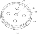
Fig. 1 is a schematic structure diagram of a loudspeaker according to an embodiment of the present invention. -
Fig. 2 is a schematic diagram of the loudspeaker inFig. 1 after partially assembled. -
Fig. 3 is a schematic diagram of the loudspeaker inFig. 1 after assembled. -
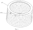
Fig. 4 is a schematic diagram of the dust ring inFig. 1 . - Wherein,
1 - frame; 11 - central hole; 12 - secondary magnetic circuit mounting hole; 13 - flange; 2 - cone; 21 - cone bottom; 211 - main voice coil mounting hole; 212 - secondary voice coil mounting hole; 22 - yoke ring; 3 - main input-driving mechanism; 31 - dust cover; 32 - main voice coil; 320 - lead; 33 - front panel; 34 - first magnetic steel; 35 - T-yoke; 36 - damper; 4 - secondary input-driving mechanism; 41 - dust cover; 42 - secondary voice coil; 420 - lead; 43 - secondary neodymium magnetic steel; 44 - magnetic pole core; 45 - main neodymium magnetic steel; 46 - U-yoke; 47 - dust ring; 470 - lead hole; 5 - audio signal input terminal. - In the following, the preferable embodiments of the present invention are explained in detail combining with the accompanying drawings so that the advantages and features of the present invention can be easily understood by the skilled persons in the art. It should be noted that the explanation on these implementations is to help understanding of the present invention, and is not intended to limit the present invention.
- This embodiment provides a multi-input-driving loudspeaker, herein, "multi-input" refers to multiple audio signal inputs, multiple audio signals are input to multiple voice coils, and the multiple voice coils jointly drive the loudspeaker to produce sound.
- Referring to
Fig. 1 to Fig. 4 , the loudspeaker comprises aframe 1, a cone 2 arranged on theframe 1, and the loudspeaker further comprises a main input driving mechanism 3 and a plurality of secondary input driving mechanisms 4. Wherein, the main input-driving mechanism 3 is arranged between the plurality of secondary input-driving mechanisms 4. Specifically, the plurality of secondary input-driving mechanisms 4 surround the main input-driving mechanism 3 or are located on both sides of the main input-driving mechanism 3, and the number of the secondary input-driving mechanisms 4 is preferably three or more. In this embodiment, there are four secondary input driving mechanisms 4, and the four secondary input-driving mechanisms 4 are arranged at equal intervals around the main input-driving mechanism 3 along a circle. Specifically, as shown inFig. 1 , the main input-driving mechanism 3 is in the middle of the loudspeaker, and comprises amain voice coil 32, a T-yoke 35, and afront panel 33 and a firstmagnetic steel 34 sleeved on the T-yoke 35. A main voicecoil mounting hole 211 is provided in the middle of the cone 2, and an upper end portion of themain voice coil 32 is connected to the main voicecoil mounting hole 211, that is, themain voice coil 32 is connected to the middle of the cone 2, to drive the cone 2. Thefront panel 33 is fixedly connected to theframe 1, specifically, thefront panel 22 is provided with a plurality of lugs raised upwards, the lugs are inserted into corresponding holes in the bottom of theframe 1 to tightly connect thefront panel 33 and theframe 1 by riveting. The middle portion of the T-yoke 35 has an upwards extending columnar portion, thefront panel 33 and the firstmagnetic steel 34 are arranged from top to bottom and respectively opened with a through hole in the middle, so as to be sleeved on the columnar portion of the T-yoke 35, and there are gaps between the inner walls of thefront panel 33 and the firstmagnetic steel 34 and the outer surface of the columnar portion of the T-yoke 35, thereby forming a main magnetic gap, and the corresponding upper and lower surfaces of thefront panel 33, the firstmagnetic steel 34 and the T-yoke 35 are closely fitted and fixedly connected. Acentral hole 11 is provided in the middle of theframe 1, the lower portion of themain voice coil 32 passes through thecentral hole 11 and is inserted into the main magnetic gap, and can move up and down in the main magnetic gap. The firstmagnetic steel 34 is specifically ferrite magnetic steel. - The main input-driving mechanism 3 further comprises a
damper 36, and the damper is specifically located in a cavity between the cone 2 and theframe 1. A through hole is opened in the middle of thedamper 36, themain voice coil 32 is movably inserted in thedamper 36 which is capable of moving in the up and down direction, and the outer surface of themain voice coil 32 and thedamper 36 are closely fitted to prevent thedamper 36 from shaking, therefore, themain voice coil 32 is restricted to only move in the up and down direction, and displacement in the horizontal direction is not allowed. Further, theframe 1 has aflange 13 surrounding thecentral hole 11, theflange 13 encircles thecentral hole 11 and its shaped is a closed circular ring, and thedamper 36 and theflange 13 cooperate with each other so that thedamper 36 is clamped into theflange 13 and retained by the inner walls of theflange 13. - Each secondary input-driving mechanisms 4 respectively comprises a
secondary voice coil 42 and a secondary magnetic circuit assembly formed with a secondary magnetic gap. The cone 2 is provided with a plurality of secondary voicecoil mounting holes 212 correspondingly, and the main voicecoil mounting hole 211 is located between the plurality of secondary voicecoil mounting holes 212. Specifically, the four secondary voicecoil mounting holes 212 are arranged at equal intervals along the circle around the center line of the main voicecoil mounting hole 211. An upper end portion of eachsecondary voice coil 42 is connected to a corresponding secondary voicecoil mounting hole 212, that is, the upper end portions of the foursecondary voice coils 42 are connected to the cone 2, to drive the cone 2. Four secondary magnetic circuit mounting holes 12 are correspondingly opened in theframe 1, thecentral hole 11 is located between the four secondary magnetic circuit mounting holes 12, and the four secondary magnetic circuit mounting holes 12 are arranged at equal intervals along the circle around the center line of thecentral hole 11. A lower portion of eachsecondary voice coil 42 is inserted into a corresponding secondary magnetic gap through a corresponding secondary magnetic circuit mounting holes 12, and is movable in the secondary magnetic gap in an up-and-down direction. The secondary magnetic circuit assembly comprises a U-yoke 46 with an inner cavity, and a second magnetic steel and amagnetic pole core 44 arranged within the U-yoke 46. The second magnetic steel specifically comprises a secondary neodymiummagnetic steel 43 and a main neodymiummagnetic steel 45, the secondary neodymiummagnetic steel 43, themagnetic pole core 44 and the main neodymiummagnetic steel 45 are closely stacked from top to bottom, and there are gaps between the outer surfaces of the three and the inner surface of the U-yoke 46, which form the secondary magnetic gap. The middle portion of the U-yoke 46 is recessed and the outer peripheral edge thereof extends upwards, and the upper edge of the U-yoke 46 is fixedly connected to the secondary magnetic circuit mounting hole 12 of theframe 1. The secondary magnetic circuit assembly in this embodiment adopts the above secondary neodymiummagnetic steel 43 and the main neodymiummagnetic steel 45, which has the advantages of small size and light weight. The secondary input-driving mechanisms 4 are input driving mechanisms without thedamper 36, so it is small in size and light in weight. - In this embodiment, the cone is driven to vibrate through the combination of one main input-driving mechanism 3 and four secondary input-driving mechanisms 4, which increases the driving energy of the loudspeaker; on the premise of increasing the driving energy of the loudspeaker, it makes the overall structure more compact and avoids excessive volume. Moreover, the
front panel 33 of the main input-drive mechanism 3 is fixedly assembled on theframe 1, and the U-yokes 46 of the secondary input drive mechanisms 4 are fixedly assembled on theframe 1, which improves the accuracy of assembling. - Referring to
Fig. 4 , each secondary input-drive mechanism 4 further comprises anelastic dust ring 47, thedust ring 47 is sleeved on the corresponding voice coil, an upper end of thedust ring 47 is tightly coupled with the cone 2, and the lower end of thedust ring 47 is tightly coupled with theframe 1. The material of thedust ring 47 is cloth, plastic, or rubber. In this embodiment, thedust ring 47 is a corrugated hose. A pair of lead holes 470 for the leads of thesecondary voice coil 42 to pass though are opened on thedust ring 47. Thedust ring 47 makes the secondary magnetic circuit assembly substantially in a sealed environment, and effectively prevents dust and the like from entering the secondary magnetic circuit assembly. - In this embodiment, the cone 2 has a flat cone bottom 21 that is round as a whole, the centers of the above-mentioned circle coincide or are collinear with the center of the cone bottom 21, and the main voice
coil mounting hole 211 and the cone bottom 21 are arranged concentrically. The cone bottom 21 is fixedly connected to theframe 1 through ayoke ring 22. In some other embodiments, the cone 2 further has a tapered edge portion extending upwards from the outer edge of the cone bottom 21, and the tapered edge portion is fixedly connected to theframe 1 by theyoke ring 22; further, the cone 2 is provided with a plurality of reinforcing ribs, which extend from the bottom 21 to the tapered edge portion of the cone, thereby enhancing the strength between the bottom 21 and the tapered edge portion of the flat cone. The cone 2 with the above-mentioned shape is superior to the traditional conical loudspeaker in terms of directional expansion width, and the height is lower than that of the traditional conical cone 2, which is beneficial to reducing the overall height of the loudspeaker. In this embodiment, theframe 1 is made of plastic using processes such as injection molding, which is easy to form and has a certain strength. The cone bottom 21 is made of paper pulp, plastic (such as, PP (polypropylene)), ballistic fiber or aluminum alloy, and the made cone 2 is light in weight, has good damping elasticity and rigidity, high temperature and low temperature resistance, waterproof and mildew proof, and the yoke ring is made of sponge, rubber, or cloth materials. - In this embodiment, the plurality of secondary input-driving mechanisms 4 is arranged along the circle, and the entire voice coil is circular. In some other embodiments, the voice coils and the magnetic circuit drive assembles are arranged linearly or rectangularly, and the main input-driving mechanism 3 is in the middle position, and the plurality of secondary input-driving mechanisms 4 are arranged around the main input-driving mechanism 3, or are arranged on both sides of the main input-driving mechanism 3, the shape of the cone is ellipse or rectangle.
- The main input-driving mechanism 3 comprises a
dust cover 31, and the main voicecoil mounting hole 211 is covered with thedust cover 31. Each secondary input-driving mechanism 4 further comprises adust cover 41, and each secondary voicecoil mounting hole 212 is covered with onedust cover 41. The dust covers 31 and 41 are fixedly connected to the cone 2. - The edge portion of the
frame 1 is provided with five pairs of audiosignal input terminals 5, the five pairs of audiosignal input terminals 5 are arranged at intervals along the circle of theframe 1, and theframe 1 is provided with slots for connecting external cables. The pair of leads of themain voice coil 32 are electrically connected to one pair, and the pair of leads of eachsecondary voice coil 42 are electrically connected to the corresponding pair of audiosignal input terminals 5. Wherein, each pair of audiosignal input terminals 5 comprises a positive terminal and a negative terminal, one of a pair of leads is electrically connected to the positive terminal, and the other lead is electrically connected to the negative terminal, to receive the audio signal (analog signal or digital signal) input from the pair of audiosignal input terminal 5. Thus, onemain voice coil 32 and four secondary voice coils 42 are simultaneously driven through the five pairs of audiosignal input terminals 5. Providing multiple integrated terminals for audio signal input in theframe 1 simplifies the manufacture of multi-input-driving loudspeakers, and is also convenient for the connection of audio signal input. - The loudspeaker provided by this embodiment has an ingenious and rational structure by surrounding a plurality of secondary input-driving mechanisms 4 around the main input-driving mechanism 3, and can reduce the size of the magnetic circuit structure by adopting a combined structure of one main input-driving mechanism 3 with a
damper 36 and a plurality of secondary input-driving mechanisms 4 without thedamper 36; multi-audio signal input driving is achieved through a main input-driving mechanism 3 and a plurality of secondary input drive mechanisms 4; by adopting a cone 2 being flat in the middle, the directivity width will be better than traditional loudspeakers; through one main input-driving mechanism 3 and a plurality of secondary input-driving mechanisms 4 to respectively receive audio signal inputs, the original sound reproduction and distortion are superior to traditional loudspeakers; through the use of the cone 2 with a flat bottom, the height of the cone 2 is lower than the height of the traditional conical cone 2, and the reduction in the height of the cone 2 in turn reduces the height of the product; by adopting a driving structure composed of a main input-driving mechanism 3 and a plurality of secondary input-driving mechanisms 4, the loudspeaker sensitivity is increased. - The embodiments described above are only for illustrating the technical concepts and features of the present invention, are preferred embodiments, and are intended to make those skilled in the art being able to understand the present invention and thereby implement it, and should not be concluded to limit the protective scope of this invention.
Claims (14)
- A multi-input-driving loudspeaker, comprising a frame, and a cone arranged on the frame, is characterized in that, the loudspeaker further comprises a main input-driving mechanism and a plurality of secondary input-driving mechanisms, and the main input-driving mechanism is arranged between the plurality of secondary input-driving mechanisms;wherein the main input-driving mechanism comprises a main voice coil, a T-yoke, and a front panel and a first magnetic steel sleeved on the T-yoke, a main voice coil mounting hole is provided in the middle of the cone, an upper end portion of the main voice coil is connected to the main voice coil mounting hole, a main magnetic gap for the main voice coil to be inserted is formed between the T-yoke and the front panel and the first magnetic steel, and a central hole is provided in the middle of the frame that allows the lower portion of the main voice coil to be inserted into the main magnetic gap;each of the secondary input-driving mechanisms comprises a secondary voice coil and a secondary magnetic circuit assembly formed with a secondary magnetic gap, a plurality of secondary voice coil mounting holes are correspondingly provided on the cone, the main voice coil mounting hole is located between the plurality of secondary voice coil mounting holes, an upper end portion of each secondary voice coil is connected to a corresponding secondary voice coil mounting hole, a plurality of secondary magnetic circuit mounting holes are correspondingly provided on the frame, the central hole is located between the plurality of secondary magnetic circuit mounting holes, and a lower portion of each secondary voice coil is inserted into a corresponding secondary magnetic gap through a corresponding secondary magnetic circuit mounting hole.
- The loudspeaker according to claim 1, is characterized in that, each of the secondary input-driving mechanism further comprises an elastic dust ring, and the dust ring is sleeved on the voice coil.
- The loudspeaker according to claim 2, is characterized in that, an upper end of the dust ring is connected with the cone, and a lower end of the dust ring is connected with the frame.
- The loudspeaker according to claim 2, is characterized in that, the dust ring is a corrugated hose.
- The loudspeaker according to claim 1, is characterized in that, the plurality of secondary input-driving mechanisms surround the main input-driving mechanism or are located on both sides of the main input-driving mechanism.
- The loudspeaker according to claim 1, is characterized in that, the cone has a flat-sheet cone bottom, the main voice coil mounting hole and the secondary voice coil mounting holes are opened on the cone bottom.
- The loudspeaker according to claim 1, is characterized in that, there are three or more secondary input driving mechanisms, and the three or more secondary input-driving mechanisms are arranged at equal intervals around the main input-driving mechanism along a circle, the three or more secondary voice coil mounting holes are arranged at intervals along the circle around a center line of the main voice coil mounting hole, and the three or more secondary magnetic circuit mounting holes are arranged at equal intervals along the circle around a center line of the central hole.
- The loudspeaker according to claim 7, is characterized in that, the cone has a flat-sheet cone bottom that is round as a whole, a center of the circle coincides with a center of the cone bottom, and the main voice coil mounting hole and the cone bottom are arranged concentrically.
- The loudspeaker according to claim 6 or 8, is characterized in that, the cone further comprises a tapered edge portion extending obliquely upwards from an outer edge of the cone bottom, and the tapered edge portion is fixedly connected to the frame through a yoke ring.
- The loudspeaker according to claim 1, is characterized in that, the main input-driving mechanism further comprises a damper, and the main voice coil passes through the damper and capable of moving in an up-and-down direction.
- The loudspeaker according to claim 10, is characterized in that, the frame is provided with a flange surrounding the central hole, and the damper and the flange cooperate with each other so that the damper is clamped into the flange.
- The loudspeaker according to claim 1, is characterized in that, the front panel is fixedly connected to a lower portion of the frame.
- The loudspeaker according to claim 1, is characterized in that, the secondary magnetic circuit assembly comprises a U-yoke having an inner cavity, a second magnetic steel and a magnetic pole core arranged within the U-yoke, a secondary magnetic gap is formed between the second magnetic steel and the magnetic pole core and the inner wall of the U-yoke, the secondary voice coil is inserted in the secondary magnetic gap and capable of moving in an up-and-down direction, and an upper edge of the U-yoke is fixedly connected to the secondary magnetic circuit mounting hole of the frame.
- The loudspeaker according to claim 1, is characterized in that, each of the main input-driving mechanism and the secondary input-driving mechanisms comprises a dust cover, and each of the main voice coil mounting hole and the secondary voice coil mounting holes is covered with one dust cover.
Applications Claiming Priority (2)
| Application Number | Priority Date | Filing Date | Title |
|---|---|---|---|
| CN201910635285.9A CN110225440B (en) | 2019-07-15 | 2019-07-15 | A speaker driven by multiple inputs |
| PCT/CN2019/112660 WO2021007983A1 (en) | 2019-07-15 | 2019-10-23 | Multiple-input driven loudspeaker |
Publications (3)
| Publication Number | Publication Date |
|---|---|
| EP4002879A1 true EP4002879A1 (en) | 2022-05-25 |
| EP4002879A4 EP4002879A4 (en) | 2023-08-02 |
| EP4002879B1 EP4002879B1 (en) | 2025-07-09 |
Family
ID=67813186
Family Applications (1)
| Application Number | Title | Priority Date | Filing Date |
|---|---|---|---|
| EP19937763.1A Active EP4002879B1 (en) | 2019-07-15 | 2019-10-23 | Multiple-input driven loudspeaker |
Country Status (5)
| Country | Link |
|---|---|
| US (1) | US11882423B2 (en) |
| EP (1) | EP4002879B1 (en) |
| JP (2) | JP7259095B2 (en) |
| CN (2) | CN119450318A (en) |
| WO (1) | WO2021007983A1 (en) |
Families Citing this family (7)
| Publication number | Priority date | Publication date | Assignee | Title |
|---|---|---|---|---|
| CN119450318A (en) * | 2019-07-15 | 2025-02-14 | 苏州茹声电子有限公司 | A speaker |
| CN212752626U (en) * | 2020-09-02 | 2021-03-19 | 苏州上声电子股份有限公司 | A small speaker with two cones |
| CN112073880B (en) | 2020-09-02 | 2025-04-08 | 苏州上声电子股份有限公司 | Small-sized loudspeaker with multiple sound basins |
| CN112073881B (en) * | 2020-09-02 | 2025-04-08 | 苏州上声电子股份有限公司 | A multi-cone loudspeaker |
| CN218243832U (en) * | 2022-09-09 | 2023-01-06 | 苏州上声电子股份有限公司 | Loudspeaker cone and loudspeaker |
| CN116709142B (en) * | 2023-07-31 | 2023-10-27 | 江苏裕成电子有限公司 | Multi-voice coil loudspeaker module |
| CN121218076A (en) * | 2025-11-28 | 2025-12-26 | 美特科技(苏州)有限公司 | Vibration system of sound-generating device and sound-generating device |
Family Cites Families (26)
| Publication number | Priority date | Publication date | Assignee | Title |
|---|---|---|---|---|
| US2070977A (en) * | 1935-06-04 | 1937-02-16 | Magnavox Co | Sound reproducer |
| US3509290A (en) * | 1966-05-03 | 1970-04-28 | Nippon Musical Instruments Mfg | Flat-plate type loudspeaker with frame mounted drivers |
| JPS5379525A (en) * | 1976-12-23 | 1978-07-14 | Sony Corp | Compound diaphtagm for speakers |
| JPS5525284A (en) * | 1978-08-14 | 1980-02-22 | Sony Corp | Mfb speaker system |
| JPS5525286A (en) * | 1978-08-14 | 1980-02-22 | Sony Corp | Speaker |
| JPS5811799B2 (en) * | 1981-12-10 | 1983-03-04 | ソニー株式会社 | speaker |
| FR2571581B1 (en) | 1984-07-18 | 1987-01-16 | Horlogerie Photograph Fse | TELEPHONE RECEIVER CAPSULE COMPATIBLE WITH HEARING AID |
| JP3148520B2 (en) * | 1994-06-06 | 2001-03-19 | 株式会社ケンウッド | Speaker structure |
| JP3260062B2 (en) * | 1995-09-04 | 2002-02-25 | 株式会社ケンウッド | Speaker |
| JP3893694B2 (en) * | 1996-10-30 | 2007-03-14 | 松下電器産業株式会社 | Speaker |
| GB9709438D0 (en) | 1997-05-10 | 1997-07-02 | New Transducers Ltd | Loudspeaker transducer |
| JP3416023B2 (en) * | 1997-05-22 | 2003-06-16 | 株式会社ケンウッド | Speaker |
| JP3296751B2 (en) * | 1997-05-22 | 2002-07-02 | 株式会社ケンウッド | Speaker manufacturing method and speaker |
| FR2818487B1 (en) * | 2000-12-14 | 2006-08-18 | Albert Jakoubovitch | MULTI-ENGINE SPEAKERS |
| US8144916B2 (en) | 2006-09-27 | 2012-03-27 | Bailiang Zhang | Vibrating system of panel form electrodynamic loudspeaker |
| US8009857B2 (en) * | 2007-02-15 | 2011-08-30 | Wisdom Audio Corp. | Induction motor for loudspeaker |
| US7856115B2 (en) * | 2007-11-30 | 2010-12-21 | Clair Brothers Audio Systems Inc. | Optimized moving-coil loudspeaker |
| CN201263213Y (en) * | 2008-08-22 | 2009-06-24 | 无锡杰夫电声有限公司 | Thin type loudspeaker with double magnetic circuit structure |
| CN101902676B (en) * | 2010-08-31 | 2012-12-19 | 无锡杰夫电声有限公司 | Dual-sound basin thin speaker |
| CN102291651B (en) * | 2011-06-16 | 2014-01-22 | 无锡杰夫电声有限公司 | Dual-cone thin loudspeaker with step structure |
| CN204733375U (en) | 2015-06-29 | 2015-10-28 | 歌尔声学股份有限公司 | Loud speaker |
| CN107454530B (en) * | 2017-09-22 | 2023-11-03 | 国光电器股份有限公司 | Loudspeaker device |
| CN207427463U (en) * | 2017-11-23 | 2018-05-29 | 嘉兴旗声电子有限公司 | A kind of five magnetic high-performance micro loud speakers |
| CN208798193U (en) * | 2018-08-16 | 2019-04-26 | 广州市拓进数码科技有限公司 | coaxial horn |
| CN119450318A (en) | 2019-07-15 | 2025-02-14 | 苏州茹声电子有限公司 | A speaker |
| CN210053561U (en) * | 2019-07-15 | 2020-02-11 | 苏州茹声电子有限公司 | Loudspeaker driven by multipath input |
-
2019
- 2019-07-15 CN CN202411390552.8A patent/CN119450318A/en active Pending
- 2019-07-15 CN CN201910635285.9A patent/CN110225440B/en active Active
- 2019-10-23 WO PCT/CN2019/112660 patent/WO2021007983A1/en not_active Ceased
- 2019-10-23 JP JP2021577942A patent/JP7259095B2/en active Active
- 2019-10-23 EP EP19937763.1A patent/EP4002879B1/en active Active
- 2019-10-23 US US17/623,320 patent/US11882423B2/en active Active
-
2023
- 2023-04-05 JP JP2023061770A patent/JP7579906B2/en active Active
Also Published As
| Publication number | Publication date |
|---|---|
| JP7259095B2 (en) | 2023-04-17 |
| CN110225440B (en) | 2024-10-15 |
| US11882423B2 (en) | 2024-01-23 |
| CN119450318A (en) | 2025-02-14 |
| US20220369039A1 (en) | 2022-11-17 |
| EP4002879B1 (en) | 2025-07-09 |
| JP7579906B2 (en) | 2024-11-08 |
| WO2021007983A1 (en) | 2021-01-21 |
| CN110225440A (en) | 2019-09-10 |
| JP2023085473A (en) | 2023-06-20 |
| JP2022539203A (en) | 2022-09-07 |
| EP4002879A4 (en) | 2023-08-02 |
Similar Documents
| Publication | Publication Date | Title |
|---|---|---|
| EP4002879B1 (en) | Multiple-input driven loudspeaker | |
| EP3996388B1 (en) | Multi-input driven loudspeaker | |
| US12302081B2 (en) | Multi-input-driving loudspeaker | |
| EP4002880A1 (en) | Multi-path input-driving small loudspeaker and mid-treble loudspeaker | |
| US20240298106A1 (en) | Dual-cone small speaker | |
| WO2022048691A1 (en) | Dual-cone speaker | |
| CN110278516A (en) | The loudspeaker of multichannel input driving | |
| CN110381422A (en) | A kind of loudspeaker of multichannel input driving | |
| CN210053561U (en) | Loudspeaker driven by multipath input | |
| KR102045267B1 (en) | Copper plate damper for slim type speaker | |
| CN210053568U (en) | Multi-channel input driven small-sized loudspeaker and medium-high-sound loudspeaker | |
| US20240089665A1 (en) | Multi-cone small speaker | |
| KR20230000640A (en) | Coil separating and mounting structure in coaxial exciter | |
| JPH06165280A (en) | Speaker device and television receiver using the same |
Legal Events
| Date | Code | Title | Description |
|---|---|---|---|
| STAA | Information on the status of an ep patent application or granted ep patent |
Free format text: STATUS: THE INTERNATIONAL PUBLICATION HAS BEEN MADE |
|
| PUAI | Public reference made under article 153(3) epc to a published international application that has entered the european phase |
Free format text: ORIGINAL CODE: 0009012 |
|
| STAA | Information on the status of an ep patent application or granted ep patent |
Free format text: STATUS: REQUEST FOR EXAMINATION WAS MADE |
|
| 17P | Request for examination filed |
Effective date: 20211221 |
|
| AK | Designated contracting states |
Kind code of ref document: A1 Designated state(s): AL AT BE BG CH CY CZ DE DK EE ES FI FR GB GR HR HU IE IS IT LI LT LU LV MC MK MT NL NO PL PT RO RS SE SI SK SM TR |
|
| DAV | Request for validation of the european patent (deleted) | ||
| DAX | Request for extension of the european patent (deleted) | ||
| A4 | Supplementary search report drawn up and despatched |
Effective date: 20230630 |
|
| RIC1 | Information provided on ipc code assigned before grant |
Ipc: H04R 9/04 20060101ALI20230626BHEP Ipc: H04R 7/04 20060101ALI20230626BHEP Ipc: H04R 9/06 20060101ALI20230626BHEP Ipc: H04R 9/02 20060101AFI20230626BHEP |
|
| GRAP | Despatch of communication of intention to grant a patent |
Free format text: ORIGINAL CODE: EPIDOSNIGR1 |
|
| STAA | Information on the status of an ep patent application or granted ep patent |
Free format text: STATUS: GRANT OF PATENT IS INTENDED |
|
| INTG | Intention to grant announced |
Effective date: 20250311 |
|
| GRAS | Grant fee paid |
Free format text: ORIGINAL CODE: EPIDOSNIGR3 |
|
| GRAA | (expected) grant |
Free format text: ORIGINAL CODE: 0009210 |
|
| STAA | Information on the status of an ep patent application or granted ep patent |
Free format text: STATUS: THE PATENT HAS BEEN GRANTED |
|
| AK | Designated contracting states |
Kind code of ref document: B1 Designated state(s): AL AT BE BG CH CY CZ DE DK EE ES FI FR GB GR HR HU IE IS IT LI LT LU LV MC MK MT NL NO PL PT RO RS SE SI SK SM TR |
|
| REG | Reference to a national code |
Ref country code: GB Ref legal event code: FG4D |
|
| REG | Reference to a national code |
Ref country code: CH Ref legal event code: EP |
|
| REG | Reference to a national code |
Ref country code: IE Ref legal event code: FG4D |
|
| REG | Reference to a national code |
Ref country code: DE Ref legal event code: R096 Ref document number: 602019072488 Country of ref document: DE |
|
| P01 | Opt-out of the competence of the unified patent court (upc) registered |
Free format text: CASE NUMBER: UPC_APP_0351_4002879/2025 Effective date: 20250715 |
|
| REG | Reference to a national code |
Ref country code: NL Ref legal event code: MP Effective date: 20250709 |
|
| PG25 | Lapsed in a contracting state [announced via postgrant information from national office to epo] |
Ref country code: PT Free format text: LAPSE BECAUSE OF FAILURE TO SUBMIT A TRANSLATION OF THE DESCRIPTION OR TO PAY THE FEE WITHIN THE PRESCRIBED TIME-LIMIT Effective date: 20251110 |
|
| PG25 | Lapsed in a contracting state [announced via postgrant information from national office to epo] |
Ref country code: NL Free format text: LAPSE BECAUSE OF FAILURE TO SUBMIT A TRANSLATION OF THE DESCRIPTION OR TO PAY THE FEE WITHIN THE PRESCRIBED TIME-LIMIT Effective date: 20250709 |
|
| REG | Reference to a national code |
Ref country code: AT Ref legal event code: MK05 Ref document number: 1812998 Country of ref document: AT Kind code of ref document: T Effective date: 20250709 |
|
| PG25 | Lapsed in a contracting state [announced via postgrant information from national office to epo] |
Ref country code: IS Free format text: LAPSE BECAUSE OF FAILURE TO SUBMIT A TRANSLATION OF THE DESCRIPTION OR TO PAY THE FEE WITHIN THE PRESCRIBED TIME-LIMIT Effective date: 20251109 |
|
| PGFP | Annual fee paid to national office [announced via postgrant information from national office to epo] |
Ref country code: DE Payment date: 20251031 Year of fee payment: 7 |
|
| PG25 | Lapsed in a contracting state [announced via postgrant information from national office to epo] |
Ref country code: NO Free format text: LAPSE BECAUSE OF FAILURE TO SUBMIT A TRANSLATION OF THE DESCRIPTION OR TO PAY THE FEE WITHIN THE PRESCRIBED TIME-LIMIT Effective date: 20251009 |
|
| REG | Reference to a national code |
Ref country code: LT Ref legal event code: MG9D |
|
| PG25 | Lapsed in a contracting state [announced via postgrant information from national office to epo] |
Ref country code: AT Free format text: LAPSE BECAUSE OF FAILURE TO SUBMIT A TRANSLATION OF THE DESCRIPTION OR TO PAY THE FEE WITHIN THE PRESCRIBED TIME-LIMIT Effective date: 20250709 |
|
| PG25 | Lapsed in a contracting state [announced via postgrant information from national office to epo] |
Ref country code: FI Free format text: LAPSE BECAUSE OF FAILURE TO SUBMIT A TRANSLATION OF THE DESCRIPTION OR TO PAY THE FEE WITHIN THE PRESCRIBED TIME-LIMIT Effective date: 20250709 |
|
| PGFP | Annual fee paid to national office [announced via postgrant information from national office to epo] |
Ref country code: IT Payment date: 20251029 Year of fee payment: 7 |
|
| PG25 | Lapsed in a contracting state [announced via postgrant information from national office to epo] |
Ref country code: HR Free format text: LAPSE BECAUSE OF FAILURE TO SUBMIT A TRANSLATION OF THE DESCRIPTION OR TO PAY THE FEE WITHIN THE PRESCRIBED TIME-LIMIT Effective date: 20250709 |
|
| PGFP | Annual fee paid to national office [announced via postgrant information from national office to epo] |
Ref country code: FR Payment date: 20251028 Year of fee payment: 7 |
|
| PG25 | Lapsed in a contracting state [announced via postgrant information from national office to epo] |
Ref country code: GR Free format text: LAPSE BECAUSE OF FAILURE TO SUBMIT A TRANSLATION OF THE DESCRIPTION OR TO PAY THE FEE WITHIN THE PRESCRIBED TIME-LIMIT Effective date: 20251010 |
|
| PG25 | Lapsed in a contracting state [announced via postgrant information from national office to epo] |
Ref country code: SE Free format text: LAPSE BECAUSE OF FAILURE TO SUBMIT A TRANSLATION OF THE DESCRIPTION OR TO PAY THE FEE WITHIN THE PRESCRIBED TIME-LIMIT Effective date: 20250709 |
|
| PG25 | Lapsed in a contracting state [announced via postgrant information from national office to epo] |
Ref country code: LV Free format text: LAPSE BECAUSE OF FAILURE TO SUBMIT A TRANSLATION OF THE DESCRIPTION OR TO PAY THE FEE WITHIN THE PRESCRIBED TIME-LIMIT Effective date: 20250709 |
|
| PG25 | Lapsed in a contracting state [announced via postgrant information from national office to epo] |
Ref country code: PL Free format text: LAPSE BECAUSE OF FAILURE TO SUBMIT A TRANSLATION OF THE DESCRIPTION OR TO PAY THE FEE WITHIN THE PRESCRIBED TIME-LIMIT Effective date: 20250709 Ref country code: BG Free format text: LAPSE BECAUSE OF FAILURE TO SUBMIT A TRANSLATION OF THE DESCRIPTION OR TO PAY THE FEE WITHIN THE PRESCRIBED TIME-LIMIT Effective date: 20250709 |
|
| PG25 | Lapsed in a contracting state [announced via postgrant information from national office to epo] |
Ref country code: RS Free format text: LAPSE BECAUSE OF FAILURE TO SUBMIT A TRANSLATION OF THE DESCRIPTION OR TO PAY THE FEE WITHIN THE PRESCRIBED TIME-LIMIT Effective date: 20251009 |
|
| PG25 | Lapsed in a contracting state [announced via postgrant information from national office to epo] |
Ref country code: ES Free format text: LAPSE BECAUSE OF FAILURE TO SUBMIT A TRANSLATION OF THE DESCRIPTION OR TO PAY THE FEE WITHIN THE PRESCRIBED TIME-LIMIT Effective date: 20250709 |
|
| PG25 | Lapsed in a contracting state [announced via postgrant information from national office to epo] |
Ref country code: RO Free format text: LAPSE BECAUSE OF FAILURE TO SUBMIT A TRANSLATION OF THE DESCRIPTION OR TO PAY THE FEE WITHIN THE PRESCRIBED TIME-LIMIT Effective date: 20250709 |
|
| PG25 | Lapsed in a contracting state [announced via postgrant information from national office to epo] |
Ref country code: SM Free format text: LAPSE BECAUSE OF FAILURE TO SUBMIT A TRANSLATION OF THE DESCRIPTION OR TO PAY THE FEE WITHIN THE PRESCRIBED TIME-LIMIT Effective date: 20250709 |
|
| REG | Reference to a national code |
Ref country code: DE Ref legal event code: R097 Ref document number: 602019072488 Country of ref document: DE |
|
| PG25 | Lapsed in a contracting state [announced via postgrant information from national office to epo] |
Ref country code: DK Free format text: LAPSE BECAUSE OF FAILURE TO SUBMIT A TRANSLATION OF THE DESCRIPTION OR TO PAY THE FEE WITHIN THE PRESCRIBED TIME-LIMIT Effective date: 20250709 |
|
| PG25 | Lapsed in a contracting state [announced via postgrant information from national office to epo] |
Ref country code: CZ Free format text: LAPSE BECAUSE OF FAILURE TO SUBMIT A TRANSLATION OF THE DESCRIPTION OR TO PAY THE FEE WITHIN THE PRESCRIBED TIME-LIMIT Effective date: 20250709 |
|
| PG25 | Lapsed in a contracting state [announced via postgrant information from national office to epo] |
Ref country code: SK Free format text: LAPSE BECAUSE OF FAILURE TO SUBMIT A TRANSLATION OF THE DESCRIPTION OR TO PAY THE FEE WITHIN THE PRESCRIBED TIME-LIMIT Effective date: 20250709 Ref country code: EE Free format text: LAPSE BECAUSE OF FAILURE TO SUBMIT A TRANSLATION OF THE DESCRIPTION OR TO PAY THE FEE WITHIN THE PRESCRIBED TIME-LIMIT Effective date: 20250709 |
|
| PLBE | No opposition filed within time limit |
Free format text: ORIGINAL CODE: 0009261 |
|
| STAA | Information on the status of an ep patent application or granted ep patent |
Free format text: STATUS: NO OPPOSITION FILED WITHIN TIME LIMIT |
|
| REG | Reference to a national code |
Ref country code: CH Ref legal event code: L10 Free format text: ST27 STATUS EVENT CODE: U-0-0-L10-L00 (AS PROVIDED BY THE NATIONAL OFFICE) Effective date: 20260521 |
|
| REG | Reference to a national code |
Ref country code: CH Ref legal event code: H13 Free format text: ST27 STATUS EVENT CODE: U-0-0-H10-H13 (AS PROVIDED BY THE NATIONAL OFFICE) Effective date: 20260527 |
|
| PG25 | Lapsed in a contracting state [announced via postgrant information from national office to epo] |
Ref country code: LU Free format text: LAPSE BECAUSE OF NON-PAYMENT OF DUE FEES Effective date: 20251023 |
|
| 26N | No opposition filed |
Effective date: 20260410 |
|
| REG | Reference to a national code |
Ref country code: BE Ref legal event code: MM Effective date: 20251031 |
|
| GBPC | Gb: european patent ceased through non-payment of renewal fee |
Effective date: 20251023 |
|
| PG25 | Lapsed in a contracting state [announced via postgrant information from national office to epo] |
Ref country code: LT Free format text: LAPSE BECAUSE OF FAILURE TO SUBMIT A TRANSLATION OF THE DESCRIPTION OR TO PAY THE FEE WITHIN THE PRESCRIBED TIME-LIMIT Effective date: 20250709 Ref country code: MC Free format text: LAPSE BECAUSE OF FAILURE TO SUBMIT A TRANSLATION OF THE DESCRIPTION OR TO PAY THE FEE WITHIN THE PRESCRIBED TIME-LIMIT Effective date: 20250709 |
|
| PG25 | Lapsed in a contracting state [announced via postgrant information from national office to epo] |
Ref country code: GB Free format text: LAPSE BECAUSE OF NON-PAYMENT OF DUE FEES Effective date: 20251023 |
|
| PG25 | Lapsed in a contracting state [announced via postgrant information from national office to epo] |
Ref country code: CH Free format text: LAPSE BECAUSE OF NON-PAYMENT OF DUE FEES Effective date: 20251031 Ref country code: BE Free format text: LAPSE BECAUSE OF NON-PAYMENT OF DUE FEES Effective date: 20251031 |