EP4002876B1 - Ohrhörer mit integrierter vorrichtung und drahtlosfunktion - Google Patents
Ohrhörer mit integrierter vorrichtung und drahtlosfunktion Download PDFInfo
- Publication number
- EP4002876B1 EP4002876B1 EP21217072.4A EP21217072A EP4002876B1 EP 4002876 B1 EP4002876 B1 EP 4002876B1 EP 21217072 A EP21217072 A EP 21217072A EP 4002876 B1 EP4002876 B1 EP 4002876B1
- Authority
- EP
- European Patent Office
- Prior art keywords
- board
- integrated device
- hearable
- implementations
- flex
- Prior art date
- Legal status (The legal status is an assumption and is not a legal conclusion. Google has not performed a legal analysis and makes no representation as to the accuracy of the status listed.)
- Active
Links
Images


Classifications
-
- H—ELECTRICITY
- H04—ELECTRIC COMMUNICATION TECHNIQUE
- H04R—LOUDSPEAKERS, MICROPHONES, GRAMOPHONE PICK-UPS OR LIKE ACOUSTIC ELECTROMECHANICAL TRANSDUCERS; DEAF-AID SETS; PUBLIC ADDRESS SYSTEMS
- H04R25/00—Deaf-aid sets, i.e. electro-acoustic or electro-mechanical hearing aids; Electric tinnitus maskers providing an auditory perception
- H04R25/55—Deaf-aid sets, i.e. electro-acoustic or electro-mechanical hearing aids; Electric tinnitus maskers providing an auditory perception using an external connection, either wireless or wired
- H04R25/554—Deaf-aid sets, i.e. electro-acoustic or electro-mechanical hearing aids; Electric tinnitus maskers providing an auditory perception using an external connection, either wireless or wired using a wireless connection, e.g. between microphone and amplifier or using Tcoils
-
- H—ELECTRICITY
- H04—ELECTRIC COMMUNICATION TECHNIQUE
- H04R—LOUDSPEAKERS, MICROPHONES, GRAMOPHONE PICK-UPS OR LIKE ACOUSTIC ELECTROMECHANICAL TRANSDUCERS; DEAF-AID SETS; PUBLIC ADDRESS SYSTEMS
- H04R1/00—Details of transducers, loudspeakers or microphones
- H04R1/02—Casings; Cabinets ; Supports therefor; Mountings therein
- H04R1/028—Casings; Cabinets ; Supports therefor; Mountings therein associated with devices performing functions other than acoustics, e.g. electric candles
-
- H—ELECTRICITY
- H04—ELECTRIC COMMUNICATION TECHNIQUE
- H04R—LOUDSPEAKERS, MICROPHONES, GRAMOPHONE PICK-UPS OR LIKE ACOUSTIC ELECTROMECHANICAL TRANSDUCERS; DEAF-AID SETS; PUBLIC ADDRESS SYSTEMS
- H04R1/00—Details of transducers, loudspeakers or microphones
- H04R1/10—Earpieces; Attachments therefor ; Earphones; Monophonic headphones
- H04R1/1016—Earpieces of the intra-aural type
-
- H—ELECTRICITY
- H04—ELECTRIC COMMUNICATION TECHNIQUE
- H04R—LOUDSPEAKERS, MICROPHONES, GRAMOPHONE PICK-UPS OR LIKE ACOUSTIC ELECTROMECHANICAL TRANSDUCERS; DEAF-AID SETS; PUBLIC ADDRESS SYSTEMS
- H04R1/00—Details of transducers, loudspeakers or microphones
- H04R1/10—Earpieces; Attachments therefor ; Earphones; Monophonic headphones
- H04R1/1025—Accumulators or arrangements for charging
-
- H—ELECTRICITY
- H04—ELECTRIC COMMUNICATION TECHNIQUE
- H04R—LOUDSPEAKERS, MICROPHONES, GRAMOPHONE PICK-UPS OR LIKE ACOUSTIC ELECTROMECHANICAL TRANSDUCERS; DEAF-AID SETS; PUBLIC ADDRESS SYSTEMS
- H04R1/00—Details of transducers, loudspeakers or microphones
- H04R1/10—Earpieces; Attachments therefor ; Earphones; Monophonic headphones
- H04R1/1091—Details not provided for in groups H04R1/1008 - H04R1/1083
-
- H—ELECTRICITY
- H04—ELECTRIC COMMUNICATION TECHNIQUE
- H04R—LOUDSPEAKERS, MICROPHONES, GRAMOPHONE PICK-UPS OR LIKE ACOUSTIC ELECTROMECHANICAL TRANSDUCERS; DEAF-AID SETS; PUBLIC ADDRESS SYSTEMS
- H04R25/00—Deaf-aid sets, i.e. electro-acoustic or electro-mechanical hearing aids; Electric tinnitus maskers providing an auditory perception
- H04R25/60—Mounting or interconnection of hearing aid parts, e.g. inside tips, housings or to ossicles
- H04R25/609—Mounting or interconnection of hearing aid parts, e.g. inside tips, housings or to ossicles of circuitry
-
- H—ELECTRICITY
- H05—ELECTRIC TECHNIQUES NOT OTHERWISE PROVIDED FOR
- H05K—PRINTED CIRCUITS; CASINGS OR CONSTRUCTIONAL DETAILS OF ELECTRIC APPARATUS; MANUFACTURE OF ASSEMBLAGES OF ELECTRICAL COMPONENTS
- H05K1/00—Printed circuits
- H05K1/02—Details
- H05K1/14—Structural association of two or more printed circuits
- H05K1/147—Structural association of two or more printed circuits at least one of the printed circuits being bent or folded, e.g. by using a flexible printed circuit
-
- H—ELECTRICITY
- H05—ELECTRIC TECHNIQUES NOT OTHERWISE PROVIDED FOR
- H05K—PRINTED CIRCUITS; CASINGS OR CONSTRUCTIONAL DETAILS OF ELECTRIC APPARATUS; MANUFACTURE OF ASSEMBLAGES OF ELECTRICAL COMPONENTS
- H05K7/00—Constructional details common to different types of electric apparatus
- H05K7/14—Mounting supporting structure in casing or on frame or rack
- H05K7/1417—Mounting supporting structure in casing or on frame or rack having securing means for mounting boards, plates or wiring boards
-
- H—ELECTRICITY
- H04—ELECTRIC COMMUNICATION TECHNIQUE
- H04R—LOUDSPEAKERS, MICROPHONES, GRAMOPHONE PICK-UPS OR LIKE ACOUSTIC ELECTROMECHANICAL TRANSDUCERS; DEAF-AID SETS; PUBLIC ADDRESS SYSTEMS
- H04R2225/00—Details of deaf aids covered by H04R25/00, not provided for in any of its subgroups
- H04R2225/023—Completely in the canal [CIC] hearing aids
-
- H—ELECTRICITY
- H04—ELECTRIC COMMUNICATION TECHNIQUE
- H04R—LOUDSPEAKERS, MICROPHONES, GRAMOPHONE PICK-UPS OR LIKE ACOUSTIC ELECTROMECHANICAL TRANSDUCERS; DEAF-AID SETS; PUBLIC ADDRESS SYSTEMS
- H04R2225/00—Details of deaf aids covered by H04R25/00, not provided for in any of its subgroups
- H04R2225/025—In the ear hearing aids [ITE] hearing aids
-
- H—ELECTRICITY
- H04—ELECTRIC COMMUNICATION TECHNIQUE
- H04R—LOUDSPEAKERS, MICROPHONES, GRAMOPHONE PICK-UPS OR LIKE ACOUSTIC ELECTROMECHANICAL TRANSDUCERS; DEAF-AID SETS; PUBLIC ADDRESS SYSTEMS
- H04R2225/00—Details of deaf aids covered by H04R25/00, not provided for in any of its subgroups
- H04R2225/31—Aspects of the use of accumulators in hearing aids, e.g. rechargeable batteries or fuel cells
-
- H—ELECTRICITY
- H04—ELECTRIC COMMUNICATION TECHNIQUE
- H04R—LOUDSPEAKERS, MICROPHONES, GRAMOPHONE PICK-UPS OR LIKE ACOUSTIC ELECTROMECHANICAL TRANSDUCERS; DEAF-AID SETS; PUBLIC ADDRESS SYSTEMS
- H04R2420/00—Details of connection covered by H04R, not provided for in its groups
- H04R2420/07—Applications of wireless loudspeakers or wireless microphones
-
- H—ELECTRICITY
- H04—ELECTRIC COMMUNICATION TECHNIQUE
- H04R—LOUDSPEAKERS, MICROPHONES, GRAMOPHONE PICK-UPS OR LIKE ACOUSTIC ELECTROMECHANICAL TRANSDUCERS; DEAF-AID SETS; PUBLIC ADDRESS SYSTEMS
- H04R25/00—Deaf-aid sets, i.e. electro-acoustic or electro-mechanical hearing aids; Electric tinnitus maskers providing an auditory perception
- H04R25/35—Deaf-aid sets, i.e. electro-acoustic or electro-mechanical hearing aids; Electric tinnitus maskers providing an auditory perception using translation techniques
-
- H—ELECTRICITY
- H05—ELECTRIC TECHNIQUES NOT OTHERWISE PROVIDED FOR
- H05K—PRINTED CIRCUITS; CASINGS OR CONSTRUCTIONAL DETAILS OF ELECTRIC APPARATUS; MANUFACTURE OF ASSEMBLAGES OF ELECTRICAL COMPONENTS
- H05K1/00—Printed circuits
- H05K1/02—Details
- H05K1/0277—Bendability or stretchability details
- H05K1/028—Bending or folding regions of flexible printed circuits
-
- H—ELECTRICITY
- H05—ELECTRIC TECHNIQUES NOT OTHERWISE PROVIDED FOR
- H05K—PRINTED CIRCUITS; CASINGS OR CONSTRUCTIONAL DETAILS OF ELECTRIC APPARATUS; MANUFACTURE OF ASSEMBLAGES OF ELECTRICAL COMPONENTS
- H05K1/00—Printed circuits
- H05K1/18—Printed circuits structurally associated with non-printed electric components
-
- H—ELECTRICITY
- H05—ELECTRIC TECHNIQUES NOT OTHERWISE PROVIDED FOR
- H05K—PRINTED CIRCUITS; CASINGS OR CONSTRUCTIONAL DETAILS OF ELECTRIC APPARATUS; MANUFACTURE OF ASSEMBLAGES OF ELECTRICAL COMPONENTS
- H05K2201/00—Indexing scheme relating to printed circuits covered by H05K1/00
- H05K2201/10—Details of components or other objects attached to or integrated in a printed circuit board
- H05K2201/10007—Types of components
- H05K2201/10083—Electromechanical or electro-acoustic component, e.g. microphone
Definitions
- Various features relate generally to a hearable device, and more specifically to a hearable device that includes an integrated device and wireless functionality.
- FIG. 1 illustrates a hearing aid 100 that includes a shell 102, a tube 104 and an ear piece 106.
- the shell 102 includes a battery 120, a microphone 122 and a speaker 124.
- the shell 102 encapsulates the battery 120, the microphone 122 and the speaker 124.
- the shell 102 is coupled to the tube 104.
- the tube 104 is coupled to the ear piece 106.
- An ear e.g., human ear
- the outer ear includes an ear canal, an auricle and a lobe.
- the ear piece 106 is designed to fit into the ear canal of an ear.
- the shell 102 and the tube 104 are positioned outside of the ear.
- the shell 102 may be positioned behind the auricle of the outer ear.
- the hearing aid 100 operates by using the microphone 122 to pick out sounds.
- the speaker 124 then emits the sounds through the tube 104 and to the ear piece 106.
- the sound coming out of the ear piece 106 then travels through the ear canal, to the middle ear and the inner ear.
- the battery 120 provides the power to operate the microphone 122 and the speaker 124. Once the battery 120 runs low or is out of power, the battery 120 is replaced with another battery.
- the hearing aid 100 has limited functionality.
- the design of the hearing aid 100 is such that it is fits awkwardly outside of the ear. Therefore, there is an ongoing need for better hearable devices with better form factors, and more functionalities and capabilities.
- a circuit module comprising: a base element integrated circuit having at least two major surfaces and comprising a first and a second set of contacts; a support element integrated circuit having at least two major surfaces and comprising a first and a second set of contacts, the base element integrated circuit and the support element integrated circuit being in a stacked disposition relative to each other; a flex circuit comprising a first conductive layer disposed at a first conductive layer level of the flex circuit and a second conductive layer disposed at a second conductive layer of the flex circuit, between which levels is an intermediate layer, the first conductive layer level having base element flex contacts and the second conductive layer level having support element flex contacts, the base element flex contacts at the first conductive layer level being in contact with the first and second sets of contacts of the base element integrated circuit and the support element flex contacts at the second conductive layer level being in contact with the first and second sets of contacts of the support element integrated circuit.
- US2010/0158294A1 describes hearing assistance device for a user, device comprising: a housing; a battery disposed in the housing; a substrate disposed in the housing, the substrate adapted to conform around the battery; and hearing assistance electronics mounted to the substrate.
- US2010/0158296A1 describes a hearing assistance device for an ear of a wearer comprising a microphone for receiving sound, hearing assistance electronics in communications with the microphone, the hearing assistance electronics including a hybrid circuit, and a wearable housing adapted to house at least the hearing assistance electronics.
- the hybrid circuit comprises a first integrated circuit die having one or more through-silicon-vias (TSVs), a first redistribution layer disposed on a surface of the first integrated circuit, and a second integrated circuit die having one or more contacts, the second integrated circuit die disposed on the first redistribution layer, wherein the first redistribution layer is adapted to connect one or more of the one or more TSVs of the first integrated circuit die to one or more of the one or more contacts of the second integrated circuit die.
- TSVs through-silicon-vias
- US2016/0050474A1 describes a circuit assembly, comprising: a printed circuit board assembly, comprising: a first circuit board; a second circuit board; a first flexible substrate interposed between, and continuous with, the first circuit board and the second circuit board; and a second flexible substrate extending from, and continuous with, the second circuit board; one or more electronic circuits disposed along one or more of the first circuit board or the second circuit board; and a battery to power the one or more electronic circuits, the battery comprising a first major face, a second major face, and one or more side faces; the printed circuit board assembly folded about the battery with the first circuit board adjacent to the first major face, the second circuit board adjacent to the second major face, and the first flexible substrate spanning the one or more side faces.
- Various features relate generally to a hearable device, and more specifically to a hearable device that includes an integrated device and wireless functionality.
- a hearable device that includes a board, a first integrated device coupled to the board, a speaker coupled to the first integrated device, a microphone coupled to the first integrated device and a power source configured to provide power to the first integrated device, the speaker and the microphone.
- the hearable device has a length of about 2.4 centimeter (cm) or less, and a diameter of about 1.2 centimeter (cm) or less.
- the first integrated device includes a processor.
- the first integrated device may include a low power processor configured to operate with 5-2000 micro-Watts of processor power consumption.
- the hearable device further includes a flex board coupled to the board (e.g., printed circuit board (PCB)).
- the hearable device further includes another integrated device configured to provide wireless communication capabilities.
- the hearable device further includes a coil and a wireless charging circuit to enable wireless charging of the power source.
- the hearable device includes another integrated device configured to provide compression/decompression (CODEC) functionality.
- CDEC compression/decompression
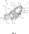
- FIG. 2 illustrates an example of a hearable device 200 that includes several functionalities and capabilities.
- the hearable device 200 includes a first board 202, a second board 204, a third board 206, a flex board 208, a power source 210, a first integrated device 212, a speaker 214, a microphone 216, a coil 218, a second integrated device 220 and an encapsulant 230.
- the hearable device 200 may have a length of about 2.4 centimeter (cm) or less, and a diameter of about 1.2 centimeter (cm) or less.
- the hearable device 200 is small enough to substantially fit in the ear canal of the outer ear.
- the hearable device 200 may be positioned in the ear such that the microphone 216 faces outwards and the speaker 214 faces the inner ear.
- a board (e.g., first board 202, flex board 208) includes one or more interconnects that are configured to provide one or more electrical paths between two or more points or components.
- a board may include one or more dielectric layers (e.g., polyimide layer) that at least partially encapsulate the interconnects. In some implementations, interconnects are formed between two dielectric layers of the board.
- a board may include a substrate (e.g., silicon substrate) that is sufficiently thin to be flexible.
- the flex board 208 is at least partially wrapped around the power source 210 (e.g., around a length and/or periphery of the power source 210).
- the first board 202 and the second board 204 are positioned along the length of the power source 210.
- the third board 206 is positioned over a top portion of the power source 210.
- the microphone 216 e.g., means for detecting a sound wave
- the first integrated device 212 is coupled to the first board 202.
- the first integrated device 212 may include a processor (e.g., low power processor, central processing unit (CPU)).
- the first integrated device 212 may include a System in Package (SiP) that is configured to provide several functionalities.
- SiP System in Package
- a System in Package may be a package with multiple chips, actives and passive components packaged inside of a single package to reduce foot print by either stacking and/or reducing the spacing between components and/or tighter line and space design rules.
- the speaker 214 e.g., means for generating a sound wave
- the speaker 214 may be coupled to the first board 202.
- the second integrated device 220 is coupled to the second board 204.
- the second integrated device 220 may include a compression/decompression (CODEC) device for providing compression/decompression (CODEC) functionality (e.g., means for providing compression/decompression (CODEC) functionality).
- CODEC compression/decompression
- An example of CODEC functionality is audio CODEC functionality.
- FIG. 2 illustrates the encapsulant 230 encapsulating the first board 202, the second board 204, the third board 206, the flex board 208, the power source 210, the first integrated device 212, the speaker 214, the microphone 216, the coil 218, and the second integrated device 220.
- the encapsulant 230 may include material that is malleable so as the encapsulant 230 can substantially take the shape of the ear canal when the hearable device 200 is positioned in the ear canal.
- the encapsulant 230 may include one or more cavities 240 near the speaker 214.
- the cavities 240 travel through the encapsulant 230 and can be configured as wave guides for the speaker 214. That is, the cavities 240 may allow sound waves generated by the speaker 214 to pass through the encapsulant 230.
- FIG. 3 illustrates an exemplary view of the hearable device 200 unfolded.
- the view of FIG. 3 is across the line AA of FIG. 2 .
- the hearable device 200 includes the first board 202, the second board 204, the third board 206, the flex board 208, the first integrated device 212, the speaker 214, the microphone 216 and the second integrated device 220.
- the hearable device 200 also includes the second integrated device 220 and a third integrated device 320.
- FIG. 3 illustrates that the hearable device 200 includes the flex board 208 (e.g., first flex board) and the flex board 308 (e.g., second flex board).
- the flex board 208 and the flex board 308 are the same flex board.
- the second integrated device 220 and the third integrated device 320 are coupled to the second board 204.
- the second integrated device 220 is a compression/decompression (CODEC) device that is configured for providing compression/decompression (CODEC) functionality (e.g., means for providing compression/decompression (CODEC) functionality).
- CODEC compression/decompression
- An example of CODEC functionality is audio CODEC functionality.
- the third integrated device 320 is configured to provide power management (e.g., means for power management).
- An example of power management includes voltage regulation. It is noted that in some implementations, the functionalities of the second integrated device 220 and the third integrated device 320 may be implemented in a same integrated device. For example, in some implementations, the functionalities of the second integrated device 220 and the third integrated device 320 may be implemented in the first integrated device 212.
- integrating diverse functionalities into the hearable device faces two major challenges.
- the desire to fit the device into the ear canal imposes drastic form factor (e.g., volume) constraint.
- the hearable device needs to be small enough to fit within the ear canal and a large fraction or percentage of the volume needs to be dedicated to the power source (e.g., battery).
- the volume of the electronics chips, passives, flexible PCB, components
- SiP System in Package
- the size of the battery is quite small.
- the integration of various chips and their functionalities needs to be carefully selected to reduce the amount of power drawn from the power source 210 (e.g., battery) in order to provide adequate battery life.
- Two exemplary areas of focus for reducing power is to use ultra-low power logic processors and ultra-lower power radios.
- processors based on advanced node Complementary metal-oxide-semiconductor (CMOS) such as 28 nanometer (nm) low power (LP) or 28 nm Fully Depleted Silicon on Insulator (FD-SOI) technology may be used in the hearable device 200 or any of the hearable devices described in the disclosure.
- CMOS Complementary metal-oxide-semiconductor
- LP low power
- FD-SOI Fully Depleted Silicon on Insulator
- the availability of a low power processor within the hearable device 200 enables data processing and signal processing to happen locally. The eliminates the power consumption of transmitting data from the hearable device to a secondary device such as smart phone.
- the hearable device 200 may include one or more processors that draws about 5-2000 micro-Watts of power (e.g., processor power) and locally processes at least most of the audio data (e.g., audio CODEC).
- processors that draws about 5-2000 micro-Watts of power (e.g., processor power) and locally processes at least most of the audio data (e.g., audio CODEC).
- an ultra low power processor or a low power processor may be configured to use about 2 milli-Watts of power of less (5-2000 micro-Watts).
- one or more of the lower power processors described in the disclosure may operate at a clock rate or clock speed of about 30-50 megahertz (Mhz).
- FIG. 2 and FIG. 3 are merely examples of a configuration of a hearable device.
- the speaker 214 may be coupled to the second board 204 instead of the first board 202 in some implementations.
- the flex board 208 and the flex board 308 are flexible (e.g., bendable) such that the first board 202, the second board 204 and/or the third board 206 can be at least partially wrapped around the power source 210.
- at least one flex board (e.g., 208, 308) has a bend radius of 5 millimeters (mm) or less.
- At least one flex board may be flexible in such a way that the flex board can bend by at least 45 degrees or more (e.g., 45 degrees to 360 degrees).
- the flex board(s) e.g., 208, 308 allows the hearable device 200 to have a small form factor (e.g., volume) by allowing components to wrap around the power source 210 thereby saving a lot of space.
- an integrated device may take up about 120 square millimeters (mm).
- a component e.g., surface mounted technology (SMT) component
- SMT surface mounted technology
- the first board 202 may have a size of about 48 square millimeters (mm) or less
- the second board 204 may have a size of about 40 square millimeters (mm) or less.
- boards e.g., 202, 204 with different sizes.
- the hearable device 200 comprises a length of about 2.4 centimeters (cm) or less (e.g., about 1.8-2.4 centimeters), and a diameter of about 1.2 centimeters (cm) or less (e.g., about 1-1.2 centimeters) or a width and height (W x H) that is similar to about 1.2 centimeters (cm) or less (e.g., about 1-1.2 centimeters).
- a hearable device may have different designs, configurations, and/or components.
- different components e.g., SMT components, passive devices
- SMT components may be coupled to the boards.
- passive devices may be coupled to the boards.
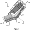
- FIGS. 4 and 5 illustrate views of a hearable device 400.
- the hearable device 400 is similar to the hearable device 200, but with a different design.
- the hearable device 400 may have the same or different functionalities as the hearable device 200.
- the hearable device 400 is shown without the encapsulant 230.
- the hearable device 400 may include the encapsulant 230.
- the hearable device 400 may have a length of about 2.4 centimeter (cm) or less, and a diameter of about 1.2 centimeter (cm) or less.
- the hearable device 400 is small enough to substantially fit in the ear canal of the outer ear.
- the hearable device 400 may have similar dimensions as the hearable device 200.
- the hearable device 400 includes the first board 202, the second board 204, the flex board 208, the power source 210, the first integrated device 212, the speaker 214, the microphone 216, the coil 218, and the second integrated device 220.
- the first board 202, the second board 204, the flex board 208, the first integrated device 212, the speaker 214, the microphone 216, the coil 218, and the second integrated device 220 are all located on one side of the power source 210.
- the first board 202 may be coupled to a first side of the flex board 208.
- the second board 204 may be coupled a second side of the flex board 208.
- the first integrated device 212 and/or the second integrated device 220 may be low power consumption processors, as described in FIG. 2 .
- the hearable device 400 may include one or more processors that draws about 5-2000 micro-Watts of power (e.g., processor power) and locally processes at least most of the audio data (e.g., audio CODEC).
- an ultra low power processor or a low power processor may be configured to use about 2 milli-Watts of power of less (5-2000 micro-Watts).
- one or more of the lower power processors described in the disclosure may operate at a clock rate or clock speed of about 30-50 megahertz (Mhz).
- the coil 218 is formed such that the coil 218 surrounds the first board 202, the second board 204, the flex board 208 and the microphone 216.
- the speaker 214, the microphone 216 and the power source 210 are coupled to the flex board 208.
- the flex board 208 is coupled to the first board 202 and the second board 204.
- the first integrated device 212 and the second integrated device 220 are coupled to the first board 202.
- the speaker 214, the microphone 216 and/or the power source 210 may be coupled to the first board 202 and/or the second board 204.
- the hearable device 400 may include other components and/or devices as described for the hearable device 200. These other components and/or devices (e.g., passive device, wireless communication device, CODEC device) may be coupled to the first board 202, the second board 204 and/or the flex board 208. These and other functionalities may be implemented in a single integrated device (e.g., SiP) or two or more integrated devices.
- these other components and/or devices e.g., passive device, wireless communication device, CODEC device
- CODEC device may be coupled to the first board 202, the second board 204 and/or the flex board 208.
- These and other functionalities may be implemented in a single integrated device (e.g., SiP) or two or more integrated devices.
- the hearable device 400 comprises a length of about 2.4 centimeters (cm) or less (e.g., about 1.8-2.4 centimeters), and a diameter of about 1.2 centimeters (cm) or less (e.g., about 1-1.2 centimeters) or a width and depth that is similar to about 1.2 centimeters (cm) or less (e.g., about 1-1.2 centimeters).
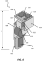
- FIG. 6 illustrates a view of a hearable device 600.
- the hearable device 600 is similar to the hearable device 200, but with a different design.
- the hearable device 600 may have the same or different functionalities as the hearable device 200.
- the hearable device 600 is shown without the encapsulant 230. However, in some implementations, the hearable device 600 may include the encapsulant 230.
- the hearable device 600 has a length of about 2.4 centimeters (cm) or less (e.g., about 1.8-2.4 centimeters), and a diameter of about 1.2 centimeters (cm) or less (e.g., about 1-1.2 centimeters).
- the hearable device 600 is small enough to substantially fit in the ear canal of the outer ear.
- the hearable device 600 includes a first board 602, a second board 604, a third board 606, a first flex board 608, a second flex board 618, a third flex board 628, a power source 610, a first integrated device 612, a second integrated device 620, the speaker 214 and the microphone 216.
- the first board 602 is coupled to the first flex board 608.
- the first flex board 608 is coupled to the second board 604.
- the second board 604 is coupled to the second flex board 618 and the third flex board 628.
- the second flex board 618 and the third flex board 628 are coupled to the third board 606.
- the flex board(s) e.g., 608, 618, 628) are flexible (e.g., bendable) such that the flex board(s) (608, 618, 628) are at least partially wrapped around the power source 610.
- at least one flex board e.g., 608, 618, 628) has a bend radius of 5 millimeters (mm) or less.
- At least one flex board may be flexible in such a way that the flex board can bend by at least 45 degrees or more (e.g., 45 degrees to 360 degrees).
- the flex board(s) e.g., 608, 618, 628) allows the hearable device 600 to have small form factor (e.g., volume) by allowing components to wrap around the power source 610 thereby saving a lot of space.
- the power source 610 includes a plurality of button cell batteries.
- the power source 610 is coupled to the second board 604, the first flex board 608 and the second flex board 618.
- the first flex board 608 and the second flex board 618 at least partially wrap around the power source 610.
- the speaker 214 is coupled to the first board 602.
- the first integrated device 612 is coupled to the third board 606.
- the first integrated device 612 may include a System in Package (SiP) that includes various functionalities.
- the first integrated device 612 may for example include a processor and/or a memory.
- the first integrated device 612 includes a communication device (e.g., Bluetooth device).
- the microphone 216 and the second integrated device 620 are coupled to the third board 606.
- the second integrated device 620 may include various functionalities, CODEC and/or power management. It is noted that in some implementations, the functionalities of the first integrated device 612 and the second integrated device 620 may be implemented in a same integrated device. Other components (e.g., passive device) may also be coupled to the boards.
- the first integrated device 612 and/or the second integrated device 620 may be low power consumption processors, as described in FIG. 2 .
- the hearable device 600 may include one or more processors that draws about 5-2000 micro-Watts of power (e.g., processor power) and locally processes at least most of the audio data (e.g., audio CODEC).
- an ultra low power processor or a low power processor may be configured to use about 2 milli-Watts of power of less (5-2000 micro-Watts).
- one or more of the lower power processors described in the disclosure may operate at a clock rate or clock speed of about 30-50 megahertz (Mhz).
- the first integrated device 612 is about 5 millimeters (mm) x 5 millimeters (mm) x 0.4 millimeters (mm), or less.
- the power source 610 e.g., battery
- the hearing source 610 is about 5.8 millimeters (mm) x 3.6 millimeters (mm), or less.
- different implementations may use components with different dimensions.
- the hearable device 600 may be modified to include other components and/or functionalities as described for the other hearable devices in the present disclosure.
- first integrated device 212 e.g., first integrated device 212, second integrated device 220, first integrated device 612, second integrated device 620
- integrated devices may be implemented in any of the hearable devices described in the present disclosure.
- integrated devices may also include different functionalities and/or capabilities.
- An integrated device may include a semiconductor device, an integrated circuit, a die, an interposer, a package or package-on-package (PoP), and/or a System-in-Package (SiP).
- PoP package or package-on-package
- SiP System-in-Package
- FIG. 7 illustrates an example of an integrated device 700 that may be implemented in a hearable device of the present disclosure.
- the integrated device 700 may be implemented as the first integrated device 212, the second integrated device 220, the first integrated device 612, and/ or the second integrated device 620.
- the integrated device 700 includes a substrate 702, a first die 704, a second die 706, a third die 708, a spacer 710 and an encapsulation layer 712.
- the substrate 702 includes one or more dielectric layers 720 and a plurality of interconnects 722.
- a plurality of solder interconnects 730 (e.g., solder balls) is coupled to the plurality of interconnects 722.
- the first die 704 is coupled to the substrate 702.
- the second die 706 is coupled (e.g., mounted over) the first die 704.
- the spacer 710 is coupled to the second die 706.
- the third die 708 is coupled (e.g., mounted over) the spacer 710.
- the second die 706 is electrically coupled to the substrate 702 through a plurality of first wire bonds 760.
- the third die 708 is electrically coupled to the substrate 702 through a plurality of second wire bonds 780.
- the encapsulation layer 712 at least partially encapsulates the first die 704, the second die 706, the third die 708 and the spacer 710.
- the encapsulation layer 712 may include a mold compound, an epoxy fill and/or a resin.
- FIG. 7 is merely an example of an integrated device. Different implementations may use integrated devices with different configurations and arrangements.
- the first die 704 includes a processor.
- the second die 706 includes a Bluetooth communication device.
- the third die 708 includes a memory device.
- a die may include a wireless charging functionality, near field communication (NFC) functionality and/or a CODEC functionality.
- NFC near field communication
- the integrated device 700 has dimensions of about 5 millimeters (mm) x 5 millimeters (mm) x 0.4 millimeters (mm), or less.
- the integrated device 700 is configured to use ultra-low power logic processors and ultra-lower power radios.
- processors based on advanced node CMOS such as 28 nm LP or 28 nm FD-SOI technology that enable ultra-lower power processors with 5-2000 micro-Watts of processor power consumption while supporting always-on functionality may be used for the integrated device 700.
- An example of a transistor for an low power processor is illustrated an described below in FIG. 8 .
- the availability of a ultra-low power processor within the hearable device enables data processing and signal processing to happen locally.
- a local ultra-low power processor With availability of a local ultra-low power processor most of the signal processing is done locally and only a small fraction of data is transmitted to the secondary device (e.g., phone).
- data transmission is done through radios designed at similarly ultra-low power advanced node CMOS are desired to keep leakage current draw to a minimum, have low power (sub-microWatt) wake-up circuits to support useful battery life.
- the second integrated device 220 may include one or more processors that draws about 5-2000 micro-Watts of power (e.g., processor power) and locally processes at least most of the audio data (e.g., audio CODEC).
- processors that draws about 5-2000 micro-Watts of power (e.g., processor power) and locally processes at least most of the audio data (e.g., audio CODEC).
- an ultra low power processor or a low power processor may be configured to use about 2 milli-Watts of power of less (e.g., 5-2000 micro-Watts).
- FIG. 8 illustrates a profile view of a transistor 800 that may be implemented in a low power processor.
- the transistor 800 may be implemented in the integrated device 700 of FIG. 7 and/or any other integrated devices described in the disclosure.
- the transistor 800 is an example of a transistor that uses a Fully Depleted Silicon on Insulator (FD-SOI) process.
- FD-SOI Fully Depleted Silicon on Insulator
- the transistor 800 includes a substrate 810, an oxide layer 820, a source 830, a drain 840, a silicon layer 850, and a gate 860.
- the source 830 and the drain 840 is formed in the substrate 810.
- the oxide layer 820 is a buried oxide in the substrate 810.
- the substrate 810 may be a silicon.
- the silicon layer 850 may be a thin film silicon layer formed over the substrate 810.
- the gate 860 is formed over the silicon layer 850.
- the transistor 800 enables a low power processor that uses about 5-2000 micro-Watts of processor power consumption while supporting always-on functionality.
- a low power processor may operate at a clock rate or clock speed of about 30-50 megahertz (MHz).
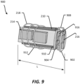
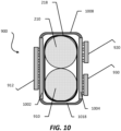
- FIGS. 9 and 10 illustrate views of a hearable device 900.
- the hearable device 900 is similar to the hearable device 200, but with a different design.
- the hearable device 900 may have the same or different functionalities as the hearable device 200.
- the hearable device 900 is shown without the encapsulant 230.
- the hearable device 900 may include the encapsulant 230.
- the hearable device 900 may have a length of about 2.4 centimeters (cm) or less (e.g., about 1.6 - 2.0 cm), and a diameter of about 1.2 centimeters (cm) or less (e.g., about 1 - 1.2 cm).
- different implementations may have different dimensions.
- the hearable device 900 is small enough to substantially fit in the ear canal of the outer ear.
- the hearable device 900 includes a first board 902, a second board 904, a third board 1002, a fourth board 1004, the power source 210, a power source 910, a first flex board 908, a second flex board 1008, a third flex board 1018, a first integrated device 912, a second integrated device 920, a third integrated device 930, one or more components 916 (e.g., surface mounted technology component), the speaker 214, the microphone 216 and the coil 218.
- a first board 902 a second board 904, a third board 1002, a fourth board 1004, the power source 210, a power source 910, a first flex board 908, a second flex board 1008, a third flex board 1018, a first integrated device 912, a second integrated device 920, a third integrated device 930, one or more components 916 (e.g., surface mounted technology component), the speaker 214, the microphone 216 and the coil 218.
- components 916 e.
- the first board 902 is coupled to the second board 904 through the first flex board 908.
- the microphone 216 is coupled to the first board 902.
- the one or more components 916 e.g., passive device are coupled to the second board 904.
- the third board 1002 is coupled to the fourth board 1004 through the second flex board 1008 and the third flex board 1018.
- the third board 1002, the fourth board 1004, the second flex board 1008 and the third flex board 1018 at least partially surround the power source 210 and the power source 910.
- the flex board(s) (e.g., 1008, 1018, 1028) allows the hearable device 900 to have a small form factor (e.g., volume) by allowing components to wrap around the power source(s) (e.g., 210, 910) thereby saving a lot of space.
- a small form factor e.g., volume
- the power source 210 and the power source 910 are configured to provide power to the first integrated device 912, the second integrated device 920, the third integrated device 930, the speaker 214 and the microphone 216.
- the speaker 214 and the first integrated device 912 are coupled to the third board 1002.
- the second integrated device 920 and the third integrated device 930 are coupled to the fourth board 1004.
- the functionalities of the first integrated device 912, the second integrated device 920 and/or the third integrated device 930 may be implemented in a same integrated device.
- the first integrated device 912, the second integrated device 920 and/or the third integrated device 930 may be low power consumption processors, as described in FIG. 2 .
- the hearable device 900 may include one or more processors that draws about 5-2000 micro-Watts of power (e.g., processor power) and locally processes at least most of the audio data (e.g., audio CODEC).
- an ultra low power processor or a low power processor may be configured to use about 2 milli-Watts of power of less (5-2000 micro-Watts).
- one or more of the lower power processors described in the disclosure may operate at a clock rate or clock speed of about 30-50 megahertz (Mhz).
- hearable device 900 may be modified to include other components and/or functionalities as described for the other hearable devices in the present disclosure.
- the various devices, components e.g., SMT components, passive devices
- the integrated devices may be coupled to the board(s) (e.g., first board 202, flex board 208) differently.
- the devices, components, and/or the integrated devices may be coupled to the board(s) through a plurality of solder interconnects (e.g., solder balls, copper pillars and solder).
- FIGS. 2-10 One or more of the components, processes, features, and/or functions illustrated in FIGS. 2-10 may be rearranged and/or combined into a single component, process, feature or function or embodied in several components, processes, or functions. Additional elements, components, processes, and/or functions may also be added without departing from the disclosure. It should also be noted FIGS. 2-10 and its corresponding description in the present disclosure is not limited to dies and/or ICs. In some implementations, FIGS. 2-10 and its corresponding description may be used to manufacture, create, provide, and/or produce devices and/or integrated devices.
- a device may include a hearable device, a die, an integrated device, a die package, an integrated circuit (IC), a device package, an integrated circuit (IC) package, a wafer, a semiconductor device, a package-on-package (PoP) device, and/or an interposer.
- IC integrated circuit
- IC integrated circuit
- IC integrated circuit
- PoP package-on-package
Landscapes
- Engineering & Computer Science (AREA)
- Physics & Mathematics (AREA)
- Signal Processing (AREA)
- Acoustics & Sound (AREA)
- Computer Networks & Wireless Communication (AREA)
- Neurosurgery (AREA)
- Otolaryngology (AREA)
- General Health & Medical Sciences (AREA)
- Health & Medical Sciences (AREA)
- Microelectronics & Electronic Packaging (AREA)
- Circuit For Audible Band Transducer (AREA)
- Telephone Set Structure (AREA)
- Charge And Discharge Circuits For Batteries Or The Like (AREA)
- Input Circuits Of Receivers And Coupling Of Receivers And Audio Equipment (AREA)
- Telephone Function (AREA)
- Electrophonic Musical Instruments (AREA)
- Mobile Radio Communication Systems (AREA)
- Details Of Audible-Bandwidth Transducers (AREA)
Claims (6)
- Vorrichtung, die Folgendes umfasst:eine erste, zweite und dritte Leiterplatte (602, 604, 606);ein erstes und zweites integriertes Bauelement (612, 620), die mit der dritten Leiterplatte (606) gekoppelt sind, wobei das erste integrierte Bauelement (612) Mittel zum Bereitstellen von drahtloser Kommunikation umfasst;Mittel (214) zum Erzeugen einer Schallwelle, wobei das Mittel zum Erzeugen einer Schallwelle mit der ersten Leiterplatte (602) gekoppelt ist;Mittel (216) zum Erfassen einer Schallwelle, wobei das Mittel zum Erfassen einer Schallwelle mit der dritten Leiterplatte (606) gekoppelt ist;Mittel (610) zum Versorgen des ersten und zweiten integrierten Bauelements, des Schallwellenerzeugungsmittels und des Schallwellenerfassungsmittels mit Strom, wobei das Stromversorgungsmittel mehrere Knopfzellenbatterien umfasst, einschließlich einer ersten und zweiten Knopfzellenbatterie, die voneinander beabstandet sind, undeine erste, zweite und dritte flexible Leiterplatte (608, 618, 628), die jeweils zumindest teilweise um eine Knopfzellenbatterie der mehreren Knopfzellenbatterien gewickelt sind, wobei jede flexible Leiterplatte eine oder mehrere Verbindungen aufweist, um elektrische Pfade zwischen zwei oder mehr Punkten oder Komponenten bereitzustellen,wobei die erste flexible Leiterplatte (608) mit der ersten und zweiten Leiterplatte (602, 604) gekoppelt ist,wobei die zweite und dritte flexible Leiterplatte (618, 628) jeweils sowohl mit der zweiten als auch mit der dritten Leiterplatte (604, 606) gekoppelt sind,wobei sich die erste Knopfzellenbatterie zwischen der ersten und zweiten Leiterplatte (602, 604) befindet, wobei die erste und zweite flexible Leiterplatte (608, 618) zumindest teilweise um die erste Knopfzellenbatterie gewickelt sind,wobei sich die zweite Knopfzellenbatterie zwischen der zweiten und dritten Leiterplatte (604, 606) befindet, wobei die dritte flexible Leiterplatte (628) zumindest teilweise um die zweite Knopfzellenbatterie gewickelt ist,wobei die Vorrichtung eine Länge von etwa 2,4 Zentimeter (cm) oder weniger und einen Durchmesser von etwa 1,2 Zentimeter (cm) oder weniger aufweist.
- Vorrichtung nach Anspruch 1, wobei das erste integrierte Bauelement einen Low-Power-Prozessor umfasst, der etwa 5 bis 2000 Mikrowatt Strom verbraucht.
- Vorrichtung nach Anspruch 1, wobei das Mittel zum Bereitstellen von drahtloser Kommunikation ein integriertes Bauelement umfasst, das zum Bereitstellen von drahtloser Bluetooth-Kommunikation konfiguriert ist.
- Vorrichtung nach Anspruch 1, das außerdem Mittel zum Speichern von Daten umfasst.
- Vorrichtung nach Anspruch 1, das außerdem Mittel zum Bereitstellen von magnetischer Nahfeldkommunikation (NFC) umfasst.
- Vorrichtung nach einem der vorherigen Ansprüche, wobei das erste integrierte Bauelement eine Grundfläche von 120 Quadratmillimetern oder weniger aufweist.
Applications Claiming Priority (4)
| Application Number | Priority Date | Filing Date | Title |
|---|---|---|---|
| US201662376738P | 2016-08-18 | 2016-08-18 | |
| US15/677,427 US11206499B2 (en) | 2016-08-18 | 2017-08-15 | Hearable device comprising integrated device and wireless functionality |
| PCT/US2017/047176 WO2018035242A1 (en) | 2016-08-18 | 2017-08-16 | Hearable device comprising integrated device and wireless functionality |
| EP17758371.3A EP3501181A1 (de) | 2016-08-18 | 2017-08-16 | Ohrhörer mit integrierter vorrichtung und drahtlosfunktion |
Related Parent Applications (1)
| Application Number | Title | Priority Date | Filing Date |
|---|---|---|---|
| EP17758371.3A Division EP3501181A1 (de) | 2016-08-18 | 2017-08-16 | Ohrhörer mit integrierter vorrichtung und drahtlosfunktion |
Publications (4)
| Publication Number | Publication Date |
|---|---|
| EP4002876A2 EP4002876A2 (de) | 2022-05-25 |
| EP4002876A3 EP4002876A3 (de) | 2022-08-24 |
| EP4002876B1 true EP4002876B1 (de) | 2025-03-12 |
| EP4002876C0 EP4002876C0 (de) | 2025-03-12 |
Family
ID=61192521
Family Applications (2)
| Application Number | Title | Priority Date | Filing Date |
|---|---|---|---|
| EP21217072.4A Active EP4002876B1 (de) | 2016-08-18 | 2017-08-16 | Ohrhörer mit integrierter vorrichtung und drahtlosfunktion |
| EP17758371.3A Withdrawn EP3501181A1 (de) | 2016-08-18 | 2017-08-16 | Ohrhörer mit integrierter vorrichtung und drahtlosfunktion |
Family Applications After (1)
| Application Number | Title | Priority Date | Filing Date |
|---|---|---|---|
| EP17758371.3A Withdrawn EP3501181A1 (de) | 2016-08-18 | 2017-08-16 | Ohrhörer mit integrierter vorrichtung und drahtlosfunktion |
Country Status (8)
| Country | Link |
|---|---|
| US (2) | US11206499B2 (de) |
| EP (2) | EP4002876B1 (de) |
| KR (2) | KR20190037263A (de) |
| CN (2) | CN109644300B (de) |
| AU (1) | AU2017313749B2 (de) |
| SG (1) | SG11201900186QA (de) |
| TW (1) | TWI814708B (de) |
| WO (1) | WO2018035242A1 (de) |
Families Citing this family (13)
| Publication number | Priority date | Publication date | Assignee | Title |
|---|---|---|---|---|
| SG157235A1 (en) | 2001-10-01 | 2009-12-29 | Entegris Inc | A thermoplastic heat exchanger and method of making the same |
| US7384149B2 (en) | 2003-07-21 | 2008-06-10 | Asml Netherlands B.V. | Lithographic projection apparatus, gas purging method and device manufacturing method and purge gas supply system |
| US11473945B2 (en) * | 2016-08-12 | 2022-10-18 | Brightsentinel Holding Ltd | Modular wireless sensing device |
| US11206499B2 (en) | 2016-08-18 | 2021-12-21 | Qualcomm Incorporated | Hearable device comprising integrated device and wireless functionality |
| DE102019207008A1 (de) * | 2019-05-14 | 2020-11-19 | Sivantos Pte. Ltd. | Hörinstrument |
| CN110149583A (zh) * | 2019-05-27 | 2019-08-20 | 深圳市中德听力技术有限公司 | 一种无线充电助听器 |
| EP3890353A1 (de) * | 2020-03-30 | 2021-10-06 | GN Hearing A/S | Hörgerät mit leiterplattenanordnung |
| EP3890352A1 (de) * | 2020-03-30 | 2021-10-06 | GN Hearing A/S | Hörgerät mit einer antenne |
| EP3890354A1 (de) * | 2020-03-30 | 2021-10-06 | GN Hearing A/S | Hörgerät mit leiterplattenanordnung und ausgangswandler |
| EP4311260A4 (de) * | 2021-06-28 | 2024-12-11 | Samsung Electronics Co., Ltd. | Elektronische vorrichtung |
| WO2023031187A1 (en) * | 2021-08-30 | 2023-03-09 | Sivantos Pte. Ltd. | Hearing device |
| WO2023033739A1 (en) * | 2021-08-30 | 2023-03-09 | Sivantos Pte. Ltd. | Temperature reduction for wireless charging |
| US20250039613A1 (en) * | 2021-12-10 | 2025-01-30 | Board Of Trustees Of Northern Illinois University | Flexible conductive hearing aids |
Family Cites Families (58)
| Publication number | Priority date | Publication date | Assignee | Title |
|---|---|---|---|---|
| FR2669802B1 (fr) * | 1990-11-23 | 1993-06-18 | Intrason France | Dispositif electronique formant prothese auditive programmable miniature, en particulier du type intra-conduit. |
| US5721783A (en) | 1995-06-07 | 1998-02-24 | Anderson; James C. | Hearing aid with wireless remote processor |
| US5789815A (en) * | 1996-04-23 | 1998-08-04 | Motorola, Inc. | Three dimensional semiconductor package having flexible appendages |
| US6456720B1 (en) * | 1999-12-10 | 2002-09-24 | Sonic Innovations | Flexible circuit board assembly for a hearing aid |
| US6940729B2 (en) * | 2001-10-26 | 2005-09-06 | Staktek Group L.P. | Integrated circuit stacking system and method |
| US8184839B2 (en) * | 2004-01-07 | 2012-05-22 | Etymotic Research, Inc. | One-size-fits-most hearing aid |
| JP2006100302A (ja) * | 2004-09-28 | 2006-04-13 | Sharp Corp | 高周波モジュールおよびその製造方法 |
| KR100795306B1 (ko) * | 2006-08-21 | 2008-01-15 | 권유정 | 귓속 보청기용 페이스 플레이트의 제조방법 |
| JP2008091554A (ja) * | 2006-09-29 | 2008-04-17 | Matsushita Electric Works Ltd | 音声出力装置 |
| WO2009023738A2 (en) * | 2007-08-14 | 2009-02-19 | Insound Medical, Inc. | Combined microphone and receiver assembly for extended wear canal hearing devices |
| US8670355B1 (en) * | 2007-10-18 | 2014-03-11 | At&T Mobility Ii Llc | System and method for network based hearing aid compatible mode selection |
| DE102007055385B4 (de) * | 2007-11-20 | 2009-12-03 | Siemens Medical Instruments Pte. Ltd. | Abschirmungseinrichtung für ein Hörhilfegerät |
| DE102008008897B3 (de) * | 2008-02-13 | 2009-07-30 | Siemens Medical Instruments Pte. Ltd. | Schaltung mit integrierter Abschirmung und Hörhilfe |
| US8415777B2 (en) * | 2008-02-29 | 2013-04-09 | Broadcom Corporation | Integrated circuit with millimeter wave and inductive coupling and methods for use therewith |
| US7652628B2 (en) | 2008-03-13 | 2010-01-26 | Sony Ericsson Mobile Communications Ab | Antenna for use in earphone and earphone with integrated antenna |
| US8363869B2 (en) * | 2008-05-12 | 2013-01-29 | Sonic Innovations, Inc. | Hearing aid housing apparatus |
| US8737658B2 (en) * | 2008-12-19 | 2014-05-27 | Starkey Laboratories, Inc. | Three dimensional substrate for hearing assistance devices |
| US8369553B2 (en) | 2008-12-19 | 2013-02-05 | Starkey Laboratories, Inc. | Hearing assistance device with stacked die |
| CN201383874Y (zh) * | 2009-03-03 | 2010-01-13 | 王勇 | 无线供电式蓝牙抗噪声助听器 |
| SG10201406058YA (en) | 2009-07-22 | 2014-11-27 | Aria Innovations Inc | Open ear canal hearing aid |
| DK2476266T3 (en) | 2009-09-08 | 2016-10-24 | Sivantos Pte Ltd | Hearing Aid with wireless battery charging capacity |
| CA2777601C (en) * | 2009-10-15 | 2016-06-21 | Widex A/S | A hearing aid with audio codec and method |
| US9615745B2 (en) * | 2009-11-25 | 2017-04-11 | The Brigham And Women's Hospital | System and method for wireless biosensor monitoring |
| EP2393308B1 (de) | 2010-06-07 | 2019-10-16 | Oticon A/s | Hörgerät mit einem gefalteten Substrat |
| US9602914B2 (en) * | 2010-08-27 | 2017-03-21 | Apple Inc. | Porting audio using a connector in a small form factor electronic device |
| US8478567B2 (en) | 2010-09-28 | 2013-07-02 | Qualcomm Incorporated | Systems and methods for measuring the effectiveness of a workload predictor on a mobile device |
| US20120089130A1 (en) * | 2010-10-06 | 2012-04-12 | Gyurik Robert J | Automatic electronic delivery of medication for veterinary and other uses |
| US9002049B2 (en) | 2010-10-08 | 2015-04-07 | Starkey Laboratories, Inc. | Housing for a standard fit hearing assistance device |
| US8929559B2 (en) * | 2011-03-01 | 2015-01-06 | Starkey Laboratories, Inc. | Method and apparatus for selecting right and left circuit configurations of hearing assistance devices |
| US8885860B2 (en) | 2011-06-02 | 2014-11-11 | The Regents Of The University Of California | Direct drive micro hearing device |
| US8761423B2 (en) | 2011-11-23 | 2014-06-24 | Insound Medical, Inc. | Canal hearing devices and batteries for use with same |
| US8831256B2 (en) * | 2011-12-09 | 2014-09-09 | Cochlear Limited | Controlling a link for different load conditions |
| DK2640095T4 (da) * | 2012-03-15 | 2020-12-21 | Sonova Ag | Metode til tilpasning af et høreapparat med aktiv okklusionskontrol til en bruger |
| US9223326B2 (en) | 2012-07-22 | 2015-12-29 | International Business Machines Corporation | Distributed thermal management system for servers |
| KR101476401B1 (ko) * | 2013-05-23 | 2014-12-23 | 주식회사 바이오사운드랩 | 일체형 전자부품 모듈을 갖는 보청기 |
| US9191757B2 (en) | 2013-07-11 | 2015-11-17 | Starkey Laboratories, Inc. | Hearing aid with inductively coupled electromagnetic resonator antenna |
| CN103781009A (zh) | 2014-01-29 | 2014-05-07 | 董永政 | 具有多功能线圈的蓝牙设备 |
| US10425724B2 (en) * | 2014-03-13 | 2019-09-24 | Starkey Laboratories, Inc. | Interposer stack inside a substrate for a hearing assistance device |
| KR20150111157A (ko) | 2014-03-25 | 2015-10-05 | 삼성전자주식회사 | 보청기의 소리를 조정하는 방법, 이를 수행하는 보청기 및 전자 장치 |
| KR101786879B1 (ko) * | 2014-04-30 | 2017-10-18 | 한국전기연구원 | 무선 전력 송신 장치, 무선 전력 수신 장치 및 코일 구조물 |
| US9491880B2 (en) * | 2014-08-12 | 2016-11-08 | Google Technology Holdings LLC | Circuit assembly for compact acoustic device |
| US10827283B2 (en) * | 2014-08-19 | 2020-11-03 | Starkey Laboratories, Inc. | Flexible hearing aid circuit with motherboard and peripheral attachments |
| DE102014217085A1 (de) | 2014-08-27 | 2016-03-03 | Sivantos Pte. Ltd. | Hörhilfegerät sowie Verfahren zum Betrieb des Hörhilfegeräts mit einer Kommunikationsvorrichtung |
| CN204316710U (zh) | 2015-01-06 | 2015-05-06 | 新速马(上海)电子科技发展有限公司 | 具有扩音助听器功能的蓝牙耳机 |
| EP3269153B1 (de) * | 2015-03-09 | 2019-05-22 | Sonova AG | Kanalhörgeräte mit verbesserten dichtungen |
| US10820844B2 (en) * | 2015-07-23 | 2020-11-03 | California Institute Of Technology | Canary on a chip: embedded sensors with bio-chemical interfaces |
| US10149635B2 (en) * | 2015-08-14 | 2018-12-11 | Massachusetts Institute Of Technology | Ingestible devices and methods for physiological status monitoring |
| US20170064830A1 (en) * | 2015-08-24 | 2017-03-02 | Motorola Mobility Llc | Circuit Assembly for Compact Acoustic Device |
| US9877119B2 (en) * | 2015-12-21 | 2018-01-23 | Gn Hearing A/S | Hearing aid with antenna on printed circuit board |
| DE102015226813A1 (de) | 2015-12-29 | 2017-06-29 | Sivantos Pte. Ltd. | Hörgerät |
| US10034105B2 (en) | 2016-01-04 | 2018-07-24 | Starkey Laboratories, Inc. | Article with internal light source for fitting in-situ and related devices and methods |
| US10345887B2 (en) | 2016-05-06 | 2019-07-09 | Mediatek Inc. | Adaptive optimization of low power strategies |
| US11206499B2 (en) | 2016-08-18 | 2021-12-21 | Qualcomm Incorporated | Hearable device comprising integrated device and wireless functionality |
| DE102016220432A1 (de) * | 2016-10-18 | 2018-04-19 | Sivantos Pte. Ltd. | Hörhilfegerät und Signalverarbeitungseinrichtung für ein Hörhilfegerät |
| US10811764B2 (en) * | 2017-03-03 | 2020-10-20 | Logitech Europe S.A. | Wireless wearable electronic device communicatively coupled to a remote device |
| DE112019003955T5 (de) * | 2018-08-06 | 2021-05-06 | Dopple Ip B.V. | Integrierte unterbaugruppe für eine tragbare audiovorrichtung |
| KR20230135153A (ko) * | 2018-10-08 | 2023-09-22 | 나노이어 코포레이션 인코포레이티드 | 소형 보청기 |
| EP3890352A1 (de) * | 2020-03-30 | 2021-10-06 | GN Hearing A/S | Hörgerät mit einer antenne |
-
2017
- 2017-08-15 US US15/677,427 patent/US11206499B2/en active Active
- 2017-08-16 WO PCT/US2017/047176 patent/WO2018035242A1/en not_active Ceased
- 2017-08-16 CN CN201780049750.XA patent/CN109644300B/zh active Active
- 2017-08-16 KR KR1020197004603A patent/KR20190037263A/ko not_active Ceased
- 2017-08-16 TW TW106127846A patent/TWI814708B/zh active
- 2017-08-16 SG SG11201900186QA patent/SG11201900186QA/en unknown
- 2017-08-16 EP EP21217072.4A patent/EP4002876B1/de active Active
- 2017-08-16 EP EP17758371.3A patent/EP3501181A1/de not_active Withdrawn
- 2017-08-16 AU AU2017313749A patent/AU2017313749B2/en active Active
- 2017-08-16 KR KR1020247007079A patent/KR20240034262A/ko active Pending
- 2017-08-16 CN CN202111050608.1A patent/CN113766401A/zh active Pending
-
2021
- 2021-11-02 US US17/517,439 patent/US11785399B2/en active Active
Also Published As
| Publication number | Publication date |
|---|---|
| KR20240034262A (ko) | 2024-03-13 |
| EP4002876A2 (de) | 2022-05-25 |
| US11785399B2 (en) | 2023-10-10 |
| US20180054682A1 (en) | 2018-02-22 |
| CN109644300B (zh) | 2021-09-17 |
| EP3501181A1 (de) | 2019-06-26 |
| EP4002876A3 (de) | 2022-08-24 |
| CN113766401A (zh) | 2021-12-07 |
| EP4002876C0 (de) | 2025-03-12 |
| US20220116717A1 (en) | 2022-04-14 |
| BR112019002745A2 (pt) | 2019-05-14 |
| WO2018035242A1 (en) | 2018-02-22 |
| AU2017313749B2 (en) | 2022-02-03 |
| TW201811067A (zh) | 2018-03-16 |
| KR20190037263A (ko) | 2019-04-05 |
| CN109644300A (zh) | 2019-04-16 |
| AU2017313749A1 (en) | 2019-01-31 |
| SG11201900186QA (en) | 2019-03-28 |
| US11206499B2 (en) | 2021-12-21 |
| TWI814708B (zh) | 2023-09-11 |
Similar Documents
| Publication | Publication Date | Title |
|---|---|---|
| US11785399B2 (en) | Hearable device comprising integrated device and wireless functionality | |
| US10872834B2 (en) | Integrated circuit structures with extended conductive pathways | |
| US10522454B2 (en) | Microelectronic package having a passive microelectronic device disposed within a package body | |
| US11424195B2 (en) | Microelectronic assemblies having front end under embedded radio frequency die | |
| JP5944490B2 (ja) | 無線・電磁干渉を遮蔽する積層ダイパッケージのシリコン貫通ビア、及びその製造方法 | |
| US11784143B2 (en) | Single metal cavity antenna in package connected to an integrated transceiver front-end | |
| US11887940B2 (en) | Integrated circuit packages with conductive element having cavities housing electrically connected embedded components | |
| US20190057940A1 (en) | Stairstep interposers with integrated shielding for electronics packages | |
| KR102108707B1 (ko) | 기판 내 커플링된 인덕터 구조 | |
| KR20160086759A (ko) | 오포섬-다이 패키지-온-패키지 장치 | |
| US20200365996A1 (en) | Package integrated cavity resonator antenna | |
| US20200176417A1 (en) | Stacked embedded passive substrate structure | |
| WO2018048450A1 (en) | Microelectronic structures having notched microelectronic substrates | |
| US10332671B2 (en) | Solenoid inductor | |
| CN103260125B (zh) | 芯片封装结构及其制造方法 | |
| HK40005088A (en) | Hearable device comprising integrated device and wireless functionality | |
| HK40005088B (zh) | 包括集成器件和无线功能性的可听设备 | |
| US20240222035A1 (en) | Package substrate embedded multi-layered in via capacitors | |
| BR112019002745B1 (pt) | Dispositivo audível compreendendo dispositivo integrado e funcionalidade sem fio | |
| US8581394B2 (en) | Semiconductor package module and electric circuit assembly with the same |
Legal Events
| Date | Code | Title | Description |
|---|---|---|---|
| PUAI | Public reference made under article 153(3) epc to a published international application that has entered the european phase |
Free format text: ORIGINAL CODE: 0009012 |
|
| STAA | Information on the status of an ep patent application or granted ep patent |
Free format text: STATUS: THE APPLICATION HAS BEEN PUBLISHED |
|
| AC | Divisional application: reference to earlier application |
Ref document number: 3501181 Country of ref document: EP Kind code of ref document: P |
|
| AK | Designated contracting states |
Kind code of ref document: A2 Designated state(s): AL AT BE BG CH CY CZ DE DK EE ES FI FR GB GR HR HU IE IS IT LI LT LU LV MC MK MT NL NO PL PT RO RS SE SI SK SM TR |
|
| PUAL | Search report despatched |
Free format text: ORIGINAL CODE: 0009013 |
|
| AK | Designated contracting states |
Kind code of ref document: A3 Designated state(s): AL AT BE BG CH CY CZ DE DK EE ES FI FR GB GR HR HU IE IS IT LI LT LU LV MC MK MT NL NO PL PT RO RS SE SI SK SM TR |
|
| RIC1 | Information provided on ipc code assigned before grant |
Ipc: H04R 25/00 20060101ALI20220722BHEP Ipc: H04R 1/10 20060101AFI20220722BHEP |
|
| STAA | Information on the status of an ep patent application or granted ep patent |
Free format text: STATUS: REQUEST FOR EXAMINATION WAS MADE |
|
| 17P | Request for examination filed |
Effective date: 20230224 |
|
| RBV | Designated contracting states (corrected) |
Designated state(s): AL AT BE BG CH CY CZ DE DK EE ES FI FR GB GR HR HU IE IS IT LI LT LU LV MC MK MT NL NO PL PT RO RS SE SI SK SM TR |
|
| GRAP | Despatch of communication of intention to grant a patent |
Free format text: ORIGINAL CODE: EPIDOSNIGR1 |
|
| STAA | Information on the status of an ep patent application or granted ep patent |
Free format text: STATUS: GRANT OF PATENT IS INTENDED |
|
| INTG | Intention to grant announced |
Effective date: 20241018 |
|
| GRAS | Grant fee paid |
Free format text: ORIGINAL CODE: EPIDOSNIGR3 |
|
| GRAA | (expected) grant |
Free format text: ORIGINAL CODE: 0009210 |
|
| STAA | Information on the status of an ep patent application or granted ep patent |
Free format text: STATUS: THE PATENT HAS BEEN GRANTED |
|
| AC | Divisional application: reference to earlier application |
Ref document number: 3501181 Country of ref document: EP Kind code of ref document: P |
|
| AK | Designated contracting states |
Kind code of ref document: B1 Designated state(s): AL AT BE BG CH CY CZ DE DK EE ES FI FR GB GR HR HU IE IS IT LI LT LU LV MC MK MT NL NO PL PT RO RS SE SI SK SM TR |
|
| REG | Reference to a national code |
Ref country code: GB Ref legal event code: FG4D |
|
| REG | Reference to a national code |
Ref country code: CH Ref legal event code: EP |
|
| REG | Reference to a national code |
Ref country code: DE Ref legal event code: R096 Ref document number: 602017088367 Country of ref document: DE |
|
| REG | Reference to a national code |
Ref country code: IE Ref legal event code: FG4D |
|
| U01 | Request for unitary effect filed |
Effective date: 20250326 |
|
| U07 | Unitary effect registered |
Designated state(s): AT BE BG DE DK EE FI FR IT LT LU LV MT NL PT RO SE SI Effective date: 20250402 |
|
| PG25 | Lapsed in a contracting state [announced via postgrant information from national office to epo] |
Ref country code: RS Free format text: LAPSE BECAUSE OF FAILURE TO SUBMIT A TRANSLATION OF THE DESCRIPTION OR TO PAY THE FEE WITHIN THE PRESCRIBED TIME-LIMIT Effective date: 20250612 |
|
| PG25 | Lapsed in a contracting state [announced via postgrant information from national office to epo] |
Ref country code: ES Free format text: LAPSE BECAUSE OF FAILURE TO SUBMIT A TRANSLATION OF THE DESCRIPTION OR TO PAY THE FEE WITHIN THE PRESCRIBED TIME-LIMIT Effective date: 20250312 |
|
| PG25 | Lapsed in a contracting state [announced via postgrant information from national office to epo] |
Ref country code: NO Free format text: LAPSE BECAUSE OF FAILURE TO SUBMIT A TRANSLATION OF THE DESCRIPTION OR TO PAY THE FEE WITHIN THE PRESCRIBED TIME-LIMIT Effective date: 20250612 |
|
| PG25 | Lapsed in a contracting state [announced via postgrant information from national office to epo] |
Ref country code: HR Free format text: LAPSE BECAUSE OF FAILURE TO SUBMIT A TRANSLATION OF THE DESCRIPTION OR TO PAY THE FEE WITHIN THE PRESCRIBED TIME-LIMIT Effective date: 20250312 |
|
| PG25 | Lapsed in a contracting state [announced via postgrant information from national office to epo] |
Ref country code: GR Free format text: LAPSE BECAUSE OF FAILURE TO SUBMIT A TRANSLATION OF THE DESCRIPTION OR TO PAY THE FEE WITHIN THE PRESCRIBED TIME-LIMIT Effective date: 20250613 |
|
| U20 | Renewal fee for the european patent with unitary effect paid |
Year of fee payment: 9 Effective date: 20250710 |
|
| PG25 | Lapsed in a contracting state [announced via postgrant information from national office to epo] |
Ref country code: SM Free format text: LAPSE BECAUSE OF FAILURE TO SUBMIT A TRANSLATION OF THE DESCRIPTION OR TO PAY THE FEE WITHIN THE PRESCRIBED TIME-LIMIT Effective date: 20250312 |
|
| PG25 | Lapsed in a contracting state [announced via postgrant information from national office to epo] |
Ref country code: PL Free format text: LAPSE BECAUSE OF FAILURE TO SUBMIT A TRANSLATION OF THE DESCRIPTION OR TO PAY THE FEE WITHIN THE PRESCRIBED TIME-LIMIT Effective date: 20250312 |
|
| PGFP | Annual fee paid to national office [announced via postgrant information from national office to epo] |
Ref country code: GB Payment date: 20250710 Year of fee payment: 9 |
|
| PG25 | Lapsed in a contracting state [announced via postgrant information from national office to epo] |
Ref country code: CZ Free format text: LAPSE BECAUSE OF FAILURE TO SUBMIT A TRANSLATION OF THE DESCRIPTION OR TO PAY THE FEE WITHIN THE PRESCRIBED TIME-LIMIT Effective date: 20250312 |
|
| PGFP | Annual fee paid to national office [announced via postgrant information from national office to epo] |
Ref country code: IE Payment date: 20250709 Year of fee payment: 9 |
|
| PG25 | Lapsed in a contracting state [announced via postgrant information from national office to epo] |
Ref country code: SK Free format text: LAPSE BECAUSE OF FAILURE TO SUBMIT A TRANSLATION OF THE DESCRIPTION OR TO PAY THE FEE WITHIN THE PRESCRIBED TIME-LIMIT Effective date: 20250312 |
|
| PG25 | Lapsed in a contracting state [announced via postgrant information from national office to epo] |
Ref country code: IS Free format text: LAPSE BECAUSE OF FAILURE TO SUBMIT A TRANSLATION OF THE DESCRIPTION OR TO PAY THE FEE WITHIN THE PRESCRIBED TIME-LIMIT Effective date: 20250712 |