EP4002785A1 - Apparatus for signal detection using gaussian frequency shift keying transmission and a method using the apparatus - Google Patents
Apparatus for signal detection using gaussian frequency shift keying transmission and a method using the apparatus Download PDFInfo
- Publication number
- EP4002785A1 EP4002785A1 EP21159638.2A EP21159638A EP4002785A1 EP 4002785 A1 EP4002785 A1 EP 4002785A1 EP 21159638 A EP21159638 A EP 21159638A EP 4002785 A1 EP4002785 A1 EP 4002785A1
- Authority
- EP
- European Patent Office
- Prior art keywords
- frequency offset
- estimation unit
- sub
- signal
- signal detection
- Prior art date
- Legal status (The legal status is an assumption and is not a legal conclusion. Google has not performed a legal analysis and makes no representation as to the accuracy of the status listed.)
- Granted
Links
Images


Classifications
-
- H—ELECTRICITY
- H04—ELECTRIC COMMUNICATION TECHNIQUE
- H04L—TRANSMISSION OF DIGITAL INFORMATION, e.g. TELEGRAPHIC COMMUNICATION
- H04L27/00—Modulated-carrier systems
- H04L27/10—Frequency-modulated carrier systems, i.e. using frequency-shift keying
- H04L27/106—M-ary FSK
-
- H—ELECTRICITY
- H04—ELECTRIC COMMUNICATION TECHNIQUE
- H04L—TRANSMISSION OF DIGITAL INFORMATION, e.g. TELEGRAPHIC COMMUNICATION
- H04L25/00—Baseband systems
- H04L25/02—Details ; arrangements for supplying electrical power along data transmission lines
- H04L25/03—Shaping networks in transmitter or receiver, e.g. adaptive shaping networks
- H04L25/03006—Arrangements for removing intersymbol interference
- H04L25/03178—Arrangements involving sequence estimation techniques
- H04L25/03305—Joint sequence estimation and interference removal
-
- H—ELECTRICITY
- H04—ELECTRIC COMMUNICATION TECHNIQUE
- H04L—TRANSMISSION OF DIGITAL INFORMATION, e.g. TELEGRAPHIC COMMUNICATION
- H04L27/00—Modulated-carrier systems
- H04L27/10—Frequency-modulated carrier systems, i.e. using frequency-shift keying
- H04L27/14—Demodulator circuits; Receiver circuits
-
- H—ELECTRICITY
- H04—ELECTRIC COMMUNICATION TECHNIQUE
- H04L—TRANSMISSION OF DIGITAL INFORMATION, e.g. TELEGRAPHIC COMMUNICATION
- H04L27/00—Modulated-carrier systems
- H04L27/10—Frequency-modulated carrier systems, i.e. using frequency-shift keying
- H04L27/16—Frequency regulation arrangements
Definitions
- N a number of at most N ⁇ 0 falsely decided symbols may still indicate a detected signal.
- N identifies the maximum allowed number of falsely decided symbols for a receiver to assume that the transmitted packet was correctly detected.
- Bluetooth Core Specification Version 5.2, 2019-12-31, Bluetooth Special Interest Group Key parameters driving Bluetooth and Bluetooth Low Energy (see Bluetooth Core Specification Version 5.2, 2019-12-31, Bluetooth Special Interest Group ) receiver advancement are low power consumption, high sensitivity and robustness against interference. When operating at the sensitivity limit, retransmissions happen, meaning that higher sensitivity converts again into a power consumption advantage due to less retransmissions.
- the inventive apparatus comprises an interference construction unit configured to calculate modulation symbols x 0 ... x M out of known sequence bits b -1 ...b M sent by the transmitter and known to the receiver and to construct inter-symbol interference terms c 0 ... c M-1 with M ⁇ 0 presenting the length of the known sequence, whereas the interference construction unit is connected to the signal detection unit and the frequency offset estimation unit for inputting the inter-symbol interference terms c 0 . .. c M-1 to the signal detection unit and the modulation symbols x 0 ...
Landscapes
- Engineering & Computer Science (AREA)
- Computer Networks & Wireless Communication (AREA)
- Signal Processing (AREA)
- Power Engineering (AREA)
- Digital Transmission Methods That Use Modulated Carrier Waves (AREA)
- Noise Elimination (AREA)
Abstract
Description
- The invention discloses an apparatus for improved signal detection embedded within a receiver configured to receive signal packets sent by a transmitter using Gaussian Frequency Shift Keying, GSFK, the apparatus comprises a signal detection unit being fed with a signal y(t) from a frequency demodulator in the receiver, a frequency offset estimation unit configured to estimate a frequency offset between a local oscillator of the transmitter and a local oscillator of the receiver and a timing estimation unit configured to estimate a time position where an expected signal was detected at the receiver.
- The invention also discloses a method for improved signal detection, which is performed by the inventive apparatus.
- Frequency shift keying (FSK) is a modulation technique to transmit digital signals via a radio channel. It is related to analog frequency modulation and, like it, is insensitive to interference. Gaussian Frequency Shift Keying is an FSK method with an upstream Gaussian filter. This flattens the steep edges of digital signals, which means that the highfrequency components of the signal are eliminated. As a result, less bandwidth is required for the transmission of the signal. The Gaussian filter has the advantage of reducing sideband power, reducing interference with neighboring channels, but at the cost of increasing inter-symbol interference.
- An abstract model of a Gaussian Frequency Shift Keying (GFSK) transmission is shown in figure 1a.
- A series of symbols x(k)∈{-1,1} 1 is transmitted, another symbol after every T seconds. Transmitted symbols/values {-1,1} correspond to data bit values {0,1}, part of which are expected to be received as a known sequence of bits b0 ... bM-1. The terms known sequence of bits, known sequence bits and known sequence are used synonymously. The instantaneous-frequency signal f(t) = Σ kx(k) · g(t - k·T) 3 is composed of superimposed weighted and time-shifted impulses, where g(t) 2 is a convolution of a length-T rectangular pulse with a Gaussian pulse. Integration 4 of this instantaneous-frequency signal yields the instantaneous phase ϕ(t) 5 which modulates a rotating exponential 6, i. e., the transmitted signal is s(t) =
e -i2π∫∑kx(k)·g(t-k-)dt 7. Afrequency offset Δf 8 by ej2πΔf.t is applied and white Gaussian noise n(t) 9 is added to obtain the received signal r(t) = s(t) . ej2πΔf.t + n(t) 10. A lowpass filter h(t) 11 removes interference and reduces the noise bandwidth, providing the signal rh(t) = r(t)*h(t) 12. Thefrequency demodulator 13 computes the derivative of the phase

post-filter 15 yields the noise-reduced continuous-time signal y(t) = f̃(t) *p(t) 16, which is sampled every T seconds to obtain the received symbols y(k) = y(k·T) 17. y(t) is the input signal to the apparatus. It is a signal internal to the receiver (after filtering, frequency demodulation, and another filtering). The transmission chain according to figure 1a includes transmitter, channel, and receiver. r(t) is the received signal. So, y(t) is the frequency demodulator post-filter output, which is fed into the signal detector. A post-filter can be part of a general frequency demodulator. - In a Bluetooth and Bluetooth Low Energy modem a Gaussian Frequency Shift Keying (GFSK) modulation is applied. A GSFK receiver first performs non-data-aided frequency offset estimation by a frequency offset estimator and detects the received packet using the given frequency offset estimate by performing sequential symbol-by-symbol decisions before shifting the signal bit-wise in a delay line of bits and checking whether the expected symbol sequence was found. This detection happens at an over-sampled rate, and if the detector finds the expected symbol sequence at multiple successive sample times, the receiver utilizes the middle position of these occasions as the best sample position. As defined in the Bluetooth Standard for the particular transmission scheme, e. g., Bluetooth Basic Rate, a number of at most N ≥ 0 falsely decided symbols may still indicate a detected signal. N identifies the maximum allowed number of falsely decided symbols for a receiver to assume that the transmitted packet was correctly detected.
Figure 3 shows schematically the known art signal detection circuit. A perfect match between the transmitted signal and the known sequence bits would be at N=0. - Key parameters driving Bluetooth and Bluetooth Low Energy (see Bluetooth Core Specification Version 5.2, 2019-12-31, Bluetooth Special Interest Group) receiver advancement are low power consumption, high sensitivity and robustness against interference. When operating at the sensitivity limit, retransmissions happen, meaning that higher sensitivity converts again into a power consumption advantage due to less retransmissions.
- Reception starts with the detection of a transmitted packet. A transmitted Bluetooth packet begins with a so-called access code. Upon reception of this access code the receiver is entitled to receive the actual payload data. Undetected packets may need to be re-transmitted, causing a penalty in energy consumption. There is a need for highly sensitive and robust packet detection to minimize packet loss. However, inter-symbol interference as well as time or frequency synchronization error, jointly called parameter estimation errors, degrade the performance of the packet detection.
- So, it is an objective of the present invention to present an apparatus and a method that determines the inter-symbol interference pattern caused by a known transmitted signal portion and cancels it out during packet detection in order to improve the reliability of the symbol decision.
- It is also an objective of the present invention to make use of the known, expected, transmitted signal portion to estimate synchronization parameters, i. e., to perform a data-aided joint signal detection and parameter estimation in order to reduce parameter estimation errors that degrade the performance of the packet detection.
- The objective of the present invention is solved by an apparatus according to the
independent claim 1. - The inventive apparatus comprises an interference construction unit configured to calculate modulation symbols x0 ...xM out of known sequence bits b-1...bM sent by the transmitter and known to the receiver and to construct inter-symbol interference terms c0 ...cM-1 with M≥0 presenting the length of the known sequence, whereas the interference construction unit is connected to the signal detection unit and the frequency offset estimation unit for inputting the inter-symbol interference terms c0...cM-1 to the signal detection unit and the modulation symbols x0 ...xM-1 to both the signal detection unit and the frequency offset estimation unit, whereas outputs of the signal detection unit and the frequency offset estimation unit are connected to a modulation amplitude estimation unit and the timing estimation unit for estimating and outputting estimations of the frequency offset Δf̃s , the time offset t̃s , and a modulation amplitude

- A key idea of this inventive apparatus is to determine a symbol interference pattern caused by a known transmitted signal portion between a transmitter and a receiver and cancel said symbol interference pattern out during packet detection on receiver side, which includes symbol decisions, whereat the interference cancellation improves the reliability of the symbol decisions. A further key idea is to make use of the known, expected, transmitted signal portion to estimate synchronization parameters, i. e., to perform a data-aided joint signal detection and parameter estimation. These estimated parameters include the frequency offset Δf̃s, time offset t̃s , and a modulation amplitude

The abstract model of the Gaussian Frequency Shift Keying (GFSK) transmission shown in figure 1a can be simplified by an idealized equivalent discrete-time model shown in figure 1b. The transfer function is simplified into

frequency offset Δf 8, the third term the received data symbol x(k) 1, and the last term identifies interference from neighboring symbols, x(m≠k). m is an auxiliary index used to indicate all other indices except k. In practice, only a few neighbors will be incorporated. The transmitter sends the payload data embedded in packets, and a packet consists of a sequence known 22 to the receiver followed by unknown information, which is shown infigure 2a . y(k) is used to receive the unknown information of a transmitted packet and only used to show how the discrete-time model is linked with the continuous-time model of figure 1a. - As an example, in Bluetooth (BT) or Bluetooth Low Energy (BLE) the known sequence must be used to determine whether a receiving device is the intended addressee of the sent information. Furthermore, the GFSK modulation index must fall within a limited range of values, which is [0.28; 0.35] for Bluetooth and [0.45; 0.55] for Bluetooth Low Energy. The terms GFSK modulation index and modulation index are used synonymously. The term modulation index describes a property of the transmitted signal.
-
Figure 2b shows a typical GFSK packet receiver. Theantenna 43 receives a radio frequency signal. Thedown converter 44 transforms the radio frequency signal into a baseband signal. Thefrequency demodulator 45 delivers an estimated instantaneous frequency as its output signal. The "known signal"detector 46 detects presence of an expected signal and estimates synchronization parameters, based upon thefrequency demodulator 45 output signal and, optionally and dependent on the specific implementation, its input signal. The "unknown information"detection unit 47 estimates and decides upon received information bits in the received signal, based upon synchronization parameters obtained from the "known signal"detector 46. - The inventive apparatus differs from known receivers which uses GFSK modulation for signal detection at least in the interference construction unit and a modified signal detection unit. Furthermore, these new means require adaptations to known units of a receiver using GFSK as being claimed in the dependent claims.
- In a variant of the inventive apparatus, the interference construction unit comprises inputs of g(-L) · a0 and g(L) · a0 which are used to weight and to calculate the inter-symbol interference terms C0 ...CM-1 from the known sequence bits b0...bM which are mapped to the modulation symbols x0 ...xM, whereas a0 is an assumed modulation amplitude value.
- The interference construction unit performs a mapping of the known sequence bits b0 ...bM to their symbols {-1;1} resulting in modulation symbols x0 ...xM . These modulation symbols X0 ...XM are weighted by sample pulses g(-1) and g(1), which are both multiplied by the assumed modulation amplitude value a0 . The reason for using a modulation amplitude value here is that the parameter includes receiver properties, specifically the scaling introduced by the filter p(t). The sum of the left and right side of the modulation response results in the inter-symbol interference terms c0 ...cM-1. These inter-symbol interference terms c0 ...cM-1 are fed to the signal detection unit. The modulation symbols x0 ...xM-1 are fed to the signal detection unit as well as to the frequency offset estimation unit.
- In a variant of the inventive apparatus, the assumed modulation amplitude value a0 is a mid-value of a modulation amplitude range corresponding to a modulation index range, as the mid value is most representative for the range of possible values.
- In another variant of the inventive apparatus, the signal detection unit comprises an input configured to feed the calculated inter-symbol interference terms c0 ...cM-1, an input configured to feed the modulation symbols x0 ...x M-1 and an input configured to feed a mean value of the frequency offset

- When receiving the (noisy) expected known sequence bits b0 ...bM inside a packet sent by the transmitter, the received samples are delayed by a delay line of samples, where the amount of inter-symbol interference terms c0 ...cM-1 caused by the known expected sequence bits b0... bM-1 is subtracted at each tap output. The difference between multiple delayed versions of the continuous time signal y(t-mT), m=0..M-1, and the inter-symbol interference terms c0 ...cM-1 results in difference terms d0 ...dM -1 representing a received signal travelling through the delay line, which is used together with the estimated frequency offset

- In another further variant of the inventive apparatus, the frequency offset estimation unit comprises an input configured to feed the modulation symbols x0 ...xM-1 and an input configured to feed difference terms d0 ...dM-1, which present a difference between delayed versions of the continuous time signal, y(t-mT), T being the symbol interval of sent modulation symbols, and the inter-symbol interference terms c0 ...c M-1 for estimating and outputting a mean value of the frequency offset

- So, after the apparatus has determined the expected noiseless received symbol sequence from the known sequence of bits using the modulation symbols x0 ...xM-1 and the mid-value ao of the modulation index range, it subtracts it from the received signal d0 ...d M-1 travelling through the delay line, and averages the difference in order to obtain the mean value of the frequency offset estimate,

- According to a variant of the inventive apparatus, the modulation amplitude estimation unit comprises an input configured to feed interference-free and frequency-offset-free symbols u0 ...uM-1 multiplied by constant-modulus values of the modulation symbols X0 ...XM-1 belonging to the known sequence bits b0 ...bM for estimating a mean value of the modulation amplitude ã(t).
- The modulation amplitude ã(t) is estimated by flipping the signs of interference-free and frequency-offset-free symbols according to the modulation symbols x 0··· x M-1 belonging to the known sequence and then averaging the result, u 0··· u M-1 . The interference-free and frequency-offset-free symbols u0 ...uM-1 are fed to the modulation amplitude estimation unit after calculated in the signal detection unit.
- According to another variant of the inventive apparatus, the timing estimation unit comprises inputs configured to feed the estimated modulation amplitude ã(t), the frequency offset


- The receiver obtains a timing estimate ãs by determining among the time positions where the known sequence was detected the particular time position t̃s , which yields the largest modulation amplitude. It also samples the time-varying frequency offset estimate at this time position to deliver an initial frequency offset estimate

- The inventive apparatus can be preferably used within a Bluetooth (BT) receiver or a Bluetooth Low Energy (BLE) receiver. Bluetooth and Bluetooth Low Energy utilize a known signal portion as an access code. This is different from a correlation sequence in the requirement to detect all (or most) symbols of the access code correctly in order to assume to be the addressee of a packet. In contrast, the purpose of a correlation sequence is only to synchronize.
- The objective of the present invention is also solved by a method for improved signal detection within a receiver according to
independent claim 8. The method is performed by the apparatus according to the apparatus claims. - The inventive method comprises the following steps:
- constructing inter-symbol interferences terms c0 ...c M-1 of an interference signal and modulation symbols x0 ...x M-1 out of a known sequence of bits b0 ...bM performed by the interference construction unit,
- estimating a frequency offset

- detecting presence of the known sequence of bits by the signal detection unit and
- simultaneously estimating a modulation amplitude ã(t) by the modulation amplitude estimation unit,
- and estimating a frequency offset Δf̃s , a time offset t̃s , and a modulation amplitude

- In a variant of the inventive method, the synchronization parameters are determined where the modulation amplitude becomes maximal, i. e., where the best similarity of the received signal to the expected known signal is found. The expected known signal is equal to the known sequence of bits, as the signal is derived from the sequence, or in other words, the transmitter converts the sequence into a continuous signal.
- Benefits of the invention are high sensitivity of packet detection as well as accurate parameter estimation. In addition, the robustness in interference scenarios, such as co-channel interference and adjacent channel interference is better than state-of-the-art.
- The invention will be explained in more detail using exemplary embodiments.
- The appended drawings show
- Fig. 1
-
- a) GFSK Transmission Chain Model (prior art),
- b) simplified GFSK Model (according to the invention);
- Fig. 2
- a) Transmitted packet (prior art); b) Packet receiver (prior art);
- Fig. 3
- Signal Detection (prior art);
- Fig. 4
- Apparatus for signal detection according to the invention;
- Fig. 5
- Interference construction unit;
- Fig. 6
- Signal detection unit;
- Fig. 7
- Frequency offset estimation unit;
- Fig. 8
- Modulation amplitude estimation unit;
- Fig. 9
- Timing estimation unit.
-
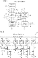
Figure 4 illustrates schematically the inventive apparatus for an improved signal detection within a receiver using Gaussian Frequency Shift Keying (GFSK). The apparatus comprises asignal detection unit 28 which is fed with a signal y(t) from the frequency demodulation in the receiver. Furthermore, it comprises aninterference construction unit 25, a frequency offsetestimation unit 31 configured to estimate a frequency offset Δf between a local oscillator of the transmitter and a local oscillator of the receiver, atiming estimation unit 35 configured to estimate a time position where an expected signal was detected at the receiver and a modulationamplitude estimation unit 33. Theinterference construction unit 25 transfers estimated inter-symbol interference terms c0 ...cM-1 26 and known modulation symbols x0 ...xM-1 27 to thesignal detection unit 28. It also transfers the modulation symbols x0 ...xM-1 27 to the frequency offsetestimation unit 31, which estimates a mean value of the frequency offset

signal detection unit 28. Thesignal detection unit 28 outputs difference terms d0 ...dM-1 30), which present a difference between a delayed continuous time signal y(t) and inter-symbol interference terms C0...C M-1 26 for estimating the frequency offset
estimation unit 31. Thesignal detection unit 28 further outputs interference-free and frequency-offset-free symbols u0 ...u M-1 29 and the detectedsequence 24. The symbols u0 ...uM-1 29 are transferred to the modulationamplitude estimation unit 33 for estimation the mean value of the modulation amplitude ã(t) 34. The detected sequence as well as the mean value of the modulation amplitude ã(t) 34 and the frequency offset
estimation unit 31 are transferred to thetiming estimation unit 35 for estimation of the synchronization parameters 36: the frequency offset Δf̃s , the time offset

synchronization parameters 36 may be utilized to optimize the process in subsequent demodulation of the unknown data as well. -
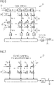
Figure 5 shows a detailed view of theinterference construction unit 25. The known expected sequence ofbits sample pulses 42 are both multiplied by the mid-value a0 of the modulation index range. For example, for calculation c1 the weighted modulation symbols x0 and x2 are needed. The sum of the left and right side of the modulation response results in the inter-symbol interference terms c0 ...c M-1 26. These inter-symbol interference terms c0 ...c M-1 26 are fed to thesignal detection unit 28. -
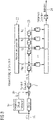
Figure 6 shows thesignal detection unit 28, which is fed with a continuous time signal y(t) from the frequency demodulator in the receiver, which is delayed by a delay line of samples 39. Continuous symbols are delayed by T, 2T, 3T, ..., (M-1) T. The amount of inter-symbol interference c0 ...c M-1 26 caused by the known expected sequence b0...b M-1 37 is subtracted at each tap output/bit-to-symbol mapping 38, assuming L=1 infigure 5 . This yields in the adifference 30 between the delayed continuous time signal y(t) and the inter-symbol interference terms c0 ...cM-1 26 from which a mean value of the frequency offset
u M-1 29. Comparing these symbols with zero performs hard decision on the symbols and indicates the position of mismatches against the known sequence. If the sum of the mismatches is smaller or equal than a pre-defined maximum number N of falsely decided symbols, then the received sequence is detected 24 to be correct. The flipped signs of interference-free and frequency-offset-free symbols u0 ...uM-1 29 are transferred to the modulationamplitude estimation unit 33 shown infigure 8 . -
Figure 7 shows the frequency offsetestimation unit 31. It receives the modulation symbols x0 ...x M-1 27 from theinterference construction unit 25, which are weighted by the mid-value a0 of the modulation index range. The result is subtracted from the difference terms d0 ...d M-1 30, which corresponds to the received signal travelling through the delay line of samples 39 respectively. These differences are averaged in order to obtain the mean value of the frequency-offset estimate,

signal detection unit 28. -
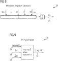
Figure 8 shows the modulationamplitude estimation unit 33. It uses the interference-free, frequency-offset-free, and sign-flipped symbols u0 ...uM-1 29 to calculate or to estimate a mean value of the modulation amplitude ã(t) 34. The modulation amplitude ã(t) 25 is transferred to thetiming estimation unit 35 shown infigure 9 . - The
timing estimation unit 35 infigure 9 is used to output estimations of the frequency offset Δf̃s , the time offset t̃s , and the modulation amplitude
synchronization parameters 36. The receiver obtains a timing estimate ãs by determining among the time positions where the known sequence was detected 24 the particular time position t̃s , which yields the largest modulation amplitude. It also samples the time-varying frequency offset estimate at this time position to deliver an initial frequency offset estimate
- In a practical implementation the continuous-time description above is replaced by processing at discrete time steps with oversampling relative to the
symbol rate 1/T. - Alternative implementations of the present inventive apparatus may use only a subset of the included estimators, by utilizing estimates from alternative estimator structures. For example, if another frequency-offset estimator is available, one may discard the related functionality in above described apparatus. One may also omit timing estimation related functionality if another means for this is available. One may drop modulation amplitude and timing estimation functionality if other means for both are available, or if the receiver does not make use of amplitude estimation while means for timing estimation are already available.
- Parameters may be different compared to the illustration above, in particular there may be L > 1.
-
- 1
- Transmitted series of symbols
- 2
- Convolution pulse
- 3
- Instantaneous frequency signal
- 4
- Integration
- 5
- Instantaneous phase
- 6
- Modulation of the transmitted signal
- 7
- Transmitted signal
- 8
- Frequency offset between transmitter and receiver
- 9
- White Gaussian noise
- 10
- Received signal
- 11
- Lowpass filter
- 12
- Signal with removed interference and reduced noise
- 13
- Frequency demodulator
- 14
- Estimated instantaneous frequency
- 15
- Post-filter
- 16
- Noise-reduced continuous-time signal
- 17
- Received symbols
- 18
- Continuous-time signal
- 19
- Frequency offset estimator
- 20
- Frequency offset estimate
- 21
- Symbol-by-symbol decision
- 22
- Known sequence of bits
- 23
- Delay-line of bits
- 24
- "Sequence detected" indication
- 25
- Interference construction unit
- 26
- Estimated interference sequence c0...cM-1
- 27
- Known symbol sequence x0...xM-1
- 28
- Signal detection unit
- 29
- Sequence of sign-flipped estimated symbols u0...uM-1
- 30
- Interference-removed symbol sequence d0...d M-1
- 31
- frequency offset estimation unit
- 32
- Estimated frequency offset

- 33
- Modulation amplitude estimation unit
- 34
- Estimated modulation amplitude ã(t)
- 35
- Timing estimation unit
- 36
- Estimated synchronization parameters
- 37
- Known sequence bits b0...bM
- 38
- Bit-to-symbol mapping
- 39
- Delay-line of signals
- 40
- Discrete-time impulse response
- 41
- Sequence of noise samples
- 42
- Interference terms of equivalent discrete-time impulse response
- 43
- Antenna
- 44
- Down converter
- 45
- frequency demodulator
- 46
- known signal detector
- 47
- unknown information detection unit
Claims (10)
- An apparatus embedded within a receiver configured to receive signal packets sent by a transmitter using Gaussian Frequency Shift Keying, GSFK, the apparatus comprises a signal detection unit (28) being fed with a signal y(t) from a frequency demodulator in the receiver, a frequency offset estimation unit (31) configured to estimate a frequency offset Δf between a local oscillator of the transmitter and a local oscillator of the receiver and a timing estimation unit (35) configured to estimate a time position where an expected signal was detected at the receiver, characterized in, that the apparatus comprises an interference construction unit (25) configured to calculate modulation symbols x0 ...xM (27) out of known sequence bits b0 ...bM (37) sent by the transmitter and known to the receiver and to construct inter-symbol interference terms c0 ...c M-1 (26) with M ≥ 0 presenting the length of the known sequence, whereas the interference construction unit (25) is connected to the signal detection unit (28) and the frequency offset estimation unit (31) for inputting the inter-symbol interference terms c0 ...cM-1 (26) to the signal detection unit (28) and the modulation symbols x0 ...xM (27) to the signal detection unit (28) and the frequency offset estimation unit (31), whereas outputs of the signal detection unit (28) and the frequency offset estimation unit (31) are connected to a modulation amplitude estimation unit (33) and the timing estimation unit (35) for calculating and outputting estimations of the frequency offset Δf̃s , the time offset t̃s , and a modulation amplitude

- The apparatus according to claim 1, characterized in, that the interference construction unit (25) comprises inputs (42) of g(-L) • a0 and g(L) • a0 which are used to weight and calculate the inter-symbol interference terms c0 ...cM-1 (26) with the known sequence bits b0 ...bM (37) mapped to the modulation symbols x0 ...xM (27), whereas a0 is an assumed modulation amplitude value.
- The apparatus according to claim 2, characterized in, that the assumed modulation amplitude value a0 is a mid-value of a modulation amplitude range corresponding to a modulation index range.
- The apparatus according to claim 1, characterized in, that the signal detection unit (28) comprises an input configured to feed the calculated inter-symbol interference terms c0 ...cM-1 (26), an input configured to feed the modulation symbols x0 ...xM-1 (27) and an input configured to feed the frequency offset

- The apparatus according to claim 1, characterized in, that the frequency offset estimation unit (31) comprises an input configured to feed the modulation symbols x0 ...xM-1 (27) and an input configured to feed difference terms d0...dM-1 (30), which present a difference between delayed versions of the continuous time signal, y(t-mT), T being a symbol interval of sent modulated symbols, and the inter-symbol interference terms c0 ...cM-1 (26) for estimating and outputting a mean value of the frequency offset

- The apparatus according to claim 1, characterized in, that the modulation amplitude estimation unit (33) comprises an input configured to feed interference-free and frequency-offset-free symbols u0 ...uM-1 (29) multiplied by the constant-modulus values of the modulation symbols x0 ...xM-1 (27) belonging to the known sequence bits b0 ...bM (37) for estimating a mean value of the modulation amplitude ã(t) (34).
- The apparatus according to claim 1, characterized in, that the timing estimation unit (35) comprises inputs configured to feed the estimated modulation amplitude ã(t) (34), frequency offset


- The apparatus according to one of the claims 1 to 7, the apparatus is used within a Bluetooth, BT, receiver or a Bluetooth Low Energy, BLE, receiver.
- A method for signal detection within a receiver, which is performed by the apparatus according to claims 1 to 8, wherein the method comprising the following steps:- constructing inter-symbol interferences terms c0 ...cM-1 (26) of an interference signal and modulation symbols x0 ...xM-1 (27) out of a known sequence of bits b0 ...bM (37) performed by the interference construction unit (25),- estimating a frequency offset by using the modulation symbols x0 ...xM-1 (27) and difference terms d0...dM-1 (30) which considers the interference signal,- detecting presence of the known sequence of bits (37) by the signal detection unit (28) and- simultaneously estimating a modulation amplitude ã(t) (24) by the modulation amplitude estimation unit (33),- and estimating a frequency offset Δf̃s , a time offset t̃s , and a modulation amplitude

- The method according to claim 9, characterized in, that the synchronization parameters (36) are determined where the modulation amplitude becomes maximal.
Priority Applications (2)
| Application Number | Priority Date | Filing Date | Title |
|---|---|---|---|
| PCT/EP2021/081199 WO2022106273A1 (en) | 2020-11-17 | 2021-11-10 | Apparatus for signal detection using gaussian frequency shift keying transmission and a method using the apparatus |
| CN202180044008.6A CN115735356A (en) | 2020-11-17 | 2021-11-10 | Apparatus for signal detection using gaussian frequency shift keying transmission and method using the same |
Applications Claiming Priority (1)
| Application Number | Priority Date | Filing Date | Title |
|---|---|---|---|
| EP20208105 | 2020-11-17 |
Publications (2)
| Publication Number | Publication Date |
|---|---|
| EP4002785A1 true EP4002785A1 (en) | 2022-05-25 |
| EP4002785B1 EP4002785B1 (en) | 2023-08-09 |
Family
ID=74797842
Family Applications (1)
| Application Number | Title | Priority Date | Filing Date |
|---|---|---|---|
| EP21159638.2A Active EP4002785B1 (en) | 2020-11-17 | 2021-02-26 | Apparatus for signal detection using gaussian frequency shift keying transmission and a method using the apparatus |
Country Status (3)
| Country | Link |
|---|---|
| EP (1) | EP4002785B1 (en) |
| CN (1) | CN115735356A (en) |
| WO (1) | WO2022106273A1 (en) |
Cited By (2)
| Publication number | Priority date | Publication date | Assignee | Title |
|---|---|---|---|---|
| US20220116760A1 (en) * | 2021-12-24 | 2022-04-14 | Michael Bogdanov | Mechanism for detecting attacks on frequency offset in a wireless network |
| EP4407939A1 (en) * | 2023-01-27 | 2024-07-31 | Samsung Electronics Co., Ltd. | Method of performing synchronization and frequency offset estimation using isi considered reference signal and receiver performing the same |
Families Citing this family (1)
| Publication number | Priority date | Publication date | Assignee | Title |
|---|---|---|---|---|
| US12278724B2 (en) * | 2023-04-25 | 2025-04-15 | Airoha Technology Corp. | Method and apparatus for estimating frequency offset through accumulating complete frequency deviation values of samples obtained from sampling frequency-modulated repetition-coded segment of packet |
Citations (1)
| Publication number | Priority date | Publication date | Assignee | Title |
|---|---|---|---|---|
| US20170195150A1 (en) * | 2015-12-30 | 2017-07-06 | Abov Semiconductor Co., Ltd | Bluetooth signal receiving method and device using improved symbol timing offset compensation |
Family Cites Families (3)
| Publication number | Priority date | Publication date | Assignee | Title |
|---|---|---|---|---|
| KR102041342B1 (en) * | 2017-07-24 | 2019-11-06 | 어보브반도체 주식회사 | Method for simultaneously performing packet detection, symbol timing acquisition and carrier frequency offset estimation using multiple correlation detection and bluetooth apparatus using the same |
| CN109286589B (en) * | 2018-10-16 | 2021-07-16 | 安徽传矽微电子有限公司 | Frequency offset estimator and method for GFSK demodulator |
| CN111147406B (en) * | 2019-12-06 | 2022-08-05 | 上海航天电子有限公司 | ASM system demodulation method based on constant false alarm signal detection and frequency offset correction |
-
2021
- 2021-02-26 EP EP21159638.2A patent/EP4002785B1/en active Active
- 2021-11-10 WO PCT/EP2021/081199 patent/WO2022106273A1/en not_active Ceased
- 2021-11-10 CN CN202180044008.6A patent/CN115735356A/en active Pending
Patent Citations (1)
| Publication number | Priority date | Publication date | Assignee | Title |
|---|---|---|---|---|
| US20170195150A1 (en) * | 2015-12-30 | 2017-07-06 | Abov Semiconductor Co., Ltd | Bluetooth signal receiving method and device using improved symbol timing offset compensation |
Non-Patent Citations (1)
| Title |
|---|
| QURESHI S U H: "ADAPTIVE EQUALIZATION", PROCEEDINGS OF THE IEEE, IEEE. NEW YORK, US, vol. 73, no. 9, 1 September 1985 (1985-09-01), pages 1349 - 1387, XP000608510, ISSN: 0018-9219 * |
Cited By (3)
| Publication number | Priority date | Publication date | Assignee | Title |
|---|---|---|---|---|
| US20220116760A1 (en) * | 2021-12-24 | 2022-04-14 | Michael Bogdanov | Mechanism for detecting attacks on frequency offset in a wireless network |
| US12452637B2 (en) * | 2021-12-24 | 2025-10-21 | Intel Corporation | Mechanism for detecting attacks on frequency offset in a wireless network |
| EP4407939A1 (en) * | 2023-01-27 | 2024-07-31 | Samsung Electronics Co., Ltd. | Method of performing synchronization and frequency offset estimation using isi considered reference signal and receiver performing the same |
Also Published As
| Publication number | Publication date |
|---|---|
| WO2022106273A1 (en) | 2022-05-27 |
| CN115735356A (en) | 2023-03-03 |
| EP4002785B1 (en) | 2023-08-09 |
Similar Documents
| Publication | Publication Date | Title |
|---|---|---|
| EP4002785B1 (en) | Apparatus for signal detection using gaussian frequency shift keying transmission and a method using the apparatus | |
| KR102041342B1 (en) | Method for simultaneously performing packet detection, symbol timing acquisition and carrier frequency offset estimation using multiple correlation detection and bluetooth apparatus using the same | |
| EP1197050B1 (en) | Synchronisation and detection of modulation type | |
| US20020094048A1 (en) | Synchronization signal detector and method | |
| US10015029B2 (en) | Bluetooth signal receiving method and device using improved symbol timing offset compensation | |
| JP5171291B2 (en) | Wireless transmission method, wireless transmission device, and wireless reception device | |
| US9722845B2 (en) | Bluetooth low energy frequency offset and modulation index estimation | |
| EP3549269B1 (en) | Digital radio communication | |
| US8379764B2 (en) | Receiving device and channel estimation method | |
| US10855499B2 (en) | Demodulator for use in radio communication receivers | |
| US6891905B1 (en) | Apparatus and method for FSK demodulation with integrated time and frequency tracking | |
| CN113115430A (en) | High-speed burst digital demodulation system | |
| EP1463233A2 (en) | Signal transmission method for frame formatted data using a unique word | |
| CN101060509B (en) | Symbol timing detector and wireless terminal | |
| CN104092527A (en) | GMSK coherent demodulation stream processing synchronization method combined with difference | |
| JPH06205062A (en) | Delay detection circuit | |
| US7046743B2 (en) | Demodulator for demodulating digital modulated signals | |
| CN108900281A (en) | A kind of method of the outer time delay of estimate symbol | |
| US7035352B1 (en) | Apparatus and method for signal acquisition in a FSK demodulator with integrated time and frequency tracking | |
| KR100653181B1 (en) | Non-coherent synchronous direct conversion receiver with frequency offset compensation | |
| US9059835B1 (en) | Method and apparatus for demodulating a wireless signal | |
| EP4055788B1 (en) | Digital receiver with phase offset compensation | |
| JP3973332B2 (en) | Digital modulation / demodulation synchronization system | |
| CN108923886A (en) | A kind of unique code type detection method | |
| JP3689043B2 (en) | Method for estimating frequency shift of CPFSK signal |
Legal Events
| Date | Code | Title | Description |
|---|---|---|---|
| PUAI | Public reference made under article 153(3) epc to a published international application that has entered the european phase |
Free format text: ORIGINAL CODE: 0009012 |
|
| STAA | Information on the status of an ep patent application or granted ep patent |
Free format text: STATUS: THE APPLICATION HAS BEEN PUBLISHED |
|
| AK | Designated contracting states |
Kind code of ref document: A1 Designated state(s): AL AT BE BG CH CY CZ DE DK EE ES FI FR GB GR HR HU IE IS IT LI LT LU LV MC MK MT NL NO PL PT RO RS SE SI SK SM TR |
|
| STAA | Information on the status of an ep patent application or granted ep patent |
Free format text: STATUS: REQUEST FOR EXAMINATION WAS MADE |
|
| 17P | Request for examination filed |
Effective date: 20221118 |
|
| RBV | Designated contracting states (corrected) |
Designated state(s): AL AT BE BG CH CY CZ DE DK EE ES FI FR GB GR HR HU IE IS IT LI LT LU LV MC MK MT NL NO PL PT RO RS SE SI SK SM TR |
|
| GRAP | Despatch of communication of intention to grant a patent |
Free format text: ORIGINAL CODE: EPIDOSNIGR1 |
|
| STAA | Information on the status of an ep patent application or granted ep patent |
Free format text: STATUS: GRANT OF PATENT IS INTENDED |
|
| RIC1 | Information provided on ipc code assigned before grant |
Ipc: H04L 27/16 20060101ALN20230331BHEP Ipc: H04L 27/10 20060101ALI20230331BHEP Ipc: H04L 25/03 20060101ALI20230331BHEP Ipc: H04L 27/14 20060101AFI20230331BHEP |
|
| INTG | Intention to grant announced |
Effective date: 20230504 |
|
| GRAJ | Information related to disapproval of communication of intention to grant by the applicant or resumption of examination proceedings by the epo deleted |
Free format text: ORIGINAL CODE: EPIDOSDIGR1 |
|
| STAA | Information on the status of an ep patent application or granted ep patent |
Free format text: STATUS: REQUEST FOR EXAMINATION WAS MADE |
|
| GRAP | Despatch of communication of intention to grant a patent |
Free format text: ORIGINAL CODE: EPIDOSNIGR1 |
|
| STAA | Information on the status of an ep patent application or granted ep patent |
Free format text: STATUS: GRANT OF PATENT IS INTENDED |
|
| GRAS | Grant fee paid |
Free format text: ORIGINAL CODE: EPIDOSNIGR3 |
|
| GRAA | (expected) grant |
Free format text: ORIGINAL CODE: 0009210 |
|
| STAA | Information on the status of an ep patent application or granted ep patent |
Free format text: STATUS: THE PATENT HAS BEEN GRANTED |
|
| INTC | Intention to grant announced (deleted) | ||
| RIC1 | Information provided on ipc code assigned before grant |
Ipc: H04L 27/16 20060101ALN20230612BHEP Ipc: H04L 27/10 20060101ALI20230612BHEP Ipc: H04L 25/03 20060101ALI20230612BHEP Ipc: H04L 27/14 20060101AFI20230612BHEP |
|
| INTG | Intention to grant announced |
Effective date: 20230627 |
|
| RIN1 | Information on inventor provided before grant (corrected) |
Inventor name: BURY, ANDREAS GERHARD |
|
| AK | Designated contracting states |
Kind code of ref document: B1 Designated state(s): AL AT BE BG CH CY CZ DE DK EE ES FI FR GB GR HR HU IE IS IT LI LT LU LV MC MK MT NL NO PL PT RO RS SE SI SK SM TR |
|
| REG | Reference to a national code |
Ref country code: GB Ref legal event code: FG4D |
|
| REG | Reference to a national code |
Ref country code: CH Ref legal event code: EP |
|
| REG | Reference to a national code |
Ref country code: IE Ref legal event code: FG4D |
|
| REG | Reference to a national code |
Ref country code: DE Ref legal event code: R096 Ref document number: 602021004052 Country of ref document: DE |
|
| REG | Reference to a national code |
Ref country code: LT Ref legal event code: MG9D |
|
| REG | Reference to a national code |
Ref country code: NL Ref legal event code: MP Effective date: 20230809 |
|
| REG | Reference to a national code |
Ref country code: AT Ref legal event code: MK05 Ref document number: 1598777 Country of ref document: AT Kind code of ref document: T Effective date: 20230809 |
|
| PG25 | Lapsed in a contracting state [announced via postgrant information from national office to epo] |
Ref country code: GR Free format text: LAPSE BECAUSE OF FAILURE TO SUBMIT A TRANSLATION OF THE DESCRIPTION OR TO PAY THE FEE WITHIN THE PRESCRIBED TIME-LIMIT Effective date: 20231110 |
|
| PG25 | Lapsed in a contracting state [announced via postgrant information from national office to epo] |
Ref country code: IS Free format text: LAPSE BECAUSE OF FAILURE TO SUBMIT A TRANSLATION OF THE DESCRIPTION OR TO PAY THE FEE WITHIN THE PRESCRIBED TIME-LIMIT Effective date: 20231209 |
|
| PG25 | Lapsed in a contracting state [announced via postgrant information from national office to epo] |
Ref country code: SE Free format text: LAPSE BECAUSE OF FAILURE TO SUBMIT A TRANSLATION OF THE DESCRIPTION OR TO PAY THE FEE WITHIN THE PRESCRIBED TIME-LIMIT Effective date: 20230809 Ref country code: RS Free format text: LAPSE BECAUSE OF FAILURE TO SUBMIT A TRANSLATION OF THE DESCRIPTION OR TO PAY THE FEE WITHIN THE PRESCRIBED TIME-LIMIT Effective date: 20230809 Ref country code: PT Free format text: LAPSE BECAUSE OF FAILURE TO SUBMIT A TRANSLATION OF THE DESCRIPTION OR TO PAY THE FEE WITHIN THE PRESCRIBED TIME-LIMIT Effective date: 20231211 Ref country code: NO Free format text: LAPSE BECAUSE OF FAILURE TO SUBMIT A TRANSLATION OF THE DESCRIPTION OR TO PAY THE FEE WITHIN THE PRESCRIBED TIME-LIMIT Effective date: 20231109 Ref country code: NL Free format text: LAPSE BECAUSE OF FAILURE TO SUBMIT A TRANSLATION OF THE DESCRIPTION OR TO PAY THE FEE WITHIN THE PRESCRIBED TIME-LIMIT Effective date: 20230809 Ref country code: LV Free format text: LAPSE BECAUSE OF FAILURE TO SUBMIT A TRANSLATION OF THE DESCRIPTION OR TO PAY THE FEE WITHIN THE PRESCRIBED TIME-LIMIT Effective date: 20230809 Ref country code: LT Free format text: LAPSE BECAUSE OF FAILURE TO SUBMIT A TRANSLATION OF THE DESCRIPTION OR TO PAY THE FEE WITHIN THE PRESCRIBED TIME-LIMIT Effective date: 20230809 Ref country code: IS Free format text: LAPSE BECAUSE OF FAILURE TO SUBMIT A TRANSLATION OF THE DESCRIPTION OR TO PAY THE FEE WITHIN THE PRESCRIBED TIME-LIMIT Effective date: 20231209 Ref country code: HR Free format text: LAPSE BECAUSE OF FAILURE TO SUBMIT A TRANSLATION OF THE DESCRIPTION OR TO PAY THE FEE WITHIN THE PRESCRIBED TIME-LIMIT Effective date: 20230809 Ref country code: GR Free format text: LAPSE BECAUSE OF FAILURE TO SUBMIT A TRANSLATION OF THE DESCRIPTION OR TO PAY THE FEE WITHIN THE PRESCRIBED TIME-LIMIT Effective date: 20231110 Ref country code: FI Free format text: LAPSE BECAUSE OF FAILURE TO SUBMIT A TRANSLATION OF THE DESCRIPTION OR TO PAY THE FEE WITHIN THE PRESCRIBED TIME-LIMIT Effective date: 20230809 Ref country code: AT Free format text: LAPSE BECAUSE OF FAILURE TO SUBMIT A TRANSLATION OF THE DESCRIPTION OR TO PAY THE FEE WITHIN THE PRESCRIBED TIME-LIMIT Effective date: 20230809 |
|
| PG25 | Lapsed in a contracting state [announced via postgrant information from national office to epo] |
Ref country code: PL Free format text: LAPSE BECAUSE OF FAILURE TO SUBMIT A TRANSLATION OF THE DESCRIPTION OR TO PAY THE FEE WITHIN THE PRESCRIBED TIME-LIMIT Effective date: 20230809 |
|
| PG25 | Lapsed in a contracting state [announced via postgrant information from national office to epo] |
Ref country code: ES Free format text: LAPSE BECAUSE OF FAILURE TO SUBMIT A TRANSLATION OF THE DESCRIPTION OR TO PAY THE FEE WITHIN THE PRESCRIBED TIME-LIMIT Effective date: 20230809 |
|
| PG25 | Lapsed in a contracting state [announced via postgrant information from national office to epo] |
Ref country code: SM Free format text: LAPSE BECAUSE OF FAILURE TO SUBMIT A TRANSLATION OF THE DESCRIPTION OR TO PAY THE FEE WITHIN THE PRESCRIBED TIME-LIMIT Effective date: 20230809 Ref country code: RO Free format text: LAPSE BECAUSE OF FAILURE TO SUBMIT A TRANSLATION OF THE DESCRIPTION OR TO PAY THE FEE WITHIN THE PRESCRIBED TIME-LIMIT Effective date: 20230809 Ref country code: ES Free format text: LAPSE BECAUSE OF FAILURE TO SUBMIT A TRANSLATION OF THE DESCRIPTION OR TO PAY THE FEE WITHIN THE PRESCRIBED TIME-LIMIT Effective date: 20230809 Ref country code: EE Free format text: LAPSE BECAUSE OF FAILURE TO SUBMIT A TRANSLATION OF THE DESCRIPTION OR TO PAY THE FEE WITHIN THE PRESCRIBED TIME-LIMIT Effective date: 20230809 Ref country code: DK Free format text: LAPSE BECAUSE OF FAILURE TO SUBMIT A TRANSLATION OF THE DESCRIPTION OR TO PAY THE FEE WITHIN THE PRESCRIBED TIME-LIMIT Effective date: 20230809 Ref country code: CZ Free format text: LAPSE BECAUSE OF FAILURE TO SUBMIT A TRANSLATION OF THE DESCRIPTION OR TO PAY THE FEE WITHIN THE PRESCRIBED TIME-LIMIT Effective date: 20230809 Ref country code: SK Free format text: LAPSE BECAUSE OF FAILURE TO SUBMIT A TRANSLATION OF THE DESCRIPTION OR TO PAY THE FEE WITHIN THE PRESCRIBED TIME-LIMIT Effective date: 20230809 |
|
| PGFP | Annual fee paid to national office [announced via postgrant information from national office to epo] |
Ref country code: DE Payment date: 20240219 Year of fee payment: 4 |
|
| REG | Reference to a national code |
Ref country code: DE Ref legal event code: R097 Ref document number: 602021004052 Country of ref document: DE |
|
| PG25 | Lapsed in a contracting state [announced via postgrant information from national office to epo] |
Ref country code: IT Free format text: LAPSE BECAUSE OF FAILURE TO SUBMIT A TRANSLATION OF THE DESCRIPTION OR TO PAY THE FEE WITHIN THE PRESCRIBED TIME-LIMIT Effective date: 20230809 |
|
| PLBE | No opposition filed within time limit |
Free format text: ORIGINAL CODE: 0009261 |
|
| STAA | Information on the status of an ep patent application or granted ep patent |
Free format text: STATUS: NO OPPOSITION FILED WITHIN TIME LIMIT |
|
| 26N | No opposition filed |
Effective date: 20240513 |
|
| PG25 | Lapsed in a contracting state [announced via postgrant information from national office to epo] |
Ref country code: SI Free format text: LAPSE BECAUSE OF FAILURE TO SUBMIT A TRANSLATION OF THE DESCRIPTION OR TO PAY THE FEE WITHIN THE PRESCRIBED TIME-LIMIT Effective date: 20230809 |
|
| PG25 | Lapsed in a contracting state [announced via postgrant information from national office to epo] |
Ref country code: MC Free format text: LAPSE BECAUSE OF FAILURE TO SUBMIT A TRANSLATION OF THE DESCRIPTION OR TO PAY THE FEE WITHIN THE PRESCRIBED TIME-LIMIT Effective date: 20230809 |
|
| REG | Reference to a national code |
Ref country code: CH Ref legal event code: PL |
|
| PG25 | Lapsed in a contracting state [announced via postgrant information from national office to epo] |
Ref country code: LU Free format text: LAPSE BECAUSE OF NON-PAYMENT OF DUE FEES Effective date: 20240226 |
|
| PG25 | Lapsed in a contracting state [announced via postgrant information from national office to epo] |
Ref country code: CH Free format text: LAPSE BECAUSE OF NON-PAYMENT OF DUE FEES Effective date: 20240229 |
|
| PG25 | Lapsed in a contracting state [announced via postgrant information from national office to epo] |
Ref country code: LU Free format text: LAPSE BECAUSE OF NON-PAYMENT OF DUE FEES Effective date: 20240226 Ref country code: CH Free format text: LAPSE BECAUSE OF NON-PAYMENT OF DUE FEES Effective date: 20240229 |
|
| PG25 | Lapsed in a contracting state [announced via postgrant information from national office to epo] |
Ref country code: BG Free format text: LAPSE BECAUSE OF FAILURE TO SUBMIT A TRANSLATION OF THE DESCRIPTION OR TO PAY THE FEE WITHIN THE PRESCRIBED TIME-LIMIT Effective date: 20230809 |
|
| PG25 | Lapsed in a contracting state [announced via postgrant information from national office to epo] |
Ref country code: BG Free format text: LAPSE BECAUSE OF FAILURE TO SUBMIT A TRANSLATION OF THE DESCRIPTION OR TO PAY THE FEE WITHIN THE PRESCRIBED TIME-LIMIT Effective date: 20230809 |
|
| REG | Reference to a national code |
Ref country code: BE Ref legal event code: MM Effective date: 20240229 |
|
| PG25 | Lapsed in a contracting state [announced via postgrant information from national office to epo] |
Ref country code: BE Free format text: LAPSE BECAUSE OF NON-PAYMENT OF DUE FEES Effective date: 20240229 |
|
| PG25 | Lapsed in a contracting state [announced via postgrant information from national office to epo] |
Ref country code: FR Free format text: LAPSE BECAUSE OF NON-PAYMENT OF DUE FEES Effective date: 20240229 |
|
| PG25 | Lapsed in a contracting state [announced via postgrant information from national office to epo] |
Ref country code: IE Free format text: LAPSE BECAUSE OF NON-PAYMENT OF DUE FEES Effective date: 20240226 |
|
| PG25 | Lapsed in a contracting state [announced via postgrant information from national office to epo] |
Ref country code: IE Free format text: LAPSE BECAUSE OF NON-PAYMENT OF DUE FEES Effective date: 20240226 Ref country code: FR Free format text: LAPSE BECAUSE OF NON-PAYMENT OF DUE FEES Effective date: 20240229 Ref country code: BE Free format text: LAPSE BECAUSE OF NON-PAYMENT OF DUE FEES Effective date: 20240229 |
|
| PG25 | Lapsed in a contracting state [announced via postgrant information from national office to epo] |
Ref country code: CY Free format text: LAPSE BECAUSE OF FAILURE TO SUBMIT A TRANSLATION OF THE DESCRIPTION OR TO PAY THE FEE WITHIN THE PRESCRIBED TIME-LIMIT; INVALID AB INITIO Effective date: 20210226 |
|
| REG | Reference to a national code |
Ref country code: DE Ref legal event code: R119 Ref document number: 602021004052 Country of ref document: DE |
|
| PG25 | Lapsed in a contracting state [announced via postgrant information from national office to epo] |
Ref country code: HU Free format text: LAPSE BECAUSE OF FAILURE TO SUBMIT A TRANSLATION OF THE DESCRIPTION OR TO PAY THE FEE WITHIN THE PRESCRIBED TIME-LIMIT; INVALID AB INITIO Effective date: 20210226 |
|
| GBPC | Gb: european patent ceased through non-payment of renewal fee |
Effective date: 20250226 |
|
| PG25 | Lapsed in a contracting state [announced via postgrant information from national office to epo] |
Ref country code: TR Free format text: LAPSE BECAUSE OF FAILURE TO SUBMIT A TRANSLATION OF THE DESCRIPTION OR TO PAY THE FEE WITHIN THE PRESCRIBED TIME-LIMIT Effective date: 20230809 |
|
| PG25 | Lapsed in a contracting state [announced via postgrant information from national office to epo] |
Ref country code: DE Free format text: LAPSE BECAUSE OF NON-PAYMENT OF DUE FEES Effective date: 20250902 |
|
| PG25 | Lapsed in a contracting state [announced via postgrant information from national office to epo] |
Ref country code: GB Free format text: LAPSE BECAUSE OF NON-PAYMENT OF DUE FEES Effective date: 20250226 |