EP4002733A1 - Physical uplink shared channel with hybrid automatic repeat request acknowledgement - Google Patents
Physical uplink shared channel with hybrid automatic repeat request acknowledgement Download PDFInfo
- Publication number
- EP4002733A1 EP4002733A1 EP21195427.6A EP21195427A EP4002733A1 EP 4002733 A1 EP4002733 A1 EP 4002733A1 EP 21195427 A EP21195427 A EP 21195427A EP 4002733 A1 EP4002733 A1 EP 4002733A1
- Authority
- EP
- European Patent Office
- Prior art keywords
- pusch
- dci
- harq
- wireless device
- network node
- Prior art date
- Legal status (The legal status is an assumption and is not a legal conclusion. Google has not performed a legal analysis and makes no representation as to the accuracy of the status listed.)
- Withdrawn
Links
- 238000000034 method Methods 0.000 claims abstract description 100
- 230000005540 biological transmission Effects 0.000 claims abstract description 85
- 238000012545 processing Methods 0.000 claims abstract description 79
- 238000004891 communication Methods 0.000 description 82
- 238000010586 diagram Methods 0.000 description 20
- 230000008569 process Effects 0.000 description 19
- 230000006870 function Effects 0.000 description 14
- 238000013507 mapping Methods 0.000 description 13
- 230000000737 periodic effect Effects 0.000 description 11
- 238000004590 computer program Methods 0.000 description 10
- 230000001413 cellular effect Effects 0.000 description 7
- 238000005259 measurement Methods 0.000 description 7
- 238000010397 one-hybrid screening Methods 0.000 description 6
- 238000003860 storage Methods 0.000 description 6
- 230000008901 benefit Effects 0.000 description 5
- 230000003287 optical effect Effects 0.000 description 5
- 230000011664 signaling Effects 0.000 description 5
- 230000004044 response Effects 0.000 description 4
- 230000000977 initiatory effect Effects 0.000 description 3
- 238000001514 detection method Methods 0.000 description 2
- 230000007774 longterm Effects 0.000 description 2
- 239000011159 matrix material Substances 0.000 description 2
- 238000012986 modification Methods 0.000 description 2
- 230000004048 modification Effects 0.000 description 2
- 230000007480 spreading Effects 0.000 description 2
- 238000003892 spreading Methods 0.000 description 2
- 230000008859 change Effects 0.000 description 1
- 230000001143 conditioned effect Effects 0.000 description 1
- 230000009977 dual effect Effects 0.000 description 1
- 230000005670 electromagnetic radiation Effects 0.000 description 1
- 230000006698 induction Effects 0.000 description 1
- 238000005304 joining Methods 0.000 description 1
- 238000004519 manufacturing process Methods 0.000 description 1
- 238000010295 mobile communication Methods 0.000 description 1
- 238000012544 monitoring process Methods 0.000 description 1
- 230000004043 responsiveness Effects 0.000 description 1
- 230000002441 reversible effect Effects 0.000 description 1
- 238000001228 spectrum Methods 0.000 description 1
- 238000012360 testing method Methods 0.000 description 1
- 238000012546 transfer Methods 0.000 description 1
- 230000003245 working effect Effects 0.000 description 1
Images


Classifications
-
- H—ELECTRICITY
- H04—ELECTRIC COMMUNICATION TECHNIQUE
- H04L—TRANSMISSION OF DIGITAL INFORMATION, e.g. TELEGRAPHIC COMMUNICATION
- H04L1/00—Arrangements for detecting or preventing errors in the information received
- H04L1/12—Arrangements for detecting or preventing errors in the information received by using return channel
- H04L1/16—Arrangements for detecting or preventing errors in the information received by using return channel in which the return channel carries supervisory signals, e.g. repetition request signals
- H04L1/1607—Details of the supervisory signal
- H04L1/1664—Details of the supervisory signal the supervisory signal being transmitted together with payload signals; piggybacking
-
- H—ELECTRICITY
- H04—ELECTRIC COMMUNICATION TECHNIQUE
- H04L—TRANSMISSION OF DIGITAL INFORMATION, e.g. TELEGRAPHIC COMMUNICATION
- H04L1/00—Arrangements for detecting or preventing errors in the information received
- H04L1/12—Arrangements for detecting or preventing errors in the information received by using return channel
- H04L1/16—Arrangements for detecting or preventing errors in the information received by using return channel in which the return channel carries supervisory signals, e.g. repetition request signals
- H04L1/1607—Details of the supervisory signal
- H04L1/1671—Details of the supervisory signal the supervisory signal being transmitted together with control information
-
- H—ELECTRICITY
- H04—ELECTRIC COMMUNICATION TECHNIQUE
- H04L—TRANSMISSION OF DIGITAL INFORMATION, e.g. TELEGRAPHIC COMMUNICATION
- H04L1/00—Arrangements for detecting or preventing errors in the information received
- H04L1/12—Arrangements for detecting or preventing errors in the information received by using return channel
- H04L1/16—Arrangements for detecting or preventing errors in the information received by using return channel in which the return channel carries supervisory signals, e.g. repetition request signals
- H04L1/18—Automatic repetition systems, e.g. Van Duuren systems
- H04L1/1812—Hybrid protocols; Hybrid automatic repeat request [HARQ]
-
- H—ELECTRICITY
- H04—ELECTRIC COMMUNICATION TECHNIQUE
- H04L—TRANSMISSION OF DIGITAL INFORMATION, e.g. TELEGRAPHIC COMMUNICATION
- H04L1/00—Arrangements for detecting or preventing errors in the information received
- H04L1/12—Arrangements for detecting or preventing errors in the information received by using return channel
- H04L1/16—Arrangements for detecting or preventing errors in the information received by using return channel in which the return channel carries supervisory signals, e.g. repetition request signals
- H04L1/18—Automatic repetition systems, e.g. Van Duuren systems
- H04L1/1867—Arrangements specially adapted for the transmitter end
- H04L1/1887—Scheduling and prioritising arrangements
-
- H—ELECTRICITY
- H04—ELECTRIC COMMUNICATION TECHNIQUE
- H04L—TRANSMISSION OF DIGITAL INFORMATION, e.g. TELEGRAPHIC COMMUNICATION
- H04L5/00—Arrangements affording multiple use of the transmission path
- H04L5/003—Arrangements for allocating sub-channels of the transmission path
- H04L5/0044—Arrangements for allocating sub-channels of the transmission path allocation of payload
-
- H—ELECTRICITY
- H04—ELECTRIC COMMUNICATION TECHNIQUE
- H04L—TRANSMISSION OF DIGITAL INFORMATION, e.g. TELEGRAPHIC COMMUNICATION
- H04L5/00—Arrangements affording multiple use of the transmission path
- H04L5/003—Arrangements for allocating sub-channels of the transmission path
- H04L5/0053—Allocation of signaling, i.e. of overhead other than pilot signals
- H04L5/0055—Physical resource allocation for ACK/NACK
-
- H—ELECTRICITY
- H04—ELECTRIC COMMUNICATION TECHNIQUE
- H04L—TRANSMISSION OF DIGITAL INFORMATION, e.g. TELEGRAPHIC COMMUNICATION
- H04L5/00—Arrangements affording multiple use of the transmission path
- H04L5/003—Arrangements for allocating sub-channels of the transmission path
- H04L5/0053—Allocation of signaling, i.e. of overhead other than pilot signals
- H04L5/0057—Physical resource allocation for CQI
-
- H—ELECTRICITY
- H04—ELECTRIC COMMUNICATION TECHNIQUE
- H04W—WIRELESS COMMUNICATION NETWORKS
- H04W24/00—Supervisory, monitoring or testing arrangements
- H04W24/10—Scheduling measurement reports ; Arrangements for measurement reports
-
- H—ELECTRICITY
- H04—ELECTRIC COMMUNICATION TECHNIQUE
- H04W—WIRELESS COMMUNICATION NETWORKS
- H04W72/00—Local resource management
- H04W72/20—Control channels or signalling for resource management
- H04W72/23—Control channels or signalling for resource management in the downlink direction of a wireless link, i.e. towards a terminal
Definitions
- the present disclosure relates to wireless communications, and in particular, to avoid data loss on the Physical Uplink Shared Channel due to periodic Channel State Information (CSI) reporting.
- CSI Channel State Information
- Uplink Control Information on Physical Uplink Shared Channel (PUSCH) in Long Term Evolution (LTE)
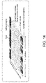
- FIG. 14 is a block diagram of a UCI mapping in LTE, where the x-axis shows Discrete Fourier Transform Spreading Orthogonal Frequency Division Multiplexing (DFTS-OFDM) symbols while the z-axis shows the time within a DFTS-OFDM symbol.
- DFTS-OFDM Discrete Fourier Transform Spreading Orthogonal Frequency Division Multiplexing
- ACK/Negative ACK is mapped to Discrete Fourier Transform Spreading Orthogonal Frequency Division Multiplexing (DFTS-OFDM) symbols closest to DeModulation Reference Signal (DM-RS), Rank Indicator (RI) is mapped to a next consecutive symbol.
- DFTS-OFDM Discrete Fourier Transform Spreading Orthogonal Frequency Division Multiplexing
- RI Rank Indicator
- PMI Precoder Matrix Index
- CQI Channel Quality Information
- CSI Part 1 Channel State Information (CSI) in NR is split into two parts, CSI Part 1 and CSI Part2 which are separately encoded.
- CSI Part 1 has a fixed (determined via Radio Resource Control (RRC) configuration) size and contains the length of CSI Part 2, i.e., Part 1 must be decoded in order to determine the length of Part 2.
- RRC Radio Resource Control
- PUSCH is rate matched around ACK/NACK ("AN") for more than 2 AN bits and punctured for 1 or 2 AN bits.
- AN is mapped, followed by CSI Part 1, then followed by CSI Part 2.
- CSI Part 1 For punctured AN, a certain amount of resources (resource elements) are reserved.
- CSI Part 1 is not mapped on the reserved resources, and CSI Part 1 mapping depends on the amount of reserved resources.
- FIG. 15 is block diagram of punctured acknowledgement/negative acknowledgement.
- CSI part 2 can be mapped on the reserved resources and also on resources after CSI part 1.
- Data (UL-SCH) is mapped on remaining reserved resources and other remaining resources.
- AN is transmitted on the reserved resources, i.e., AN punctures PUSCH and CSI Part 2.
- Some embodiments advantageously provide methods, systems, and apparatuses for helping avoid data loss on the PUSCH due to periodic CSI.
- a method implemented in a wireless device includes receiving a Downlink Control Information (DCI) message for scheduling transmission on a Physical Uplink Shared Channel (PUSCH).
- DCI Downlink Control Information
- PUSCH Physical Uplink Shared Channel
- the DCI message does not contain an indication of how many resources to reserve for Hybrid Automatic Repeat Request (HARQ) bits.
- HARQ Hybrid Automatic Repeat Request
- the method further includes reserving resources on the scheduled PUSCH for 2 HARQ bits.
- a method implemented in a network node includes scheduling the wireless device on a Physical Uplink Shared Channel (PUSCH) using a Downlink Control Information (DCI) message.
- the DCI message does not contain an indication of how many resources to reserve for Hybrid Automatic Repeat Request (HARQ) bits.
- the method further includes transmitting the DCI message to the wireless device.
- PUSCH Physical Uplink Shared Channel
- HARQ Hybrid Automatic Repeat Request
- a wireless device configured to communicate with a network node.
- the wireless device includes a radio interface and a processing circuitry.
- the processing circuit is configured to determine a scheduling of a Physical Uplink Shared Channel (PUSCH) based on a DCI message.
- the DCI message does not contain an indication of how many resources to reserve for Hybrid Automatic Repeat Request (HARQ) bits.
- the processing circuitry is further configured to reserve resources on the scheduled PUSCH for 2 HARQ bits.
- PUSCH Physical Uplink Shared Channel
- a network node configured to communicate with a wireless device.
- the network node comprising a radio interface and comprising processing circuitry.
- the processing circuit is configured to schedule the wireless device on a Physical Uplink Shared Channel (PUSCH) using a Downlink Control Information (DCI) message.
- the DCI message not containing an indication of how many resources to reserve for Hybrid Automatic Repeat Request (HARQ) bits.
- the network node is further configured to transmit the DCI message to the wireless device.
- PUSCH Physical Uplink Shared Channel
- DCI Downlink Control Information
- HARQ Hybrid Automatic Repeat Request
- the disclosure provides for one or more embodiments for avoiding data loss on the PUSCH due to periodic CSI and missed DL assignments on PUSCH that have been scheduled by fallback DCI.
- the CSI is not multiplexed (i.e., drop) on PUSCH if the PUSCH is scheduled by a fallback DCI, i.e., DCI format 0_0. Therefore, the disclosure advantageously helps prevent data loss on PUSCH.
- the number of ACK/NACK bits O ACK follows from the Downlink Assignment Index (DAI) in the UL grant.
- DAI Downlink Assignment Index
- One option is to multiply the obtained amount of resources (the left side of argument/equation in the min() function) by a factor larger than 1 to simplify Discontinuous Transmission (DTX) detection at gNB.
- the fallback Downlink Control Information (DCI)
- no UL DAI is included.
- O ACK can be derived from the detected number of DL assignments. If the wireless device misses a DL assignment, the wireless device will determine a wrong number of O ACK .
- the fallback DCI is likely to be used for small ACK/NACK payloads and up to 2 bit ACK/NACK is punctured, which may provide robustness towards missed DL assignments. For more than 2 bit ACK/NACK is rate matched and a wrong O ACK that results in wrong rate matching and lost PUSCH transmissions. Given that fallback DCI is mainly used with small ACK/NACK payloads (puncturing), this issue may not be so severe.
- the number of reserved resources is determined. If the wireless device uses a different O ACK than the network node, e.g., gNB, the number of reserved resources is different. Since CSI part 1 (CSI1) is not to be mapped to reserved resources, gNB and UE assume different CSI1 mapping resulting in lost CSI1. Further, since PUSCH is rate matched around CSI1, even PUSCH is lost.
- CSI1 CSI part 1
- the disclosure solves at least one of the problems with existing systems by providing for one or more embodiments for avoiding data loss on the PUSCH due to periodic CSI and missed DL assignments on PUSCH that have been scheduled by fallback DCI.
- the CSI is not multiplexed (i.e., drop) on PUSCH if the PUSCH is scheduled by a fallback DCI, i.e., DCI format 0_0. Therefore, the disclosure advantageously helps prevent data loss on PUSCH.
- relational terms such as “first” and “second,” “top” and “bottom,” and the like, may be used solely to distinguish one entity or element from another entity or element without necessarily requiring or implying any physical or logical relationship or order between such entities or elements.
- the terminology used herein is for the purpose of describing particular embodiments only and is not intended to be limiting of the concepts described herein.
- the singular forms “a”, “an” and “the” are intended to include the plural forms as well, unless the context clearly indicates otherwise.
- the joining term, "in communication with” and the like may be used to indicate electrical or data communication, which may be accomplished by physical contact, induction, electromagnetic radiation, radio signaling, infrared signaling or optical signaling, for example.
- electrical or data communication may be accomplished by physical contact, induction, electromagnetic radiation, radio signaling, infrared signaling or optical signaling, for example.
- Coupled may be used herein to indicate a connection, although not necessarily directly, and may include wired and/or wireless connections.
- network node can be any kind of network node comprised in a radio network which may further comprise any of base station (BS), radio base station, base transceiver station (BTS), base station controller (BSC), radio network controller (RNC), g Node B (gNB), evolved Node B (eNB or eNodeB), Node B, multi-standard radio (MSR) radio node such as MSR BS, multi-cell/multicast coordination entity (MCE), relay node, donor node controlling relay, radio access point (AP), transmission points, transmission nodes, Remote Radio Unit (RRU) Remote Radio Head (RRH), a core network node (e.g., mobile management entity (MME), self-organizing network (SON) node, a coordinating node, positioning node, MDT node, etc.), an external node (e.g., 3rd party node, a node external to the current network), nodes in distributed antenna system (DAS), a spectrum access system (SAS) no
- BS base station
- wireless device or a user equipment (UE) are used interchangeably.
- the WD herein can be any type of wireless device capable of communicating with a network node or another WD over radio signals, such as wireless device (WD).
- the WD may also be a radio communication device, target device, device to device (D2D) WD, machine type WD or WD capable of machine to machine communication (M2M), low-cost and/or low-complexity WD, a sensor equipped with WD, Tablet, mobile terminals, smart phone, laptop embedded equipped (LEE), laptop mounted equipment (LME), USB dongles, Customer Premises Equipment (CPE), an Internet of Things (IoT) device, or a Narrowband IoT (NB-IOT) device etc.
- D2D device to device
- M2M machine to machine communication
- M2M machine to machine communication
- Tablet mobile terminals
- smart phone laptop embedded equipped (LEE), laptop mounted equipment (LME), USB dongles
- CPE Customer Premises Equipment
- IoT Internet of Things
- NB-IOT Narrowband IoT
- radio network node can be any kind of a radio network node which may comprise any of base station, radio base station, base transceiver station, base station controller, network controller, RNC, evolved Node B (eNB), Node B, gNB, Multi-cell/multicast Coordination Entity (MCE), relay node, access point, radio access point, Remote Radio Unit (RRU) Remote Radio Head (RRH).
- RNC evolved Node B
- MCE Multi-cell/multicast Coordination Entity
- RRU Remote Radio Unit
- RRH Remote Radio Head
- WCDMA Wide Band Code Division Multiple Access
- WiMax Worldwide Interoperability for Microwave Access
- UMB Ultra Mobile Broadband
- GSM Global System for Mobile Communications
- functions described herein as being performed by a wireless device or a network node may be distributed over a plurality of wireless devices and/or network nodes.
- the functions of the network node and wireless device described herein are not limited to performance by a single physical device and, in fact, can be distributed among several physical devices.
- Embodiments provide for avoiding data loss on the PUSCH due to periodic CSI and missed DL assignments on PUSCH that have been scheduled by fallback DCI.
- the CSI is not multiplexed (i.e., drop) on PUSCH if the PUSCH is scheduled by a fallback DCI, i.e., DCI format 0_0. Therefore, the disclosure advantageously helps prevent data loss on PUSCH.
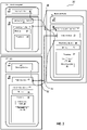
- FIG. 1 a schematic diagram of a communication system, according to an embodiment, including a communication system 10, such as a 3GPP-type cellular network, which comprises an access network 12, such as a radio access network, and a core network 14.
- the access network 12 comprises a plurality of network nodes 16a, 16b, 16c (referred to collectively as network nodes 16), such as NBs, eNBs, gNBs or other types of wireless access points, each defining a corresponding coverage area 18a, 18b, 18c (referred to collectively as coverage areas 18).
- Each network node 16a, 16b, 16c is connectable to the core network 14 over a wired or wireless connection 20.
- a first wireless device (WD) 22a located in coverage area 18a is configured to wirelessly connect to, or be paged by, the corresponding network node 16c.
- a second WD 22b in coverage area 18b is wirelessly connectable to the corresponding network node 16a. While a plurality of WDs 22a, 22b (collectively referred to as wireless devices 22) are illustrated in this example, the disclosed embodiments are equally applicable to a situation where a sole WD is in the coverage area or where a sole WD is connecting to the corresponding network node 16. Note that although only two WDs 22 and three network nodes 16 are shown for convenience, the communication system may include many more WDs 22 and network nodes 16.
- the communication system 10 may itself be connected to a host computer 24, which may be embodied in the hardware and/or software of a standalone server, a cloud-implemented server, a distributed server or as processing resources in a server farm.
- the host computer 24 may be under the ownership or control of a service provider, or may be operated by the service provider or on behalf of the service provider.
- the connections 26, 28 between the communication system 10 and the host computer 24 may extend directly from the core network 14 to the host computer 24 or may extend via an optional intermediate network 30.
- the intermediate network 30 may be one of, or a combination of more than one of, a public, private or hosted network.
- the intermediate network 30, if any, may be a backbone network or the Internet. In some embodiments, the intermediate network 30 may comprise two or more sub-networks (not shown).
- the communication system of FIG. 1 as a whole enables connectivity between one of the connected WDs 22a, 22b and the host computer 24.
- the connectivity may be described as an over-the-top (OTT) connection.
- the host computer 24 and the connected WDs 22a, 22b are configured to communicate data and/or signaling via the OTT connection, using the access network 12, the core network 14, any intermediate network 30 and possible further infrastructure (not shown) as intermediaries.
- the OTT connection may be transparent in the sense that at least some of the participating communication devices through which the OTT connection passes are unaware of routing of uplink and downlink communications.
- a network node 16 may not or need not be informed about the past routing of an incoming downlink communication with data originating from a host computer 24 to be forwarded (e.g., handed over) to a connected WD 22a. Similarly, the network node 16 need not be aware of the future routing of an outgoing uplink communication originating from the WD 22 towards the host computer 24.
- a network node 16 is configured to include a determination unit 32 which is configured to determine to schedule the wireless device on a Physical Uplink Shared Channel (PUSCH) using a Downlink Control Information (DCI) message, the DCI message not containing an indication of how many resources to reserve for Hybrid Automatic Repeat Request (HARQ) bits, and transmit the DCI message to the wireless device.
- a determination unit 32 which is configured to determine to schedule the wireless device on a Physical Uplink Shared Channel (PUSCH) using a Downlink Control Information (DCI) message, the DCI message not containing an indication of how many resources to reserve for Hybrid Automatic Repeat Request (HARQ) bits, and transmit the DCI message to the wireless device.
- DCI Downlink Control Information
- the network node 16 may be configured to includes a reception unit 76 which is configured to receive a transmission on the Physical Uplink Shared Channel (PUSCH), the transmission being based on a Downlink Control Information (DCI) message that does not contain an indication of how many resources to reserve for Hybrid Automatic Repeat Request (HARQ) bits.
- DCI Downlink Control Information
- a wireless device 22 is configured to include a determining unit 34 which is configured to receive a Downlink Control Information (DCI) message for scheduling transmission on a Physical Uplink Shared Channel (PUSCH), the DCI message not containing an indication of how many resources to reserve for Hybrid Automatic Repeat Request (HARQ) bits, and determine to transmit on the scheduled PUSCH based on the DCI message.
- DCI Downlink Control Information
- PUSCH Physical Uplink Shared Channel
- HARQ Hybrid Automatic Repeat Request
- a wireless device 22 is configured to include a transmitting unit 94 which is configured to determine to transmit on a scheduled Physical Uplink Shared Channel (PUSCH) based on a DCI message, the DCI message not containing an indication of how many resources to reserve for Hybrid Automatic Repeat Request (HARQ) bits, and transmit on the scheduled PUSCH based on the determination.
- PUSCH Physical Uplink Shared Channel
- HARQ Hybrid Automatic Repeat Request
- a host computer 24 comprises hardware (HW) 38 including a communication interface 40 configured to set up and maintain a wired or wireless connection with an interface of a different communication device of the communication system 10.
- the host computer 24 further comprises processing circuitry 42, which may have storage and/or processing capabilities.
- the processing circuitry 42 may include a processor 44 and memory 46.
- the processing circuitry 42 may comprise integrated circuitry for processing and/or control, e.g., one or more processors and/or processor cores and/or FPGAs (Field Programmable Gate Array) and/or ASICs (Application Specific Integrated Circuitry) adapted to execute instructions.
- the processor 44 may be configured to access (e.g., write to and/or read from) memory 46, which may comprise any kind of volatile and/or nonvolatile memory, e.g., cache and/or buffer memory and/or RAM (Random Access Memory) and/or ROM (Read-Only Memory) and/or optical memory and/or EPROM (Erasable Programmable Read-Only Memory).
- Processing circuitry 42 may be configured to control any of the methods and/or processes described herein and/or to cause such methods, and/or processes to be performed, e.g., by host computer 24.
- Processor 44 corresponds to one or more processors 44 for performing host computer 24 functions described herein.
- the host computer 24 includes memory 46 that is configured to store data, programmatic software code and/or other information described herein.
- the software 48 and/or the host application 50 may include instructions that, when executed by the processor 44 and/or processing circuitry 42, causes the processor 44 and/or processing circuitry 42 to perform the processes described herein with respect to host computer 24.
- the instructions may be software associated with the host computer 24.
- the software 48 may be executable by the processing circuitry 42.
- the software 48 includes a host application 50.
- the host application 50 may be operable to provide a service to a remote user, such as a WD 22 connecting via an OTT connection 52 terminating at the WD 22 and the host computer 24.
- the host application 50 may provide user data which is transmitted using the OTT connection 52.
- the "user data" may be data and information described herein as implementing the described functionality.
- the host computer 24 may be configured for providing control and functionality to a service provider and may be operated by the service provider or on behalf of the service provider.
- the processing circuitry 42 of the host computer 24 may enable the host computer 24 to observe, monitor, control, transmit to and/or receive from the network node 16 and/or the wireless device 22.
- the communication system 10 further includes a network node 16 provided in a communication system 10 and comprising hardware 58 enabling it to communicate with the host computer 24 and with the WD 22.
- the hardware 58 may include a communication interface 60 for setting up and maintaining a wired or wireless connection with an interface of a different communication device of the communication system 10, as well as a radio interface 62 for setting up and maintaining at least a wireless connection 64 with a WD 22 located in a coverage area 18 served by the network node 16.
- the radio interface 62 may be formed as or may include, for example, one or more RF transmitters, one or more RF receivers, and/or one or more RF transceivers.
- the communication interface 60 may be configured to facilitate a connection 66 to the host computer 24.
- the connection 66 may be direct or it may pass through a core network 14 of the communication system 10 and/or through one or more intermediate networks 30 outside the communication system 10.
- the hardware 58 of the network node 16 further includes processing circuitry 68.
- the processing circuitry 68 may include a processor 70 and a memory 72.
- the processing circuitry 68 may comprise integrated circuitry for processing and/or control, e.g., one or more processors and/or processor cores and/or FPGAs (Field Programmable Gate Array) and/or ASICs (Application Specific Integrated Circuitry) adapted to execute instructions.
- FPGAs Field Programmable Gate Array
- ASICs Application Specific Integrated Circuitry
- the processor 70 may be configured to access (e.g., write to and/or read from) the memory 72, which may comprise any kind of volatile and/or nonvolatile memory, e.g., cache and/or buffer memory and/or RAM (Random Access Memory) and/or ROM (Read-Only Memory) and/or optical memory and/or EPROM (Erasable Programmable Read-Only Memory).
- volatile and/or nonvolatile memory e.g., cache and/or buffer memory and/or RAM (Random Access Memory) and/or ROM (Read-Only Memory) and/or optical memory and/or EPROM (Erasable Programmable Read-Only Memory).
- the network node 16 further has software 74 stored internally in, for example, memory 72, or stored in external memory (e.g., database) accessible by the network node 16 via an external connection.
- the software 74 may be executable by the processing circuitry 68.
- the processing circuitry 68 may be configured to control any of the methods and/or processes described herein and/or to cause such methods, and/or processes to be performed, e.g., by network node 16.
- Processor 70 corresponds to one or more processors 70 for performing network node 16 functions described herein.
- the memory 72 is configured to store data, programmatic software code and/or other information described herein.
- the software 74 may include instructions that, when executed by the processor 70 and/or processing circuitry 68, causes the processor 70 and/or processing circuitry 68 to perform the processes described herein with respect to network node 16.
- processing circuitry 68 of the network node 16 may include determination unit 32 configured to determine to schedule the wireless device on a Physical Uplink Shared Channel (PUSCH) using a Downlink Control Information (DCI) message, the DCI message not containing an indication of how many resources to reserve for Hybrid Automatic Repeat Request (HARQ) bits (), and transmit the DCI message to the wireless device, as described herein.
- DCI Downlink Control Information
- the processing circuitry 68 may also include reception unit 76 configured to receive a transmission on the Physical Uplink Shared Channel (PUSCH), the transmission being based on a Downlink Control Information (DCI) message that does not contain an indication of how many resources to reserve for Hybrid Automatic Repeat Request (HARQ) bits, as described herein.
- DCI Downlink Control Information
- the communication system 10 further includes the WD 22 already referred to.
- the WD 22 may have hardware 80 that may include a radio interface 82 configured to set up and maintain a wireless connection 64 with a network node 16 serving a coverage area 18 in which the WD 22 is currently located.
- the radio interface 82 may be formed as or may include, for example, one or more RF transmitters, one or more RF receivers, and/or one or more RF transceivers.
- the hardware 80 of the WD 22 further includes processing circuitry 84.
- the processing circuitry 84 may include a processor 86 and memory 88.
- the processing circuitry 84 may comprise integrated circuitry for processing and/or control, e.g., one or more processors and/or processor cores and/or FPGAs (Field Programmable Gate Array) and/or ASICs (Application Specific Integrated Circuitry) adapted to execute instructions.
- FPGAs Field Programmable Gate Array
- ASICs Application Specific Integrated Circuitry
- the processor 86 may be configured to access (e.g., write to and/or read from) memory 88, which may comprise any kind of volatile and/or nonvolatile memory, e.g., cache and/or buffer memory and/or RAM (Random Access Memory) and/or ROM (Read-Only Memory) and/or optical memory and/or EPROM (Erasable Programmable Read-Only Memory).
- memory 88 may comprise any kind of volatile and/or nonvolatile memory, e.g., cache and/or buffer memory and/or RAM (Random Access Memory) and/or ROM (Read-Only Memory) and/or optical memory and/or EPROM (Erasable Programmable Read-Only Memory).
- the WD 22 may further comprise software 90, which is stored in, for example, memory 88 at the WD 22, or stored in external memory (e.g., database) accessible by the WD 22.
- the software 90 may be executable by the processing circuitry 84.
- the software 90 may include a client application 92.
- the client application 92 may be operable to provide a service to a human or non-human user via the WD 22, with the support of the host computer 24.
- an executing host application 50 may communicate with the executing client application 92 via the OTT connection 52 terminating at the WD 22 and the host computer 24.
- the client application 92 may receive request data from the host application 50 and provide user data in response to the request data.
- the OTT connection 52 may transfer both the request data and the user data.
- the client application 92 may interact with the user to generate the user data that it provides.
- the processing circuitry 84 may be configured to control any of the methods and/or processes described herein and/or to cause such methods, and/or processes to be performed, e.g., by WD 22.
- the processor 86 corresponds to one or more processors 86 for performing WD 22 functions described herein.
- the WD 22 includes memory 88 that is configured to store data, programmatic software code and/or other information described herein.
- the software 90 and/or the client application 92 may include instructions that, when executed by the processor 86 and/or processing circuitry 84, causes the processor 86 and/or processing circuitry 84 to perform the processes described herein with respect to WD 22.
- the processing circuitry 84 of the wireless device 22 may include a determining unit 34 configured to receive a Downlink Control Information (DCI) message for scheduling transmission on a Physical Uplink Shared Channel (PUSCH), the DCI message not containing an indication of how many resources to reserve for Hybrid Automatic Repeat Request (HARQ) bits, and determine to transmit on the scheduled PUSCH based on the DCI message.
- DCI Downlink Control Information
- PUSCH Physical Uplink Shared Channel
- HARQ Hybrid Automatic Repeat Request
- the processing circuitry 84 may also include transmitting unit 94 configured to determine to transmit on a scheduled Physical Uplink Shared Channel (PUSCH) based on a DCI message, the DCI message not containing an indication of how many resources to reserve for Hybrid Automatic Repeat Request (HARQ) bits, and transmit on the scheduled PUSCH based on the determination.
- transmitting unit 94 configured to determine to transmit on a scheduled Physical Uplink Shared Channel (PUSCH) based on a DCI message, the DCI message not containing an indication of how many resources to reserve for Hybrid Automatic Repeat Request (HARQ) bits, and transmit on the scheduled PUSCH based on the determination.
- PUSCH Physical Uplink Shared Channel
- the inner workings of the network node 16, WD 22, and host computer 24 may be as shown in FIG. 2 and independently, the surrounding network topology may be that of FIG. 1 .
- the OTT connection 52 has been drawn abstractly to illustrate the communication between the host computer 24 and the wireless device 22 via the network node 16, without explicit reference to any intermediary devices and the precise routing of messages via these devices.
- Network infrastructure may determine the routing, which it may be configured to hide from the WD 22 or from the service provider operating the host computer 24, or both. While the OTT connection 52 is active, the network infrastructure may further take decisions by which it dynamically changes the routing (e.g., on the basis of load balancing consideration or reconfiguration of the network).
- the wireless connection 64 between the WD 22 and the network node 16 is in accordance with the teachings of the embodiments described throughout this disclosure.
- One or more of the various embodiments improve the performance of OTT services provided to the WD 22 using the OTT connection 52, in which the wireless connection 64 may form the last segment. More precisely, the teachings of some of these embodiments may improve the data rate, latency, and/or power consumption and thereby provide benefits such as reduced user waiting time, relaxed restriction on file size, better responsiveness, extended battery lifetime, etc.
- a measurement procedure may be provided for the purpose of monitoring data rate, latency and other factors on which the one or more embodiments improve.
- the measurement procedure and/or the network functionality for reconfiguring the OTT connection 52 may be implemented in the software 48 of the host computer 24 or in the software 90 of the WD 22, or both.
- sensors (not shown) may be deployed in or in association with communication devices through which the OTT connection 52 passes; the sensors may participate in the measurement procedure by supplying values of the monitored quantities exemplified above, or supplying values of other physical quantities from which software 48, 90 may compute or estimate the monitored quantities.
- the reconfiguring of the OTT connection 52 may include message format, retransmission settings, preferred routing etc.; the reconfiguring need not affect the network node 16, and it may be unknown or imperceptible to the network node 16. Some such procedures and functionalities may be known and practiced in the art.
- measurements may involve proprietary WD signaling facilitating the host computer's 24 measurements of throughput, propagation times, latency and the like.
- the measurements may be implemented in that the software 48, 90 causes messages to be transmitted, in particular empty or 'dummy' messages, using the OTT connection 52 while it monitors propagation times, errors etc.
- FIGS. 1 and 2 show various "units" such as determination unit 32, determining unit 34, reception unit 76 and transmitting unit 94 as being within a respective processor, it is contemplated that these units may be implemented such that a portion of the unit is stored in a corresponding memory within the processing circuitry. In other words, the units may be implemented in hardware or in a combination of hardware and software within the processing circuitry.
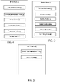
- FIG. 3 is a block diagram of an alternative host computer 24, which may be implemented at least in part by software modules containing software executable by a processor to perform the functions described herein.
- the host computer 24 include a communication interface module 41 configured to set up and maintain a wired or wireless connection with an interface of a different communication device of the communication system 10.
- the memory module 47 is configured to store data, programmatic software code and/or other information described herein.
- FIG. 4 is a block diagram of an alternative network node 16, which may be implemented at least in part by software modules containing software executable by a processor to perform the functions described herein.
- the network node 16 includes a radio interface module 63 configured for setting up and maintaining at least a wireless connection 64 with a WD 22 located in a coverage area 18 served by the network node 16.
- the network node 16 also includes a communication interface module 61 configured for setting up and maintaining a wired or wireless connection with an interface of a different communication device of the communication system 10.
- the communication interface module 61 may also be configured to facilitate a connection 66 to the host computer 24.
- the memory module 73 that is configured to store data, programmatic software code and/or other information described herein.
- the determination module 33 is configured to determine to schedule the wireless device on a Physical Uplink Shared Channel (PUSCH) using a Downlink Control Information (DCI) message, the DCI message not containing an indication of how many resources to reserve for Hybrid Automatic Repeat Request (HARQ) bits.
- the transmission module 77 is configured to transmits the DCI message to the wireless device.
- the reception module 79 is configured to receive a transmission on the Physical Uplink Shared Channel (PUSCH), the transmission being based on a Downlink Control Information (DCI) message that does not contain an indication of how many resources to reserve for Hybrid Automatic Repeat Request (HARQ) bits.
- DCI Downlink Control Information
- FIG. 5 is a block diagram of an alternative wireless device 22, which may be implemented at least in part by software modules containing software executable by a processor to perform the functions described herein.
- the WD 22 includes a radio interface module 83 configured to set up and maintain a wireless connection 64 with a network node 16 serving a coverage area 18 in which the WD 22 is currently located.
- the memory module 89 is configured to store data, programmatic software code and/or other information described herein.
- the receiving module 35 is configured to receive a Downlink Control Information (DCI) message for scheduling transmission on a Physical Uplink Shared Channel (PUSCH), the DCI message not containing an indication of how many resources to reserve for Hybrid Automatic Repeat Request (HARQ) bits.
- DCI Downlink Control Information
- PUSCH Physical Uplink Shared Channel
- the determining module 95 is configured to determine to transmit on the scheduled PUSCH based on the DCI message.
- the determining module 97 is configured to determine to transmit on a scheduled Physical Uplink Shared Channel (PUSCH) based on a DCI message, the DCI message not containing an indication of how many resources to reserve for Hybrid Automatic Repeat Request (HARQ) bits.
- the transmitting module 98 is configured to transmit on the scheduled PUSCH based on the determination.
- FIG. 6 is a flowchart illustrating an exemplary method implemented in a communication system, such as, for example, the communication system of FIGS. 1 and 2 , in accordance with one embodiment.
- the communication system may include a host computer 24, a network node 16 and a WD 22, which may be those described with reference to FIG. 2 .
- the host computer 24 provides user data (block S100).
- the host computer 24 provides the user data by executing a host application, such as, for example, the host application 74 (block S102).
- a second step the host computer 24 initiates a transmission carrying the user data to the WD 22 (block S104).
- the network node 16 transmits to the WD 22 the user data which was carried in the transmission that the host computer 22 initiated, in accordance with the teachings of the embodiments described throughout this disclosure (block S106).
- the WD 22 executes a client application, such as, for example, the client application 114, associated with the host application 74 executed by the host computer 24 (block S108).
- FIG. 7 is a flowchart illustrating an exemplary method implemented in a communication system, such as, for example, the communication system of FIG. 1 , in accordance with one embodiment.
- the communication system may include a host computer 24, a network node 16 and a WD 22, which may be those described with reference to FIGS. 1 and 2 .
- the host computer 24 provides user data (block S110).
- the host computer 24 provides the user data by executing a host application, such as, for example, the host application 74.
- the host computer 24 initiates a transmission carrying the user data to the WD 22 (block S112).
- the transmission may pass via the network node 16, in accordance with the teachings of the embodiments described throughout this disclosure.
- the WD 22 receives the user data carried in the transmission (block S114).
- FIG. 8 is a flowchart illustrating an exemplary method implemented in a communication system, such as, for example, the communication system of FIG. 1 , in accordance with one embodiment.
- the communication system may include a host computer 24, a network node 16 and a WD 22, which may be those described with reference to FIGS. 1 and 2 .
- the WD 22 receives input data provided by the host computer 24 (block S116).
- the WD 22 executes the client application 114, which provides the user data in reaction to the received input data provided by the host computer 24 (block S118).
- the WD 22 provides user data (block S120).
- the WD provides the user data by executing a client application, such as, for example, client application 114 (block S122).
- client application 114 may further consider user input received from the user.
- the WD 22 may initiate, in an optional third substep, transmission of the user data to the host computer 24 (block S124).
- the host computer 24 receives the user data transmitted from the WD 22, in accordance with the teachings of the embodiments described throughout this disclosure (block S126).
- FIG. 9 is a flowchart illustrating an exemplary method implemented in a communication system, such as, for example, the communication system of FIG. 1 , in accordance with one embodiment.
- the communication system may include a host computer 24, a network node 16 and a WD 22, which may be those described with reference to FIGS. 1 and 2 .
- the network node 16 receives user data from the WD 22 (block S128).
- the network node 16 initiates transmission of the received user data to the host computer 24 (block S130).
- the host computer 24 receives the user data carried in the transmission initiated by the network node 16 (block S132).
- FIG. 10 is a flowchart of an exemplary process in a network node 16 for scheduling PUSCH using a DCI message according to some embodiments of the present disclosure.
- Processing circuitry 68 is configured to schedule the wireless device 22 on a Physical Uplink Shared Channel (PUSCH) using a Downlink Control Information (DCI) message in which the DCI message not containing an indication of how many resources to reserve for Hybrid Automatic Repeat Request (HARQ) bits (block S134).
- DCI Downlink Control Information
- Processing circuitry 68 is further configured to, optionally, transmit the DCI message to the wireless device 22 (block S136).
- the DCI message not containing the indication of how many resources to reserve for HARQ bits corresponds to the DCI message not indicating an uplink (UL) downlink assignment index (DAI).
- the DCI message is of DCI format 0_0.
- FIG. 11 is a flowchart of an exemplary process in a wireless device 22 using DCI message for PUSCH according to some embodiments of the present disclosure.
- Processing circuitry 84 is configured to receive a Downlink Control Information (DCI) message for scheduling transmission on a Physical Uplink Shared Channel (PUSCH) in which the DCI message not containing an indication of how many resources to reserve for Hybrid Automatic Repeat Request (HARQ) bits (block S 138).
- Processing circuitry 84 is further configured to reserving resources on the scheduled PUSCH for 2 HARQ bits (block S139).
- Processing circuitry 84 is further configured to, optionally, transmit on the scheduled PUSCH based on the DCI message (block S140).
- the DCI message not containing the indication of how many resources to reserve for HARQ bits corresponds to the DCI message not indicating an uplink (UL) downlink assignment index (DAI).
- the DCI message is of DCI format 0_0.
- the transmission on the scheduled PUSCH is configured to not include Channel State Information (CSI) in the transmission.
- the transmission includes reserving sources on the PUSCH for at least one Hybrid Automatic Repeat Request (HARQ) bit if the WD has Channel State Information (CSI) to report.
- processing circuitry 84 is configured to reserve resources on the scheduled PUSCH for 1 Hybrid Automatic Repeat Request (HARQ) bit or 2 HARQ bits.
- HARQ Hybrid Automatic Repeat Request
- the transmission on the scheduled PUSCH includes mapping a first part of Channel State Information (CSI) to predefined portion of the scheduled PUSCH.
- CSI Channel State Information
- the predefined portion of the scheduled PUSCH corresponds to an end portion of the scheduled PUSCH.
- FIG. 12 is a flowchart of an exemplary process in a network node 16 according to some embodiments of the present disclosure.
- Processing circuitry 68 is configured to receive a transmission on the Physical Uplink Shared Channel (PUSCH) in which the transmission being based on a Downlink Control Information (DCI) message that does not contain an indication of how many resources to reserve for Hybrid Automatic Repeat Request (HARQ) bits (block S142).
- DCI Downlink Control Information
- HARQ Hybrid Automatic Repeat Request
- the DCI message not containing the indication of how many resources to reserve for HARQ bits corresponds to the DCI message not indicating an uplink (UL) downlink assignment index (DAI).
- the DCI message is of DCI format 0_0.
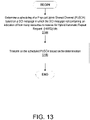
- FIG. 13 is a flowchart of an exemplary process in a wireless device 22 according to some embodiments of the present disclosure.
- Processing circuitry 84 is configured to determine a scheduling of a Physical Uplink Shared Channel (PUSCH) based on a DCI message in which the DCI message does not contain an indication of how many resources to reserve for Hybrid Automatic Repeat Request (HARQ) bits (block S144).
- Processing circuitry 84 is further configured to, optionally, transmit on the scheduled PUSCH based on the determination (block S146).
- PUSCH Physical Uplink Shared Channel
- HARQ Hybrid Automatic Repeat Request
- the DCI message not containing the indication of how many resources to reserve for HARQ bits corresponds to the DCI message not indicating an uplink (UL) downlink assignment index (DAI).
- the DCI message is of DCI format 0_0.
- the transmission on the scheduled PUSCH does not include Channel State Information (CSI) in the transmission, i.e., is configured not to includes CSI.
- the transmission on the scheduled PUSCH includes reserving sources on the PUSCH for at least one Hybrid Automatic Repeat Request (HARQ) bit if the WD has Channel State Information (CSI) to report.
- processing circuitry 84 is configured to reserve resources on the scheduled PUSCH for 1 Hybrid Automatic Repeat Request (HARQ) bit or 2 HARQ bits.
- HARQ Hybrid Automatic Repeat Request
- the transmission on the scheduled PUSCH includes mapping a first part of Channel State Information (CSI) to predefined portion of the scheduled PUSCH.
- CSI Channel State Information
- the predefined portion of the scheduled PUSCH corresponds to an end portion of the scheduled PUSCH.
- Embodiments provide avoiding data loss on the PUSCH due to periodic CSI and missed DL assignments on PUSCH that have been scheduled by fallback DCI.
- the CSI is not multiplexed (i.e., drop) on PUSCH if the PUSCH is scheduled by a fallback DCI, i.e., DCI format 0_0. Therefore, the disclosure advantageously helps prevent data loss on PUSCH. Embodiments are further described below.
- the WD 22 may always drop a (periodic or semi-persistent) CSI/CSI report if the CSI is supposed to be multiplexed on a PUSCH transmission when the PUSCH transmission was scheduled by a fallback DCI message.
- a fallback DCI message may include, for example, a DCI message of DCI format 0_0.
- a fallback DCI message refers to a DCI message that does not contain any indication about how many resources should be reserved for HARQ-ACK bits.
- such a fallback DCI message corresponds to a DCI message without UL downlink assignment index (DAI) contained in the UL grant.
- DAI downlink assignment index
- the fallback DCI in NR does not include a CSI request field and the only CSI that could be included in a PUSCH scheduled by the fallback DCI is periodic or semi-persistent CSI, which have been configured for transmission on Physical Uplink Control Channel (PUCCH), but where the PUCCH resource collide with a scheduled PUSCH and so the CSI is piggybacked on the PUSCH.
- the fallback DCI contains a CSI request field, the same problem could occur with an aperiodic CSI report.
- the WD 22 does not include a CSI report.
- an assumption is made that the WD 22 reserves resources on PUSCH for either 1 or 2 HARQ-ACK bits (which can be specified or configured) so as to account for the largest/typical possible HARQ-ACK bits, independent from if and how many (1 or 2) HARQ-ACK bits the WD 22 has to transmits.
- this embodiment may apply for the case where the WD 22 is scheduled with a DCI format for PUSCH without DAI field and the WD 22 has CSI to report, e.g., for example DCI format 0_0.
- a different mapping is implemented, either: (1) only when PUSCH is scheduled with a fallback DCI (or DCI without UL DAI)(potentially also conditioned on the number of received DL assignments: if the WD 22 reports more than 2 AN bits PUSCH is rate matched around AN, in this case the current CSI mapping could be assumed) or (2) always (i.e., irrespective of the DCI format scheduling PUSCH), where in (1) or (2), the CSI part1 is mapped at the end (i.e., end portion) of PUSCH. In this embodiment, CSI part 1 would not move around depending on the amount of reserved resources and thus also PUSCH mapping would not change.
- the network node 16 implementation avoids scheduling the WD 22 with PUSCH transmission by a DCI message without a DAI field (i.e., with a fallback DCI) in case the WD 22 has a periodic CSI report occasion and has been scheduled with PDSCH requiring 1 or 2 HARQ-ACK bits to report.
- the network node 16 implementation applies a dual decoding scheme where the network node 16 attempts to decode PUSCH assuming no HARQ-ACK bits are present or HARQ-ACK bit(s) are present. Note that there are two lengths of the HARQ-ACK bits payload, potentially one for 1 bit and one for 2 bits. This embodiment can result in a total of three decoding attempts.
- one or more embodiments of the disclosure advantageously provides for, if PUSCH is scheduled with a fallback DCI (or a DCI that does not contain an UL DAI), CSI to be dropped to avoid lost PUSCH, caused by missed DL detections.
- one or more embodiments of the disclosure solve at least one of the problems with existing systems by providing for one or more embodiments for avoiding data loss on the PUSCH due to periodic CSI and missed DL assignments on PUSCH that have been scheduled by fallback DCI.
- the CSI is not multiplexed (i.e., drop) on PUSCH if the PUSCH is scheduled by a fallback DCI, i.e., DCI format 0_0. Therefore, the disclosure advantageously helps prevent data loss on PUSCH.
- the concepts described herein may be embodied as a method, data processing system, and/or computer program product. Accordingly, the concepts described herein may take the form of an entirely hardware embodiment, an entirely software embodiment or an embodiment combining software and hardware aspects all generally referred to herein as a "circuit" or "module.” Furthermore, the disclosure may take the form of a computer program product on a tangible computer usable storage medium having computer program code embodied in the medium that can be executed by a computer. Any suitable tangible computer readable medium may be utilized including hard disks, CD-ROMs, electronic storage devices, optical storage devices, or magnetic storage devices.
- These computer program instructions may also be stored in a computer readable memory or storage medium that can direct a computer or other programmable data processing apparatus to function in a particular manner, such that the instructions stored in the computer readable memory produce an article of manufacture including instruction means which implement the function/act specified in the flowchart and/or block diagram block or blocks.
- the computer program instructions may also be loaded onto a computer or other programmable data processing apparatus to cause a series of operational steps to be performed on the computer or other programmable apparatus to produce a computer implemented process such that the instructions which execute on the computer or other programmable apparatus provide steps for implementing the functions/acts specified in the flowchart and/or block diagram block or blocks.
- Computer program code for carrying out operations of the concepts described herein may be written in an object oriented programming language such as Java ® or C++.
- the computer program code for carrying out operations of the disclosure may also be written in conventional procedural programming languages, such as the "C" programming language.
- the program code may execute entirely on the user's computer, partly on the user's computer, as a stand-alone software package, partly on the user's computer and partly on a remote computer or entirely on the remote computer.
- the remote computer may be connected to the user's computer through a local area network (LAN) or a wide area network (WAN), or the connection may be made to an external computer (for example, through the Internet using an Internet Service Provider).
- LAN local area network
- WAN wide area network
- Internet Service Provider for example, AT&T, MCI, Sprint, EarthLink, MSN, GTE, etc.
- the attached Appendix provides non-limiting examples of how certain aspects of the proposed solutions could be implemented within the framework of a specific communication standard.
- the attached Appendix provides non-limiting examples of how the proposed solutions could be implemented within the framework of a 3GPP TSG RAN standard.
- the changes described by the Appendix are merely intended to illustrate how certain aspects of the proposed solutions could be implemented in a particular standard.
- the proposed solutions could also be implemented in other suitable manners, both in the 3GPP Specification and in other specifications or standards.
Landscapes
- Engineering & Computer Science (AREA)
- Signal Processing (AREA)
- Computer Networks & Wireless Communication (AREA)
- Mobile Radio Communication Systems (AREA)
Applications Claiming Priority (2)
| Application Number | Priority Date | Filing Date | Title |
|---|---|---|---|
| US201862617128P | 2018-01-12 | 2018-01-12 | |
| EP19151476.9A EP3565157B1 (en) | 2018-01-12 | 2019-01-11 | Physical uplink shared channel with hybrid automatic repeat request acknowledgement |
Related Parent Applications (2)
| Application Number | Title | Priority Date | Filing Date |
|---|---|---|---|
| EP19151476.9A Division EP3565157B1 (en) | 2018-01-12 | 2019-01-11 | Physical uplink shared channel with hybrid automatic repeat request acknowledgement |
| EP19151476.9A Division-Into EP3565157B1 (en) | 2018-01-12 | 2019-01-11 | Physical uplink shared channel with hybrid automatic repeat request acknowledgement |
Publications (1)
| Publication Number | Publication Date |
|---|---|
| EP4002733A1 true EP4002733A1 (en) | 2022-05-25 |
Family
ID=65019430
Family Applications (2)
| Application Number | Title | Priority Date | Filing Date |
|---|---|---|---|
| EP19151476.9A Active EP3565157B1 (en) | 2018-01-12 | 2019-01-11 | Physical uplink shared channel with hybrid automatic repeat request acknowledgement |
| EP21195427.6A Withdrawn EP4002733A1 (en) | 2018-01-12 | 2019-01-11 | Physical uplink shared channel with hybrid automatic repeat request acknowledgement |
Family Applications Before (1)
| Application Number | Title | Priority Date | Filing Date |
|---|---|---|---|
| EP19151476.9A Active EP3565157B1 (en) | 2018-01-12 | 2019-01-11 | Physical uplink shared channel with hybrid automatic repeat request acknowledgement |
Country Status (15)
| Country | Link |
|---|---|
| US (2) | US10587386B2 (es) |
| EP (2) | EP3565157B1 (es) |
| JP (1) | JP2021510962A (es) |
| KR (1) | KR20200093664A (es) |
| CN (1) | CN111587548B (es) |
| AU (1) | AU2019207785A1 (es) |
| BR (1) | BR112020012845A2 (es) |
| CA (1) | CA3088049A1 (es) |
| CL (1) | CL2020001837A1 (es) |
| ES (1) | ES2901158T3 (es) |
| HU (1) | HUE057226T2 (es) |
| MX (1) | MX2020006872A (es) |
| PH (1) | PH12020500578A1 (es) |
| RU (1) | RU2752649C1 (es) |
| WO (1) | WO2019138023A1 (es) |
Families Citing this family (11)
| Publication number | Priority date | Publication date | Assignee | Title |
|---|---|---|---|---|
| CN110226292A (zh) * | 2017-01-24 | 2019-09-10 | 瑞典爱立信有限公司 | 多天线通信系统中的信道状态信息的管理 |
| US10813118B2 (en) * | 2017-07-10 | 2020-10-20 | Lg Electronics Inc. | Method for transmitting and receiving uplink control information and devices supporting the same |
| WO2019144919A1 (en) * | 2018-01-24 | 2019-08-01 | Guangdong Oppo Mobile Telecommunications Corp., Ltd. | Transmission channel assignment apparatus and method for controlling a transmission over a transmission channel |
| JP2020025217A (ja) * | 2018-08-08 | 2020-02-13 | シャープ株式会社 | 端末装置、基地局装置、および、通信方法 |
| CN110831214B (zh) * | 2018-08-10 | 2023-10-13 | 华为技术有限公司 | 通信方法和装置 |
| CN110943805B (zh) * | 2018-09-21 | 2021-06-04 | 电信科学技术研究院有限公司 | 一种harq-ack的传输方法、终端设备及网络设备 |
| CN111342942B (zh) * | 2018-12-19 | 2021-09-21 | 北京紫光展锐通信技术有限公司 | 上行控制信息的上报方法及装置、存储介质、用户终端 |
| CN110536450A (zh) * | 2019-09-03 | 2019-12-03 | 中兴通讯股份有限公司 | 一种数据传输方法、装置、传输接收节点、终端及介质 |
| US11165482B1 (en) * | 2020-08-20 | 2021-11-02 | Nxp Usa, Inc. | Efficient engine and algorithm for control and data multiplexing/demultiplexing in 5G NR devices |
| US20220263603A1 (en) * | 2021-02-16 | 2022-08-18 | Samsung Electronics Co., Ltd. | Multiplexing unicast and multicast control information |
| CN114710244B (zh) * | 2022-03-14 | 2023-06-06 | 四川创智联恒科技有限公司 | 一种nr小区harq反馈的方法、电子设备及存储介质 |
Family Cites Families (27)
| Publication number | Priority date | Publication date | Assignee | Title |
|---|---|---|---|---|
| US8442564B2 (en) * | 2011-01-13 | 2013-05-14 | Motorola Mobility Llc | Inter-modulation distortion reduction in multi-mode wireless communication terminal |
| EP2490362B1 (en) * | 2011-02-15 | 2018-04-04 | LG Electronics Inc. | Method and apparatus for transmitting channel quality control information in wireless access system |
| CN102740465B (zh) * | 2011-04-01 | 2016-03-30 | 华为技术有限公司 | 数据传输方法、装置及系统 |
| KR101565423B1 (ko) * | 2011-07-15 | 2015-11-03 | 엘지전자 주식회사 | 하향링크 신호 수신방법 및 사용자기기와, 하향링크 신호 전송방법 및 기지국 |
| US20140169319A1 (en) * | 2011-07-26 | 2014-06-19 | Lg Electronics Inc. | Method for transmitting uplink signal, user equipment, method for receiving uplink signal, and base station |
| US9337984B2 (en) * | 2011-08-19 | 2016-05-10 | Lg Electronics Inc. | Method for transmitting uplink control information, user equipment, method for receiving uplink control information, and base station |
| EP2761955B1 (en) * | 2011-09-30 | 2017-07-26 | Interdigital Patent Holdings, Inc. | Device communication using a reduced channel bandwidth |
| US9826514B2 (en) * | 2011-11-16 | 2017-11-21 | Qualcomm Incorporated | Downlink control information (DCI) design for low cost devices |
| WO2013105837A1 (ko) * | 2012-01-15 | 2013-07-18 | 엘지전자 주식회사 | 무선 통신 시스템에서 제어 정보 전송 방법 및 장치 |
| US9014064B2 (en) * | 2012-05-11 | 2015-04-21 | Intel Corporation | Scheduling and hybrid automatic repeat request (HARQ) timing indication for an uplink-downlink (UL-DL) reconfiguration |
| WO2014021631A1 (ko) * | 2012-07-31 | 2014-02-06 | 엘지전자 주식회사 | 하향링크 신호 수신 방법 및 사용자기기와, 하향링크 신호 전송 방법 및 기지국 |
| US8923880B2 (en) * | 2012-09-28 | 2014-12-30 | Intel Corporation | Selective joinder of user equipment with wireless cell |
| US10530549B2 (en) * | 2012-11-28 | 2020-01-07 | Lg Electronics Inc. | Method for receiving or transmitting downlink control signal in wireless communication system, and apparatus therefor |
| WO2014148796A1 (ko) * | 2013-03-19 | 2014-09-25 | 엘지전자 주식회사 | 무선 통신 시스템에서 단말이 신호를 송수신하는 방법 및 이를 위한 장치 |
| EP3011699B1 (en) * | 2013-09-27 | 2017-09-20 | Huawei Technologies Co., Ltd. | Harq feedback using carrier aggregation |
| JP6306204B2 (ja) * | 2014-03-27 | 2018-04-04 | エルジー エレクトロニクス インコーポレイティド | 無線通信システムにおいて下りリンク信号の送受信方法及びそのための装置 |
| KR102518821B1 (ko) * | 2015-01-20 | 2023-04-06 | 엘지전자 주식회사 | 상향링크 제어 정보를 전송하기 위한 방법 및 이를 위한 장치 |
| US9686064B2 (en) * | 2015-01-21 | 2017-06-20 | Intel IP Corporation | Devices and methods for HARQ-ACK feedback scheme on PUSCH in wireless communication systems |
| KR102233137B1 (ko) * | 2015-04-10 | 2021-03-26 | 텔레폰악티에볼라겟엘엠에릭슨(펍) | 다수의 캐리어를 위한 pusch에서의 harq 구현 |
| CN106301670A (zh) * | 2015-05-15 | 2017-01-04 | 中兴通讯股份有限公司 | 上行控制信息的发送方法及装置 |
| EP3226456B1 (en) * | 2016-04-01 | 2020-06-03 | Panasonic Intellectual Property Corporation of America | Asynchronous retransmission protocol |
| SG11201905795VA (en) * | 2017-02-05 | 2019-08-27 | Lg Electronics Inc | Method for terminal transmitting uplink control information in wireless communication system and apparatus supporting same |
| US10813118B2 (en) * | 2017-07-10 | 2020-10-20 | Lg Electronics Inc. | Method for transmitting and receiving uplink control information and devices supporting the same |
| US10812241B2 (en) * | 2017-09-11 | 2020-10-20 | Qualcomm Incorporated | Techniques and apparatuses for HARQ-ACK timeline indication and HARQ-ACK multiplexing and bundling in new radio |
| US10779310B2 (en) * | 2017-11-16 | 2020-09-15 | Qualcomm Incorporated | Uplink control channel resource allocation for new radio (NR) |
| US20190215172A1 (en) * | 2018-01-09 | 2019-07-11 | ACTeq, LLC | Group Communication Enabled Tool Tips |
| US10790955B2 (en) * | 2018-01-11 | 2020-09-29 | Mediatek Inc. | Reservation of HARQ-ACK resources in uplink control information in wireless communications |
-
2019
- 2019-01-11 US US16/245,407 patent/US10587386B2/en active Active
- 2019-01-11 AU AU2019207785A patent/AU2019207785A1/en not_active Abandoned
- 2019-01-11 MX MX2020006872A patent/MX2020006872A/es unknown
- 2019-01-11 WO PCT/EP2019/050606 patent/WO2019138023A1/en active Application Filing
- 2019-01-11 EP EP19151476.9A patent/EP3565157B1/en active Active
- 2019-01-11 JP JP2020537772A patent/JP2021510962A/ja active Pending
- 2019-01-11 EP EP21195427.6A patent/EP4002733A1/en not_active Withdrawn
- 2019-01-11 HU HUE19151476A patent/HUE057226T2/hu unknown
- 2019-01-11 BR BR112020012845-7A patent/BR112020012845A2/pt unknown
- 2019-01-11 RU RU2020126839A patent/RU2752649C1/ru active
- 2019-01-11 KR KR1020207019995A patent/KR20200093664A/ko not_active IP Right Cessation
- 2019-01-11 ES ES19151476T patent/ES2901158T3/es active Active
- 2019-01-11 CN CN201980008154.6A patent/CN111587548B/zh active Active
- 2019-01-11 CA CA3088049A patent/CA3088049A1/en not_active Abandoned
-
2020
- 2020-02-04 US US16/781,677 patent/US20200177351A1/en not_active Abandoned
- 2020-07-02 PH PH12020500578A patent/PH12020500578A1/en unknown
- 2020-07-10 CL CL2020001837A patent/CL2020001837A1/es unknown
Non-Patent Citations (3)
| Title |
|---|
| HUAWEI ET AL: "On UCI multiplexing", vol. RAN WG1, no. Reno, USA; 20171127 - 20171201, 18 November 2017 (2017-11-18), XP051369306, Retrieved from the Internet <URL:http://www.3gpp.org/ftp/tsg%5Fran/WG1%5FRL1/TSGR1%5F91/Docs/> [retrieved on 20171118] * |
| LG ELECTRONICS: "UCI on PUSCH and UL channel multiplexing for NR", vol. RAN WG1, no. Reno, USA; 20171127 - 20171201, 18 November 2017 (2017-11-18), XP051369640, Retrieved from the Internet <URL:http://www.3gpp.org/ftp/tsg%5Fran/WG1%5FRL1/TSGR1%5F91/Docs/> [retrieved on 20171118] * |
| NTT DOCOMO ET AL: "UCI multiplexing", vol. RAN WG1, no. Reno, USA; 20171127 - 20171201, 18 November 2017 (2017-11-18), XP051370248, Retrieved from the Internet <URL:http://www.3gpp.org/ftp/tsg%5Fran/WG1%5FRL1/TSGR1%5F91/Docs/> [retrieved on 20171118] * |
Also Published As
| Publication number | Publication date |
|---|---|
| EP3565157A1 (en) | 2019-11-06 |
| MX2020006872A (es) | 2020-08-24 |
| US20190222395A1 (en) | 2019-07-18 |
| JP2021510962A (ja) | 2021-04-30 |
| ES2901158T3 (es) | 2022-03-21 |
| US10587386B2 (en) | 2020-03-10 |
| CN111587548B (zh) | 2023-05-26 |
| BR112020012845A2 (pt) | 2020-12-29 |
| AU2019207785A1 (en) | 2020-07-16 |
| EP3565157B1 (en) | 2021-10-20 |
| KR20200093664A (ko) | 2020-08-05 |
| CN111587548A (zh) | 2020-08-25 |
| US20200177351A1 (en) | 2020-06-04 |
| RU2752649C1 (ru) | 2021-07-29 |
| WO2019138023A1 (en) | 2019-07-18 |
| PH12020500578A1 (en) | 2021-05-17 |
| HUE057226T2 (hu) | 2022-04-28 |
| CA3088049A1 (en) | 2019-07-18 |
| CL2020001837A1 (es) | 2020-10-09 |
Similar Documents
| Publication | Publication Date | Title |
|---|---|---|
| US10587386B2 (en) | Multiplexing of periodic channel state information on physical uplink shared channel together with hybrid automatic repeat request acknowledgement | |
| JP7385665B2 (ja) | シングルdciマルチスロットスケジューリングのためのharqハンドリング | |
| CN113785520B (zh) | 已配置许可上行链路控制信息(uci)映射规则 | |
| EP3963780B1 (en) | Uplink control information handling for sub-slots | |
| US20230284220A1 (en) | Control signalling for a repeated transmission | |
| US11374718B2 (en) | Channel state information reporting without uplink shared channel | |
| US20220264604A1 (en) | Pre-emption priority level for uplink control information (uci) and physical uplink shared channel (pusch) conflict resolution | |
| EP3963782B1 (en) | Hybrid automatic repeat request (harq) feedback for multiple physical downlink shared channel (pdsch) with downlink (dl) semi-persistent scheduling | |
| US20220183024A1 (en) | Multiplexing hybrid automatic repeat request feedback | |
| US20240306131A1 (en) | Physical shared channel splitting at slot boundaries | |
| US20220295479A1 (en) | Resolving physical uplink control channel collisions in subslots | |
| WO2020032852A1 (en) | Beta factors for uplink control information | |
| US11804937B2 (en) | Physical uplink control channel (PUCCH) resource selection before radio resource control (RRC) configuration | |
| US20240323976A1 (en) | Dynamic indication of physical uplink shared channel (pusch) transmission to a single transmission reception point (trp) or multiple trps | |
| WO2021028235A1 (en) | Semipersistent scheduling hybrid automatic repeat request codebook design |
Legal Events
| Date | Code | Title | Description |
|---|---|---|---|
| PUAI | Public reference made under article 153(3) epc to a published international application that has entered the european phase |
Free format text: ORIGINAL CODE: 0009012 |
|
| STAA | Information on the status of an ep patent application or granted ep patent |
Free format text: STATUS: REQUEST FOR EXAMINATION WAS MADE |
|
| 17P | Request for examination filed |
Effective date: 20210908 |
|
| AC | Divisional application: reference to earlier application |
Ref document number: 3565157 Country of ref document: EP Kind code of ref document: P |
|
| AK | Designated contracting states |
Kind code of ref document: A1 Designated state(s): AL AT BE BG CH CY CZ DE DK EE ES FI FR GB GR HR HU IE IS IT LI LT LU LV MC MK MT NL NO PL PT RO RS SE SI SK SM TR |
|
| STAA | Information on the status of an ep patent application or granted ep patent |
Free format text: STATUS: THE APPLICATION HAS BEEN WITHDRAWN |
|
| 18W | Application withdrawn |
Effective date: 20240502 |