EP4002681A1 - Inverter, electric drive, vehicle and method for controlling controllable switches of an inverter and corresponding computer program product - Google Patents
Inverter, electric drive, vehicle and method for controlling controllable switches of an inverter and corresponding computer program product Download PDFInfo
- Publication number
- EP4002681A1 EP4002681A1 EP21196254.3A EP21196254A EP4002681A1 EP 4002681 A1 EP4002681 A1 EP 4002681A1 EP 21196254 A EP21196254 A EP 21196254A EP 4002681 A1 EP4002681 A1 EP 4002681A1
- Authority
- EP
- European Patent Office
- Prior art keywords
- mode
- inverter
- torque
- controllable switches
- control device
- Prior art date
- Legal status (The legal status is an assumption and is not a legal conclusion. Google has not performed a legal analysis and makes no representation as to the accuracy of the status listed.)
- Pending
Links
- 238000000034 method Methods 0.000 title claims abstract description 25
- 238000004590 computer program Methods 0.000 title claims description 7
- 230000003247 decreasing effect Effects 0.000 claims abstract description 10
- 230000004044 response Effects 0.000 claims abstract description 5
- 238000012545 processing Methods 0.000 description 4
- 230000006870 function Effects 0.000 description 3
- 230000006698 induction Effects 0.000 description 3
- 238000013021 overheating Methods 0.000 description 3
- 230000009467 reduction Effects 0.000 description 3
- 239000013598 vector Substances 0.000 description 3
- 239000004065 semiconductor Substances 0.000 description 2
- HBMJWWWQQXIZIP-UHFFFAOYSA-N silicon carbide Chemical compound [Si+]#[C-] HBMJWWWQQXIZIP-UHFFFAOYSA-N 0.000 description 2
- 229910010271 silicon carbide Inorganic materials 0.000 description 2
- 230000009466 transformation Effects 0.000 description 2
- 230000001133 acceleration Effects 0.000 description 1
- 238000001816 cooling Methods 0.000 description 1
- 230000005669 field effect Effects 0.000 description 1
- 229910044991 metal oxide Inorganic materials 0.000 description 1
- 150000004706 metal oxides Chemical class 0.000 description 1
- 238000012986 modification Methods 0.000 description 1
- 230000004048 modification Effects 0.000 description 1
- 238000012544 monitoring process Methods 0.000 description 1
- 239000007787 solid Substances 0.000 description 1
- 238000000844 transformation Methods 0.000 description 1
Images


Classifications
-
- H—ELECTRICITY
- H02—GENERATION; CONVERSION OR DISTRIBUTION OF ELECTRIC POWER
- H02P—CONTROL OR REGULATION OF ELECTRIC MOTORS, ELECTRIC GENERATORS OR DYNAMO-ELECTRIC CONVERTERS; CONTROLLING TRANSFORMERS, REACTORS OR CHOKE COILS
- H02P29/00—Arrangements for regulating or controlling electric motors, appropriate for both AC and DC motors
- H02P29/60—Controlling or determining the temperature of the motor or of the drive
- H02P29/66—Controlling or determining the temperature of the rotor
-
- H—ELECTRICITY
- H02—GENERATION; CONVERSION OR DISTRIBUTION OF ELECTRIC POWER
- H02M—APPARATUS FOR CONVERSION BETWEEN AC AND AC, BETWEEN AC AND DC, OR BETWEEN DC AND DC, AND FOR USE WITH MAINS OR SIMILAR POWER SUPPLY SYSTEMS; CONVERSION OF DC OR AC INPUT POWER INTO SURGE OUTPUT POWER; CONTROL OR REGULATION THEREOF
- H02M7/00—Conversion of ac power input into dc power output; Conversion of dc power input into ac power output
- H02M7/42—Conversion of dc power input into ac power output without possibility of reversal
- H02M7/44—Conversion of dc power input into ac power output without possibility of reversal by static converters
- H02M7/48—Conversion of dc power input into ac power output without possibility of reversal by static converters using discharge tubes with control electrode or semiconductor devices with control electrode
- H02M7/53—Conversion of dc power input into ac power output without possibility of reversal by static converters using discharge tubes with control electrode or semiconductor devices with control electrode using devices of a triode or transistor type requiring continuous application of a control signal
- H02M7/537—Conversion of dc power input into ac power output without possibility of reversal by static converters using discharge tubes with control electrode or semiconductor devices with control electrode using devices of a triode or transistor type requiring continuous application of a control signal using semiconductor devices only, e.g. single switched pulse inverters
- H02M7/5387—Conversion of dc power input into ac power output without possibility of reversal by static converters using discharge tubes with control electrode or semiconductor devices with control electrode using devices of a triode or transistor type requiring continuous application of a control signal using semiconductor devices only, e.g. single switched pulse inverters in a bridge configuration
-
- B—PERFORMING OPERATIONS; TRANSPORTING
- B60—VEHICLES IN GENERAL
- B60L—PROPULSION OF ELECTRICALLY-PROPELLED VEHICLES; SUPPLYING ELECTRIC POWER FOR AUXILIARY EQUIPMENT OF ELECTRICALLY-PROPELLED VEHICLES; ELECTRODYNAMIC BRAKE SYSTEMS FOR VEHICLES IN GENERAL; MAGNETIC SUSPENSION OR LEVITATION FOR VEHICLES; MONITORING OPERATING VARIABLES OF ELECTRICALLY-PROPELLED VEHICLES; ELECTRIC SAFETY DEVICES FOR ELECTRICALLY-PROPELLED VEHICLES
- B60L15/00—Methods, circuits, or devices for controlling the traction-motor speed of electrically-propelled vehicles
- B60L15/20—Methods, circuits, or devices for controlling the traction-motor speed of electrically-propelled vehicles for control of the vehicle or its driving motor to achieve a desired performance, e.g. speed, torque, programmed variation of speed
-
- H—ELECTRICITY
- H02—GENERATION; CONVERSION OR DISTRIBUTION OF ELECTRIC POWER
- H02P—CONTROL OR REGULATION OF ELECTRIC MOTORS, ELECTRIC GENERATORS OR DYNAMO-ELECTRIC CONVERTERS; CONTROLLING TRANSFORMERS, REACTORS OR CHOKE COILS
- H02P21/00—Arrangements or methods for the control of electric machines by vector control, e.g. by control of field orientation
- H02P21/14—Estimation or adaptation of machine parameters, e.g. flux, current or voltage
- H02P21/18—Estimation of position or speed
-
- H—ELECTRICITY
- H02—GENERATION; CONVERSION OR DISTRIBUTION OF ELECTRIC POWER
- H02P—CONTROL OR REGULATION OF ELECTRIC MOTORS, ELECTRIC GENERATORS OR DYNAMO-ELECTRIC CONVERTERS; CONTROLLING TRANSFORMERS, REACTORS OR CHOKE COILS
- H02P21/00—Arrangements or methods for the control of electric machines by vector control, e.g. by control of field orientation
- H02P21/14—Estimation or adaptation of machine parameters, e.g. flux, current or voltage
- H02P21/20—Estimation of torque
-
- H—ELECTRICITY
- H02—GENERATION; CONVERSION OR DISTRIBUTION OF ELECTRIC POWER
- H02P—CONTROL OR REGULATION OF ELECTRIC MOTORS, ELECTRIC GENERATORS OR DYNAMO-ELECTRIC CONVERTERS; CONTROLLING TRANSFORMERS, REACTORS OR CHOKE COILS
- H02P27/00—Arrangements or methods for the control of AC motors characterised by the kind of supply voltage
- H02P27/04—Arrangements or methods for the control of AC motors characterised by the kind of supply voltage using variable-frequency supply voltage, e.g. inverter or converter supply voltage
- H02P27/06—Arrangements or methods for the control of AC motors characterised by the kind of supply voltage using variable-frequency supply voltage, e.g. inverter or converter supply voltage using dc to ac converters or inverters
-
- B—PERFORMING OPERATIONS; TRANSPORTING
- B60—VEHICLES IN GENERAL
- B60L—PROPULSION OF ELECTRICALLY-PROPELLED VEHICLES; SUPPLYING ELECTRIC POWER FOR AUXILIARY EQUIPMENT OF ELECTRICALLY-PROPELLED VEHICLES; ELECTRODYNAMIC BRAKE SYSTEMS FOR VEHICLES IN GENERAL; MAGNETIC SUSPENSION OR LEVITATION FOR VEHICLES; MONITORING OPERATING VARIABLES OF ELECTRICALLY-PROPELLED VEHICLES; ELECTRIC SAFETY DEVICES FOR ELECTRICALLY-PROPELLED VEHICLES
- B60L2210/00—Converter types
- B60L2210/40—DC to AC converters
- B60L2210/42—Voltage source inverters
-
- Y—GENERAL TAGGING OF NEW TECHNOLOGICAL DEVELOPMENTS; GENERAL TAGGING OF CROSS-SECTIONAL TECHNOLOGIES SPANNING OVER SEVERAL SECTIONS OF THE IPC; TECHNICAL SUBJECTS COVERED BY FORMER USPC CROSS-REFERENCE ART COLLECTIONS [XRACs] AND DIGESTS
- Y02—TECHNOLOGIES OR APPLICATIONS FOR MITIGATION OR ADAPTATION AGAINST CLIMATE CHANGE
- Y02T—CLIMATE CHANGE MITIGATION TECHNOLOGIES RELATED TO TRANSPORTATION
- Y02T10/00—Road transport of goods or passengers
- Y02T10/60—Other road transportation technologies with climate change mitigation effect
- Y02T10/72—Electric energy management in electromobility
Definitions
- the present invention relates to an inverter, as well as an electric drive and a vehicle comprising such an inverter.
- the present invention also relates to a method for controlling controllable switches of an inverter and a corresponding computer program product. It is especially intended be used in an automotive vehicle.
- Inverters are used to generate an AC voltage from a DC voltage provided, for instance, from a battery.
- the AC voltage may be used to drive an asynchronous electric motor comprising a stator and a rotor. In some circumstances, the rotor may overheat.
- An object of the invention is to allow to prevent overheating of the rotor.
- an inverter comprising:
- the rotor temperature may be reduced with the reduction of the rotor losses in the second mode of operation, without changing the target torque relative to the first mode of operation.
- control device may be configured to control the controllable switches in order to increase loses in a stator of the motor, relative to the first mode of operation.
- control device may be configured to control the controllable switches in order to decrease a slip of the motor, relative to the first mode of operation.
- control device may be configured to control the controllable switches in order to decrease a stator quadrature current, relative to the first mode of operation.
- the invention may be easily implemented because the direct and quadrature current are parameters that are generally controlled to drive the motor.
- the control device may be configured to pass from the first mode of operation to the second mode of operation when the rotor temperature passes above a predefined threshold. This feature offers a simple condition to switch to the second mode of operation to avoid overheating of the rotor.
- the control device may be configured to pass from the first mode of operation to the second mode of operation according to a stator temperature of the motor, in addition to the rotor temperature.
- the control device may be configured to pass from the first mode of operation to the second mode of operation when the stator temperature is under a predefined threshold. This feature offers a simple condition to switch to the second mode of operation to avoid overheating of the rotor, while ensuring that the stator is able to support the second mode of operation.
- control device may be configured to control the controllable switches according to a Maximum Torque Per Ampere method to reach the torque target.
- the invention also relates to an electric drive comprising an inverter according to the invention and an electric motor driven by the inverter.
- the motor is preferably an induction motor.
- the invention also relates to a vehicle comprising wheels and an electric drive according to the invention for driving, at least indirectly, at least one of the wheels.
- the invention also relates to a method for controlling controllable switches of an inverter, the controllable switches being connected to input terminals and to output terminals of the inverter, the method comprising controlling the controllable switches so as to convert a DC voltage at the input terminals into an AC voltage at the output terminals intended to drive an asynchronous electric motor to achieve a target torque:
- the invention also relates to a computer program product comprising instructions which, when the program is executed by a computer, cause the computer to carry out a method for controlling an inverter according to the invention.
- the vehicle 100 is an automotive vehicle.
- the vehicle 100 comprises wheels 102 and an electric drive 104 configured to drive at least one of the wheels 102 at least indirectly.
- the vehicle 100 further comprises a DC voltage source 106, such as a battery, for electrically powering the electric drive 104.
- the DC voltage source 106 is configured to provide a DC voltage E.
- the electric drive 104 comprises an electric asynchronous motor 108 and an inverter 110 configured to drive the motor 108, for instance by supplying electric power.
- the motor 108 is a rotary electric motor comprising a stator and a rotor configured to rotate around a rotation axis with respect to the stator.
- the motor has a main inductance Lh.
- the motor 108 is an induction motor.
- the stator is provided with stator phases.
- the motor 108 is a three-phase electric motor comprising three stator phases.
- the stator 108 has p pole-pairs of phases.
- the inverter 110 is intended to drive the motor so that phase currents flows respectively in the stator phases, so as to produce a rotating magnetic field rotating around the rotation axis.
- This stator currents may be considered as vectors so that the resulting current vector may be expressed in a rotating frame through a direct-quadrature-zero (DQZ) transformation or equivalent transformations, as direct current id and quadrature current iq.
- DQZ direct-quadrature-zero
- the motor 108 is an induction motor for the present embodiment, the rotor must rotate at a speed lower than a speed the magnetic field in order to produce torque. This difference is defined as the slip of the motor 108, expressed for example as a frequency difference.
- the inverter 110 comprises input terminals IT+, IT- connected to the DC voltage source 106 so that the DC voltage E is present at the input terminals IT+, IT-. More precisely, the input terminals IT+, IT- include a positive input terminal IT+ connected to a positive terminal of the DC voltage source 106 and a negative input terminal IT- connected to a negative terminal of the DC voltage source 106 and to an electrical ground GND.
- the inverter 110 further comprises output terminals OT connected to the motor 108.
- An AC voltage is intended to be present at the output terminals OT for powering the electric motor 108.
- the AC voltage may be a single or a multiphase AC voltage. In the described example where the motor 108 is a three-phase electric motor, the AC voltage is a three-phase AC voltage.
- the inverter 110 further comprises controllable switches Q, Q', called main switches, connected to the input terminals IT+, IT- and to the output terminals OT.
- the main switches Q, Q' may be semi-conductor switches comprising for example transistors.
- Each main switch Q, Q' comprises for example one amongst: a Metal Oxide Semiconductor Field Effect Transistor (MOSFET), an Insulated Gate Bipolar Transistor (IGBT) and a Silicon Carbide MOSFET (SiC MOSFET).
- MOSFET Metal Oxide Semiconductor Field Effect Transistor
- IGBT Insulated Gate Bipolar Transistor
- SiC MOSFET Silicon Carbide MOSFET
- the inverter 110 comprises switch legs 1141-3 respectively associated to the stator phases of the motor 108.
- Each switch leg 1141-3 comprises a high side (HS) main switch Q' connected to the positive input terminal IT+ and a low side (LS) main switch Q connected to the negative input terminal IT-.
- the HS main switch Q' and the LS main switch Q are connected to each other at a middle point connected to the output terminal OT connected to the associated stator phase of the motor 108.
- Each switch leg 1141-3 is intended to be controlled to commute between two configurations.
- the first one called high side (HS) configuration
- the HS main switch Q' is closed (on) and the LS main switch Q is open (off) so that the DC voltage E is essentially applied to the associated stator phase.
- the second one called low side (LS) configuration
- the HS main switch Q' is open (off) and the LS main switch Q is closed (on) so that a zero voltage is essentially applied to the associated stator phase.
- the inverter 110 further comprises a control device 116 configured to control the main switches Q, Q' such that the main switches Q, Q' convert the DC voltage E into the AC voltage.
- the control device 116 is configured to commute each switch leg 114 between the two configurations mentioned above.
- the electric drive 104 may further comprise temperature sensors for respectively measuring a temperature Tr of the rotor and a temperature Ts of the stator.
- the rotor temperature Tr and the stator temperature Ts could be estimated instead of being measured.
- control device 116 Referring to figure 2 , an example of control device 116 will now be described. In the following description, only the features of the control device 116 useful to understand the invention are described.
- the input signal for the control device 116 is a torque target T* which may be, for instance, provided by controlling a "gas" pedal of the vehicle 100.
- the control device 116 further comprises a current determination module 204 configured to determine a stator direct current target id* and a stator quadrature current target iq* from the torque target T*.
- the control device 116 further comprises a command determination module 206 configured to determine commands for the switch legs 114 1-3 from the direct and quadrature current targets id*, iq*. These commands are intended to make the switch legs 114 1-3 switch between their HS and LS configurations, so that the stator currents reach the targets id*, iq*. For example, the commands are determined according to a space vector modulation.
- the control device 116 is configured to switch from a normal mode of operation to a safeguard mode of operation according to the rotor temperature Tr and, in the described example, the stator temperature Ts.
- control device 116 further comprises, in the described example, a temperature monitor module 208 for monitoring the rotor temperature Tr (measured or estimated) and, in the described example, the stator temperature Ts (measured or estimated).
- a temperature monitor module 208 for monitoring the rotor temperature Tr (measured or estimated) and, in the described example, the stator temperature Ts (measured or estimated).
- the target torque T* is determined according to a torque determination method independent of the rotor temperature Tr, while the current determination module 204 determines the current targets id*, iq* according to a normal current determination method.
- this normal current determination method is a Maximum Torque Per Ampere (MTPA) method.
- the torque is determined by the same torque determination method than in the normal mode of operation. In this manner, the determined target torque is the same in the normal mode of operation and in the safeguard mode of operation. In particular, during switching of the mode of operation, the torque target T* stays substantially constant if the conditions to determine the torque target T* stay substantially the same. However, in the safeguard mode of operation, the current determination module 204 determines the current targets id*, iq* so as to decrease the rotor losses relative to the normal mode of operation, while still achieving the target torque T*. For instance, the current determination module 204 determines the current targets id*, iq* so as to decrease the slip.
- decreasing the slip may be achieved by changing the operating point of the motor, for instance by decreasing the quadrature current iq
- T (3/2)*p*Lh(id)*id*iq, where p is the number of pole-pairs of the stator and Lh is the main inductance of the motor 108 (which may be a function of the direct current id).
- the current determination module 204 determines the current targets id*, iq* so as to decrease the quadrature current target iq* in the safeguard mode of operation relative to the normal mode of operation, while keeping the same torque target T* than in the normal mode of operation. It results that the direct current target id* is increased to compensate the decrease of the quadrature current target iq*.
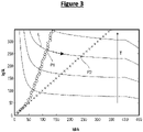
- Figure 3 illustrates the torque T according to the direct and quadrature currents iq, id. More precisely, isotorque lines (such as the line L) are illustrated. The torque T increases in the direction indicated by the solid arrow. Figure 3 also illustrates MTPA points (circles) and equal direct and quadrature current points (crosses).
- the current determination module 204 would for example achieve MTPA and therefore select the direct and quadrature current targets of point P1.
- the current determination module 204 would select another point of isotorque line L with a decreased quadrature current target iq*, i.e. on the portion of the isotorque line L indicated by a dashed arrow on figure 3 .
- the current determination module 204 could be configured to set the direct and quadrature current targets as equals and therefore select the direct and quadrature current targets of point P2.
- the equal direct and quadrature currents points have a decreased quadrature current relative to MTPA points.
- the current determination module 204 may be configured to set the direct and quadrature current targets as equals in the safeguard mode of operation.
- Imax is usually determined by the inverter 100 and its maximum current capability. It can also be determined by the motor or by a project-requirements.
- stator current is 2/3 of the maximum stator current Imax and the torque is 198 Nm and achieved for a slip of 2 Hz (point P3).
- a lower slip 1,242 Hz may be used to maintain the torque at 198 Nm (point P4).
- This decreased slip leads in this example to a 40% decrease of the rotor losses.
- the temperature of the rotor may decrease. This is at the expenses of the stator losses which, in the described example, are increased by 225% so that the stator temperature may increase.
- such temperature increase may be considered acceptable, especially as the stator may be more easily cooled than the rotor.
- the current determination module 204 may be configured to set the direct and quadrature current targets to reach the maximum stator current, with a slip allowing to reach the torque target T*.
- the control device 116 may comprise a computer device comprising a data processing unit (such as a microprocessor) and a main memory accessible by the processing unit.
- the computer device further comprises a computer program containing instructions for the processing unit, to implement the functions of the previously described modules.
- This computer program is for example intended to be loaded into the main memory, so that the processing unit may execute its instructions.
- all or part of these modules could be implemented in the form of hardware modules, that is to say in the form of an electronic circuit, for example micro-wired, not involving a computer program.
- the torque target T* may not be explicitly determined by the control device 116.
- the control device 116 could be configured to determine the direct and quadrature current targets id*, iq* directly from the speed target and the speed of the rotor.
Abstract
Description
- The present invention relates to an inverter, as well as an electric drive and a vehicle comprising such an inverter. The present invention also relates to a method for controlling controllable switches of an inverter and a corresponding computer program product. It is especially intended be used in an automotive vehicle.
- Inverters are used to generate an AC voltage from a DC voltage provided, for instance, from a battery. The AC voltage may be used to drive an asynchronous electric motor comprising a stator and a rotor. In some circumstances, the rotor may overheat.
- An object of the invention is to allow to prevent overheating of the rotor.
- The object of the invention may be solved by an inverter comprising:
- input terminals;
- output terminals;
- controllable switches connected to the input terminals and to the output terminals;
- a control device configured to control the controllable switches so as to convert a DC voltage at the input terminals into an AC voltage at the output terminals intended to drive an asynchronous electric motor to achieve a target torque, selectively:
- in a first mode of operation in which the target torque is determined according to a torque determination method, and
- in response to a rotor temperature, in a second mode of operation in which losses in the rotor are decreased relative to the first mode of operation while the target torque remains determined according to the torque determination method of the first mode of operation.
- Thanks to the invention, the rotor temperature may be reduced with the reduction of the rotor losses in the second mode of operation, without changing the target torque relative to the first mode of operation.
- This is advantageous with respect to the solution consisting in reducing the torque when either the stator or the rotor is too hot. In fact, reducing the torque would result in a reduction of the stator losses as well as in a reduction of the rotor losses However, in particular for electric vehicles where the wheels are driven by the motor, a loss of torque would result in a loss of acceleration, which could impact ease of driving or even security, for instance when torque is needed for taking over a truck. Furthermore, the invention may also allow to simplify a rotor cooling system.
- Some further optional features of the invention which can be used together or separately are developed below.
- In the second mode of operation, the control device may be configured to control the controllable switches in order to increase loses in a stator of the motor, relative to the first mode of operation.
- In the second mode of operation, the control device may be configured to control the controllable switches in order to decrease a slip of the motor, relative to the first mode of operation.
- In the second mode of operation, the control device may be configured to control the controllable switches in order to decrease a stator quadrature current, relative to the first mode of operation. With this feature, the invention may be easily implemented because the direct and quadrature current are parameters that are generally controlled to drive the motor.
- The control device may be configured to pass from the first mode of operation to the second mode of operation when the rotor temperature passes above a predefined threshold. This feature offers a simple condition to switch to the second mode of operation to avoid overheating of the rotor.
- The control device may be configured to pass from the first mode of operation to the second mode of operation according to a stator temperature of the motor, in addition to the rotor temperature. With this feature, it is possible to avoid switching to the second mode of operation in situations it could be at the expense of the stator.
- The control device may be configured to pass from the first mode of operation to the second mode of operation when the stator temperature is under a predefined threshold. This feature offers a simple condition to switch to the second mode of operation to avoid overheating of the rotor, while ensuring that the stator is able to support the second mode of operation.
- In the first mode of operation, the control device may be configured to control the controllable switches according to a Maximum Torque Per Ampere method to reach the torque target. With this feature, when the rotor temperature is considered normal, an efficient control of the motor may be achieved.
- The invention also relates to an electric drive comprising an inverter according to the invention and an electric motor driven by the inverter. The motor is preferably an induction motor.
- The invention also relates to a vehicle comprising wheels and an electric drive according to the invention for driving, at least indirectly, at least one of the wheels.
- The invention also relates to a method for controlling controllable switches of an inverter, the controllable switches being connected to input terminals and to output terminals of the inverter, the method comprising controlling the controllable switches so as to convert a DC voltage at the input terminals into an AC voltage at the output terminals intended to drive an asynchronous electric motor to achieve a target torque:
- in a first mode of operation in which the target torque is determined according to a torque determination method, and
- in response to a rotor temperature, in a second mode of operation in which losses in the rotor are decreased relative to the first mode of operation while the target torque remains determined according to the torque determination method of the first mode of operation.
- The invention also relates to a computer program product comprising instructions which, when the program is executed by a computer, cause the computer to carry out a method for controlling an inverter according to the invention.
- The present invention will be described more specifically with reference to the following drawings, in which:
-
Figure 1 is a schematic view showing an embodiment of a vehicle comprising an inverter according to the invention, -
Figure 2 is an example of implementation of the inverter offigure 1 , -
Figure 3 is a graph showing a torque of a motor driven by the inverter, as a function of a direct and quadrature current of the motor, and -
Figure 4 is a graph the torque versus a slip of the motor, for two different mode of operation of the inverter. - Referring to
figure 1 , avehicle 100 according to the invention will now be described. In the described example, thevehicle 100 is an automotive vehicle. - The
vehicle 100 compriseswheels 102 and anelectric drive 104 configured to drive at least one of thewheels 102 at least indirectly. Thevehicle 100 further comprises aDC voltage source 106, such as a battery, for electrically powering theelectric drive 104. TheDC voltage source 106 is configured to provide a DC voltage E. - The
electric drive 104 comprises an electricasynchronous motor 108 and aninverter 110 configured to drive themotor 108, for instance by supplying electric power. For example, themotor 108 is a rotary electric motor comprising a stator and a rotor configured to rotate around a rotation axis with respect to the stator. The motor has a main inductance Lh. For the embodiment described, themotor 108 is an induction motor. - The stator is provided with stator phases. In the described example, the
motor 108 is a three-phase electric motor comprising three stator phases. Thestator 108 has p pole-pairs of phases. - The
inverter 110 is intended to drive the motor so that phase currents flows respectively in the stator phases, so as to produce a rotating magnetic field rotating around the rotation axis. This stator currents may be considered as vectors so that the resulting current vector may be expressed in a rotating frame through a direct-quadrature-zero (DQZ) transformation or equivalent transformations, as direct current id and quadrature current iq. - Since the
motor 108 is an induction motor for the present embodiment, the rotor must rotate at a speed lower than a speed the magnetic field in order to produce torque. This difference is defined as the slip of themotor 108, expressed for example as a frequency difference. - The
inverter 110 comprises input terminals IT+, IT- connected to theDC voltage source 106 so that the DC voltage E is present at the input terminals IT+, IT-. More precisely, the input terminals IT+, IT- include a positive input terminal IT+ connected to a positive terminal of theDC voltage source 106 and a negative input terminal IT- connected to a negative terminal of theDC voltage source 106 and to an electrical ground GND. - The
inverter 110 further comprises output terminals OT connected to themotor 108. An AC voltage is intended to be present at the output terminals OT for powering theelectric motor 108. The AC voltage may be a single or a multiphase AC voltage. In the described example where themotor 108 is a three-phase electric motor, the AC voltage is a three-phase AC voltage. - The
inverter 110 further comprises controllable switches Q, Q', called main switches, connected to the input terminals IT+, IT- and to the output terminals OT. The main switches Q, Q' may be semi-conductor switches comprising for example transistors. Each main switch Q, Q' comprises for example one amongst: a Metal Oxide Semiconductor Field Effect Transistor (MOSFET), an Insulated Gate Bipolar Transistor (IGBT) and a Silicon Carbide MOSFET (SiC MOSFET). - In the described example, the
inverter 110 comprises switch legs 1141-3 respectively associated to the stator phases of themotor 108. Each switch leg 1141-3 comprises a high side (HS) main switch Q' connected to the positive input terminal IT+ and a low side (LS) main switch Q connected to the negative input terminal IT-. The HS main switch Q' and the LS main switch Q are connected to each other at a middle point connected to the output terminal OT connected to the associated stator phase of themotor 108. - Each switch leg 1141-3 is intended to be controlled to commute between two configurations. In the first one, called high side (HS) configuration, the HS main switch Q' is closed (on) and the LS main switch Q is open (off) so that the DC voltage E is essentially applied to the associated stator phase. In the second one, called low side (LS) configuration, the HS main switch Q' is open (off) and the LS main switch Q is closed (on) so that a zero voltage is essentially applied to the associated stator phase.
- The
inverter 110 further comprises acontrol device 116 configured to control the main switches Q, Q' such that the main switches Q, Q' convert the DC voltage E into the AC voltage. In the described example, thecontrol device 116 is configured to commute eachswitch leg 114 between the two configurations mentioned above. - The
electric drive 104 may further comprise temperature sensors for respectively measuring a temperature Tr of the rotor and a temperature Ts of the stator. Alternatively, the rotor temperature Tr and the stator temperature Ts could be estimated instead of being measured. - Referring to
figure 2 , an example ofcontrol device 116 will now be described. In the following description, only the features of thecontrol device 116 useful to understand the invention are described. - The input signal for the
control device 116 is a torque target T* which may be, for instance, provided by controlling a "gas" pedal of thevehicle 100. - The
control device 116 further comprises acurrent determination module 204 configured to determine a stator direct current target id* and a stator quadrature current target iq* from the torque target T*. - The
control device 116 further comprises acommand determination module 206 configured to determine commands for theswitch legs 1141-3 from the direct and quadrature current targets id*, iq*. These commands are intended to make theswitch legs 1141-3 switch between their HS and LS configurations, so that the stator currents reach the targets id*, iq*. For example, the commands are determined according to a space vector modulation. - The
control device 116 is configured to switch from a normal mode of operation to a safeguard mode of operation according to the rotor temperature Tr and, in the described example, the stator temperature Ts. - To this end, the
control device 116 further comprises, in the described example, atemperature monitor module 208 for monitoring the rotor temperature Tr (measured or estimated) and, in the described example, the stator temperature Ts (measured or estimated). When themodule 208 detects that the rotor temperature becomes high (e.g. passes above a predefined threshold) and the stator temperature is low (e.g. is under a predefined threshold), the control device passes from the normal mode of operation to the safeguard mode of operation. - More precisely, in the described example, in the normal mode of operation, the target torque T* is determined according to a torque determination method independent of the rotor temperature Tr, while the
current determination module 204 determines the current targets id*, iq* according to a normal current determination method. For example, this normal current determination method is a Maximum Torque Per Ampere (MTPA) method. - In the safeguard mode of operation, the torque is determined by the same torque determination method than in the normal mode of operation. In this manner, the determined target torque is the same in the normal mode of operation and in the safeguard mode of operation. In particular, during switching of the mode of operation, the torque target T* stays substantially constant if the conditions to determine the torque target T* stay substantially the same. However, in the safeguard mode of operation, the
current determination module 204 determines the current targets id*, iq* so as to decrease the rotor losses relative to the normal mode of operation, while still achieving the target torque T*. For instance, thecurrent determination module 204 determines the current targets id*, iq* so as to decrease the slip. - More precisely, decreasing the slip may be achieved by changing the operating point of the motor, for instance by decreasing the quadrature current iq
- Besides, the torque T of the
asynchronous motor 108 can be expressed by the equation: T = (3/2)*p*Lh(id)*id*iq, where p is the number of pole-pairs of the stator and Lh is the main inductance of the motor 108 (which may be a function of the direct current id). As can be seen from this equation, a same torque can be reached through various values of direct current id and quadrature current iq. As a result, it is possible to decrease the quadrature current iq while still achieving the desired torque. - Therefore, in the described example, the
current determination module 204 determines the current targets id*, iq* so as to decrease the quadrature current target iq* in the safeguard mode of operation relative to the normal mode of operation, while keeping the same torque target T* than in the normal mode of operation. It results that the direct current target id* is increased to compensate the decrease of the quadrature current target iq*. -
Figure 3 illustrates the torque T according to the direct and quadrature currents iq, id. More precisely, isotorque lines (such as the line L) are illustrated. The torque T increases in the direction indicated by the solid arrow.Figure 3 also illustrates MTPA points (circles) and equal direct and quadrature current points (crosses). - Considering that the target torque T* is the one of the isotorque line L, in the normal mode of operation, the
current determination module 204 would for example achieve MTPA and therefore select the direct and quadrature current targets of point P1. On the contrary, in the safeguard mode operation, thecurrent determination module 204 would select another point of isotorque line L with a decreased quadrature current target iq*, i.e. on the portion of the isotorque line L indicated by a dashed arrow onfigure 3 . For example, thecurrent determination module 204 could be configured to set the direct and quadrature current targets as equals and therefore select the direct and quadrature current targets of point P2. In fact, as illustrated onfigure 3 , except for very low torque (where overheat is not likely to occur), the equal direct and quadrature currents points have a decreased quadrature current relative to MTPA points. - Therefore, the
current determination module 204 may be configured to set the direct and quadrature current targets as equals in the safeguard mode of operation. -
Figure 4 illustrates the torque T according to the slip S, in case of MTPA (solid line) and in case a predefined maximum stator current Imax is reached, i.e. id2 + iq2 = Imax2. Imax is usually determined by theinverter 100 and its maximum current capability. It can also be determined by the motor or by a project-requirements. - In the example given on
figure 2 , in case of MPTA, the stator current is 2/3 of the maximum stator current Imax and the torque is 198 Nm and achieved for a slip of 2 Hz (point P3). - When using setting the stator current (i.e. √(id2 + iq2)) to the maximum stator current Imax, a lower slip 1,242 Hz may be used to maintain the torque at 198 Nm (point P4). This decreased slip leads in this example to a 40% decrease of the rotor losses. As a result, the temperature of the rotor may decrease. This is at the expenses of the stator losses which, in the described example, are increased by 225% so that the stator temperature may increase. However, depending on the situation, such temperature increase may be considered acceptable, especially as the stator may be more easily cooled than the rotor.
- Therefore, the
current determination module 204 may be configured to set the direct and quadrature current targets to reach the maximum stator current, with a slip allowing to reach the torque target T*. - The
control device 116 may comprise a computer device comprising a data processing unit (such as a microprocessor) and a main memory accessible by the processing unit. The computer device further comprises a computer program containing instructions for the processing unit, to implement the functions of the previously described modules. - This computer program is for example intended to be loaded into the main memory, so that the processing unit may execute its instructions. Alternatively, all or part of these modules could be implemented in the form of hardware modules, that is to say in the form of an electronic circuit, for example micro-wired, not involving a computer program.
- It will be noted that the invention is not limited to the embodiments described above. It will indeed appear to those skilled in the art that various modifications can be made to the embodiments described above, in the light of the teaching which has just been disclosed.
- For example, the torque target T* may not be explicitly determined by the
control device 116. For example, thecontrol device 116 could be configured to determine the direct and quadrature current targets id*, iq* directly from the speed target and the speed of the rotor. - In the previous detailed description of the invention, the terms used should not be interpreted as limiting the invention to the embodiments presented in the present description, but should be interpreted to include all the equivalents within the reach of those skilled in the art by applying their general knowledge to the implementation of the teaching which has just been disclosed.
Claims (12)
- Inverter (110) comprising:- input terminals (IT+, IT-);- output terminals (OT);- controllable switches (Q, Q') connected to the input terminals (IT+, IT-) and to the output terminals (OT);- a control device (116) configured to control the controllable switches (Q, Q') so as to convert a DC voltage at the input terminals (IT+, IT-) into an AC voltage at the output terminals (OT) intended to drive an asynchronous electric motor (108) to achieve a target torque (T*), selectively:- in a first mode of operation in which the target torque (T*) is determined according to a torque determination method, and- in response to a rotor temperature (Tr), in a second mode of operation in which losses in the rotor are decreased relative to the first mode of operation while the target torque (T*) remains determined according to the torque determination method of the first mode of operation.
- Inverter (110) according to claim 1, wherein, in the second mode of operation, the control device (116) is configured to control the controllable switches (Q, Q') in order to increase loses in a stator of the motor (108), relative to the first mode of operation.
- Inverter (110) according to claim 1 or 2, wherein, in the second mode of operation, the control device (116) is configured to control the controllable switches (Q, Q') in order to decrease a slip of the motor (108), relative to the first mode of operation.
- Inverter (110) according to claim 3, wherein, in the second mode of operation, the control device (116) is configured to control the controllable switches (Q, Q') in order to decrease a stator quadrature current, relative to the first mode of operation.
- Inverter (110) according to any of claims 1 to 4, wherein the control device (116) is configured to pass from the first mode of operation to the second mode of operation when the rotor temperature (Tr) passes above a predefined threshold.
- Inverter (110) according to any of claims 1 to 7, wherein the control device (116) is configured to pass from the first mode of operation to the second mode of operation according to a stator temperature (Ts) of the motor (108), in addition to the rotor temperature (Tr).
- Inverter (110) according to claim 6, wherein the control device (116) is configured to pass from the first mode of operation to the second mode of operation when the stator temperature (Ts) is under a predefined threshold.
- Inverter (110) according to any of claims 1 to 7, wherein, in the first mode of operation, the control device (116) is configured to control the controllable switches (Q, Q') according to a Maximum Torque Per Ampere method to reach the torque target.
- Electric drive (104) comprising an inverter (110) according to any of claims 1 to 8 and an electric motor (108) driven by the inverter (110).
- Vehicle (100) comprising wheels (102) and an electric drive (104) according to claim 9 for driving, at least indirectly, at least one of the wheels (102)
- Method for controlling controllable switches (Q, Q') of an inverter (110), the controllable switches (Q, Q') being connected to input terminals (IT+, IT-) and to output terminals (OT) of the inverter (110), the method comprising controlling the controllable switches (Q, Q') so as to convert a DC voltage at the input terminals (IT+, IT-) into an AC voltage at the output terminals (OT) intended to drive an asynchronous electric motor (108) to achieve a target torque (T*):- in a first mode of operation in which the target torque (T*) is determined according to a torque determination method, and- in response to a rotor temperature (Tr), in a second mode of operation in which losses in the rotor are decreased relative to the first mode of operation while the target torque (T*) remains determined according to the torque determination method of the first mode of operation.
- Computer program product comprising instructions which, when the program is executed by a computer, cause the computer to carry out a method for controlling an inverter according to claim 11.
Applications Claiming Priority (1)
| Application Number | Priority Date | Filing Date | Title |
|---|---|---|---|
| DE102020214224 | 2020-11-12 |
Publications (1)
| Publication Number | Publication Date |
|---|---|
| EP4002681A1 true EP4002681A1 (en) | 2022-05-25 |
Family
ID=77738988
Family Applications (1)
| Application Number | Title | Priority Date | Filing Date |
|---|---|---|---|
| EP21196254.3A Pending EP4002681A1 (en) | 2020-11-12 | 2021-09-13 | Inverter, electric drive, vehicle and method for controlling controllable switches of an inverter and corresponding computer program product |
Country Status (4)
| Country | Link |
|---|---|
| US (1) | US11722091B2 (en) |
| EP (1) | EP4002681A1 (en) |
| JP (1) | JP2022078006A (en) |
| CN (1) | CN114499258A (en) |
Families Citing this family (1)
| Publication number | Priority date | Publication date | Assignee | Title |
|---|---|---|---|---|
| EP4002664A1 (en) * | 2020-11-11 | 2022-05-25 | Valeo Siemens eAutomotive Germany GmbH | Inverter, method for configuring an inverter, method for controlling an inverter and corresponding computer program |
Citations (6)
| Publication number | Priority date | Publication date | Assignee | Title |
|---|---|---|---|---|
| EP2963805A1 (en) * | 2014-06-30 | 2016-01-06 | Rolls-Royce plc | Controlling an ac machine |
| JP2016082709A (en) * | 2014-10-16 | 2016-05-16 | 日産自動車株式会社 | Controller for induction motor |
| US20170302205A1 (en) * | 2014-10-07 | 2017-10-19 | Robert Bosch Gmbh | Control device for an electric machine, a vehicle, and a method |
| WO2019244370A1 (en) * | 2018-06-21 | 2019-12-26 | 株式会社日立産機システム | Induction electric motor overheat monitoring method, induction electric motor monitoring device, and induction electric motor control system |
| US20200313600A1 (en) * | 2017-11-20 | 2020-10-01 | Robert Bosch Gmbh | Method and device for operating an electric machine for outputting a predefined torque and a predefined rotational speed |
| US10819264B1 (en) * | 2020-08-04 | 2020-10-27 | Wolong Electric Group Co. Ltd. | Robust starting system and method for interior permanent magnet synchronous motor control |
Family Cites Families (10)
| Publication number | Priority date | Publication date | Assignee | Title |
|---|---|---|---|---|
| US5796236A (en) * | 1997-06-30 | 1998-08-18 | Reliance Electric Industrial Company | Slip adjuster for use in electrical motor controllers |
| JP4572907B2 (en) * | 2007-03-29 | 2010-11-04 | トヨタ自動車株式会社 | Motor control device, control method, and control program |
| KR100957330B1 (en) | 2007-12-13 | 2010-05-12 | 현대자동차주식회사 | Method for controlling motor torque of HEV |
| US7960928B2 (en) * | 2008-10-15 | 2011-06-14 | Tesla Motors, Inc. | Flux controlled motor management |
| US8773058B2 (en) * | 2010-07-08 | 2014-07-08 | Tesla Motors, Inc. | Rotor temperature estimation and motor control torque limiting for vector-controlled AC induction motors |
| US8547045B2 (en) | 2011-02-23 | 2013-10-01 | Deere & Company | Method and system controlling an electrical motor with temperature compensation |
| JP5742879B2 (en) * | 2013-05-21 | 2015-07-01 | トヨタ自動車株式会社 | Rotating electric machine control device for vehicle |
| US9106172B2 (en) | 2013-06-28 | 2015-08-11 | Horiba Instruments Incorporated | Electric machine temperature control |
| JP7052373B2 (en) | 2018-01-23 | 2022-04-12 | 株式会社デンソー | AC motor control device |
| AT522279B1 (en) | 2019-03-26 | 2020-12-15 | Avl List Gmbh | Method for operating a drive device, computer program product, drive device and motor vehicle |
-
2021
- 2021-09-13 EP EP21196254.3A patent/EP4002681A1/en active Pending
- 2021-10-27 CN CN202111256669.3A patent/CN114499258A/en active Pending
- 2021-11-10 US US17/454,348 patent/US11722091B2/en active Active
- 2021-11-11 JP JP2021184220A patent/JP2022078006A/en active Pending
Patent Citations (6)
| Publication number | Priority date | Publication date | Assignee | Title |
|---|---|---|---|---|
| EP2963805A1 (en) * | 2014-06-30 | 2016-01-06 | Rolls-Royce plc | Controlling an ac machine |
| US20170302205A1 (en) * | 2014-10-07 | 2017-10-19 | Robert Bosch Gmbh | Control device for an electric machine, a vehicle, and a method |
| JP2016082709A (en) * | 2014-10-16 | 2016-05-16 | 日産自動車株式会社 | Controller for induction motor |
| US20200313600A1 (en) * | 2017-11-20 | 2020-10-01 | Robert Bosch Gmbh | Method and device for operating an electric machine for outputting a predefined torque and a predefined rotational speed |
| WO2019244370A1 (en) * | 2018-06-21 | 2019-12-26 | 株式会社日立産機システム | Induction electric motor overheat monitoring method, induction electric motor monitoring device, and induction electric motor control system |
| US10819264B1 (en) * | 2020-08-04 | 2020-10-27 | Wolong Electric Group Co. Ltd. | Robust starting system and method for interior permanent magnet synchronous motor control |
Also Published As
| Publication number | Publication date |
|---|---|
| CN114499258A (en) | 2022-05-13 |
| US11722091B2 (en) | 2023-08-08 |
| JP2022078006A (en) | 2022-05-24 |
| US20220149768A1 (en) | 2022-05-12 |
Similar Documents
| Publication | Publication Date | Title |
|---|---|---|
| US8054031B2 (en) | Converter device, rotating electrical machine control device, and drive device | |
| US10886867B2 (en) | Inverter control device | |
| US8278855B2 (en) | Controller of motor preventing an increase in inverter loss | |
| US9559630B2 (en) | System and method for controlling modulation of an inverter | |
| US8310186B2 (en) | Apparatus for carrying out improved control of rotary machine | |
| US9543868B2 (en) | Apparatus for controlling rotary electric machine | |
| US20120032620A1 (en) | Control device | |
| EP3651353B1 (en) | Inverter control device | |
| US20180175766A1 (en) | Motor driving device | |
| US10727776B2 (en) | Motor control device | |
| EP4002681A1 (en) | Inverter, electric drive, vehicle and method for controlling controllable switches of an inverter and corresponding computer program product | |
| JP6610381B2 (en) | Inverter control device | |
| US20210257947A1 (en) | Driving device for rotating electric machine | |
| CN111971888A (en) | Power conversion device | |
| JP4798638B2 (en) | Control device for synchronous motor | |
| US11711014B2 (en) | Electric-power conversion apparatus | |
| US20190199268A1 (en) | Motor control device | |
| US7843156B2 (en) | Method and apparatus for active voltage control of electric motors | |
| US20240056015A1 (en) | Inverter, electric drive, vehicle and method for controlling controllable switches of an inverter and corresponding computer program product | |
| JP7278926B2 (en) | Electric motor control device, electric vehicle, electric motor control method | |
| US20210313920A1 (en) | Control unit, control circuit and motor vehicle | |
| JP2007274764A (en) | Apparatus and method for controlling three-phase brushless dc motor | |
| JP2022060914A (en) | Device and method for performing drive control of induction motor |
Legal Events
| Date | Code | Title | Description |
|---|---|---|---|
| PUAI | Public reference made under article 153(3) epc to a published international application that has entered the european phase |
Free format text: ORIGINAL CODE: 0009012 |
|
| STAA | Information on the status of an ep patent application or granted ep patent |
Free format text: STATUS: THE APPLICATION HAS BEEN PUBLISHED |
|
| AK | Designated contracting states |
Kind code of ref document: A1 Designated state(s): AL AT BE BG CH CY CZ DE DK EE ES FI FR GB GR HR HU IE IS IT LI LT LU LV MC MK MT NL NO PL PT RO RS SE SI SK SM TR |
|
| RAP3 | Party data changed (applicant data changed or rights of an application transferred) |
Owner name: VALEO EAUTOMOTIVE GERMANY GMBH |
|
| STAA | Information on the status of an ep patent application or granted ep patent |
Free format text: STATUS: REQUEST FOR EXAMINATION WAS MADE |
|
| 17P | Request for examination filed |
Effective date: 20221125 |
|
| RBV | Designated contracting states (corrected) |
Designated state(s): AL AT BE BG CH CY CZ DE DK EE ES FI FR GB GR HR HU IE IS IT LI LT LU LV MC MK MT NL NO PL PT RO RS SE SI SK SM TR |
|
| P01 | Opt-out of the competence of the unified patent court (upc) registered |
Effective date: 20230528 |
|
| GRAP | Despatch of communication of intention to grant a patent |
Free format text: ORIGINAL CODE: EPIDOSNIGR1 |
|
| STAA | Information on the status of an ep patent application or granted ep patent |
Free format text: STATUS: GRANT OF PATENT IS INTENDED |
|
| INTG | Intention to grant announced |
Effective date: 20231215 |
|
| GRAS | Grant fee paid |
Free format text: ORIGINAL CODE: EPIDOSNIGR3 |