EP4002574A1 - High-voltage battery module including external bridge bus bar - Google Patents
High-voltage battery module including external bridge bus bar Download PDFInfo
- Publication number
- EP4002574A1 EP4002574A1 EP20886274.8A EP20886274A EP4002574A1 EP 4002574 A1 EP4002574 A1 EP 4002574A1 EP 20886274 A EP20886274 A EP 20886274A EP 4002574 A1 EP4002574 A1 EP 4002574A1
- Authority
- EP
- European Patent Office
- Prior art keywords
- battery module
- vertical plate
- disposed
- bus bar
- frame
- Prior art date
- Legal status (The legal status is an assumption and is not a legal conclusion. Google has not performed a legal analysis and makes no representation as to the accuracy of the status listed.)
- Granted
Links
Images

Classifications
-
- H—ELECTRICITY
- H01—ELECTRIC ELEMENTS
- H01M—PROCESSES OR MEANS, e.g. BATTERIES, FOR THE DIRECT CONVERSION OF CHEMICAL ENERGY INTO ELECTRICAL ENERGY
- H01M50/00—Constructional details or processes of manufacture of the non-active parts of electrochemical cells other than fuel cells, e.g. hybrid cells
- H01M50/50—Current conducting connections for cells or batteries
- H01M50/502—Interconnectors for connecting terminals of adjacent batteries; Interconnectors for connecting cells outside a battery casing
- H01M50/507—Interconnectors for connecting terminals of adjacent batteries; Interconnectors for connecting cells outside a battery casing comprising an arrangement of two or more busbars within a container structure, e.g. busbar modules
-
- H—ELECTRICITY
- H01—ELECTRIC ELEMENTS
- H01M—PROCESSES OR MEANS, e.g. BATTERIES, FOR THE DIRECT CONVERSION OF CHEMICAL ENERGY INTO ELECTRICAL ENERGY
- H01M50/00—Constructional details or processes of manufacture of the non-active parts of electrochemical cells other than fuel cells, e.g. hybrid cells
- H01M50/20—Mountings; Secondary casings or frames; Racks, modules or packs; Suspension devices; Shock absorbers; Transport or carrying devices; Holders
- H01M50/204—Racks, modules or packs for multiple batteries or multiple cells
-
- H—ELECTRICITY
- H01—ELECTRIC ELEMENTS
- H01M—PROCESSES OR MEANS, e.g. BATTERIES, FOR THE DIRECT CONVERSION OF CHEMICAL ENERGY INTO ELECTRICAL ENERGY
- H01M50/00—Constructional details or processes of manufacture of the non-active parts of electrochemical cells other than fuel cells, e.g. hybrid cells
- H01M50/20—Mountings; Secondary casings or frames; Racks, modules or packs; Suspension devices; Shock absorbers; Transport or carrying devices; Holders
- H01M50/204—Racks, modules or packs for multiple batteries or multiple cells
- H01M50/207—Racks, modules or packs for multiple batteries or multiple cells characterised by their shape
- H01M50/211—Racks, modules or packs for multiple batteries or multiple cells characterised by their shape adapted for pouch cells
-
- H—ELECTRICITY
- H01—ELECTRIC ELEMENTS
- H01M—PROCESSES OR MEANS, e.g. BATTERIES, FOR THE DIRECT CONVERSION OF CHEMICAL ENERGY INTO ELECTRICAL ENERGY
- H01M50/00—Constructional details or processes of manufacture of the non-active parts of electrochemical cells other than fuel cells, e.g. hybrid cells
- H01M50/50—Current conducting connections for cells or batteries
- H01M50/502—Interconnectors for connecting terminals of adjacent batteries; Interconnectors for connecting cells outside a battery casing
- H01M50/503—Interconnectors for connecting terminals of adjacent batteries; Interconnectors for connecting cells outside a battery casing characterised by the shape of the interconnectors
-
- H—ELECTRICITY
- H01—ELECTRIC ELEMENTS
- H01M—PROCESSES OR MEANS, e.g. BATTERIES, FOR THE DIRECT CONVERSION OF CHEMICAL ENERGY INTO ELECTRICAL ENERGY
- H01M50/00—Constructional details or processes of manufacture of the non-active parts of electrochemical cells other than fuel cells, e.g. hybrid cells
- H01M50/50—Current conducting connections for cells or batteries
- H01M50/543—Terminals
- H01M50/547—Terminals characterised by the disposition of the terminals on the cells
- H01M50/548—Terminals characterised by the disposition of the terminals on the cells on opposite sides of the cell
-
- H—ELECTRICITY
- H01—ELECTRIC ELEMENTS
- H01M—PROCESSES OR MEANS, e.g. BATTERIES, FOR THE DIRECT CONVERSION OF CHEMICAL ENERGY INTO ELECTRICAL ENERGY
- H01M50/00—Constructional details or processes of manufacture of the non-active parts of electrochemical cells other than fuel cells, e.g. hybrid cells
- H01M50/50—Current conducting connections for cells or batteries
- H01M50/572—Means for preventing undesired use or discharge
-
- H—ELECTRICITY
- H01—ELECTRIC ELEMENTS
- H01M—PROCESSES OR MEANS, e.g. BATTERIES, FOR THE DIRECT CONVERSION OF CHEMICAL ENERGY INTO ELECTRICAL ENERGY
- H01M2200/00—Safety devices for primary or secondary batteries
-
- Y—GENERAL TAGGING OF NEW TECHNOLOGICAL DEVELOPMENTS; GENERAL TAGGING OF CROSS-SECTIONAL TECHNOLOGIES SPANNING OVER SEVERAL SECTIONS OF THE IPC; TECHNICAL SUBJECTS COVERED BY FORMER USPC CROSS-REFERENCE ART COLLECTIONS [XRACs] AND DIGESTS
- Y02—TECHNOLOGIES OR APPLICATIONS FOR MITIGATION OR ADAPTATION AGAINST CLIMATE CHANGE
- Y02E—REDUCTION OF GREENHOUSE GAS [GHG] EMISSIONS, RELATED TO ENERGY GENERATION, TRANSMISSION OR DISTRIBUTION
- Y02E60/00—Enabling technologies; Technologies with a potential or indirect contribution to GHG emissions mitigation
- Y02E60/10—Energy storage using batteries
Definitions
- the present invention relates to a high-voltage battery module including an outer bridge bus bar, and more particularly to a high-voltage battery module of 60V or higher to which an outer bridge bus bar structure is applied.
- a secondary battery applied to electric vehicles is generally used in a form in which a plurality of secondary battery cells (hereinafter referred to as "cells") is assembled.
- the secondary battery is used in the form of a battery module in which a plurality of cells is connected to each other in series/parallel or in the form of a battery pack in which a plurality of battery modules is coupled to each other.
- a battery module used in electric vehicles a plurality of cells is connected to each other in series, in parallel, or in series and parallel in order to provide output and capacity required by middle- or large-sized devices.
- the structure of the battery module must be stably maintained against vibration and impact in consideration of the characteristics of the vehicles.
- Patent Document 1 discloses a conventional middle- or large-sized battery module, wherein electrode leads of a plurality of cells in the battery module are fixed to a plurality of bus bars, each of which is provided in the form of a metal plate, in the state of being electrically connected thereto.
- Patent Document 1 discloses a mono frame type battery module, in which bus bars and a sensing means are mounted to a cell assembly constituted by stacked cells, and all thereof are received in a mono frame provided in the form of a quadrangular pipe.
- a mono frame type battery module pouch-shaped battery cells, which are very easy to stack, are mainly used.
- the battery module includes a cell assembly constituted by stacked pouch-shaped secondary battery cells, each of the cells having electrode leads formed in opposite directions, a bus bar frame constituted by a first vertical plate and a second vertical plate, disposed at opposite sides of the cell assembly corresponding to the positions of the electrode leads of each of the cells, and an upper plate connected to the first vertical plate and to the second vertical plate, the upper plate being disposed above the cell assembly, and a mono frame configured to allow the cell assembly, to which the bus bar frame is mounted, to be disposed in a space defined therein by insertion thereinto, the mono frame being formed in the shape of a quadrangular pipe.
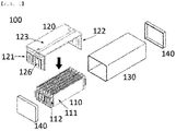
- FIG. 1 is an exploded perspective view schematically showing the structure of a conventional battery module.
- the battery module 100 includes a cell assembly 110 constituted by stacked cells 111, each of the cells having electrode leads 112 formed in opposite directions; a bus bar frame 120 constituted by a first vertical plate 121 and a second vertical plate 122, disposed at opposite sides of the cell assembly 110 corresponding to the positions of the electrode leads 112 of each of the cells 111, and an upper plate 123 connected to the first vertical plate 121 and to the second vertical plate 122, the upper plate being disposed above the cell assembly 110; and a mono frame 130 configured to allow the cell assembly 110, to which the bus bar frame 120 is mounted, to be disposed in a space defined therein by insertion thereinto, the mono frame being formed in the shape of a quadrangular pipe. Side frames 140 are coupled to the mono frame 130, whereby the battery module 100 is completed.
- a plurality of bus bars 126 is provided at the outer surface of each of the first vertical plate 121 and the second vertical plate 122, and each of the electrode leads 112 of the cells 111 is electrically connected to a corresponding one of the bus bars 126 through a corresponding one of slots formed in the first vertical plate 121 and the second vertical plate 122.
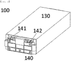
- FIG. 2 is a front perspective view showing a first side frame 140 of the conventional battery module 100.
- Final input and output terminals 141 and 142 are provided at the first side frame 140.
- the final input and output terminals 141 and 142 may be provided by protruding some of the bus bars 126 or by inserting separate bus bars into some of the bus bars 126.
- Battery modules have been applied to middle- or large-sized vehicles, such as trucks, in addition to small-sized vehicles. As a result, the outputs of the battery modules have also been increased, and therefore high-voltage battery modules of 60V or higher have been used in recent years. In this case, voltage provided through the final input and output terminals is 60V, whereby a danger of accident greatly increases compared to conventional battery modules.
- the skin of the human body has a resistance value of about 4,000 ⁇ when the skin is dry, and the resistance value is reduced to about 2,000 ⁇ when the skin is wet.
- a current of 25 mA flows in the human body when the skin is dry
- a current of 50 mA flows in the human body when the skin is wet.
- a current of 10 to 20 mA or higher flows in the human body, the muscles of the human body become stiff, whereby it is not possible for the human body to escape from the place at which the human body receives the electric shock.
- Patent Document 1 Korean Patent Application Publication No. 2019-0114406
- the present invention has been made in view of the above problems, and it is an object of the present invention to provide a high-voltage battery module capable of removing dangerous factors that may injure the human body during manufacture and transportation of the high-voltage battery module and being used in the state in which restrictions are minimized.
- a battery module including a cell assembly constituted by stacked pouch-shaped secondary battery cells, each of the cells having electrode leads formed in opposite directions, a first vertical plate and a second vertical plate disposed at opposite sides of the cell assembly corresponding to the positions of the electrode leads of each of the cells, and a plurality of bus bars provided at each of the first vertical plate and the second vertical plate, each of the electrode leads of the cells being electrically connected to a corresponding one of the bus bars,
- final input and output terminals of the battery module or bus bars connected to the final input and output terminals are disposed at the first vertical plate, and bus bars electrically separated from each other are disposed at the second vertical plate, the bus bars disposed at the second vertical plate in the state of being electrically separated from each other being connected to each other via a separate bridge bus bar.
- the battery module may further include a bus bar frame constituted by an upper plate connected to the first vertical plate and the second vertical plate, the upper plate being disposed above the cell assembly, and a mono frame configured to allow the cell assembly having the bus bar frame mounted therein to be disposed in a space defined therein by insertion thereinto, the mono frame being formed in the shape of a quadrangular pipe.
- a bus bar frame constituted by an upper plate connected to the first vertical plate and the second vertical plate, the upper plate being disposed above the cell assembly
- a mono frame configured to allow the cell assembly having the bus bar frame mounted therein to be disposed in a space defined therein by insertion thereinto, the mono frame being formed in the shape of a quadrangular pipe.
- the battery module may further include a first side frame and a second side frame coupled to the mono frame, the mono frame being configured to allow the cell assembly having the bus bar frame mounted therein to be disposed in the space defined therein by insertion thereinto, the mono frame being formed in the shape of the quadrangular pipe, the first side frame and the second side frame being configured to protect outer surfaces of the first vertical plate and the second vertical plate of the mono frame from the outside.
- a bridge coupling unit configured to allow the bridge bus bar to be coupled thereto may be disposed at the upper end of the battery module. At this time, the bridge coupling unit may be provided at the upper end of the second vertical plate.
- the bridge bus bar may be configured to electrically interconnect the bus bars disposed at the second vertical plate in the state of being electrically separated from each other by manipulation outside the battery module.
- bus bars may be disposed at the second vertical plate in the state of being electrically separated from each other.
- bridge bus bars and bridge coupling units are provided.
- a battery pack including the battery module.
- the present invention may be provided in the state in which an arbitrary combination of the invention is possible.
- the present invention is an improvement to the second vertical plate and the second side frame of the conventional battery module, and a description will be given based thereon.
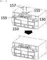
- FIG. 3 is a front perspective view showing a second side frame according to the present invention.
- FIG. 4 is an enlarged view schematically showing a bridge coupling unit according to the present invention.
- the bridge coupling unit 159 is disposed at the upper end of the battery module. Portions of outer exposure bus bars that may extend from the bus bars of the second vertical plate 122 or may be connected to the bus bars of the second vertical plate 122 are located at the bridge coupling unit 159. In the upper figure of FIG. 3 , the bus bars are electrically separated from each other.
- the bus bars which are separated from each other, are connected to each other via a bridge bus bar 155, which is flat and rectangular, and the bridge bus bar is fixed to the bus bars using assembly screws 157.
- the lower figure of FIG. 3 shows the state in which the above components are coupled to each other.
- FIG. 4 shows the enlarged state of the bridge coupling unit 159.
- FIG. 4 shows an embodiment of outer connection bus bars 153, which are outer exposure bus bars that can be connected to the bus bars of the second vertical plate 122.
- Each of the outer connection bus bars 153 is made of a conductive material, is fixed to a corresponding upper protruding portion of the second vertical plate 122, which is made of a non-conductive material, and is connected to a bus bar directly connected to a corresponding one of the electrode leads of the second vertical plate 112.
- Each of the outer connection bus bars 153 may be manufactured as a separate part, or may be integrally formed with a bus bar directly connected to a corresponding one of the electrode leads of the second vertical plate 112.
- bridge bus bar 60V has been mentioned as an example, and only one bridge bus bar is shown in the drawings by way of example. In the case of higher voltage and in a high-humidity work environment, however, one or more bridge bus bars may be used even in a conventional low-voltage battery module in order to extend the range thereof.
- the present invention has been made in view of the above problems, and it is possible to provide a high-voltage battery module capable of removing dangerous factors that may injure the human body during manufacture and transportation of the high-voltage battery module and being used in the state in which restrictions are minimized.
- the present invention has an advantage in that the electrical connection of a cell assembly disposed in the battery module is divided into two or more parts before the cell assembly is used to finally supply electricity, whereby it is possible to reduce the voltage of the battery module to less than a voltage that may injure the human body.
Landscapes
- Chemical & Material Sciences (AREA)
- Chemical Kinetics & Catalysis (AREA)
- Electrochemistry (AREA)
- General Chemical & Material Sciences (AREA)
- Battery Mounting, Suspending (AREA)
- Connection Of Batteries Or Terminals (AREA)
Abstract
Description
- This application claims the benefit of priority to
Korean Patent Application No. 2019-0146881 filed on November 15, 2019 - The present invention relates to a high-voltage battery module including an outer bridge bus bar, and more particularly to a high-voltage battery module of 60V or higher to which an outer bridge bus bar structure is applied.
- Unlike small-sized mobile devices, such as smartphones, middle- or large-sized devices, such as electric vehicles, require a high-output, large-capacity battery. A secondary battery applied to electric vehicles is generally used in a form in which a plurality of secondary battery cells (hereinafter referred to as "cells") is assembled. The secondary battery is used in the form of a battery module in which a plurality of cells is connected to each other in series/parallel or in the form of a battery pack in which a plurality of battery modules is coupled to each other.
- For a battery module used in electric vehicles, a plurality of cells is connected to each other in series, in parallel, or in series and parallel in order to provide output and capacity required by middle- or large-sized devices. In addition, the structure of the battery module must be stably maintained against vibration and impact in consideration of the characteristics of the vehicles.
- Patent Document 1 discloses a conventional middle- or large-sized battery module, wherein electrode leads of a plurality of cells in the battery module are fixed to a plurality of bus bars, each of which is provided in the form of a metal plate, in the state of being electrically connected thereto.
- Patent Document 1 discloses a mono frame type battery module, in which bus bars and a sensing means are mounted to a cell assembly constituted by stacked cells, and all thereof are received in a mono frame provided in the form of a quadrangular pipe. For such a mono frame type battery module, pouch-shaped battery cells, which are very easy to stack, are mainly used.
- In Patent Document 1, the battery module includes a cell assembly constituted by stacked pouch-shaped secondary battery cells, each of the cells having electrode leads formed in opposite directions, a bus bar frame constituted by a first vertical plate and a second vertical plate, disposed at opposite sides of the cell assembly corresponding to the positions of the electrode leads of each of the cells, and an upper plate connected to the first vertical plate and to the second vertical plate, the upper plate being disposed above the cell assembly, and a mono frame configured to allow the cell assembly, to which the bus bar frame is mounted, to be disposed in a space defined therein by insertion thereinto, the mono frame being formed in the shape of a quadrangular pipe.
-
FIG. 1 is an exploded perspective view schematically showing the structure of a conventional battery module. - Referring to
FIG. 1 , thebattery module 100 includes acell assembly 110 constituted bystacked cells 111, each of the cells having electrode leads 112 formed in opposite directions; abus bar frame 120 constituted by a firstvertical plate 121 and a secondvertical plate 122, disposed at opposite sides of thecell assembly 110 corresponding to the positions of the electrode leads 112 of each of thecells 111, and anupper plate 123 connected to the firstvertical plate 121 and to the secondvertical plate 122, the upper plate being disposed above thecell assembly 110; and amono frame 130 configured to allow thecell assembly 110, to which thebus bar frame 120 is mounted, to be disposed in a space defined therein by insertion thereinto, the mono frame being formed in the shape of a quadrangular pipe.Side frames 140 are coupled to themono frame 130, whereby thebattery module 100 is completed. - A plurality of
bus bars 126 is provided at the outer surface of each of the firstvertical plate 121 and the secondvertical plate 122, and each of the electrode leads 112 of thecells 111 is electrically connected to a corresponding one of thebus bars 126 through a corresponding one of slots formed in the firstvertical plate 121 and the secondvertical plate 122. -
FIG. 2 is a front perspective view showing afirst side frame 140 of theconventional battery module 100. Final input andoutput terminals first side frame 140. The final input andoutput terminals bus bars 126 or by inserting separate bus bars into some of thebus bars 126. - Battery modules have been applied to middle- or large-sized vehicles, such as trucks, in addition to small-sized vehicles. As a result, the outputs of the battery modules have also been increased, and therefore high-voltage battery modules of 60V or higher have been used in recent years. In this case, voltage provided through the final input and output terminals is 60V, whereby a danger of accident greatly increases compared to conventional battery modules.
- There are current, current flow time, and current flow paths as factors that determine the degree of disaster due to electric shock. However, the most important factor is current, rather than voltage. When alternating current flows in a human body, the human body may suffer considerable pain at a current of 5 mA, and death may occur at a current of 50 mA.
- In general, the skin of the human body has a resistance value of about 4,000Ω when the skin is dry, and the resistance value is reduced to about 2,000Ω when the skin is wet. In the case in which the human body receives electric shock at a voltage of 100V, a current of 25 mA flows in the human body when the skin is dry, and a current of 50 mA flows in the human body when the skin is wet. In the case in which a current of 10 to 20 mA or higher flows in the human body, the muscles of the human body become stiff, whereby it is not possible for the human body to escape from the place at which the human body receives the electric shock.
- In the case in which the voltage of a conventional battery module is 25V and the human body is dry, a low current of 6.25 mA (25V/4000Q) flows in the human body. Even in the case in which a worker comes into contact with the battery module, therefore, the worker may easily escape therefrom. In the case of a battery module of 60V, which has been introduced in recent years, however, a current of 15 mA or higher flows in the human body. In the case in which the worker receives electric shock, therefore, the muscles of the worker become stiff, whereby it is not possible for the worker to escape from the place at which the worker receives the electric shock.
- Demand for high-voltage battery modules has gradually increased, and therefore there is a need for a plan capable of securing the safety of high-voltage battery modules, the danger of which has qualitatively greatly increased compared to conventional battery modules.
- (Patent Document 1)
Korean Patent Application Publication No. 2019-0114406 - The present invention has been made in view of the above problems, and it is an object of the present invention to provide a high-voltage battery module capable of removing dangerous factors that may injure the human body during manufacture and transportation of the high-voltage battery module and being used in the state in which restrictions are minimized.
- In accordance with an aspect of the present invention, the above and other objects can be accomplished by the provision of a battery module including a cell assembly constituted by stacked pouch-shaped secondary battery cells, each of the cells having electrode leads formed in opposite directions, a first vertical plate and a second vertical plate disposed at opposite sides of the cell assembly corresponding to the positions of the electrode leads of each of the cells, and a plurality of bus bars provided at each of the first vertical plate and the second vertical plate, each of the electrode leads of the cells being electrically connected to a corresponding one of the bus bars,
- wherein final input and output terminals of the battery module or bus bars connected to the final input and output terminals are disposed at the first vertical plate, and bus bars electrically separated from each other are disposed at the second vertical plate, the bus bars disposed at the second vertical plate in the state of being electrically separated from each other being connected to each other via a separate bridge bus bar.
- The battery module may further include a bus bar frame constituted by an upper plate connected to the first vertical plate and the second vertical plate, the upper plate being disposed above the cell assembly, and a mono frame configured to allow the cell assembly having the bus bar frame mounted therein to be disposed in a space defined therein by insertion thereinto, the mono frame being formed in the shape of a quadrangular pipe.
- The battery module may further include a first side frame and a second side frame coupled to the mono frame, the mono frame being configured to allow the cell assembly having the bus bar frame mounted therein to be disposed in the space defined therein by insertion thereinto, the mono frame being formed in the shape of the quadrangular pipe, the first side frame and the second side frame being configured to protect outer surfaces of the first vertical plate and the second vertical plate of the mono frame from the outside.
- A bridge coupling unit configured to allow the bridge bus bar to be coupled thereto may be disposed at the upper end of the battery module. At this time, the bridge coupling unit may be provided at the upper end of the second vertical plate.
- The bridge bus bar may be configured to electrically interconnect the bus bars disposed at the second vertical plate in the state of being electrically separated from each other by manipulation outside the battery module.
- In addition, two or more bus bars may be disposed at the second vertical plate in the state of being electrically separated from each other. Correspondingly, the same number of bridge bus bars and bridge coupling units are provided.
- In accordance with another aspect of the present invention, there is provided a battery pack including the battery module.
- In accordance with a further aspect of the present invention, there is provided a method of using the battery module, wherein the bridge bus bar is not connected until electricity is supplied using the battery module.
- The present invention may be provided in the state in which an arbitrary combination of the invention is possible.
-
-
FIG. 1 is an exploded perspective view schematically showing the structure of a conventional battery module. -
FIG. 2 is a front perspective view showing a first side frame of the conventional battery module. -
FIG. 3 is a front perspective view showing a second side frame according to the present invention. -
FIG. 4 is an enlarged view schematically showing a bridge coupling unit according to the present invention. - Now, preferred embodiments of the present invention will be described in detail with reference to the accompanying drawings such that the preferred embodiments of the present invention can be easily implemented by a person having ordinary skill in the art to which the present invention pertains. In describing the principle of operation of the preferred embodiments of the present invention in detail, however, a detailed description of known functions and configurations incorporated herein will be omitted when the same may obscure the subject matter of the present invention.
- In addition, the same reference numbers will be used throughout the drawings to refer to parts that perform similar functions or operations. In the case in which one part is said to be connected to another part in the specification, not only may the one part be directly connected to the other part, but also, the one part may be indirectly connected to the other part via a further part. In addition, that a certain element is included does not mean that other elements are excluded, but means that such elements may be further included unless mentioned otherwise.
- Hereinafter, the present invention will be described in more detail.
- The present invention is an improvement to the second vertical plate and the second side frame of the conventional battery module, and a description will be given based thereon.
-
FIG. 3 is a front perspective view showing a second side frame according to the present invention. -
FIG. 4 is an enlarged view schematically showing a bridge coupling unit according to the present invention. - The
bridge coupling unit 159 is disposed at the upper end of the battery module. Portions of outer exposure bus bars that may extend from the bus bars of the secondvertical plate 122 or may be connected to the bus bars of the secondvertical plate 122 are located at thebridge coupling unit 159. In the upper figure ofFIG. 3 , the bus bars are electrically separated from each other. - The bus bars, which are separated from each other, are connected to each other via a
bridge bus bar 155, which is flat and rectangular, and the bridge bus bar is fixed to the bus bars using assembly screws 157. The lower figure ofFIG. 3 shows the state in which the above components are coupled to each other. -
FIG. 4 shows the enlarged state of thebridge coupling unit 159.FIG. 4 shows an embodiment of outer connection bus bars 153, which are outer exposure bus bars that can be connected to the bus bars of the secondvertical plate 122. Each of the outer connection bus bars 153 is made of a conductive material, is fixed to a corresponding upper protruding portion of the secondvertical plate 122, which is made of a non-conductive material, and is connected to a bus bar directly connected to a corresponding one of the electrode leads of the secondvertical plate 112. Each of the outer connection bus bars 153 may be manufactured as a separate part, or may be integrally formed with a bus bar directly connected to a corresponding one of the electrode leads of the secondvertical plate 112. - In the present invention, 60V has been mentioned as an example, and only one bridge bus bar is shown in the drawings by way of example. In the case of higher voltage and in a high-humidity work environment, however, one or more bridge bus bars may be used even in a conventional low-voltage battery module in order to extend the range thereof.
- Although the specific details of the present invention have been described in detail, those skilled in the art will appreciate that the detailed description thereof discloses only preferred embodiments of the present invention and thus does not limit the scope of the present invention. Accordingly, those skilled in the art will appreciate that various changes and modifications are possible, without departing from the category and the technical idea of the present invention, and it will be obvious that such changes and modifications fall within the scope of the appended claims.
- As is apparent from the above description, the present invention has been made in view of the above problems, and it is possible to provide a high-voltage battery module capable of removing dangerous factors that may injure the human body during manufacture and transportation of the high-voltage battery module and being used in the state in which restrictions are minimized. In particular, the present invention has an advantage in that the electrical connection of a cell assembly disposed in the battery module is divided into two or more parts before the cell assembly is used to finally supply electricity, whereby it is possible to reduce the voltage of the battery module to less than a voltage that may injure the human body.
-
- 100:
- Battery module
- 110:
- Cell assembly
- 111:
- Cells
- 112:
- Electrode leads
- 120:
- Bus bar fame
- 121:
- First vertical plate
- 122:
- Second vertical plate
- 123:
- Upper plate
- 125:
- Bus bars
- 130:
- Mono frame
- 140:
- First side frame
- 141, 142:
- Final input and output terminals
- 150:
- Second side frame
- 153:
- Outer connection bus bars
- 155:
- Bridge bus bar
- 157:
- Assembly screws
- 159:
- Bridge coupling unit
Claims (9)
- A battery module comprising:a cell assembly constituted by stacked pouch-shaped secondary battery cells, each of the cells having electrode leads formed in opposite directions;a first vertical plate and a second vertical plate disposed at opposite sides of the cell assembly corresponding to positions of the electrode leads of each of the cells; anda plurality of bus bars provided at each of the first vertical plate and the second vertical plate, each of the electrode leads of the cells being electrically connected to a corresponding one of the bus bars, whereinfinal input and output terminals of the battery module or bus bars connected to the final input and output terminals are disposed at the first vertical plate, andbus bars electrically separated from each other are disposed at the second vertical plate, the bus bars disposed at the second vertical plate in a state of being electrically separated from each other being connected to each other via a separate bridge bus bar.
- The battery module according to claim 1, further comprising:a bus bar frame including an upper plate connected to the first vertical plate and the second vertical plate, the upper plate being disposed above the cell assembly; anda mono frame configured to allow the cell assembly having the bus bar frame mounted therein to be disposed in a space defined therein by insertion thereinto, the mono frame being formed in a quadrangular pipe shape.
- The battery module according to claim 2, further comprising a first side frame and a second side frame coupled to the mono frame, the mono frame being configured to allow the cell assembly having the bus bar frame mounted therein to be disposed in the space defined therein by insertion thereinto, the mono frame being formed in the quadrangular pipe shape, the first side frame and the second side frame being configured to protect outer surfaces of the first vertical plate and the second vertical plate of the mono frame from an outside.
- The battery module according to claim 1, wherein a bridge coupling unit configured to allow the bridge bus bar to be coupled thereto is disposed at an upper end of the battery module.
- The battery module according to claim 4, wherein the bridge coupling unit is provided at an upper end of the second vertical plate.
- The battery module according to claim 1, wherein the bridge bus bar is configured to electrically interconnect the bus bars disposed at the second vertical plate in the state of being electrically separated from each other by manipulation outside the battery module.
- The battery module according to claim 1, wherein two or more of the bus bars are disposed at the second vertical plate in the state of being electrically separated from each other.
- A battery pack comprising the battery module according to any one of claims 1 to 7.
- A method of using the battery module according to any one of claims 1 to 7, wherein the bridge bus bar is not connected until electricity is supplied using the battery module.
Applications Claiming Priority (2)
| Application Number | Priority Date | Filing Date | Title |
|---|---|---|---|
| KR1020190146881A KR102811566B1 (en) | 2019-11-15 | 2019-11-15 | High voltage battery module comprising external bridge busbar |
| PCT/KR2020/013961 WO2021096074A1 (en) | 2019-11-15 | 2020-10-14 | High-voltage battery module including external bridge bus bar |
Publications (3)
| Publication Number | Publication Date |
|---|---|
| EP4002574A1 true EP4002574A1 (en) | 2022-05-25 |
| EP4002574A4 EP4002574A4 (en) | 2022-12-28 |
| EP4002574B1 EP4002574B1 (en) | 2024-03-13 |
Family
ID=75912777
Family Applications (1)
| Application Number | Title | Priority Date | Filing Date |
|---|---|---|---|
| EP20886274.8A Active EP4002574B1 (en) | 2019-11-15 | 2020-10-14 | High-voltage battery module including external bridge bus bar |
Country Status (9)
| Country | Link |
|---|---|
| US (1) | US12592455B2 (en) |
| EP (1) | EP4002574B1 (en) |
| JP (1) | JP7371238B2 (en) |
| KR (1) | KR102811566B1 (en) |
| CN (2) | CN112909438B (en) |
| ES (1) | ES2976209T3 (en) |
| HU (1) | HUE066151T2 (en) |
| PL (1) | PL4002574T3 (en) |
| WO (1) | WO2021096074A1 (en) |
Cited By (1)
| Publication number | Priority date | Publication date | Assignee | Title |
|---|---|---|---|---|
| US12592455B2 (en) | 2019-11-15 | 2026-03-31 | Lg Energy Solution, Ltd. | High-voltage battery module including outer bridge bus bar |
Families Citing this family (1)
| Publication number | Priority date | Publication date | Assignee | Title |
|---|---|---|---|---|
| KR20240044683A (en) | 2022-09-29 | 2024-04-05 | 주식회사 엘지에너지솔루션 | Battery module with improved thermal propagation preventing structure |
Family Cites Families (29)
| Publication number | Priority date | Publication date | Assignee | Title |
|---|---|---|---|---|
| JP4053739B2 (en) | 2001-05-18 | 2008-02-27 | 矢崎総業株式会社 | Battery |
| JP2003123734A (en) * | 2001-10-16 | 2003-04-25 | Auto Network Gijutsu Kenkyusho:Kk | Connection structure between battery terminal and bus bar |
| US8815429B2 (en) | 2009-01-12 | 2014-08-26 | A123 Systems Llc | Busbar supports and methods of their use for battery systems |
| EP2416436B1 (en) * | 2009-04-01 | 2018-02-21 | LG Chem, Ltd. | Voltage-detecting member, and battery module including same |
| JP5537111B2 (en) * | 2009-09-30 | 2014-07-02 | 株式会社東芝 | Secondary battery device |
| JP5770551B2 (en) | 2011-07-22 | 2015-08-26 | 矢崎総業株式会社 | Service plug mounting structure |
| US9368782B2 (en) | 2012-06-06 | 2016-06-14 | Johnson Controls Technology Llc | Manufacturing service disconnect that is part of busbar |
| KR101533991B1 (en) | 2012-09-18 | 2015-07-06 | 주식회사 엘지화학 | Battery Module Assembly |
| KR20140064093A (en) | 2012-11-19 | 2014-05-28 | 주식회사 엘지화학 | Battery module with improved safety and bus bar applied for the same |
| KR20140077811A (en) * | 2012-12-13 | 2014-06-24 | 타이코에이엠피(유) | Battery module |
| JP6210808B2 (en) * | 2013-09-13 | 2017-10-11 | 矢崎総業株式会社 | Busbar module connection structure |
| KR101667519B1 (en) * | 2013-12-17 | 2016-10-28 | 주식회사 엘지화학 | Battery Module having Bus Bar employed with External Input-Output Terminal |
| JP6132937B2 (en) * | 2014-02-14 | 2017-05-24 | 矢崎総業株式会社 | Bus bar module |
| US9705121B2 (en) * | 2014-08-18 | 2017-07-11 | Johnson Controls Technology Company | Lead frame for a battery module |
| KR101750487B1 (en) | 2014-10-31 | 2017-07-03 | 주식회사 엘지화학 | Battery Module Having Mounting Means of Bus Bar and External Input-Output Terminal |
| KR102052672B1 (en) | 2016-02-25 | 2019-12-05 | 주식회사 엘지화학 | Service plug, battery pack comprising the service plug and vehicle comprising the battery pack |
| US11376969B2 (en) | 2016-12-27 | 2022-07-05 | Yura Corporation Co., Ltd. | Bus bar assembly and frame assembly |
| WO2018124494A2 (en) | 2016-12-27 | 2018-07-05 | 주식회사 유라코퍼레이션 | Bus bar assembly and frame assembly |
| EP3565022B1 (en) | 2016-12-27 | 2021-03-10 | Yura Corporation Co., Ltd. | Flexible circuit board and frame assembly including same |
| US10333129B2 (en) * | 2017-01-26 | 2019-06-25 | Te Connectivity Corporation | Buss bar assembly for a battery system |
| KR102065100B1 (en) * | 2017-02-24 | 2020-01-10 | 주식회사 엘지화학 | Battery module |
| KR102033003B1 (en) | 2017-02-28 | 2019-10-16 | 주식회사 유라코퍼레이션 | Frame assembly |
| KR102273184B1 (en) * | 2017-10-10 | 2021-07-05 | 주식회사 엘지에너지솔루션 | Bus bar assembly for connecting electrode lead and Battery module including the same |
| KR102203250B1 (en) | 2017-11-29 | 2021-01-13 | 주식회사 엘지화학 | Battery Module Having End Frame |
| IT201800002775A1 (en) | 2018-02-16 | 2019-08-16 | Ferrari Spa | VEHICLE BATTERY PACK |
| KR102150679B1 (en) | 2018-03-13 | 2020-09-01 | 주식회사 엘지화학 | Battery module, battery pack comprising the battery module and vehicle comprising the battery pack |
| KR102340898B1 (en) | 2018-03-30 | 2021-12-16 | 주식회사 엘지에너지솔루션 | Battery module having a bus bar frame with improved assembly |
| KR102312416B1 (en) | 2018-04-04 | 2021-10-12 | 주식회사 엘지에너지솔루션 | Battery Module |
| KR102811566B1 (en) | 2019-11-15 | 2025-05-22 | 주식회사 엘지에너지솔루션 | High voltage battery module comprising external bridge busbar |
-
2019
- 2019-11-15 KR KR1020190146881A patent/KR102811566B1/en active Active
-
2020
- 2020-10-14 PL PL20886274.8T patent/PL4002574T3/en unknown
- 2020-10-14 HU HUE20886274A patent/HUE066151T2/en unknown
- 2020-10-14 WO PCT/KR2020/013961 patent/WO2021096074A1/en not_active Ceased
- 2020-10-14 US US17/775,445 patent/US12592455B2/en active Active
- 2020-10-14 EP EP20886274.8A patent/EP4002574B1/en active Active
- 2020-10-14 JP JP2022516711A patent/JP7371238B2/en active Active
- 2020-10-14 ES ES20886274T patent/ES2976209T3/en active Active
- 2020-11-12 CN CN202011262741.9A patent/CN112909438B/en active Active
- 2020-11-12 CN CN202022615180.8U patent/CN214203910U/en active Active
Cited By (1)
| Publication number | Priority date | Publication date | Assignee | Title |
|---|---|---|---|---|
| US12592455B2 (en) | 2019-11-15 | 2026-03-31 | Lg Energy Solution, Ltd. | High-voltage battery module including outer bridge bus bar |
Also Published As
| Publication number | Publication date |
|---|---|
| KR20210059433A (en) | 2021-05-25 |
| JP7371238B2 (en) | 2023-10-30 |
| JP2022548275A (en) | 2022-11-17 |
| CN112909438A (en) | 2021-06-04 |
| HUE066151T2 (en) | 2024-07-28 |
| EP4002574A4 (en) | 2022-12-28 |
| WO2021096074A1 (en) | 2021-05-20 |
| ES2976209T3 (en) | 2024-07-26 |
| KR102811566B1 (en) | 2025-05-22 |
| US12592455B2 (en) | 2026-03-31 |
| US20220393309A1 (en) | 2022-12-08 |
| PL4002574T3 (en) | 2024-05-13 |
| EP4002574B1 (en) | 2024-03-13 |
| CN112909438B (en) | 2023-08-04 |
| CN214203910U (en) | 2021-09-14 |
Similar Documents
| Publication | Publication Date | Title |
|---|---|---|
| EP2538469B1 (en) | Battery pack | |
| CN110235279B (en) | Battery module | |
| US20180034014A1 (en) | Battery pack | |
| KR101698772B1 (en) | Battery module having protection device in end block | |
| US12322827B2 (en) | Distribution system for unswitched high voltage power | |
| CN111106296A (en) | Bus bars and battery modules for battery modules | |
| CN104103801A (en) | Battery module | |
| KR20170050092A (en) | Fuse assembly structure of secondary battery pack | |
| US12592455B2 (en) | High-voltage battery module including outer bridge bus bar | |
| US10476058B2 (en) | Battery module | |
| KR102331726B1 (en) | Battery module | |
| CN111261823A (en) | Battery pack | |
| US9698452B2 (en) | Battery pack | |
| CN110571399A (en) | Battery module | |
| JP6636340B2 (en) | Battery pack | |
| CN109920961B (en) | Battery binding post mechanism, power battery system and electric vehicle | |
| US10673037B2 (en) | Battery Pack | |
| JP2018005996A (en) | Battery module |
Legal Events
| Date | Code | Title | Description |
|---|---|---|---|
| STAA | Information on the status of an ep patent application or granted ep patent |
Free format text: STATUS: THE INTERNATIONAL PUBLICATION HAS BEEN MADE |
|
| PUAI | Public reference made under article 153(3) epc to a published international application that has entered the european phase |
Free format text: ORIGINAL CODE: 0009012 |
|
| STAA | Information on the status of an ep patent application or granted ep patent |
Free format text: STATUS: REQUEST FOR EXAMINATION WAS MADE |
|
| 17P | Request for examination filed |
Effective date: 20220218 |
|
| AK | Designated contracting states |
Kind code of ref document: A1 Designated state(s): AL AT BE BG CH CY CZ DE DK EE ES FI FR GB GR HR HU IE IS IT LI LT LU LV MC MK MT NL NO PL PT RO RS SE SI SK SM TR |
|
| REG | Reference to a national code |
Ref country code: DE Ref legal event code: R079 Free format text: PREVIOUS MAIN CLASS: H01M0050500000 Ipc: H01M0050503000 Ref country code: DE Ref legal event code: R079 Ref document number: 602020027349 Country of ref document: DE Free format text: PREVIOUS MAIN CLASS: H01M0050500000 Ipc: H01M0050503000 |
|
| A4 | Supplementary search report drawn up and despatched |
Effective date: 20221124 |
|
| RIC1 | Information provided on ipc code assigned before grant |
Ipc: H01M 50/211 20210101ALI20221118BHEP Ipc: H01M 50/572 20210101ALI20221118BHEP Ipc: H01M 50/507 20210101ALI20221118BHEP Ipc: H01M 50/548 20210101ALI20221118BHEP Ipc: H01M 50/503 20210101AFI20221118BHEP |
|
| DAV | Request for validation of the european patent (deleted) | ||
| DAX | Request for extension of the european patent (deleted) | ||
| GRAP | Despatch of communication of intention to grant a patent |
Free format text: ORIGINAL CODE: EPIDOSNIGR1 |
|
| STAA | Information on the status of an ep patent application or granted ep patent |
Free format text: STATUS: GRANT OF PATENT IS INTENDED |
|
| INTG | Intention to grant announced |
Effective date: 20231017 |
|
| GRAS | Grant fee paid |
Free format text: ORIGINAL CODE: EPIDOSNIGR3 |
|
| GRAA | (expected) grant |
Free format text: ORIGINAL CODE: 0009210 |
|
| STAA | Information on the status of an ep patent application or granted ep patent |
Free format text: STATUS: THE PATENT HAS BEEN GRANTED |
|
| AK | Designated contracting states |
Kind code of ref document: B1 Designated state(s): AL AT BE BG CH CY CZ DE DK EE ES FI FR GB GR HR HU IE IS IT LI LT LU LV MC MK MT NL NO PL PT RO RS SE SI SK SM TR |
|
| REG | Reference to a national code |
Ref country code: GB Ref legal event code: FG4D |
|
| REG | Reference to a national code |
Ref country code: CH Ref legal event code: EP |
|
| P01 | Opt-out of the competence of the unified patent court (upc) registered |
Effective date: 20240209 |
|
| REG | Reference to a national code |
Ref country code: DE Ref legal event code: R096 Ref document number: 602020027349 Country of ref document: DE |
|
| REG | Reference to a national code |
Ref country code: IE Ref legal event code: FG4D |
|
| REG | Reference to a national code |
Ref country code: SE Ref legal event code: TRGR |
|
| PG25 | Lapsed in a contracting state [announced via postgrant information from national office to epo] |
Ref country code: LT Free format text: LAPSE BECAUSE OF FAILURE TO SUBMIT A TRANSLATION OF THE DESCRIPTION OR TO PAY THE FEE WITHIN THE PRESCRIBED TIME-LIMIT Effective date: 20240313 |
|
| REG | Reference to a national code |
Ref country code: LT Ref legal event code: MG9D |
|
| PG25 | Lapsed in a contracting state [announced via postgrant information from national office to epo] |
Ref country code: GR Free format text: LAPSE BECAUSE OF FAILURE TO SUBMIT A TRANSLATION OF THE DESCRIPTION OR TO PAY THE FEE WITHIN THE PRESCRIBED TIME-LIMIT Effective date: 20240614 |
|
| REG | Reference to a national code |
Ref country code: NL Ref legal event code: MP Effective date: 20240313 |
|
| PG25 | Lapsed in a contracting state [announced via postgrant information from national office to epo] |
Ref country code: HR Free format text: LAPSE BECAUSE OF FAILURE TO SUBMIT A TRANSLATION OF THE DESCRIPTION OR TO PAY THE FEE WITHIN THE PRESCRIBED TIME-LIMIT Effective date: 20240313 Ref country code: RS Free format text: LAPSE BECAUSE OF FAILURE TO SUBMIT A TRANSLATION OF THE DESCRIPTION OR TO PAY THE FEE WITHIN THE PRESCRIBED TIME-LIMIT Effective date: 20240613 |
|
| REG | Reference to a national code |
Ref country code: ES Ref legal event code: FG2A Ref document number: 2976209 Country of ref document: ES Kind code of ref document: T3 Effective date: 20240726 |
|
| REG | Reference to a national code |
Ref country code: HU Ref legal event code: AG4A Ref document number: E066151 Country of ref document: HU |
|
| PG25 | Lapsed in a contracting state [announced via postgrant information from national office to epo] |
Ref country code: RS Free format text: LAPSE BECAUSE OF FAILURE TO SUBMIT A TRANSLATION OF THE DESCRIPTION OR TO PAY THE FEE WITHIN THE PRESCRIBED TIME-LIMIT Effective date: 20240613 Ref country code: NO Free format text: LAPSE BECAUSE OF FAILURE TO SUBMIT A TRANSLATION OF THE DESCRIPTION OR TO PAY THE FEE WITHIN THE PRESCRIBED TIME-LIMIT Effective date: 20240613 Ref country code: LT Free format text: LAPSE BECAUSE OF FAILURE TO SUBMIT A TRANSLATION OF THE DESCRIPTION OR TO PAY THE FEE WITHIN THE PRESCRIBED TIME-LIMIT Effective date: 20240313 Ref country code: HR Free format text: LAPSE BECAUSE OF FAILURE TO SUBMIT A TRANSLATION OF THE DESCRIPTION OR TO PAY THE FEE WITHIN THE PRESCRIBED TIME-LIMIT Effective date: 20240313 Ref country code: GR Free format text: LAPSE BECAUSE OF FAILURE TO SUBMIT A TRANSLATION OF THE DESCRIPTION OR TO PAY THE FEE WITHIN THE PRESCRIBED TIME-LIMIT Effective date: 20240614 Ref country code: FI Free format text: LAPSE BECAUSE OF FAILURE TO SUBMIT A TRANSLATION OF THE DESCRIPTION OR TO PAY THE FEE WITHIN THE PRESCRIBED TIME-LIMIT Effective date: 20240313 Ref country code: BG Free format text: LAPSE BECAUSE OF FAILURE TO SUBMIT A TRANSLATION OF THE DESCRIPTION OR TO PAY THE FEE WITHIN THE PRESCRIBED TIME-LIMIT Effective date: 20240313 |
|
| REG | Reference to a national code |
Ref country code: AT Ref legal event code: MK05 Ref document number: 1666631 Country of ref document: AT Kind code of ref document: T Effective date: 20240313 |
|
| PG25 | Lapsed in a contracting state [announced via postgrant information from national office to epo] |
Ref country code: LV Free format text: LAPSE BECAUSE OF FAILURE TO SUBMIT A TRANSLATION OF THE DESCRIPTION OR TO PAY THE FEE WITHIN THE PRESCRIBED TIME-LIMIT Effective date: 20240313 |
|
| PG25 | Lapsed in a contracting state [announced via postgrant information from national office to epo] |
Ref country code: NL Free format text: LAPSE BECAUSE OF FAILURE TO SUBMIT A TRANSLATION OF THE DESCRIPTION OR TO PAY THE FEE WITHIN THE PRESCRIBED TIME-LIMIT Effective date: 20240313 |
|
| PG25 | Lapsed in a contracting state [announced via postgrant information from national office to epo] |
Ref country code: NL Free format text: LAPSE BECAUSE OF FAILURE TO SUBMIT A TRANSLATION OF THE DESCRIPTION OR TO PAY THE FEE WITHIN THE PRESCRIBED TIME-LIMIT Effective date: 20240313 |
|
| PG25 | Lapsed in a contracting state [announced via postgrant information from national office to epo] |
Ref country code: IS Free format text: LAPSE BECAUSE OF FAILURE TO SUBMIT A TRANSLATION OF THE DESCRIPTION OR TO PAY THE FEE WITHIN THE PRESCRIBED TIME-LIMIT Effective date: 20240713 |
|
| PG25 | Lapsed in a contracting state [announced via postgrant information from national office to epo] |
Ref country code: SM Free format text: LAPSE BECAUSE OF FAILURE TO SUBMIT A TRANSLATION OF THE DESCRIPTION OR TO PAY THE FEE WITHIN THE PRESCRIBED TIME-LIMIT Effective date: 20240313 Ref country code: PT Free format text: LAPSE BECAUSE OF FAILURE TO SUBMIT A TRANSLATION OF THE DESCRIPTION OR TO PAY THE FEE WITHIN THE PRESCRIBED TIME-LIMIT Effective date: 20240715 |
|
| PG25 | Lapsed in a contracting state [announced via postgrant information from national office to epo] |
Ref country code: CZ Free format text: LAPSE BECAUSE OF FAILURE TO SUBMIT A TRANSLATION OF THE DESCRIPTION OR TO PAY THE FEE WITHIN THE PRESCRIBED TIME-LIMIT Effective date: 20240313 Ref country code: EE Free format text: LAPSE BECAUSE OF FAILURE TO SUBMIT A TRANSLATION OF THE DESCRIPTION OR TO PAY THE FEE WITHIN THE PRESCRIBED TIME-LIMIT Effective date: 20240313 |
|
| PG25 | Lapsed in a contracting state [announced via postgrant information from national office to epo] |
Ref country code: AT Free format text: LAPSE BECAUSE OF FAILURE TO SUBMIT A TRANSLATION OF THE DESCRIPTION OR TO PAY THE FEE WITHIN THE PRESCRIBED TIME-LIMIT Effective date: 20240313 |
|
| PG25 | Lapsed in a contracting state [announced via postgrant information from national office to epo] |
Ref country code: SK Free format text: LAPSE BECAUSE OF FAILURE TO SUBMIT A TRANSLATION OF THE DESCRIPTION OR TO PAY THE FEE WITHIN THE PRESCRIBED TIME-LIMIT Effective date: 20240313 |
|
| PG25 | Lapsed in a contracting state [announced via postgrant information from national office to epo] |
Ref country code: SM Free format text: LAPSE BECAUSE OF FAILURE TO SUBMIT A TRANSLATION OF THE DESCRIPTION OR TO PAY THE FEE WITHIN THE PRESCRIBED TIME-LIMIT Effective date: 20240313 Ref country code: SK Free format text: LAPSE BECAUSE OF FAILURE TO SUBMIT A TRANSLATION OF THE DESCRIPTION OR TO PAY THE FEE WITHIN THE PRESCRIBED TIME-LIMIT Effective date: 20240313 Ref country code: RO Free format text: LAPSE BECAUSE OF FAILURE TO SUBMIT A TRANSLATION OF THE DESCRIPTION OR TO PAY THE FEE WITHIN THE PRESCRIBED TIME-LIMIT Effective date: 20240313 Ref country code: PT Free format text: LAPSE BECAUSE OF FAILURE TO SUBMIT A TRANSLATION OF THE DESCRIPTION OR TO PAY THE FEE WITHIN THE PRESCRIBED TIME-LIMIT Effective date: 20240715 Ref country code: IS Free format text: LAPSE BECAUSE OF FAILURE TO SUBMIT A TRANSLATION OF THE DESCRIPTION OR TO PAY THE FEE WITHIN THE PRESCRIBED TIME-LIMIT Effective date: 20240713 Ref country code: EE Free format text: LAPSE BECAUSE OF FAILURE TO SUBMIT A TRANSLATION OF THE DESCRIPTION OR TO PAY THE FEE WITHIN THE PRESCRIBED TIME-LIMIT Effective date: 20240313 Ref country code: CZ Free format text: LAPSE BECAUSE OF FAILURE TO SUBMIT A TRANSLATION OF THE DESCRIPTION OR TO PAY THE FEE WITHIN THE PRESCRIBED TIME-LIMIT Effective date: 20240313 Ref country code: AT Free format text: LAPSE BECAUSE OF FAILURE TO SUBMIT A TRANSLATION OF THE DESCRIPTION OR TO PAY THE FEE WITHIN THE PRESCRIBED TIME-LIMIT Effective date: 20240313 |
|
| PG25 | Lapsed in a contracting state [announced via postgrant information from national office to epo] |
Ref country code: IT Free format text: LAPSE BECAUSE OF FAILURE TO SUBMIT A TRANSLATION OF THE DESCRIPTION OR TO PAY THE FEE WITHIN THE PRESCRIBED TIME-LIMIT Effective date: 20240313 |
|
| REG | Reference to a national code |
Ref country code: DE Ref legal event code: R097 Ref document number: 602020027349 Country of ref document: DE |
|
| PG25 | Lapsed in a contracting state [announced via postgrant information from national office to epo] |
Ref country code: IT Free format text: LAPSE BECAUSE OF FAILURE TO SUBMIT A TRANSLATION OF THE DESCRIPTION OR TO PAY THE FEE WITHIN THE PRESCRIBED TIME-LIMIT Effective date: 20240313 |
|
| PG25 | Lapsed in a contracting state [announced via postgrant information from national office to epo] |
Ref country code: DK Free format text: LAPSE BECAUSE OF FAILURE TO SUBMIT A TRANSLATION OF THE DESCRIPTION OR TO PAY THE FEE WITHIN THE PRESCRIBED TIME-LIMIT Effective date: 20240313 |
|
| PLBE | No opposition filed within time limit |
Free format text: ORIGINAL CODE: 0009261 |
|
| STAA | Information on the status of an ep patent application or granted ep patent |
Free format text: STATUS: NO OPPOSITION FILED WITHIN TIME LIMIT |
|
| PG25 | Lapsed in a contracting state [announced via postgrant information from national office to epo] |
Ref country code: DK Free format text: LAPSE BECAUSE OF FAILURE TO SUBMIT A TRANSLATION OF THE DESCRIPTION OR TO PAY THE FEE WITHIN THE PRESCRIBED TIME-LIMIT Effective date: 20240313 |
|
| 26N | No opposition filed |
Effective date: 20241216 |
|
| PG25 | Lapsed in a contracting state [announced via postgrant information from national office to epo] |
Ref country code: SI Free format text: LAPSE BECAUSE OF FAILURE TO SUBMIT A TRANSLATION OF THE DESCRIPTION OR TO PAY THE FEE WITHIN THE PRESCRIBED TIME-LIMIT Effective date: 20240313 |
|
| REG | Reference to a national code |
Ref country code: CH Ref legal event code: PL |
|
| PG25 | Lapsed in a contracting state [announced via postgrant information from national office to epo] |
Ref country code: MC Free format text: LAPSE BECAUSE OF FAILURE TO SUBMIT A TRANSLATION OF THE DESCRIPTION OR TO PAY THE FEE WITHIN THE PRESCRIBED TIME-LIMIT Effective date: 20240313 |
|
| PG25 | Lapsed in a contracting state [announced via postgrant information from national office to epo] |
Ref country code: LU Free format text: LAPSE BECAUSE OF NON-PAYMENT OF DUE FEES Effective date: 20241014 |
|
| PG25 | Lapsed in a contracting state [announced via postgrant information from national office to epo] |
Ref country code: CH Free format text: LAPSE BECAUSE OF NON-PAYMENT OF DUE FEES Effective date: 20241031 |
|
| PGFP | Annual fee paid to national office [announced via postgrant information from national office to epo] |
Ref country code: PL Payment date: 20250924 Year of fee payment: 6 |
|
| PGFP | Annual fee paid to national office [announced via postgrant information from national office to epo] |
Ref country code: BE Payment date: 20250922 Year of fee payment: 6 Ref country code: GB Payment date: 20250922 Year of fee payment: 6 |
|
| PGFP | Annual fee paid to national office [announced via postgrant information from national office to epo] |
Ref country code: FR Payment date: 20250925 Year of fee payment: 6 |
|
| PGFP | Annual fee paid to national office [announced via postgrant information from national office to epo] |
Ref country code: SE Payment date: 20250923 Year of fee payment: 6 |
|
| PG25 | Lapsed in a contracting state [announced via postgrant information from national office to epo] |
Ref country code: IE Free format text: LAPSE BECAUSE OF NON-PAYMENT OF DUE FEES Effective date: 20241014 |
|
| PGFP | Annual fee paid to national office [announced via postgrant information from national office to epo] |
Ref country code: HU Payment date: 20251029 Year of fee payment: 6 |
|
| PGFP | Annual fee paid to national office [announced via postgrant information from national office to epo] |
Ref country code: DE Payment date: 20250922 Year of fee payment: 6 |
|
| PG25 | Lapsed in a contracting state [announced via postgrant information from national office to epo] |
Ref country code: CY Free format text: LAPSE BECAUSE OF FAILURE TO SUBMIT A TRANSLATION OF THE DESCRIPTION OR TO PAY THE FEE WITHIN THE PRESCRIBED TIME-LIMIT; INVALID AB INITIO Effective date: 20201014 |
|
| PGFP | Annual fee paid to national office [announced via postgrant information from national office to epo] |
Ref country code: ES Payment date: 20251117 Year of fee payment: 6 |