EP4002365A1 - Device and method for controlling a camera - Google Patents
Device and method for controlling a camera Download PDFInfo
- Publication number
- EP4002365A1 EP4002365A1 EP20208465.3A EP20208465A EP4002365A1 EP 4002365 A1 EP4002365 A1 EP 4002365A1 EP 20208465 A EP20208465 A EP 20208465A EP 4002365 A1 EP4002365 A1 EP 4002365A1
- Authority
- EP
- European Patent Office
- Prior art keywords
- area
- camera
- particular person
- monitoring mode
- control signal
- Prior art date
- Legal status (The legal status is an assumption and is not a legal conclusion. Google has not performed a legal analysis and makes no representation as to the accuracy of the status listed.)
- Withdrawn
Links
- 238000000034 method Methods 0.000 title claims abstract description 21
- 238000012544 monitoring process Methods 0.000 claims abstract description 86
- 238000012545 processing Methods 0.000 claims abstract description 21
- 230000033001 locomotion Effects 0.000 claims description 46
- 238000001514 detection method Methods 0.000 claims description 21
- 230000000694 effects Effects 0.000 claims description 14
- 230000008921 facial expression Effects 0.000 claims description 8
- 238000004590 computer program Methods 0.000 claims description 7
- 241000251468 Actinopterygii Species 0.000 claims description 5
- 238000013459 approach Methods 0.000 claims description 4
- 238000010195 expression analysis Methods 0.000 claims description 4
- 206010012218 Delirium Diseases 0.000 description 12
- 238000004458 analytical method Methods 0.000 description 6
- 238000012937 correction Methods 0.000 description 5
- 238000007726 management method Methods 0.000 description 4
- 238000005259 measurement Methods 0.000 description 4
- 230000008901 benefit Effects 0.000 description 3
- 230000001419 dependent effect Effects 0.000 description 3
- 230000001815 facial effect Effects 0.000 description 3
- 230000003287 optical effect Effects 0.000 description 3
- 230000011218 segmentation Effects 0.000 description 3
- 206010010904 Convulsion Diseases 0.000 description 2
- 206010011985 Decubitus ulcer Diseases 0.000 description 2
- 230000006399 behavior Effects 0.000 description 2
- 238000004891 communication Methods 0.000 description 2
- 238000010586 diagram Methods 0.000 description 2
- 206010015037 epilepsy Diseases 0.000 description 2
- 208000028329 epileptic seizure Diseases 0.000 description 2
- 238000011156 evaluation Methods 0.000 description 2
- 230000003993 interaction Effects 0.000 description 2
- 230000001960 triggered effect Effects 0.000 description 2
- 238000012800 visualization Methods 0.000 description 2
- 230000009471 action Effects 0.000 description 1
- QVGXLLKOCUKJST-UHFFFAOYSA-N atomic oxygen Chemical compound [O] QVGXLLKOCUKJST-UHFFFAOYSA-N 0.000 description 1
- 238000005266 casting Methods 0.000 description 1
- 238000012512 characterization method Methods 0.000 description 1
- 238000005516 engineering process Methods 0.000 description 1
- 230000002708 enhancing effect Effects 0.000 description 1
- 230000002853 ongoing effect Effects 0.000 description 1
- 229910052760 oxygen Inorganic materials 0.000 description 1
- 239000001301 oxygen Substances 0.000 description 1
- 238000012913 prioritisation Methods 0.000 description 1
- 230000008569 process Effects 0.000 description 1
- 230000002040 relaxant effect Effects 0.000 description 1
- 230000029058 respiratory gaseous exchange Effects 0.000 description 1
- 238000012552 review Methods 0.000 description 1
- 238000011179 visual inspection Methods 0.000 description 1
Images


Classifications
-
- H—ELECTRICITY
- H04—ELECTRIC COMMUNICATION TECHNIQUE
- H04N—PICTORIAL COMMUNICATION, e.g. TELEVISION
- H04N23/00—Cameras or camera modules comprising electronic image sensors; Control thereof
- H04N23/60—Control of cameras or camera modules
- H04N23/667—Camera operation mode switching, e.g. between still and video, sport and normal or high- and low-resolution modes
-
- G—PHYSICS
- G11—INFORMATION STORAGE
- G11B—INFORMATION STORAGE BASED ON RELATIVE MOVEMENT BETWEEN RECORD CARRIER AND TRANSDUCER
- G11B27/00—Editing; Indexing; Addressing; Timing or synchronising; Monitoring; Measuring tape travel
- G11B27/02—Editing, e.g. varying the order of information signals recorded on, or reproduced from, record carriers
- G11B27/031—Electronic editing of digitised analogue information signals, e.g. audio or video signals
-
- A—HUMAN NECESSITIES
- A61—MEDICAL OR VETERINARY SCIENCE; HYGIENE
- A61B—DIAGNOSIS; SURGERY; IDENTIFICATION
- A61B5/00—Measuring for diagnostic purposes; Identification of persons
- A61B5/0033—Features or image-related aspects of imaging apparatus classified in A61B5/00, e.g. for MRI, optical tomography or impedance tomography apparatus; arrangements of imaging apparatus in a room
- A61B5/0046—Arrangements of imaging apparatus in a room, e.g. room provided with shielding or for improved access to apparatus
-
- A—HUMAN NECESSITIES
- A61—MEDICAL OR VETERINARY SCIENCE; HYGIENE
- A61B—DIAGNOSIS; SURGERY; IDENTIFICATION
- A61B5/00—Measuring for diagnostic purposes; Identification of persons
- A61B5/103—Detecting, measuring or recording devices for testing the shape, pattern, colour, size or movement of the body or parts thereof, for diagnostic purposes
- A61B5/11—Measuring movement of the entire body or parts thereof, e.g. head or hand tremor, mobility of a limb
- A61B5/1116—Determining posture transitions
- A61B5/1117—Fall detection
-
- A—HUMAN NECESSITIES
- A61—MEDICAL OR VETERINARY SCIENCE; HYGIENE
- A61B—DIAGNOSIS; SURGERY; IDENTIFICATION
- A61B5/00—Measuring for diagnostic purposes; Identification of persons
- A61B5/103—Detecting, measuring or recording devices for testing the shape, pattern, colour, size or movement of the body or parts thereof, for diagnostic purposes
- A61B5/11—Measuring movement of the entire body or parts thereof, e.g. head or hand tremor, mobility of a limb
- A61B5/1126—Measuring movement of the entire body or parts thereof, e.g. head or hand tremor, mobility of a limb using a particular sensing technique
- A61B5/1128—Measuring movement of the entire body or parts thereof, e.g. head or hand tremor, mobility of a limb using a particular sensing technique using image analysis
-
- G—PHYSICS
- G06—COMPUTING; CALCULATING OR COUNTING
- G06V—IMAGE OR VIDEO RECOGNITION OR UNDERSTANDING
- G06V20/00—Scenes; Scene-specific elements
- G06V20/40—Scenes; Scene-specific elements in video content
- G06V20/41—Higher-level, semantic clustering, classification or understanding of video scenes, e.g. detection, labelling or Markovian modelling of sport events or news items
-
- G—PHYSICS
- G06—COMPUTING; CALCULATING OR COUNTING
- G06V—IMAGE OR VIDEO RECOGNITION OR UNDERSTANDING
- G06V20/00—Scenes; Scene-specific elements
- G06V20/50—Context or environment of the image
- G06V20/52—Surveillance or monitoring of activities, e.g. for recognising suspicious objects
-
- G—PHYSICS
- G06—COMPUTING; CALCULATING OR COUNTING
- G06V—IMAGE OR VIDEO RECOGNITION OR UNDERSTANDING
- G06V40/00—Recognition of biometric, human-related or animal-related patterns in image or video data
- G06V40/10—Human or animal bodies, e.g. vehicle occupants or pedestrians; Body parts, e.g. hands
- G06V40/16—Human faces, e.g. facial parts, sketches or expressions
- G06V40/174—Facial expression recognition
-
- G—PHYSICS
- G06—COMPUTING; CALCULATING OR COUNTING
- G06V—IMAGE OR VIDEO RECOGNITION OR UNDERSTANDING
- G06V40/00—Recognition of biometric, human-related or animal-related patterns in image or video data
- G06V40/20—Movements or behaviour, e.g. gesture recognition
-
- G—PHYSICS
- G11—INFORMATION STORAGE
- G11B—INFORMATION STORAGE BASED ON RELATIVE MOVEMENT BETWEEN RECORD CARRIER AND TRANSDUCER
- G11B27/00—Editing; Indexing; Addressing; Timing or synchronising; Monitoring; Measuring tape travel
- G11B27/10—Indexing; Addressing; Timing or synchronising; Measuring tape travel
- G11B27/19—Indexing; Addressing; Timing or synchronising; Measuring tape travel by using information detectable on the record carrier
- G11B27/28—Indexing; Addressing; Timing or synchronising; Measuring tape travel by using information detectable on the record carrier by using information signals recorded by the same method as the main recording
-
- H—ELECTRICITY
- H04—ELECTRIC COMMUNICATION TECHNIQUE
- H04N—PICTORIAL COMMUNICATION, e.g. TELEVISION
- H04N23/00—Cameras or camera modules comprising electronic image sensors; Control thereof
- H04N23/60—Control of cameras or camera modules
- H04N23/61—Control of cameras or camera modules based on recognised objects
- H04N23/611—Control of cameras or camera modules based on recognised objects where the recognised objects include parts of the human body
-
- H—ELECTRICITY
- H04—ELECTRIC COMMUNICATION TECHNIQUE
- H04N—PICTORIAL COMMUNICATION, e.g. TELEVISION
- H04N23/00—Cameras or camera modules comprising electronic image sensors; Control thereof
- H04N23/60—Control of cameras or camera modules
- H04N23/69—Control of means for changing angle of the field of view, e.g. optical zoom objectives or electronic zooming
-
- H—ELECTRICITY
- H04—ELECTRIC COMMUNICATION TECHNIQUE
- H04N—PICTORIAL COMMUNICATION, e.g. TELEVISION
- H04N23/00—Cameras or camera modules comprising electronic image sensors; Control thereof
- H04N23/60—Control of cameras or camera modules
- H04N23/695—Control of camera direction for changing a field of view, e.g. pan, tilt or based on tracking of objects
-
- A—HUMAN NECESSITIES
- A61—MEDICAL OR VETERINARY SCIENCE; HYGIENE
- A61B—DIAGNOSIS; SURGERY; IDENTIFICATION
- A61B2576/00—Medical imaging apparatus involving image processing or analysis
-
- G—PHYSICS
- G06—COMPUTING; CALCULATING OR COUNTING
- G06V—IMAGE OR VIDEO RECOGNITION OR UNDERSTANDING
- G06V40/00—Recognition of biometric, human-related or animal-related patterns in image or video data
- G06V40/10—Human or animal bodies, e.g. vehicle occupants or pedestrians; Body parts, e.g. hands
- G06V40/15—Biometric patterns based on physiological signals, e.g. heartbeat, blood flow
Definitions
- the present invention relates to a device and method for controlling a camera, in particular a camera for monitoring a patient in a patient room of e.g. a hospital or rest home.
- the present invention relates further to a corresponding system.
- a camera can be of added value and can be used in applications as delirium monitoring, sleep monitoring, decubitus management, fall management, vital signs monitoring, etc.
- RGB color
- infrared infrared
- depth cameras there are different camera modalities such as RGB (color), infrared, or depth cameras, all having their advantages and disadvantages for the use in an ICU.
- the ICU environment is a dynamic environment with next to a lot of activity of staff and visitors also dynamic light conditions, position of the bed, etc.
- a depth camera has the advantage of being insensitive for light changes e.g. introduced by flashing monitoring lights, casting shadows, dark condition during the night.
- a 3D depth camera with PTZ (Pan-Tilt-Zoom) function is thereby made possible.
- a PTZ camera gives the opportunity to precisely zoom in on subtle motion enhancing the detectability and the output of the particular measurement e.g. delirium score.
- a device for controlling a camera comprising:
- a system for monitoring an area comprising:
- a computer program which comprises program code means for causing a computer to perform the steps of the method disclosed herein when said computer program is carried out on a computer as well as a non-transitory computer-readable recording medium that stores therein a computer program product, which, when executed by a processor, causes the method disclosed herein to be performed.
- the present invention is based on the idea to make use of a camera for monitoring an area, such as an ICU room, and to control the camera based on an evaluation of the video data acquired by the camera to operate in one of at least two different monitoring modes.
- Switching from one monitoring mode hereby involves adjusting one or more of the settings of the camera, such as changing the viewing angle, the focus area, the zoom factor, etc.
- the monitoring modes are switched based on whether or not a particular person, e.g. a patient to be mainly monitored, is present in a first area, e.g. in the room that is viewed in the first monitoring mode (also called scene or room monitoring mode). If the particular person is alone in the first area (i.e. no other persons are present in the room), the camera is switched into the second monitoring mode (also called patient monitoring mode) in which e.g. only the particular person (i.e. the patient as lying in the bed or sitting in a chair) is monitored so that camera zooms in to the particular person.
- a particular person e.g. a patient to be mainly monitored
- the camera is switched into (or remains in) the first monitoring mode in which either complete first area or a third area (e.g. an area in which some or all of the other persons are located) is monitored.
- a third area e.g. an area in which some or all of the other persons are located
- one or more camera settings may be adjusted to best suit ongoing activities in a room.
- the present invention may be useful to avoid false or unnecessary alarms.
- the camera is used to detect if the patient is in risk to fall off the bed or to detect one or more vital signs (such as heart rate, respiration rate, oxygen saturation (SpO2), etc.) and thus is focussed on the patient and the bed, there may be situations in which an alarm is issued (e.g. on a central monitoring screen and/or caregiver's mobile device) if a patient moves to the edge of the bed so that he might fall off the bed or if a particular vital sign indicates a critical situation. If, however, it is known that another person (e.g.
- a nurse or caregiver is present in the room as well, which information can be obtained if the camera is switched into the first monitoring mode as soon as it is detected that one or more other persons in addition to the patient, such an alarm becomes unnecessary and can be suppressed since the other person is already present in the room and can directly recognize the patient's critical situation and take appropriate action.
- Another scenario where detection of the presence of another person in the room makes sense is if the camera is used for detecting delirium or epileptic seizure. Furthermore, the camera may be switched into a mode where small motions of the patient are detected to enable the ability and reliability of motion detection and recognition of delirium or an epileptic seizure.
- in-bed motion focusing may be performed.
- the patient motion while lying on bed provides important hints for delirium detection, such as picking at bedsheets.
- By motion detection small motions of the patient can be captured and the camera can be zoomed in for better details. This is not only done for better visualization but also provides better (high-resolution) inputs for algorithms that are used for further analysis of these subtle motion.
- a method as e.g. described in US 2014/235969 A may be used.
- the image processing unit is configured to determine from the obtained video data if the particular person is present alone in the first area by detecting activities in the first area and determining if the activities represent motion of one or more persons. Such an embodiment can be easily implemented and provides reliable results.
- the image processing unit is further configured to determine, in case one or more other persons are detected in the first area, if one or more of them is within or overlapping with or adjacent to the second area.
- the control unit is configured to generate, in case one or more of the other persons is within or overlapping with or adjacent to the second area, a control signal for controlling the camera to operate in the first monitoring mode and to monitor the third area substantially including the particular person and the one or more of the other persons.
- the control unit may further be configured to generate, in case none of the other persons is within or overlapping with or adjacent to the second area, a control signal for controlling the camera to operate in the second monitoring mode or to operate in the first monitoring mode and to monitor the first area.
- a control signal for controlling the camera to operate in the second monitoring mode or to operate in the first monitoring mode and to monitor the first area.
- the image processing unit is configured to detect in the obtained video data a particular furniture, in particular a bed or chair (e.g. a patient bed in hospital's patient room or a relaxing chair in a rest home), to determine if the particular person is present on or at said furniture and to define the area substantially including the particular furniture on or at which the particular person is present as second area.
- a particular furniture in particular a bed or chair (e.g. a patient bed in hospital's patient room or a relaxing chair in a rest home), to determine if the particular person is present on or at said furniture and to define the area substantially including the particular furniture on or at which the particular person is present as second area.
- the particular furniture may be detected and it may be determined if the particular person is present on or at said furniture based on depth information of said video data. Depth information may e.g. be obtained from a 3D or depth camera.
- the image processing unit is configured to correct obtained video data by correcting the viewing angle of the camera such that a ground plane is arranged is horizontal direction and to use the corrected video data for determining if a particular person is present alone in the first area. With such a correction it is easier to determine distances and detect spatial relationships of persons and things detected in the video data. Further, this helps to detect e.g. a particular furniture such as a patient bed.
- control unit is configured to generate a control signal for controlling the camera to rotate such that a ground plane is arranged in horizontal direction.
- the image processing unit is configured to perform, in the second monitoring mode, one or more of a facial expression analysis of facial expressions of the particular person, a bed exit detection to detect if the particular person has exited or entered or is in risk to fall off the bed, a motion detection to detect specific motions of the particular person, a vital sign detection to detect one or more vital signs of the particular person, and an approach detection to detect if one or more other persons approach or leave the particular person.
- a facial expression analysis of facial expressions of the particular person e.g., a bed exit detection to detect if the particular person has exited or entered or is in risk to fall off the bed
- a motion detection to detect specific motions of the particular person
- a vital sign detection to detect one or more vital signs of the particular person
- an approach detection to detect if one or more other persons approach or leave the particular person.
- the camera of the proposed system may be configured to pan and/or to tilt and/or to zoom under control of the control signal.
- a 3D pan-tilt-zoom (PTZ) camera may be used.
- the camera may be configured to be fixedly mounted in a room (e.g. on the ceiling or a wall) or to be movably positioned in a room (e.g. via a movable stand or tripod).
- the system may further comprise a fish eye camera configured to always monitor the first area or an even larger area.
- a fish eye camera configured to always monitor the first area or an even larger area.
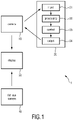
- Fig. 1 shows a schematic diagram of a system 1 and device 20 according to the present invention.
- the system comprises at least a camera 10 that can operate in a first monitoring mode and a second monitoring mode according to a control signal and a device 20 for generating and outputting a control signal to the camera.
- the device 20 obtains (e.g. receives or retrieves) video data acquired by the camera 10 and evaluates them.
- the device 20 comprises an input unit 21 for obtaining the video data from the camera.
- the input unit 21 may e.g. be a data interface for receiving the video data via a wired or wireless connection with the camera, e.g. via a WLAN or LAN connection.
- the device 20 further comprises an image processing unit 22, e.g. a processor or computer, for determining from the obtained video data if a particular person, e.g. a patient, is present alone in a first area monitored by the camera 10.
- an image processing unit 22 e.g. a processor or computer, for determining from the obtained video data if a particular person, e.g. a patient, is present alone in a first area monitored by the camera 10.
- the device 20 further comprises a control unit 23, e.g. a controller, processor or computer (e.g. the same processor or computer that implements the image processing unit 22) for generating a control signal for controlling the camera 10 to operate in a first monitoring mode or a second monitoring mode based on the determination by the image processing unit 22.
- a control unit 23 e.g. a controller, processor or computer (e.g. the same processor or computer that implements the image processing unit 22) for generating a control signal for controlling the camera 10 to operate in a first monitoring mode or a second monitoring mode based on the determination by the image processing unit 22.
- the device 20 further comprises an output unit 24 for outputting the control signal to the camera.
- the output unit 24 may e.g. be a data interface for transmitting the control signal via a wired or wireless connection with the camera, e.g. via a WLAN or LAN connection.
- the device 20 may be implemented in hard- and/or software.
- the device 20 may be implemented as appropriately programmed computer or processor.
- the device 20 may e.g. be a computer or a workstation or a mobile user device, such as a smartphone, laptop, tablet, smart watch.
- the device 20 may be implemented on a caregiver's smartphone so that the caregiver can always monitor the patient or gets new monitoring information if e.g. the monitoring mode changes.
- the device 20 may be implemented on a computer in a central monitoring room in which many patient rooms are centrally supervised.
- the system 1 may further comprise a display 30, e.g. a computer monitor or the display of a mobile user device, for displaying the video acquired by the camera 10. Still further, a fish eye camera 40 may be provided to always monitor the first area or an even larger area even if the camera 10 switches between different monitoring modes.
- a display 30 e.g. a computer monitor or the display of a mobile user device
- a fish eye camera 40 may be provided to always monitor the first area or an even larger area even if the camera 10 switches between different monitoring modes.
- Figs. 2 to 4 show different situations of a realistic scenario in which the present invention may be applied.
- a patient 2 is lying in a patient bed 3 in a hospital's patient room 4.
- the camera 10, e.g. a 3D PTZ camera, is mounted at a wall (or the ceiling) and is able to pan, tilt and rotate.
- the optional fish eye camera 40 is mounted in an upper corner of the room 4.
- the device 20 and the display 30 may be located in another room, e.g. a central monitoring room.
- the control signal generated by the device 20 controls the camera 10 to operate in the first monitoring mode or in the second monitoring mode.
- a first area 11 or a third area 13 is monitored in case the particular person is not alone in the first area.
- a second area 12 is monitored in case the particular person is alone in the first area. This shall be explained with reference to the situation illustrated in Figs. 2 to 4 .
- a second area 12 is monitored, which is substantially the area of the patient 2 itself and substantially includes the patient 2 or part of the patient 2 (e.g. the patient's face or upper part of the body).
- the patient 2 is not alone in the patient room 4 but another person 5, e.g. a caregiver or doctor or visitor, is present in the room 3 so that the camera 10 is controlled to operate in the first monitoring mode.
- the other person 5 is present in the area of the door 6.
- a first area 11 is thus monitored, which may be the maximum field of view of the camera 10.
- the first area 11 is almost the complete patient room 4 as far as it can be seen by the camera 10.
- FIG. 4 the patient 2 is again not alone in the patient room 4 but another person 7, e.g. a caregiver or doctor or visitor, is present in the room 3 so that the camera 10 is again controlled to operate in the first monitoring mode.
- the other person 7 is present in the area of the bed 3.
- a third area 13 is thus monitored, which may be region around the bed 3 so that in includes the patient 2 and the other person 7.
- the second area 12 is smaller than the first area 11 and substantially includes the particular person 2 and the third area 13 is larger than the second area 12 but smaller than the first area 11 and includes one or more persons 5, 7, other than the particular person 2, present in the first area 11.
- one or more settings (e.g. focus area and/or zoom level) of the 3D PTZ camera are automatically adapted based on the current activities in the room and a scene analysis to achieve optimal monitoring results.
- a flow chart of an exemplary embodiment of a monitoring method according to the present invention is shown in Fig. 5 . This exemplary embodiment is explained with reference to a similar scenario shown in Figs. 2 to 4 .
- a first step S10 the camera is rotated such that the ground plane is flat.
- Bed segmentation using a scene segmentation algorithm may be performed, and the image zoom may be adjusted to focus on the bed region.
- a second step S11 it is detected if the patient is in the bed based on a depth profile obtained from the video data. If the patient is not in the bed, the depth profile of the bed is (almost) flat. In an exemplary implementation the distribution (histogram) of the depth values in the bed region is checked. If the patient is not in the bed, the camera will be switched to the second (room) monitoring mode to check if the patient is seated in a chair.
- a third step S12 it is detected if the patient is in a chair. This can be done by checking the depth profile in a surrounding area that is close to the bed region. A chair usually corresponds to a segmented blob from the scene segmentation algorithm. If a chair with patient is not found, the camera will be switched to the second (room) monitoring mode.
- Motion estimation may be performed to capture more details.
- the camera will zoom in on areas with small subtle motion especially for the hand region (step S14). If no motion is detected in the zoomed in area for one minute, the camera will zoom out to have the complete bed area in view (step S13).
- Prioritization of the zoom in area may be performed. If motion is detected in more than one area in the image with partly subtle motion, it may be decided to zoom in based on priority of the area with subtle motion and only zoom in at the area with highest priority. Typical delirious behavior is mainly manifested by hand motions. Hence, zooming in to optimally detect the motion of the hands is advantageous.
- a person pose detector e.g. based on OpenPose detector
- OpenPose detector may be used to localize the different body parts, such as head, arms, hands and legs.
- Focusing on patient facial area may be performed (step S15). This enables the analysis of facial expressions, which may provide important cues about the patient's state, e.g. potential delirium, pain and/or stress.
- bed exit or entry may be detected (step S16) such that the camera will automatically be switched to the second (room) monitoring mode.
- step S17 other person(s) may be detected (step S17). It may e.g. be detected when another person, in addition to the patient, is entering room, in particular the camera view. If the patient is not alone in the monitored area, the camera may be switched to the second monitoring mode to learn about the context of the measurement. Depending on the position of the other person, the focus may be adjusted to a smaller region (third area) of the scene instead of the whole room (first area).
- an activity (motion) level measurement may be made (step S18). Based thereon the camera view may be zoomed and/or shifted to focus on the most intensive activities or interactions.
- a standard 3D PTZ camera is used that is mounted at the ceiling and facing downwards.
- a pre-calibration step may be performed to estimate the tilt angle of the camera (with respect to the ground plane, e.g. the floor of the room), and the camera is then mechanically rotated such that the ground plane is flat in the camera view.
- a correction of the video data is performed computationally such that the ground plane is arranged in horizontal direction.
- Fig. 6A shows a camera view of a camera mounted at the ceiling above a patient bed.
- Fig. 6B shows a depth view from this perspective.
- Fig. 7A shows a point cloud representation of the depth data shown in Fig. 6B .
- This point cloud representation can generally be constructed from a side view image and/or a related top view image. It may be assumed that from the original 3D point clouds (as shown in Fig. 7A in which the viewing angle is facing the end of the patient bed, where two persons are standing next to the bed) up to 0.5 meters (or any other reasonable value that may be set in advance or may be estimated for the particular view) above the farthest points constitute mostly ground pixels.
- RANSAC Random Sample Consensus
- the RANSAC based estimation represents a very robust solution due to its ability to handle outliers.
- the camera may be rotated such that the ground plane is on the X-Y plane (as shown in Fig. 7B ).
- the Z values of the new point cloud reflect the true height of the scene objects above the ground plane. It shall be noted that other methods instead of the RANSAC algorithm may be applied instead to achieve such a correction.
- To determine what to monitor in the room it is determined if there are other people present in the room or if the patient is alone in the room. In an embodiment this may be done as follows.
- a ROI (region of interest) detection algorithm may be applied to outline the patient area, as e.g. shown in Fig. 8A . This may e.g. be done using the method described in WO 2020/127014 A1 . From the depth profile of the patient area (referred to as second area herein), it is known if the patient is in bed or not. If yes, the following step may be carried out to decide if the patient is alone in the room.
- a motion map may be generated from the video data, e.g. based on frame differencing, H3DRS or optical flow. If the detected motion area (outside the patient area) is/are not adjacent to the patient area, it may be assumed that there are other people in the room but they are not physically interacting with the patient.
- the motion field (as e.g. shown in Fig. 8B and 8C ) has intersections with the patient area, the associated real depth values of these motion components may further be checked. Based on the above it can be derived if there exist interactions between the patient area and other people (such nurses, doctors, visitors, etc.).
- the camera may then be controlled to zoom out such that the persons interacting with the patient and the patient area are in the field of view, i.e. the camera is controlled to monitor a third area that is larger than the patient area.
- the detected other connected components e.g. a blob surrounding the bed area may further be checked in order to locate potential chair existence. This again can be confirmed by the shape and depth profile of the blob. If the patient is in the chair, the same logic as explained above for the situation in which the patient is in the bed may be followed.
- analytic features or modes for real-time monitoring may be applied. They can be manually chosen or triggered by events that are automatically detected.
- full-bed monitoring may be performed.
- the zoom level of the camera may be adjusted such that the bed area occupies most of the field-of-view (e.g. 80%).
- An example is shown in Fig. 8A . This operation can be used as default operation.
- in-bed motion focusing may be performed.
- the patient motion while lying on bed provides important hints for delirium detection, such as picking at bedsheets.
- By motion detection small motions of the patient can be captured and the camera can be zoomed in for better details. This is not only done for better visualization but also provides better (high-resolution) inputs for algorithms that are used for further analysis of these subtle motion.
- a method as e.g. described in US 2014/235969 A may be used.
- facial expression analysis may be performed. Facial expression is one important communication cue for ICU patients.
- an automatic face detection algorithm may be used such as described in Weon SH., Joo SI., Choi HI. (2014) Using Depth Information for Real-Time Face Detection. In: Stephanidis C. (eds) HCI International 2014 - Posters' Extended Abstracts. HCI 2014, Communications in Computer and Information Science, vol 434, Springer , to find the facial region.
- the PTZ camera can zoom in to this region.
- the images can be used for visual inspection or fed into an automatic facial expression analysis algorithm. This operation can be selected manually or triggered by facial motion in a similar way as described above.
- bed entry/exit detection may be performed.
- the bed boundary may be constantly monitored to detect any event of bed entry/exit. This can e.g. be achieved by checking the motion direction over the bed boundary, either from outside in or from inside out. If the bed entry/exit event is detected the camera may be controlled to zoom level to monitor the full room.
- a method as e.g. described in US 2019/228866 A1 or US 2019/192052 A1 may be used.
- entry/exit detection of another person may be performed. It may be detected when another person next to the patient is entering the image. Knowing this, the camera may adjust its zooming behavior accordingly.
- the camera may be combined with e.g. a fish eye camera so all activities in the room can be registered. Images of such an additional camera may be analysed for motion hot spots. It will provide this information for the analysis and will be used to return from patient monitoring mode to room monitoring mode (first monitoring mode).
- digital zoom may be used to focus on interested regions while using the original full resolution image for continuous full-room monitoring.
- the present invention provides the ability of camera-based ICU room monitoring, but may also be used for general ward, geriatric ward and other healthcare setting using camera monitoring. Further, it enables automatic characterization of ICU patient motion. Further options that are provided by the present invention include delirium detection, vital signs monitoring, decubitus management, and fall management.
- a computer program may be stored/distributed on a suitable non-transitory medium, such as an optical storage medium or a solid-state medium supplied together with or as part of other hardware, but may also be distributed in other forms, such as via the Internet or other wired or wireless telecommunication systems.
- a suitable non-transitory medium such as an optical storage medium or a solid-state medium supplied together with or as part of other hardware, but may also be distributed in other forms, such as via the Internet or other wired or wireless telecommunication systems.
Abstract
A device (20) and method for controlling a camera (10) are provided. The device comprises an input unit (21) configured to obtain video data from the camera; an image processing unit (22) configured to determine from the obtained video data if a particular person is present alone in a first area monitored by the camera; a control unit (23) configured to generate a control signal for controlling the camera to operate in a first monitoring mode or a second monitoring mode based on the determination by the image processing unit; and an output unit (24) configured to output the control signal to the camera.
Description
- The present invention relates to a device and method for controlling a camera, in particular a camera for monitoring a patient in a patient room of e.g. a hospital or rest home. The present invention relates further to a corresponding system.
- Increasingly, camera technology is being used in different wards in the hospital for remote and automatic monitoring. The camera is an unobtrusive sensor and gives a lot of information about the context of a certain measurement. In the intensive care unit (ICU), a camera can be of added value and can be used in applications as delirium monitoring, sleep monitoring, decubitus management, fall management, vital signs monitoring, etc.
- For these applications, different aspects need to be robustly detected including subtle motions. For example, delirious patients manifest typical motion with the hand such as picking at the bedsheets. To be able to detect these small motions it is important to have a good field of view on the moving object.
- There are different camera modalities such as RGB (color), infrared, or depth cameras, all having their advantages and disadvantages for the use in an ICU. The ICU environment is a dynamic environment with next to a lot of activity of staff and visitors also dynamic light conditions, position of the bed, etc. A depth camera has the advantage of being insensitive for light changes e.g. introduced by flashing monitoring lights, casting shadows, dark condition during the night.
- Most depth cameras have fixed focal length but there are already camera platforms that support adjustable focal length (zoom) and mechanical movements (pan, rotation/tilt). A 3D depth camera with PTZ (Pan-Tilt-Zoom) function is thereby made possible. A PTZ camera gives the opportunity to precisely zoom in on subtle motion enhancing the detectability and the output of the particular measurement e.g. delirium score.
- It is an object of the present invention to further exploit options to apply such camera for monitoring a person by a camera, e.g. a patient in an ICU, and controlling the camera to offer additional functions.
- In a first aspect of the present invention a device for controlling a camera is presented comprising:
- an input unit configured to obtain video data from the camera;
- an image processing unit configured to determine from the obtained video data if a particular person is present alone in a first area monitored by the camera;
- a control unit configured to generate a control signal for controlling the camera to operate in a first monitoring mode or a second monitoring mode based on the determination by the image processing unit, wherein the control signal is configured to control the camera to operate in the first monitoring mode in which the first area or a third area is monitored in case the particular person is not alone in the first area and to operate in the second monitoring mode in which a second area is monitored in case the particular person is alone in the first area, wherein the second area is smaller than the first area and substantially includes the particular person and the third area is larger than the second area but smaller than the first area and includes one or more persons, other than the particular person, present in the first area; and
- an output unit configured to output the control signal to the camera.
- In a further aspect of the present invention a system for monitoring an area is presented comprising:
- a camera configured to operate in a first monitoring mode and a second monitoring mode according to a control signal,
- a device as disclosed herein for generating and outputting a control signal to the camera.
- In yet further aspects of the present invention, there are provided a corresponding method, a computer program which comprises program code means for causing a computer to perform the steps of the method disclosed herein when said computer program is carried out on a computer as well as a non-transitory computer-readable recording medium that stores therein a computer program product, which, when executed by a processor, causes the method disclosed herein to be performed.
- Preferred embodiments of the invention are defined in the dependent claims. It shall be understood that the claimed method, system, computer program and medium have similar and/or identical preferred embodiments as the claimed system, in particular as defined in the dependent claims and as disclosed herein.
- The present invention is based on the idea to make use of a camera for monitoring an area, such as an ICU room, and to control the camera based on an evaluation of the video data acquired by the camera to operate in one of at least two different monitoring modes. Switching from one monitoring mode hereby involves adjusting one or more of the settings of the camera, such as changing the viewing angle, the focus area, the zoom factor, etc.
- Hereby, in the most general case, the monitoring modes are switched based on whether or not a particular person, e.g. a patient to be mainly monitored, is present in a first area, e.g. in the room that is viewed in the first monitoring mode (also called scene or room monitoring mode). If the particular person is alone in the first area (i.e. no other persons are present in the room), the camera is switched into the second monitoring mode (also called patient monitoring mode) in which e.g. only the particular person (i.e. the patient as lying in the bed or sitting in a chair) is monitored so that camera zooms in to the particular person. If, on the other hand, one or more other persons are present in the first area, the camera is switched into (or remains in) the first monitoring mode in which either complete first area or a third area (e.g. an area in which some or all of the other persons are located) is monitored. Thus, in an implementation of the present invention, one or more camera settings may be adjusted to best suit ongoing activities in a room.
- In a realistic scenario, the present invention may be useful to avoid false or unnecessary alarms. For instance, if the camera is used to detect if the patient is in risk to fall off the bed or to detect one or more vital signs (such as heart rate, respiration rate, oxygen saturation (SpO2), etc.) and thus is focussed on the patient and the bed, there may be situations in which an alarm is issued (e.g. on a central monitoring screen and/or caregiver's mobile device) if a patient moves to the edge of the bed so that he might fall off the bed or if a particular vital sign indicates a critical situation. If, however, it is known that another person (e.g. a nurse or caregiver) is present in the room as well, which information can be obtained if the camera is switched into the first monitoring mode as soon as it is detected that one or more other persons in addition to the patient, such an alarm becomes unnecessary and can be suppressed since the other person is already present in the room and can directly recognize the patient's critical situation and take appropriate action.
- Another scenario where detection of the presence of another person in the room makes sense is if the camera is used for detecting delirium or epileptic seizure. Furthermore, the camera may be switched into a mode where small motions of the patient are detected to enable the ability and reliability of motion detection and recognition of delirium or an epileptic seizure.
- In another embodiment in-bed motion focusing may be performed. The patient motion while lying on bed provides important hints for delirium detection, such as picking at bedsheets. By motion detection small motions of the patient can be captured and the camera can be zoomed in for better details. This is not only done for better visualization but also provides better (high-resolution) inputs for algorithms that are used for further analysis of these subtle motion. For detecting delirium from subtle motion a method as e.g. described in
US 2014/235969 A may be used. - In an embodiment the image processing unit is configured to determine from the obtained video data if the particular person is present alone in the first area by detecting activities in the first area and determining if the activities represent motion of one or more persons. Such an embodiment can be easily implemented and provides reliable results.
- In a particular embodiment the image processing unit is further configured to determine, in case one or more other persons are detected in the first area, if one or more of them is within or overlapping with or adjacent to the second area. Further, the control unit is configured to generate, in case one or more of the other persons is within or overlapping with or adjacent to the second area, a control signal for controlling the camera to operate in the first monitoring mode and to monitor the third area substantially including the particular person and the one or more of the other persons. Thus, if there are one or more persons close to the particular person, e.g. if there are one or more caregivers or relatives close to the patient, the area around the patient shall be monitored so that not only the patient but also the person(s) adjacent to the patient is (are) monitored to have a better understanding if and what happens to the patient.
- The control unit may further be configured to generate, in case none of the other persons is within or overlapping with or adjacent to the second area, a control signal for controlling the camera to operate in the second monitoring mode or to operate in the first monitoring mode and to monitor the first area. Hence, in the example of monitoring a patient room, if there are no persons adjacent to the patient, the camera shall either zoom on the patient or monitor the whole room.
- In another embodiment the image processing unit is configured to detect in the obtained video data a particular furniture, in particular a bed or chair (e.g. a patient bed in hospital's patient room or a relaxing chair in a rest home), to determine if the particular person is present on or at said furniture and to define the area substantially including the particular furniture on or at which the particular person is present as second area. For instance, the particular furniture may be detected and it may be determined if the particular person is present on or at said furniture based on depth information of said video data. Depth information may e.g. be obtained from a 3D or depth camera.
- The image processing unit is configured to correct obtained video data by correcting the viewing angle of the camera such that a ground plane is arranged is horizontal direction and to use the corrected video data for determining if a particular person is present alone in the first area. With such a correction it is easier to determine distances and detect spatial relationships of persons and things detected in the video data. Further, this helps to detect e.g. a particular furniture such as a patient bed.
- Rather than computing a correction of the video data, in another embodiment the control unit is configured to generate a control signal for controlling the camera to rotate such that a ground plane is arranged in horizontal direction.
- In another embodiment the image processing unit is configured to perform, in the second monitoring mode, one or more of a facial expression analysis of facial expressions of the particular person, a bed exit detection to detect if the particular person has exited or entered or is in risk to fall off the bed, a motion detection to detect specific motions of the particular person, a vital sign detection to detect one or more vital signs of the particular person, and an approach detection to detect if one or more other persons approach or leave the particular person. Thus, various options exist which may be used alternatively or in combination depending on user requirements or general needs or applications of the device and method of the present invention.
- The camera of the proposed system may be configured to pan and/or to tilt and/or to zoom under control of the control signal. For instance, a 3D pan-tilt-zoom (PTZ) camera may be used. The camera may be configured to be fixedly mounted in a room (e.g. on the ceiling or a wall) or to be movably positioned in a room (e.g. via a movable stand or tripod).
- Advantageously, the system may further comprise a fish eye camera configured to always monitor the first area or an even larger area. Thus, in addition to the above-mentioned camera which is controlled to monitor different areas, monitoring of the first area (e.g. a patient room from a particular view) or an even larger area (e.g. a wider view and thus a larger area of the patient room) is always possible in this way.
- These and other aspects of the invention will be apparent from and elucidated with reference to the embodiment(s) described hereinafter. In the following drawings:
-
Fig. 1 shows a schematic diagram of a system and device according to the present invention; -
Figs. 2 to 4 show different situations of a realistic scenario in which the present invention may be applied; -
Fig. 5 shows a flow chart of an exemplary embodiment of a monitoring method according to the present invention; -
Fig. 6A shows a camera view of a camera mounted at the ceiling above a patient bed; -
Fig. 6B shows a depth view from the same perspective as the camera view shown inFig. 6A ; -
Fig. 7A shows a camera view facing the end of the patient bed; -
Fig. 7B shows a corrected view after viewing angle correction; -
Fig. 8A shows an image of an identified patient area; -
Fig. 8B shows an image of the patient area and persons adjacent to the patient area; and -
Fig. 8C shows an image of only the persons adjacent to the patient area. -
Fig. 1 shows a schematic diagram of asystem 1 anddevice 20 according to the present invention. The system comprises at least acamera 10 that can operate in a first monitoring mode and a second monitoring mode according to a control signal and adevice 20 for generating and outputting a control signal to the camera. For this purpose, thedevice 20 obtains (e.g. receives or retrieves) video data acquired by thecamera 10 and evaluates them. - The
device 20 comprises aninput unit 21 for obtaining the video data from the camera. Theinput unit 21 may e.g. be a data interface for receiving the video data via a wired or wireless connection with the camera, e.g. via a WLAN or LAN connection. - The
device 20 further comprises animage processing unit 22, e.g. a processor or computer, for determining from the obtained video data if a particular person, e.g. a patient, is present alone in a first area monitored by thecamera 10. - The
device 20 further comprises acontrol unit 23, e.g. a controller, processor or computer (e.g. the same processor or computer that implements the image processing unit 22) for generating a control signal for controlling thecamera 10 to operate in a first monitoring mode or a second monitoring mode based on the determination by theimage processing unit 22. - The
device 20 further comprises anoutput unit 24 for outputting the control signal to the camera. Theoutput unit 24 may e.g. be a data interface for transmitting the control signal via a wired or wireless connection with the camera, e.g. via a WLAN or LAN connection. - The
device 20 may be implemented in hard- and/or software. For instance, thedevice 20 may be implemented as appropriately programmed computer or processor. Depending on the application, thedevice 20 may e.g. be a computer or a workstation or a mobile user device, such as a smartphone, laptop, tablet, smart watch. For instance, in an application in a hospital or rest home, thedevice 20 may be implemented on a caregiver's smartphone so that the caregiver can always monitor the patient or gets new monitoring information if e.g. the monitoring mode changes. In another application, thedevice 20 may be implemented on a computer in a central monitoring room in which many patient rooms are centrally supervised. - The
system 1 may further comprise adisplay 30, e.g. a computer monitor or the display of a mobile user device, for displaying the video acquired by thecamera 10. Still further, afish eye camera 40 may be provided to always monitor the first area or an even larger area even if thecamera 10 switches between different monitoring modes. -
Figs. 2 to 4 show different situations of a realistic scenario in which the present invention may be applied. In this scenario, a patient 2 is lying in apatient bed 3 in a hospital'spatient room 4. Thecamera 10, e.g. a 3D PTZ camera, is mounted at a wall (or the ceiling) and is able to pan, tilt and rotate. The optionalfish eye camera 40 is mounted in an upper corner of theroom 4. Thedevice 20 and thedisplay 30 may be located in another room, e.g. a central monitoring room. - The control signal generated by the
device 20 controls thecamera 10 to operate in the first monitoring mode or in the second monitoring mode. In the first monitoring mode afirst area 11 or athird area 13 is monitored in case the particular person is not alone in the first area. In the second monitoring mode asecond area 12 is monitored in case the particular person is alone in the first area. This shall be explained with reference to the situation illustrated inFigs. 2 to 4 . - In the situation shown in
Fig. 2 the patient 2 is alone in the patient room 4 (e.g. an ICU room) so that thecamera 10 is controlled to operate in the second monitoring mode. In this case asecond area 12 is monitored, which is substantially the area of the patient 2 itself and substantially includes the patient 2 or part of the patient 2 (e.g. the patient's face or upper part of the body). - In the situation shown in
Fig. 3 the patient 2 is not alone in thepatient room 4 but another person 5, e.g. a caregiver or doctor or visitor, is present in theroom 3 so that thecamera 10 is controlled to operate in the first monitoring mode. In this situation the other person 5 is present in the area of thedoor 6. Afirst area 11 is thus monitored, which may be the maximum field of view of thecamera 10. In the scenario shown inFig. 3 thefirst area 11 is almost thecomplete patient room 4 as far as it can be seen by thecamera 10. - In the situation shown in
Fig. 4 the patient 2 is again not alone in thepatient room 4 but another person 7, e.g. a caregiver or doctor or visitor, is present in theroom 3 so that thecamera 10 is again controlled to operate in the first monitoring mode. In this situation the other person 7 is present in the area of thebed 3. Athird area 13 is thus monitored, which may be region around thebed 3 so that in includes the patient 2 and the other person 7. - Hence, as illustrated in the situations shown in
Figs. 2 to 4 , thesecond area 12 is smaller than thefirst area 11 and substantially includes the particular person 2 and thethird area 13 is larger than thesecond area 12 but smaller than thefirst area 11 and includes one or more persons 5, 7, other than the particular person 2, present in thefirst area 11. - Thus, according to the present invention one or more settings (e.g. focus area and/or zoom level) of the 3D PTZ camera are automatically adapted based on the current activities in the room and a scene analysis to achieve optimal monitoring results.
- In the first monitoring mode (also called patient monitoring mode) a plurality of options exist. A flow chart of an exemplary embodiment of a monitoring method according to the present invention is shown in
Fig. 5 . This exemplary embodiment is explained with reference to a similar scenario shown inFigs. 2 to 4 . - In a first step S10 the camera is rotated such that the ground plane is flat. Bed segmentation using a scene segmentation algorithm may be performed, and the image zoom may be adjusted to focus on the bed region.
- In a second step S11 it is detected if the patient is in the bed based on a depth profile obtained from the video data. If the patient is not in the bed, the depth profile of the bed is (almost) flat. In an exemplary implementation the distribution (histogram) of the depth values in the bed region is checked. If the patient is not in the bed, the camera will be switched to the second (room) monitoring mode to check if the patient is seated in a chair.
- In a third step S12 it is detected if the patient is in a chair. This can be done by checking the depth profile in a surrounding area that is close to the bed region. A chair usually corresponds to a segmented blob from the scene segmentation algorithm. If a chair with patient is not found, the camera will be switched to the second (room) monitoring mode.
- If the patient is either in the bed or the chair, various options exist for further monitoring. Motion estimation may be performed to capture more details. The camera will zoom in on areas with small subtle motion especially for the hand region (step S14). If no motion is detected in the zoomed in area for one minute, the camera will zoom out to have the complete bed area in view (step S13).
- Prioritization of the zoom in area may be performed. If motion is detected in more than one area in the image with partly subtle motion, it may be decided to zoom in based on priority of the area with subtle motion and only zoom in at the area with highest priority. Typical delirious behavior is mainly manifested by hand motions. Hence, zooming in to optimally detect the motion of the hands is advantageous. A person pose detector (e.g. based on OpenPose detector) may be used to localize the different body parts, such as head, arms, hands and legs.
- Focusing on patient facial area may be performed (step S15). This enables the analysis of facial expressions, which may provide important cues about the patient's state, e.g. potential delirium, pain and/or stress.
- As another option bed exit or entry may be detected (step S16) such that the camera will automatically be switched to the second (room) monitoring mode.
- As another option other person(s) may be detected (step S17). It may e.g. be detected when another person, in addition to the patient, is entering room, in particular the camera view. If the patient is not alone in the monitored area, the camera may be switched to the second monitoring mode to learn about the context of the measurement. Depending on the position of the other person, the focus may be adjusted to a smaller region (third area) of the scene instead of the whole room (first area).
- In the second monitoring mode, if the patient is neither in the bed nor in the chair, an activity (motion) level measurement may be made (step S18). Based thereon the camera view may be zoomed and/or shifted to focus on the most intensive activities or interactions.
- In an embodiment a standard 3D PTZ camera is used that is mounted at the ceiling and facing downwards. A pre-calibration step may be performed to estimate the tilt angle of the camera (with respect to the ground plane, e.g. the floor of the room), and the camera is then mechanically rotated such that the ground plane is flat in the camera view. In another embodiment, a correction of the video data is performed computationally such that the ground plane is arranged in horizontal direction.
Fig. 6A shows a camera view of a camera mounted at the ceiling above a patient bed.Fig. 6B shows a depth view from this perspective. - In another embodiment, for convenience of the further analysis, the camera's viewing angle may be corrected such that the ground plane is always horizontal on the X-Y plane.
Fig. 7A shows a point cloud representation of the depth data shown inFig. 6B . This point cloud representation can generally be constructed from a side view image and/or a related top view image. It may be assumed that from the original 3D point clouds (as shown inFig. 7A in which the viewing angle is facing the end of the patient bed, where two persons are standing next to the bed) up to 0.5 meters (or any other reasonable value that may be set in advance or may be estimated for the particular view) above the farthest points constitute mostly ground pixels. These selected pixels are used to fit a 3D ground plane with a robust method, such as a technique called RANSAC (RANdom Sample Consensus). The RANSAC based estimation represents a very robust solution due to its ability to handle outliers. Based on the estimated plane parameters, the camera may be rotated such that the ground plane is on the X-Y plane (as shown inFig. 7B ). The Z values of the new point cloud reflect the true height of the scene objects above the ground plane. It shall be noted that other methods instead of the RANSAC algorithm may be applied instead to achieve such a correction. - To determine what to monitor in the room it is determined if there are other people present in the room or if the patient is alone in the room. In an embodiment this may be done as follows.
- In a first step a ROI (region of interest) detection algorithm may be applied to outline the patient area, as e.g. shown in
Fig. 8A . This may e.g. be done using the method described inWO 2020/127014 A1 . From the depth profile of the patient area (referred to as second area herein), it is known if the patient is in bed or not. If yes, the following step may be carried out to decide if the patient is alone in the room. - A motion map may be generated from the video data, e.g. based on frame differencing, H3DRS or optical flow. If the detected motion area (outside the patient area) is/are not adjacent to the patient area, it may be assumed that there are other people in the room but they are not physically interacting with the patient.
- If the motion field (as e.g. shown in
Fig. 8B and 8C ) has intersections with the patient area, the associated real depth values of these motion components may further be checked. Based on the above it can be derived if there exist interactions between the patient area and other people (such nurses, doctors, visitors, etc.). The camera may then be controlled to zoom out such that the persons interacting with the patient and the patient area are in the field of view, i.e. the camera is controlled to monitor a third area that is larger than the patient area. - If the motion is outside the patient area, the may be controlled to switch to the patient monitoring mode (second monitoring mode) and to zoom in to the patient area.
- If there is no patient detected in the bed area the detected other connected components (e.g. a blob) surrounding the bed area may further be checked in order to locate potential chair existence. This again can be confirmed by the shape and depth profile of the blob. If the patient is in the chair, the same logic as explained above for the situation in which the patient is in the bed may be followed.
- For detecting activities or motion from video data many different algorithms are generally known, such as algorithms using background subtraction (determining the difference between a current video frame and a reference frame or the preceding video frame) or algorithms using models based on optical flow. For determining if activities represent motion of a person known algorithms can be applied as well, such as algorithms evaluation texture, shape, motion pattern, etc. of image regions showing activities. Various algorithms are e.g. described in Paul, M., Haque, S.M.E. & Chakraborty, S. Human detection in surveillance videos and its applications - a review. EURASIP J. Adv. Signal Process. 2013, 176 (2013). To distinguish if there are different persons can e.g. be accomplished by detecting if regions with activities are clearly separated.
- If the patient is alone in the room, one or more of the following analytic features or modes for real-time monitoring may be applied. They can be manually chosen or triggered by events that are automatically detected.
- In an embodiment full-bed monitoring may be performed. In this operation, the zoom level of the camera may be adjusted such that the bed area occupies most of the field-of-view (e.g. 80%). An example is shown in
Fig. 8A . This operation can be used as default operation. - In another embodiment in-bed motion focusing may be performed. The patient motion while lying on bed provides important hints for delirium detection, such as picking at bedsheets. By motion detection small motions of the patient can be captured and the camera can be zoomed in for better details. This is not only done for better visualization but also provides better (high-resolution) inputs for algorithms that are used for further analysis of these subtle motion. For detecting delirium from subtle motion a method as e.g. described in
US 2014/235969 A may be used. - In another embodiment facial expression analysis may be performed. Facial expression is one important communication cue for ICU patients. For this operation, an automatic face detection algorithm may be used such as described in Weon SH., Joo SI., Choi HI. (2014) Using Depth Information for Real-Time Face Detection. In: Stephanidis C. (eds) HCI International 2014 - Posters' Extended Abstracts. HCI 2014, Communications in Computer and Information Science, vol 434, Springer, to find the facial region. The PTZ camera can zoom in to this region. The images can be used for visual inspection or fed into an automatic facial expression analysis algorithm. This operation can be selected manually or triggered by facial motion in a similar way as described above.
- In another embodiment bed entry/exit detection may be performed. The bed boundary may be constantly monitored to detect any event of bed entry/exit. This can e.g. be achieved by checking the motion direction over the bed boundary, either from outside in or from inside out. If the bed entry/exit event is detected the camera may be controlled to zoom level to monitor the full room. For detecting bed entry/exit a method as e.g. described in
US 2019/228866 A1 orUS 2019/192052 A1 may be used. - In another embodiment entry/exit detection of another person (e.g. nurse or visitor) may be performed. It may be detected when another person next to the patient is entering the image. Knowing this, the camera may adjust its zooming behavior accordingly.
- For a continuous overview of all activities in the room the camera may be combined with e.g. a fish eye camera so all activities in the room can be registered. Images of such an additional camera may be analysed for motion hot spots. It will provide this information for the analysis and will be used to return from patient monitoring mode to room monitoring mode (first monitoring mode).
- For a single PTZ camera, digital zoom may be used to focus on interested regions while using the original full resolution image for continuous full-room monitoring.
- The present invention provides the ability of camera-based ICU room monitoring, but may also be used for general ward, geriatric ward and other healthcare setting using camera monitoring. Further, it enables automatic characterization of ICU patient motion. Further options that are provided by the present invention include delirium detection, vital signs monitoring, decubitus management, and fall management.
- While the invention has been illustrated and described in detail in the drawings and foregoing description, such illustration and description are to be considered illustrative or exemplary and not restrictive; the invention is not limited to the disclosed embodiments. Other variations to the disclosed embodiments can be understood and effected by those skilled in the art in practicing the claimed invention, from a study of the drawings, the disclosure, and the appended claims.
- In the claims, the word "comprising" does not exclude other elements or steps, and the indefinite article "a" or "an" does not exclude a plurality. A single element or other unit may fulfill the functions of several items recited in the claims. The mere fact that certain measures are recited in mutually different dependent claims does not indicate that a combination of these measures cannot be used to advantage.
- A computer program may be stored/distributed on a suitable non-transitory medium, such as an optical storage medium or a solid-state medium supplied together with or as part of other hardware, but may also be distributed in other forms, such as via the Internet or other wired or wireless telecommunication systems.
- Any reference signs in the claims should not be construed as limiting the scope.
Claims (15)
- Device (20) for controlling a camera (10), the device comprising:- an input unit (21) configured to obtain video data from the camera;- an image processing unit (22) configured to determine from the obtained video data if a particular person is present alone in a first area monitored by the camera;- a control unit (23) configured to generate a control signal for controlling the camera to operate in a first monitoring mode or a second monitoring mode based on the determination by the image processing unit, wherein the control signal is configured to control the camera to operate in the first monitoring mode in which the first area or a third area is monitored in case the particular person is not alone in the first area and to operate in the second monitoring mode in which a second area is monitored in case the particular person is alone in the first area, wherein the second area is smaller than the first area and substantially includes the particular person and the third area is larger than the second area but smaller than the first area and includes one or more persons, other than the particular person, present in the first area; and- an output unit (24) configured to output the control signal to the camera.
- Device as claimed in claim 1,
wherein the image processing unit (22) is configured to determine from the obtained video data if the particular person is present alone in the first area by detecting activities in the first area and determining if the activities represent motion of one or more persons. - Device as claimed in claim 2,
wherein the image processing unit (22) is configured to determine, in case one or more other persons are detected in the first area, if one or more of them is within or overlapping with or adjacent to the second area, and
wherein the control unit (23) is configured to generate, in case one or more of the other persons is within or overlapping with or adjacent to the second area, a control signal for controlling the camera to operate in the first monitoring mode and to monitor the third area substantially including the particular person and the one or more of the other persons. - Device as claimed in claim 3,
wherein the control unit (23) is configured to generate, in case none of the other persons is within or overlapping with or adjacent to the second area, a control signal for controlling the camera to operate in the second monitoring mode or to operate in the first monitoring mode and to monitor the first area. - Device as claimed in any one of the preceding claims,
wherein the image processing unit (22) is configured to detect in the obtained video data a particular furniture, in particular a bed or chair, to determine if the particular person is present on or at said furniture and to define the area substantially including the particular furniture on or at which the particular person is present as second area. - Device as claimed in claim 5,
wherein the image processing unit (22) is configured to detect the particular furniture and determine if the particular person is present on or at said furniture based on depth information of said video data. - Device as claimed in any one of the preceding claims,
wherein the image processing unit (22) is configured to correct obtained video data by correcting the viewing angle of the camera such that a ground plane is arranged in horizontal direction and to use the corrected video data for determining if a particular person is present alone in the first area. - Device as claimed in any one of the preceding claims,
wherein the control unit (23) is configured to generate a control signal for controlling the camera to rotate such that a ground plane is arranged in horizontal direction. - Device as claimed in any one of the preceding claims,
wherein the image processing unit (22) is configured to perform, in the second monitoring mode, one or more of a facial expression analysis of facial expressions of the particular person, a bed exit detection to detect if the particular person has exited or entered or is in risk to fall off the bed, a motion detection to detect specific motions of the particular person, a vital sign detection to detect one or more vital signs of the particular person, and an approach detection to detect if one or more other persons approach or leave the particular person. - System for monitoring an area, the system comprising:- a camera (10) configured to operate in a first monitoring mode and a second monitoring mode according to a control signal,- a device (20) as claimed in any one of claims 1 to 9 for generating and outputting a control signal to the camera.
- System as claimed in claim 10,
wherein the camera (10) is configured to pan and/or to tilt and/or to zoom under control of the control signal, in particular a 3D pan-tilt-zoom camera. - System as claimed in claim 10 or 11,
wherein the camera (10) is configured to be fixedly mounted in a room or to be movably positioned in a room. - System as claimed in claim 10, 11 or 12,
further comprising a fish eye camera (40) configured to always monitor the first area or an even larger area. - Method for controlling a camera (10), the method comprising:- obtaining video data from the camera;- determining from the obtained video data if a particular person is present alone in a first area monitored by the camera;- generating a control signal for controlling the camera to operate in a first monitoring mode or a second monitoring mode based on the determination by the image processing unit, wherein the control signal is configured to control the camera to operate in the first monitoring mode in which the first area or a third area is monitored in case the particular person is not alone in the first area and to operate in the second monitoring mode in which a second area is monitored in case the particular person is alone in the first area, wherein the second area is smaller than the first area and substantially includes the particular person and the third area is larger than the second area but smaller than the first area and includes one or more persons, other than the particular person, present in the first area; and- outputting the control signal to the camera.
- Computer program comprising program code means for causing a computer to carry out the steps of the method as claimed in claim 14 when said computer program is carried out on the computer.
Priority Applications (6)
| Application Number | Priority Date | Filing Date | Title |
|---|---|---|---|
| EP20208465.3A EP4002365A1 (en) | 2020-11-18 | 2020-11-18 | Device and method for controlling a camera |
| PCT/EP2021/081177 WO2022106269A1 (en) | 2020-11-18 | 2021-11-10 | Device and method for controlling a camera |
| US18/036,188 US20230412919A1 (en) | 2020-11-18 | 2021-11-10 | Device and method for controlling a camera |
| EP21810331.5A EP4248442A1 (en) | 2020-11-18 | 2021-11-10 | Device and method for controlling a camera |
| JP2023527682A JP2023548886A (en) | 2020-11-18 | 2021-11-10 | Apparatus and method for controlling a camera |
| CN202180077796.9A CN116457882A (en) | 2020-11-18 | 2021-11-10 | Apparatus and method for controlling camera |
Applications Claiming Priority (1)
| Application Number | Priority Date | Filing Date | Title |
|---|---|---|---|
| EP20208465.3A EP4002365A1 (en) | 2020-11-18 | 2020-11-18 | Device and method for controlling a camera |
Publications (1)
| Publication Number | Publication Date |
|---|---|
| EP4002365A1 true EP4002365A1 (en) | 2022-05-25 |
Family
ID=73476046
Family Applications (2)
| Application Number | Title | Priority Date | Filing Date |
|---|---|---|---|
| EP20208465.3A Withdrawn EP4002365A1 (en) | 2020-11-18 | 2020-11-18 | Device and method for controlling a camera |
| EP21810331.5A Pending EP4248442A1 (en) | 2020-11-18 | 2021-11-10 | Device and method for controlling a camera |
Family Applications After (1)
| Application Number | Title | Priority Date | Filing Date |
|---|---|---|---|
| EP21810331.5A Pending EP4248442A1 (en) | 2020-11-18 | 2021-11-10 | Device and method for controlling a camera |
Country Status (5)
| Country | Link |
|---|---|
| US (1) | US20230412919A1 (en) |
| EP (2) | EP4002365A1 (en) |
| JP (1) | JP2023548886A (en) |
| CN (1) | CN116457882A (en) |
| WO (1) | WO2022106269A1 (en) |
Families Citing this family (1)
| Publication number | Priority date | Publication date | Assignee | Title |
|---|---|---|---|---|
| JP2023035448A (en) * | 2021-09-01 | 2023-03-13 | パナソニックIpマネジメント株式会社 | Surveillance device, surveillance system, and surveillance method |
Citations (8)
| Publication number | Priority date | Publication date | Assignee | Title |
|---|---|---|---|---|
| US20100245532A1 (en) * | 2009-03-26 | 2010-09-30 | Kurtz Andrew F | Automated videography based communications |
| US20140235969A1 (en) | 2011-10-07 | 2014-08-21 | Koninklijke Philips N.V. | Monitoring system for monitoring a patient and detecting delirium of the patient |
| WO2018083074A1 (en) * | 2016-11-03 | 2018-05-11 | Koninklijke Philips N.V. | Automatic pan-tilt-zoom adjustment to improve vital sign acquisition |
| US20190192052A1 (en) | 2016-08-24 | 2019-06-27 | Koninklijke Philips N.V. | Device, system and method for patient monitoring to predict and prevent bed falls |
| US20190228866A1 (en) | 2016-08-24 | 2019-07-25 | Koninklijke Philips N.V. | Device, system and method for patient monitoring to predict and prevent bed falls |
| US20200196913A1 (en) * | 2017-07-11 | 2020-06-25 | Drägerwerk AG & Co. KGaA | Method, device and computer program for capturing optical image data of patient surroundings and for identifying a patient check-up |
| WO2020127014A1 (en) | 2018-12-17 | 2020-06-25 | Koninklijke Philips N.V. | Device, system and method for object recognition |
| US20200267321A1 (en) * | 2019-02-20 | 2020-08-20 | Canon Kabushiki Kaisha | Method, system and apparatus for capturing an image |
-
2020
- 2020-11-18 EP EP20208465.3A patent/EP4002365A1/en not_active Withdrawn
-
2021
- 2021-11-10 WO PCT/EP2021/081177 patent/WO2022106269A1/en active Application Filing
- 2021-11-10 JP JP2023527682A patent/JP2023548886A/en active Pending
- 2021-11-10 US US18/036,188 patent/US20230412919A1/en active Pending
- 2021-11-10 EP EP21810331.5A patent/EP4248442A1/en active Pending
- 2021-11-10 CN CN202180077796.9A patent/CN116457882A/en active Pending
Patent Citations (8)
| Publication number | Priority date | Publication date | Assignee | Title |
|---|---|---|---|---|
| US20100245532A1 (en) * | 2009-03-26 | 2010-09-30 | Kurtz Andrew F | Automated videography based communications |
| US20140235969A1 (en) | 2011-10-07 | 2014-08-21 | Koninklijke Philips N.V. | Monitoring system for monitoring a patient and detecting delirium of the patient |
| US20190192052A1 (en) | 2016-08-24 | 2019-06-27 | Koninklijke Philips N.V. | Device, system and method for patient monitoring to predict and prevent bed falls |
| US20190228866A1 (en) | 2016-08-24 | 2019-07-25 | Koninklijke Philips N.V. | Device, system and method for patient monitoring to predict and prevent bed falls |
| WO2018083074A1 (en) * | 2016-11-03 | 2018-05-11 | Koninklijke Philips N.V. | Automatic pan-tilt-zoom adjustment to improve vital sign acquisition |
| US20200196913A1 (en) * | 2017-07-11 | 2020-06-25 | Drägerwerk AG & Co. KGaA | Method, device and computer program for capturing optical image data of patient surroundings and for identifying a patient check-up |
| WO2020127014A1 (en) | 2018-12-17 | 2020-06-25 | Koninklijke Philips N.V. | Device, system and method for object recognition |
| US20200267321A1 (en) * | 2019-02-20 | 2020-08-20 | Canon Kabushiki Kaisha | Method, system and apparatus for capturing an image |
Non-Patent Citations (4)
Also Published As
| Publication number | Publication date |
|---|---|
| CN116457882A (en) | 2023-07-18 |
| JP2023548886A (en) | 2023-11-21 |
| EP4248442A1 (en) | 2023-09-27 |
| US20230412919A1 (en) | 2023-12-21 |
| WO2022106269A1 (en) | 2022-05-27 |
Similar Documents
| Publication | Publication Date | Title |
|---|---|---|
| JP6115335B2 (en) | Information processing apparatus, information processing method, and program | |
| JP6137425B2 (en) | Image processing system, image processing apparatus, image processing method, and image processing program | |
| JP5715132B2 (en) | Method and system for image analysis | |
| US20160142680A1 (en) | Image processing apparatus, image processing method, and storage medium | |
| US20190313948A1 (en) | Monitoring assistance system, control method thereof, and program | |
| JP6119938B2 (en) | Image processing system, image processing apparatus, image processing method, and image processing program | |
| US20230412919A1 (en) | Device and method for controlling a camera | |
| WO2016199504A1 (en) | Behavior detection device, behavior detection method, and monitored-person monitoring device | |
| US20190012546A1 (en) | Occupancy detection | |
| JP6729510B2 (en) | Monitoring support system and control method thereof | |
| JP7243725B2 (en) | Target object detection program and target object detection device | |
| Inoue et al. | Vision-based bed detection for hospital patient monitoring system | |
| EP3361464A1 (en) | Person monitoring device and method, and person monitoring system | |
| JP7347577B2 (en) | Image processing system, image processing program, and image processing method | |
| US20190318600A1 (en) | Monitoring assistance system, control method thereof, and program | |
| JP6645503B2 (en) | Image analysis device, image analysis method, and image analysis program | |
| US20210287518A1 (en) | Information processing apparatus, information processing system, method of providing information, and non-transitory recording medium | |
| JP6115693B1 (en) | Object detection apparatus, object detection method, and monitored person monitoring apparatus | |
| EP4176809A1 (en) | Device, system and method for monitoring a subject | |
| JP6729512B2 (en) | Monitoring support system and control method thereof | |
| WO2020008995A1 (en) | Image recognition program, image recognition device, learning program, and learning device | |
| JP2023075559A (en) | Image processing device, image processing system, image processing method and image processing program | |
| JP2021033379A (en) | Image processing system, image processing program, and image processing method | |
| CN111723629A (en) | Attitude monitoring method and computing device and system thereof | |
| JP2017045423A (en) | Image processing apparatus, image processing method, image processing system, and program |
Legal Events
| Date | Code | Title | Description |
|---|---|---|---|
| PUAI | Public reference made under article 153(3) epc to a published international application that has entered the european phase |
Free format text: ORIGINAL CODE: 0009012 |
|
| STAA | Information on the status of an ep patent application or granted ep patent |
Free format text: STATUS: THE APPLICATION HAS BEEN PUBLISHED |
|
| AK | Designated contracting states |
Kind code of ref document: A1 Designated state(s): AL AT BE BG CH CY CZ DE DK EE ES FI FR GB GR HR HU IE IS IT LI LT LU LV MC MK MT NL NO PL PT RO RS SE SI SK SM TR |
|
| STAA | Information on the status of an ep patent application or granted ep patent |
Free format text: STATUS: THE APPLICATION IS DEEMED TO BE WITHDRAWN |
|
| 18D | Application deemed to be withdrawn |
Effective date: 20221126 |