EP4002188A1 - Vehicle interior low noise optimization design method, and system - Google Patents
Vehicle interior low noise optimization design method, and system Download PDFInfo
- Publication number
- EP4002188A1 EP4002188A1 EP20934896.0A EP20934896A EP4002188A1 EP 4002188 A1 EP4002188 A1 EP 4002188A1 EP 20934896 A EP20934896 A EP 20934896A EP 4002188 A1 EP4002188 A1 EP 4002188A1
- Authority
- EP
- European Patent Office
- Prior art keywords
- vehicle
- sound
- total cost
- noise reduction
- sound source
- Prior art date
- Legal status (The legal status is an assumption and is not a legal conclusion. Google has not performed a legal analysis and makes no representation as to the accuracy of the status listed.)
- Pending
Links
Images


Classifications
-
- G—PHYSICS
- G06—COMPUTING OR CALCULATING; COUNTING
- G06F—ELECTRIC DIGITAL DATA PROCESSING
- G06F30/00—Computer-aided design [CAD]
- G06F30/10—Geometric CAD
- G06F30/15—Vehicle, aircraft or watercraft design
-
- G—PHYSICS
- G06—COMPUTING OR CALCULATING; COUNTING
- G06F—ELECTRIC DIGITAL DATA PROCESSING
- G06F30/00—Computer-aided design [CAD]
- G06F30/20—Design optimisation, verification or simulation
-
- G—PHYSICS
- G06—COMPUTING OR CALCULATING; COUNTING
- G06F—ELECTRIC DIGITAL DATA PROCESSING
- G06F2111/00—Details relating to CAD techniques
- G06F2111/04—Constraint-based CAD
-
- G—PHYSICS
- G06—COMPUTING OR CALCULATING; COUNTING
- G06F—ELECTRIC DIGITAL DATA PROCESSING
- G06F2119/00—Details relating to the type or aim of the analysis or the optimisation
- G06F2119/10—Noise analysis or noise optimisation
-
- Y—GENERAL TAGGING OF NEW TECHNOLOGICAL DEVELOPMENTS; GENERAL TAGGING OF CROSS-SECTIONAL TECHNOLOGIES SPANNING OVER SEVERAL SECTIONS OF THE IPC; TECHNICAL SUBJECTS COVERED BY FORMER USPC CROSS-REFERENCE ART COLLECTIONS [XRACs] AND DIGESTS
- Y02—TECHNOLOGIES OR APPLICATIONS FOR MITIGATION OR ADAPTATION AGAINST CLIMATE CHANGE
- Y02T—CLIMATE CHANGE MITIGATION TECHNOLOGIES RELATED TO TRANSPORTATION
- Y02T90/00—Enabling technologies or technologies with a potential or indirect contribution to GHG emissions mitigation
Definitions
- the present disclosure relates to the technical field of acoustic simulation, and in particular to a method and a system for optimizing and designing low in-vehicle noise.
- the noise of a rail transit vehicle usually includes off-vehicle noise and in-vehicle noise.
- an experienced acoustic system engineer In a process of controlling the in-vehicle noise by the numerical simulation analysis method, an experienced acoustic system engineer usually estimates a sound transmission loss required for each part of a body structure and sound source emitted from each device based on a target value of the in-vehicle noise in a vehicle design stage, and guides a low noise design for the vehicle based on the estimated value, thereby achieving the purpose of optimizing the in-vehicle noise.
- the numerical simulation analysis method significantly depends on subjective experience of the acoustic system engineer, and thus has problems of strong subjectivity and being prone to deviation.
- a method and a system for optimizing and designing low in-vehicle noise is provided according embodiments of the present disclosure, in order to solve the problems of long period, high cost, strong subjectivity, and being prone to deviation existing in the conventional solution for optimizing the in-vehicle noise.
- a method for optimizing and designing low in-vehicle noise includes:
- a process of performing the noise prediction based on the in-vehicle noise simulation-prediction-analysis model iteratively with starting with the input of the initial sound transmission losses and the initial sound powers and being under the constraint on a total cost for in-vehicle noise reduction includes:
- a process of performing calculation under the constraint on a total cost for in-vehicle noise reduction and based on the multivariate non-linear programming theory, to obtain the minimum total cost for in-vehicle noise reduction, the increment ⁇ TL i of the sound transmission loss of each of the different regions under the minimum total cost for in-vehicle noise reduction, and the decrement ⁇ L w of the sound power of each of the sound source devices under the minimum total cost for in-vehicle noise reduction includes:
- the sound transmission losses of the different regions include a sound transmission loss of any one or more of following regions of the vehicle: a floor, a side wall, a roof, an end wall, a passenger compartment side door, a driver's cab door, a window, a windshield, and a front end of the driver's cab.
- the sound powers of the sound source devices include a sound power of any one or more of a wheel and rail, an air conditioner, a traction converter, an auxiliary converter, a traction motor, an air compressor, and a gear box.
- a system for optimizing and designing low in-vehicle noise includes:
- the output unit that performs the noise prediction based on the in-vehicle noise simulation-prediction-analysis model iteratively with starting with the input of the initial sound transmission losses and the initial sound powers and being under the constraint on a total cost for in-vehicle noise reduction includes:
- the calculating module includes:
- a noise prediction is performed iteratively based on the in-vehicle noise simulation-prediction-analysis model, which guarantees to obtain a predicted noise value L psi that has no deviation and satisfies a minimum total cost for in-vehicle noise reduction, so that the method for optimizing and designing low in-vehicle noise has a short period, low cost and is not prone to deviation.
- the method does not require any subjective experience from a designer for vehicle design, and thereby has no subjectivity.
- the existing methods for optimizing and designing in-vehicle noise has problems of long period, high cost, strong subjectivity, and being prone to deviation.
- a method and a system for optimizing and designing low in-vehicle noise which perform noise prediction based on an in-vehicle noise simulation-prediction-analysis model iteratively to obtain a predicted noise value L psi that has no deviation and satisfies a minimum total cost for in-vehicle noise reduction, so as to achieve an objective that the method for optimizing and designing low in-vehicle noise has a short period, low cost and is not prone to deviation.
- the method does not require any subjective experience from a designer for vehicle design, and thereby has no subjectivity.
- the present disclosure solves the problems of long period, high cost, strong subjectivity and easy deviation in the existing solution for optimizing in-vehicle noise. Specific implementations are described in the following embodiments.
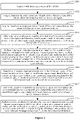
- Figure 1 is a schematic flow chart of a method for optimizing and designing low in-vehicle noise according to an embodiment of the present disclosure. As shown in Figure 1 , the method includes steps S101 to S104 as follows.
- step S101 acquire sound source distribution characteristics corresponding to different regions of a to-be-designed vehicle and sound source devices respectively, and establish an in-vehicle noise simulation-prediction-analysis model based on the sound source distribution characteristics.
- step S101 the in-vehicle noise simulation-prediction-analysis model is established based on a statistical energy analysis theory and the sound source distribution characteristics corresponding to the different regions of the to-be-designed vehicle and the sound source devices.
- the different regions of the to-be designed vehicle include a floor, a side wall, a roof, an end wall, a passenger compartment side door, a driver's cab door, a window, a windshield, a front end of the driver's cab, and the like.
- the sound source devices include: a wheel and rail, an air conditioner, a traction converter, an auxiliary converter, a traction motor, an air compressor, a gear box, and other auxiliary devices.
- the sound source distribution characteristics are related to the different regions of the to-be-designed vehicle and positions of the sound source devices.
- the different regions of the to-be designed vehicle correspond to different sound source distribution characteristics
- the sound source devices at different positions correspond to different sound source distribution characteristics.
- the sound source distribution characteristics corresponding to the different regions of to-be-designed vehicle and the sound source devices may be determined.
- An example is provided to facilitate understanding a process of acquiring sound source distribution characteristics corresponding to different regions of a to-be-designed vehicle and sound source devices. For example, in a case where a sound source device is an air conditioner mounted on a side wall, a sound source distribution characteristic corresponding to such case may be obtained.
- step S102 perform noise prediction based on the in-vehicle noise simulation-prediction-analysis model iteratively until a predicted noise value L psi satisfying a minimum total cost for in-vehicle noise reduction is outputted and a difference between the predicted noise value L psi and a target noise value L pi is less than a preset difference.
- the noise prediction is performed by taking a sound transmission loss TL i of each of the different regions of the to-be-designed vehicle and a sound power L wj of each of the sound source devices as an input to the in-vehicle noise simulation-prediction-analysis model, the noise prediction starts with an input of initial sound transmission losses and initial sound powers and iterates under a constraint on a total cost for in-vehicle noise reduction.
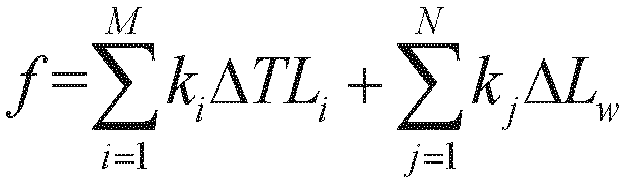
- step S102 the constraint on a total cost for in-vehicle noise reduction is expressed as where L pi represents the target noise value, ⁇ TL i represents an increment of the sound transmission loss of each of the different regions of the to-be-designed vehicle, ⁇ L w represents a decrement of the sound power of each of the sound source devices, i ranges from 1 to M, where M represents a total number of the different regions of the to-be-designed vehicle and is a positive integer greater than 1, and j ranges from 1 to N, where N represents a total number of the sound source devices of the to-be-designed vehicle and is a positive integer greater than 1.
- the sound transmission losses TL i of the different regions include a sound transmission loss of any one or more of following regions of the vehicle: a floor, a side wall, a roof, an end wall, a passenger compartment side door, a driver's cab door, a window, a windshield, and a front end of the driver's cab.
- the sound powers L wj of the sound source devices include a sound power of any one or more of a wheel and rail, an air conditioner, a traction converter, an auxiliary converter, a traction motor, an air compressor, and a gear box.
- the initial sound transmission losses are determined based on initial design parameters of the different regions of the vehicle.
- the initial sound powers are determined based on initial design parameters of the sound sources devices.
- the preset difference may be equal to 3, 5 or the like, which is set based on an actual situation and is not specifically limited herein.
- step S103 acquire a design parameter of each of the different regions of the to-be-designed vehicle and a design parameter of each of the sound source devices which are used to obtain the predicted noise value L psi .
- the predicted noise value L psi is obtained when the minimum total cost for in-vehicle noise reduction is satisfied, and the design parameter of each of the different regions of the to-be-designed vehicle and the design parameter of each of the sound source devices used to obtain the predicted noise value L psi are acquired.
- the design parameters of the different regions of the to-be-designed vehicle used to obtain the predicted noise value L psi include: a thickness and material of the floor of the vehicle, a thickness and material of the side wall of the vehicle, a thickness and material of the roof of the vehicle, a thickness and material of the end wall of the vehicle, a thickness and material of the passenger compartment side door of the vehicle, a thickness and material of the driver's cab door of the vehicle, a thickness and material of the window of the vehicle, a thickness and material of the windshield of the vehicle, and a thickness and material of the front end of the driver's cab of the vehicle.
- the design parameters of the sound source devices of the to-be-designed vehicle used to obtain the predicted noise value L psi include: the sound power of the wheel and rail of the vehicle, the sound power of the air conditioner of the vehicle, the sound power of the traction converter of the vehicle, the sound power of the auxiliary converter of the vehicle, the sound power of the traction motor of the vehicle, the sound power of the air compressor of the vehicle, and the sound power of the gear box of the vehicle.
- step S104 design a vehicle based on the design parameter of each of the different regions of the to-be-designed vehicle and the design parameter of each of the sound source devices.
- the vehicle is designed based on the design parameter of each of the different regions of the to-be-designed vehicle and the design parameter of each of the sound source devices, so as to optimize the in-vehicle noise with the minimum total cost for in-vehicle noise reduction.
- the vehicle is designed based on the following design parameters of the to-be-designed vehicle: the thickness and material of regions of the vehicle such as the floor, the side wall, the roof, the end wall, the passenger compartment side door, the driver's cab door, the window, the windshield and the front end of the driver's cab; and the sound power of auxiliary devices of the vehicle such as the wheel and rail, the air conditioner, the traction converter, the auxiliary converter, the traction motor, the air compressor, and the gear box.
- the thickness and material of regions of the vehicle such as the floor, the side wall, the roof, the end wall, the passenger compartment side door, the driver's cab door, the window, the windshield and the front end of the driver's cab
- the sound power of auxiliary devices of the vehicle such as the wheel and rail, the air conditioner, the traction converter, the auxiliary converter, the traction motor, the air compressor, and the gear box.
- noise prediction is performed based on the in-vehicle noise simulation-prediction-analysis model iteratively to obtain a predicted noise value L psi that has no deviation and takes a minimum total cost for in-vehicle noise reduction, so that the method for optimizing and designing low in-vehicle noise has a short period, low cost, and is not prone to deviation.
- the method does not require any subjective experience from a designer for vehicle design, and thereby has no subjectivity.
- step S102 involves a process of performing the noise prediction based on the in-vehicle noise simulation-prediction-analysis model iteratively with starting with the input of the initial sound transmission losses and the initial sound powers and being under the constraint on a total cost for in-vehicle noise reduction.
- Figure 2 shows a schematic flow chart of the process of performing noise prediction based on the in-vehicle noise simulation-prediction-analysis model iteratively. As shown in Figure 2 , the process includes steps S201 to S208 as follows.
- step S201 acquire initial design parameters of the vehicle.
- the initial design parameters of the vehicle include a design parameter of each of the different regions of the vehicle and a design parameter of each of the sound source devices.
- the design parameters of the different regions of the vehicle include a thickness and material of the following regions of the vehicle: a floor, a side wall, a roof, an end wall, a passenger compartment side door, a driver's cab door, a window, a windshield, a front end of the driver's cab.
- the design parameters of the sound source devices include a sound power of the following sound source devices of the vehicle: a wheel and rail, an air conditioner, a traction converter, an auxiliary converter, a traction motor, an air compressor, a gear box.
- step S202 acquire, based on the design parameter of each of the different regions of the vehicle, the initial sound transmission loss of the region.
- step S202 the initial sound transmission loss depends on an initial design parameter of the different regions of the vehicle.
- An example is provided to facilitate understanding the process of acquiring the initial sound transmission loss of each of the regions based on the design parameter of the region of the vehicle in step S202. For example, it is determined, based on the thickness and material of a side wall of the vehicle, that the initial sound transmission loss of the side wall of the vehicle is 20db; and it is determined, based on the thickness and material of a roof of the vehicle, that the initial sound transmission loss of the roof of the vehicle is 35db.
- step S203 acquire, based on the design parameter of each of the sound source devices, the initial sound power of the sound source device.
- the initial sound power depends on an initial design parameter of the sound source device.
- An example is provided to facilitate understanding the process of acquiring the initial sound power of each of the sound source devices based on the design parameter of the sound source device in step S203. For example, it is determined that the initial sound power of the sound source device being a wheel and rail is 110db based on the sound source device being a wheel and rail, and it is determined that the initial sound transmission loss of the sound source device being an air conditioner is 76db based on the sound source device being an air conditioner.
- step S204 perform the noise prediction by inputting the initial sound transmission loss of each of the regions and the initial sound power of each of the sound source devices to the in-vehicle noise simulation-prediction-analysis model, to obtain an initial predicted noise value.
- the predicted noise value that satisfies the minimum total cost for in-vehicle noise reduction is required to be outputted, it is required to input the initial sound transmission loss of each of the regions and the initial sound power of each of the sound source devices to the in-vehicle noise simulation-prediction-analysis model for noise prediction to obtain an initial predicted noise value, and then the noise prediction is performed based on the in-vehicle noise simulation-prediction-analysis model iteratively with starting with the initial sound transmission losses and the initial sound powers, until the predicted noise value L psi that satisfies the minimum total cost for in-vehicle noise reduction is outputted.
- step S205 perform calculation under the constraint on a total cost for in-vehicle noise reduction and based on a multivariate non-linear programming theory, to obtain the minimum total cost for in-vehicle noise reduction, the increment ⁇ TL i of the sound transmission loss of each of the different regions under the minimum total cost for in-vehicle noise reduction, and the decrement ⁇ L w of the sound power of each of the sound source devices under the minimum total cost for in-vehicle noise reduction.
- f represents the total cost for in-vehicle noise reduction
- k i represents a cost corresponding to the increment ⁇ TL i of the sound transmission loss
- k j represents a cost corresponding to the decrement ⁇ L w of the sound power.
- the minimum total cost for in-vehicle noise reduction indicates an optimized situation regarding the total cost for in-vehicle noise reduction.
- step S206 determine an acoustic requirement indicated by the increment of the sound transmission loss of each of the different regions under the minimum total cost for in-vehicle noise reduction and an acoustic requirement indicated by the decrement of the sound power of each of the sound source devices under the minimum total cost for in-vehicle noise reduction.
- step S206 a first acoustic requirement of each of the different regions indicated by the increment ⁇ TL i of the sound transmission loss of the region under the minimum total cost is acquired, and a second acoustic requirement of each of the sound source devices indicated by the decrement ⁇ L w of the sound power of the sound source device under the minimum total cost is required.
- the first acoustic requirement characterizes the sound transmission loss of the region under the minimum cost for in-vehicle noise reduction.
- the second acoustic requirement characterizes the sound power of the sound source device under the minimum cost for in-vehicle noise reduction.
- step S207 determine, based on the acoustic requirements, a design parameter and a new sound transmission loss corresponding to a noise reduction scheme for each of the different regions, and a design parameter and a new sound power of each of the sound source devices.
- step S207 a parameter of material for constructing each of the different regions is acquired based on the noise reduction scheme for the region corresponding to the first acoustic requirement, and the new sound transmission loss corresponding to the region is acquired based on the parameter of material.
- An adjusting parameter of each of the sound source devices is acquired based on the noise reduction scheme for the sound source device corresponding to the second acoustic requirement, and the new sound power corresponding to the sound source device is acquired based on the adjusting parameter.
- An example is provided to facilitate understanding the process of acquiring a parameter of material for constructing each of the different regions based on the noise reduction scheme for the region corresponding to the first acoustic requirement and acquiring the new sound transmission loss corresponding to the region based on the parameter of material in step S207.
- the noise reduction scheme is to apply carbon fiber cotton material with a thickness of 3cm onto the floor based on the sound transmission loss being 42db, and a value of the new sound transmission loss of the floor is 35db based on the carbon fiber cotton material with a thickness of 3cm.
- An example is provided to facilitate understanding the process of acquiring an adjusting parameter of each of the sound source devices based on the noise reduction scheme for the sound source device corresponding to the second acoustic requirement, and acquiring the new sound power corresponding to the sound source device based on the adjusting parameter in step S207.
- step S208 perform the noise prediction by inputting the new sound transmission losses and the new sound powers to the in-vehicle noise simulation-prediction-analysis model, until the predicted noise value L psi satisfying the minimum total cost for in-vehicle noise reduction is outputted and the difference between the predicted noise value L psi and the target noise value L pi is less than the preset difference.
- An example is provided as follows to facilitate understanding of the process of perform the noise prediction by inputting the new sound transmission losses and the new sound powers to the in-vehicle noise simulation-prediction-analysis model, until the predicted noise value L psi satisfying the minimum total cost for in-vehicle noise reduction is outputted.
- the new sound transmission loss and the new sound power are inputted to the in-vehicle noise simulation-prediction-analysis model for noise prediction, if the difference between the predicted noise value L psi and the target noise value L pi is greater than or equal to the preset difference, a second process of acquiring a new sound transmission loss and a new sound power is performed.
- a parameter of material for constructing each of the different regions is acquired based on the noise reduction scheme for the region corresponding to the first acoustic requirement, and a new sound transmission loss corresponding to the region is acquired based on the parameter of material; and an adjusting parameter of each of the sound source devices is acquired based on the noise reduction scheme for the sound source device corresponding to the second acoustic requirement, and a new sound power corresponding to the sound source device is acquired based on the adjusting parameter.
- the new sound transmission loss and new sound power acquired in the second process are inputted to the in-vehicle noise simulation-prediction-analysis model for noise prediction.
- the process is performed repeatedly until the difference between the outputted predicted noise value L psi and the target noise value L pi is less than the preset difference, then this predicted noise value L psi satisfying the minimum total cost for in-vehicle noise reduction is outputted.
- an in-vehicle noise reduction scheme is optimized based on a cost consideration by using the non-linear programming theory, so as to make the noise reduction scheme efficient enough.
- acoustic requirements of different regions of a vehicle are arranged systematically, reasonably and effectively, so that the designed vehicle has a better noise reduction effect.
- a vehicle is designed based on the design parameter of each of the different regions of the to-be-designed vehicle and the design parameter of each of the sound source devices.
- Figure 3 is a schematic diagram showing a design of a vehicle.
- the design parameters of different regions of the to-be-designed vehicle include: a thickness and material of a side wall, a thickness and material of a roof, a thickness and material of a passenger compartment side door, a thickness and material of a driver's cab door, a thickness and material of a window, a thickness and material of a windshield, a thickness and material of a front end of the driver's cab, and a thickness and material of other regions.
- the design parameters of the sound source devices of the to-be-designed vehicle include: a sound power of a wheel and rail of the vehicle, a sound power of an air conditioner of the vehicle, a sound power of a traction converter of the vehicle, a sound power of an auxiliary converter of the vehicle, a sound power of a traction motor of the vehicle, a sound power of an air compressor of the vehicle, a sound power of a gear box of the vehicle, and a sound power of other auxiliary devices.
- a vehicle is designed based on the design parameters of different regions of the to-be-designed vehicle and the design parameters of the sound source devices of the to-be-designed vehicle, so as to make a noise reduction scheme efficient enough.
- the vehicle is designed by using the design parameters of different regions of the to-be-designed vehicle and the design parameters of the sound source devices of the to-be-designed vehicle in a reasonable and effective manner, without requirement for any subjective experience from a designer, thereby having no subjectivity.
- the system for optimizing and designing low in-vehicle noise mainly includes an establishing unit 401, an output unit 402, an acquiring unit 403, and a design unit 404.
- the establishing unit 401 is configured to acquire sound source distribution characteristics corresponding to different regions of a to-be-designed vehicle and sound source devices respectively, and establish an in-vehicle noise simulation-prediction-analysis model based on the sound source distribution characteristics.
- the in-vehicle noise simulation-prediction-analysis model is established based on a statistical energy analysis theory and the sound source distribution characteristics corresponding to the different regions of the to-be-designed vehicle and the sound source devices.
- the different regions of the to-be designed vehicle mentioned in the description of the establishing unit 401 include a floor, a side wall, a roof, an end wall, a passenger compartment side door, a driver's cab door, a window, a windshield, a front end of the driver's cab, and the like.
- the sound source devices mentioned in the description of the establishing unit 401 include: a wheel and rail, an air conditioner, a traction converter, an auxiliary converter, a traction motor, an air compressor, a gear box, and other auxiliary devices.
- the sound source distribution characteristics are related to the different regions of the to-be-designed vehicle and positions of the sound source devices.
- the different regions of the to-be designed vehicle correspond to different sound source distribution characteristics
- the sound source devices at different positions correspond to different sound source distribution characteristics.
- the output unit 402 is configured to perform noise prediction based on the in-vehicle noise simulation-prediction-analysis model iteratively until a predicted noise value L psi satisfying a minimum total cost for in-vehicle noise reduction is outputted and a difference between the predicted noise value L psi and a target noise value L pi is less than a preset difference, where the noise prediction is performed by taking a sound transmission loss TL i of each of the different regions of the to-be-designed vehicle and a sound power L wj of each of the sound source devices as an input to the in-vehicle noise simulation-prediction-analysis model, the noise prediction starts with an input of initial sound transmission losses and initial sound powers and iterates under a constraint on a total cost for in-vehicle noise reduction.
- L pi represents the target noise value
- ⁇ TL i represents an increment of the sound transmission loss of each of the different regions of the to-be-designed vehicle
- ⁇ L w represents a decrement of the sound power of each of the sound source devices
- i ranges from 1 to M
- M represents a total number of the different regions of the to-be-designed vehicle and is a positive integer greater than
- j ranges from 1 to N, where N represents a total number of the sound source devices of the to-be-designed vehicle and is a positive integer greater than 1.
- the sound transmission losses TL i of the different regions include a sound transmission loss of any one or more of following regions of the vehicle: a floor, a side wall, a roof, an end wall, a passenger compartment side door, a driver's cab door, a window, a windshield, and a front end of the driver's cab.
- the sound powers L wj of the sound source devices include a sound power of any one or more of a wheel and rail, an air conditioner, a traction converter, an auxiliary converter, a traction motor, an air compressor, and a gear box.
- the output unit 402 includes a first acquiring module, a second acquiring module, a third acquiring module, a predicting module, a calculating module, a determining module, a fourth acquiring module, a fifth acquiring module and an output module.
- the first acquiring module is configured to acquire initial design parameters of the vehicle.
- the initial design parameters of the to-be-designed vehicle include a design parameter of each of the different regions of the vehicle and a design parameter of each of the sound source devices.
- the second acquiring module is configured to acquire, based on the design parameter of each of the different regions of the vehicle, the initial sound transmission loss of the region.
- the third acquiring module is configured to acquire, based on the design parameter of each of the sound source devices, the initial sound power of the sound source device.
- the predicting module is configured to perform the noise prediction by inputting the initial sound transmission loss of each of the regions and the initial sound power of each of the sound source devices to the in-vehicle noise simulation-prediction-analysis model, to obtain an initial predicted noise value.
- the calculating module is configured to perform calculation under the constraint on a total cost for in-vehicle noise reduction and based on a multivariate non-linear programming theory, to obtain the minimum total cost for in-vehicle noise reduction, the increment ⁇ TL i of the sound transmission loss of each of the different regions under the minimum total cost for in-vehicle noise reduction, and the decrement ⁇ L w of the sound power of each of the sound source devices under the minimum total cost for in-vehicle noise reduction.
- the calculating module includes a calculating sub-module and a determining sub-module.
- the determining sub-module is configured to determine the increment ⁇ TL i of the sound transmission loss of each of the different regions under the minimum total cost for in-vehicle noise reduction, and the decrement ⁇ L w of the sound power of each of the sound source devices under the minimum total cost for in-vehicle noise reduction.
- the first determining module is configured to determine an acoustic requirement indicated by the increment ⁇ TL i of the sound transmission loss of each of the different regions under the minimum total cost for in-vehicle noise reduction and an acoustic requirement indicated by the decrement ⁇ L w of the sound power of each of the sound source devices under the minimum total cost for in-vehicle noise reduction.
- the second determining module is configured to determine, based on the acoustic requirements, a design parameter and a new sound transmission loss corresponding to a noise reduction scheme for each of the different regions, and a design parameter and a new sound power of each of the sound source devices.
- the output module is configured to perform the noise prediction by inputting the new sound transmission losses and the new sound powers to the in-vehicle noise simulation-prediction-analysis model, until the predicted noise value L psi satisfying the minimum total cost for in-vehicle noise reduction is outputted and the difference between the predicted noise value L psi and the target noise value L pi is less than the preset difference.
- the acquiring unit 403 is configured to acquire a design parameter of each of the different regions of the to-be-designed vehicle and a design parameter of each of the sound source devices which are used to obtain the predicted noise value L psi .
- the predicted noise value L psi is obtained when the minimum total cost for in-vehicle noise reduction is satisfied, and the design parameter of each of the different regions of the to-be-designed vehicle and the design parameter of each of the sound source devices used to obtain the predicted noise value L psi are acquired.
- the design parameters of the different regions of the to-be-designed vehicle used to obtain the predicted noise value L psi include: a thickness and material of the floor of the vehicle, a thickness and material of the side wall of the vehicle, a thickness and material of the roof of the vehicle, a thickness and material of the end wall of the vehicle, a thickness and material of the passenger compartment side door of the vehicle, a thickness and material of the driver's cab door of the vehicle, a thickness and material of the window of the vehicle, a thickness and material of the windshield of the vehicle, and a thickness and material of the front end of the driver's cab of the vehicle.
- the design parameters of the sound source devices of the to-be-designed vehicle used to obtain the predicted noise value L psi include: the sound power of the wheel and rail of the vehicle, the sound power of the air conditioner of the vehicle, the sound power of the traction converter of the vehicle, the sound power of the auxiliary converter of the vehicle, the sound power of the traction motor of the vehicle, the sound power of the air compressor of the vehicle, and the sound power of the gear box of the vehicle.
- the design unit 404 is configured to design a vehicle based on the design parameter of each of the different regions of the to-be-designed vehicle and the design parameter of each of the sound source devices.
- the vehicle is designed based on the design parameter of each of the different regions of the to-be-designed vehicle and the design parameter of each of the sound source devices, such that the in-vehicle noise is optimized under the minimum total cost for in-vehicle noise reduction.
- a system for optimizing and designing low in-vehicle noise is provided according to the embodiments of the present disclosure, in which noise prediction is performed iteratively based on an in-vehicle noise simulation-prediction-analysis model to obtain a predicted noise value L psi that has no deviation and takes a minimum total cost for in-vehicle noise reduction.
- the system for optimizing and designing low in-vehicle noise according to the present disclosure has a short period, low cost, and is not prone to deviation.
- the system does not require any subjective experience from a designer when designing a vehicle, and thereby has no subjectivity.
Landscapes
- Engineering & Computer Science (AREA)
- Physics & Mathematics (AREA)
- Geometry (AREA)
- Theoretical Computer Science (AREA)
- General Physics & Mathematics (AREA)
- Computer Hardware Design (AREA)
- General Engineering & Computer Science (AREA)
- Evolutionary Computation (AREA)
- Aviation & Aerospace Engineering (AREA)
- Pure & Applied Mathematics (AREA)
- Mathematical Optimization (AREA)
- Mathematical Analysis (AREA)
- Computational Mathematics (AREA)
- Automation & Control Theory (AREA)
- Measurement Of Mechanical Vibrations Or Ultrasonic Waves (AREA)
Abstract
Description
- This application claims priority to
Chinese Patent Application No. 202011028783.6, titled "METHOD AND SYSTEM FOR OPTIMIZING AND DESIGNING LOW IN-VEHICLE NOISE", filed on September 25, 2020 - The present disclosure relates to the technical field of acoustic simulation, and in particular to a method and a system for optimizing and designing low in-vehicle noise.
- With the rapid development of rail transit, a problem of noise of a rail transit vehicle is noticed. The noise of a rail transit vehicle usually includes off-vehicle noise and in-vehicle noise.
- There are two methods mainly applied for researching noise of a rail transit vehicle, i.e., experimental analysis method and numerical simulation analysis method. In a process of controlling the in-vehicle noise by the experimental analysis method to improve an acoustic environment in a vehicle, many attempts and tests are performed to achieve the purpose of optimizing the in-vehicle noise. However, the experimental analysis method has problems of long period and high cost. In a process of controlling the in-vehicle noise by the numerical simulation analysis method, an experienced acoustic system engineer usually estimates a sound transmission loss required for each part of a body structure and sound source emitted from each device based on a target value of the in-vehicle noise in a vehicle design stage, and guides a low noise design for the vehicle based on the estimated value, thereby achieving the purpose of optimizing the in-vehicle noise. However, the numerical simulation analysis method significantly depends on subjective experience of the acoustic system engineer, and thus has problems of strong subjectivity and being prone to deviation.
- It can be seen that the existing methods for optimizing and designing low in-vehicle noise has problems of long period, high cost, strong subjectivity, and being prone to deviation.
- In view of this, a method and a system for optimizing and designing low in-vehicle noise is provided according embodiments of the present disclosure, in order to solve the problems of long period, high cost, strong subjectivity, and being prone to deviation existing in the conventional solution for optimizing the in-vehicle noise.
- Technical solutions to achieve the objective are provided as follows according to embodiments of the present disclosure.
- According a first aspect of the present disclosure, a method for optimizing and designing low in-vehicle noise is provided. The method includes:
- acquiring sound source distribution characteristics corresponding to different regions of a to-be-designed vehicle and sound source devices respectively, and establishing an in-vehicle noise simulation-prediction-analysis model based on the sound source distribution characteristics;
- performing noise prediction based on the in-vehicle noise simulation-prediction-analysis model iteratively until a predicted noise value Lpsi satisfying a minimum total cost for in-vehicle noise reduction is outputted and a difference between the predicted noise value Lpsi and a target noise value Lpi is less than a preset difference, where the noise prediction is performed by taking a sound transmission loss TLi of each of the different regions of the to-be-designed vehicle and a sound power Lwj of each of the sound source devices as an input to the in-vehicle noise simulation-prediction-analysis model, the noise prediction starts with an input of initial sound transmission losses and initial sound powers and iterates under a constraint on a total cost for in-vehicle noise reduction, and where the constraint on a total cost for in-vehicle noise reduction is expressed as

- acquiring a design parameter of each of the different regions of the to-be-designed vehicle and a design parameter of each of the sound source devices which are used to obtain the predicted noise value Lpsi ; and
- designing a vehicle based on the design parameter of each of the different regions of the to-be-designed vehicle and the design parameter of each of the sound source devices.
- In a preferred embodiment, a process of performing the noise prediction based on the in-vehicle noise simulation-prediction-analysis model iteratively with starting with the input of the initial sound transmission losses and the initial sound powers and being under the constraint on a total cost for in-vehicle noise reduction includes:
- acquiring initial design parameters of the vehicle, where the initial design parameters of the vehicle include a design parameter of each of the different regions of the vehicle and a design parameter of each of the sound source devices;
- acquiring, based on the design parameter of each of the different regions of the vehicle, the initial sound transmission loss of the region;
- acquiring, based on the design parameter of each of the sound source devices, the initial sound power of the sound source device;
- performing the noise prediction by inputting the initial sound transmission loss of each of the regions and the initial sound power of each of the sound source devices to the in-vehicle noise simulation-prediction-analysis model, to obtain an initial predicted noise value;
- performing calculation under the constraint on a total cost for in-vehicle noise reduction and based on a multivariate non-linear programming theory, to obtain the minimum total cost for in-vehicle noise reduction, the increment ΔTLi of the sound transmission loss of each of the different regions under the minimum total cost for in-vehicle noise reduction, and the decrement ΔLw of the sound power of each of the sound source devices under the minimum total cost for in-vehicle noise reduction;
- determining an acoustic requirement indicated by the increment ΔTLi of the sound transmission loss of each of the different regions under the minimum total cost for in-vehicle noise reduction and an acoustic requirement indicated by the decrement ΔLw of the sound power of each of the sound source devices under the minimum total cost for in-vehicle noise reduction;
- determining, based on the acoustic requirements, a design parameter and a new sound transmission loss corresponding to a noise reduction scheme for each of the different regions, and a design parameter and a new sound power of each of the sound source devices; and
- performing the noise prediction by inputting the new sound transmission losses and the new sound powers to the in-vehicle noise simulation-prediction-analysis model, until the predicted noise value Lpsi satisfying the minimum total cost for in-vehicle noise reduction is outputted and the difference between the predicted noise value Lpsi and the target noise value Lpi is less than the preset difference.
- In a preferred embodiment, a process of performing calculation under the constraint on a total cost for in-vehicle noise reduction and based on the multivariate non-linear programming theory, to obtain the minimum total cost for in-vehicle noise reduction, the increment ΔTLi of the sound transmission loss of each of the different regions under the minimum total cost for in-vehicle noise reduction, and the decrement ΔLw of the sound power of each of the sound source devices under the minimum total cost for in-vehicle noise reduction includes:
- calculating the minimum total cost for in-vehicle noise reduction under the constraint on a total cost for in-vehicle noise reduction, based on an equation expressing the total cost for in-vehicle noise reduction as
- determining the increment ΔTLi of the sound transmission loss of each of the different regions under the minimum total cost for in-vehicle noise reduction, and the decrement ΔLw of the sound power of each of the sound source devices under the minimum total cost for in-vehicle noise reduction.
- In a preferred embodiment, the sound transmission losses of the different regions include a sound transmission loss of any one or more of following regions of the vehicle: a floor, a side wall, a roof, an end wall, a passenger compartment side door, a driver's cab door, a window, a windshield, and a front end of the driver's cab.
- In a preferred embodiment, the sound powers of the sound source devices include a sound power of any one or more of a wheel and rail, an air conditioner, a traction converter, an auxiliary converter, a traction motor, an air compressor, and a gear box.
- According to a second aspect of the present disclosure, a system for optimizing and designing low in-vehicle noise is provided. The system includes:
- an establishing unit, configured to acquire sound source distribution characteristics corresponding to different regions of a to-be-designed vehicle and sound source devices respectively, and establish an in-vehicle noise simulation-prediction-analysis model based on the sound source distribution characteristics;
- an output unit, configured to perform noise prediction based on the in-vehicle noise simulation-prediction-analysis model iteratively until a predicted noise value Lpsi satisfying a minimum total cost for in-vehicle noise reduction is outputted and a difference between the predicted noise value Lpsi and a target noise value Lpi is less than a preset difference, where the noise prediction is performed by taking a sound transmission loss TLi of each of the different regions of the to-be-designed vehicle and a sound power Lwj of each of the sound source devices as an input to the in-vehicle noise simulation-prediction-analysis model, the noise prediction starts with an input of initial sound transmission losses and initial sound powers and iterates under a constraint on a total cost for in-vehicle noise reduction, and where the constraint on a total cost for in-vehicle noise reduction is expressed as

- where Lpi represents the target noise value, ΔTLi represents an increment of the sound transmission loss of each of the different regions of the to-be-designed vehicle, ΔLw represents a decrement of the sound power of each of the sound source devices, i ranges from 1 to M, where M represents a total number of the different regions of the to-be-designed vehicle and is a positive integer greater than 1, and j ranges from 1 to N, where N represents a total number of the sound source devices of the to-be-designed vehicle and is a positive integer greater than 1;
- an acquiring unit, configured to acquire a design parameter of each of the different regions of the to-be-designed vehicle and a design parameter of each of the sound source devices which are used to obtain the predicted noise value Lpsi ; and
- a design unit, configured to design a vehicle based on the design parameter of each of the different regions of the to-be-designed vehicle and the design parameter of each of the sound source devices.
- In a preferred embodiment, the output unit that performs the noise prediction based on the in-vehicle noise simulation-prediction-analysis model iteratively with starting with the input of the initial sound transmission losses and the initial sound powers and being under the constraint on a total cost for in-vehicle noise reduction includes:
- a first acquiring module configured to acquire initial design parameters of the vehicle, where the initial design parameters of the vehicle include a design parameter of each of the different regions of the vehicle and a design parameter of each of the sound source devices;
- a second acquiring module configured to acquire, based on the design parameter of each of the different regions of the vehicle, the initial sound transmission loss of the region;
- a third acquiring module configured to acquire, based on the design parameter of each of the sound source devices, the initial sound power of the sound source device;
- a predicting module configured to perform the noise prediction by inputting the initial sound transmission loss of each of the regions and the initial sound power of each of the sound source devices to the in-vehicle noise simulation-prediction-analysis model, to obtain an initial predicted noise value;
- a calculating module configured to perform calculation under the constraint on a total cost for in-vehicle noise reduction and based on a multivariate non-linear programming theory, to obtain the minimum total cost for in-vehicle noise reduction, the increment ΔTLi of the sound transmission loss of each of the different regions under the minimum total cost for in-vehicle noise reduction, and the decrement ΔLw of the sound power of each of the sound source devices under the minimum total cost for in-vehicle noise reduction;
- a first determining module configured to determine an acoustic requirement indicated by the increment ΔTLi of the sound transmission loss of each of the different regions under the minimum total cost for in-vehicle noise reduction and an acoustic requirement indicated by the decrement ΔLw of the sound power of each of the sound source devices under the minimum total cost for in-vehicle noise reduction;
- a second determining module configured to determine, based on the acoustic requirements, a design parameter and a new sound transmission loss corresponding to a noise reduction scheme for each of the different regions, and a design parameter and a new sound power of each of the sound source devices; and
- an output module configured to perform the noise prediction by inputting the new sound transmission losses and the new sound powers to the in-vehicle noise simulation-prediction-analysis model, until the predicted noise value Lpsi satisfying the minimum total cost for in-vehicle noise reduction is outputted and the difference between the predicted noise value Lpsi and the target noise value Lpi is less than the preset difference.
- In a preferred embodiment, the calculating module includes:
- a calculating sub-module configured to calculate the minimum total cost for in-vehicle noise reduction under the constraint on a total cost for in-vehicle noise reduction, based on an equation expressing the total cost for in-vehicle noise reduction as

- a determining sub-module configured to determine the increment ΔTLi of the sound transmission loss of each of the different regions under the minimum total cost for in-vehicle noise reduction, and the decrement ΔLw of the sound power of each of the sound source devices under the minimum total cost for in-vehicle noise reduction.
- According to the above technical solutions, a noise prediction is performed iteratively based on the in-vehicle noise simulation-prediction-analysis model, which guarantees to obtain a predicted noise value Lpsi that has no deviation and satisfies a minimum total cost for in-vehicle noise reduction, so that the method for optimizing and designing low in-vehicle noise has a short period, low cost and is not prone to deviation. In addition, the method does not require any subjective experience from a designer for vehicle design, and thereby has no subjectivity.
- For clearer illustration of the technical solutions according to embodiments of the present disclosure or conventional techniques, hereinafter are briefly described the drawings to be applied in embodiments of the present disclosure or conventional technology. Apparently, the drawings in the following descriptions are only some embodiments of the present disclosure, and those skilled in the art can derive other drawings from these drawings without any creative effort.
-
Figure 1 is a schematic flow chart of a method for optimizing and designing low in-vehicle noise according to an embodiment of the present disclosure; -
Figure 2 is a schematic flow chart of a process of performing noise prediction based on an in-vehicle noise simulation-prediction-analysis model iteratively according to an embodiment of the present disclosure; -
Figure 3 is a schematic diagram showing a vehicle design according to an embodiment of the present disclosure; and -
Figure 4 is a schematic structural diagram of a system for optimizing and designing low in-vehicle noise according to an embodiment of the present disclosure. - The technical solutions in the embodiments of the present disclosure are clearly and completely described in the following with reference to the accompanying drawings in the embodiments of the present disclosure. Apparently, the embodiments described herein are only a part rather than all of the embodiments of the present disclosure. Any other embodiments obtained by those skilled in the art based on the embodiments in the present disclosure without any creative work fall within the protection scope of the present disclosure.
- In this specification, terms "include", "comprise" or any other variants thereof are intended to be non-exclusive. Therefore, a process, method, article or device including a series of elements includes not only these elements but also elements that are not enumerated, or elements that are inherent to the process, method, article or device. Unless expressively limited otherwise, a process, method, article or device limited by "comprising/including a(n) ..." does not exclude existence of another identical element in such process, method, article or device.
- As described in the background section, there are two methods mainly applied for researching noise of a rail transit vehicle, i.e., experimental analysis method and numerical simulation analysis method. However, the experimental analysis method has problems of long period and high cost; and the numerical simulation analysis method significantly depends on subjective experience of the acoustic system engineer, and thus has problems of strong subjectivity and being prone to deviation.
- As can be seen, the existing methods for optimizing and designing in-vehicle noise has problems of long period, high cost, strong subjectivity, and being prone to deviation.
- To solve the problems, a method and a system for optimizing and designing low in-vehicle noise are provided, which perform noise prediction based on an in-vehicle noise simulation-prediction-analysis model iteratively to obtain a predicted noise value Lpsi that has no deviation and satisfies a minimum total cost for in-vehicle noise reduction, so as to achieve an objective that the method for optimizing and designing low in-vehicle noise has a short period, low cost and is not prone to deviation. In addition, the method does not require any subjective experience from a designer for vehicle design, and thereby has no subjectivity. The present disclosure solves the problems of long period, high cost, strong subjectivity and easy deviation in the existing solution for optimizing in-vehicle noise. Specific implementations are described in the following embodiments.
-
Figure 1 is a schematic flow chart of a method for optimizing and designing low in-vehicle noise according to an embodiment of the present disclosure. As shown inFigure 1 , the method includes steps S101 to S104 as follows. - In step S101, acquire sound source distribution characteristics corresponding to different regions of a to-be-designed vehicle and sound source devices respectively, and establish an in-vehicle noise simulation-prediction-analysis model based on the sound source distribution characteristics.
- In a specific implementation of step S101, the in-vehicle noise simulation-prediction-analysis model is established based on a statistical energy analysis theory and the sound source distribution characteristics corresponding to the different regions of the to-be-designed vehicle and the sound source devices.
- The different regions of the to-be designed vehicle include a floor, a side wall, a roof, an end wall, a passenger compartment side door, a driver's cab door, a window, a windshield, a front end of the driver's cab, and the like. The sound source devices include: a wheel and rail, an air conditioner, a traction converter, an auxiliary converter, a traction motor, an air compressor, a gear box, and other auxiliary devices.
- The sound source distribution characteristics are related to the different regions of the to-be-designed vehicle and positions of the sound source devices. The different regions of the to-be designed vehicle correspond to different sound source distribution characteristics, and the sound source devices at different positions correspond to different sound source distribution characteristics. When the different regions of the to-be-designed vehicle and positions of the sound source devices are determined, the sound source distribution characteristics corresponding to the different regions of to-be-designed vehicle and the sound source devices may be determined.
- An example is provided to facilitate understanding a process of acquiring sound source distribution characteristics corresponding to different regions of a to-be-designed vehicle and sound source devices. For example, in a case where a sound source device is an air conditioner mounted on a side wall, a sound source distribution characteristic corresponding to such case may be obtained.
- In step S102, perform noise prediction based on the in-vehicle noise simulation-prediction-analysis model iteratively until a predicted noise value Lpsi satisfying a minimum total cost for in-vehicle noise reduction is outputted and a difference between the predicted noise value Lpsi and a target noise value Lpi is less than a preset difference. The noise prediction is performed by taking a sound transmission loss TLi of each of the different regions of the to-be-designed vehicle and a sound power Lwj of each of the sound source devices as an input to the in-vehicle noise simulation-prediction-analysis model, the noise prediction starts with an input of initial sound transmission losses and initial sound powers and iterates under a constraint on a total cost for in-vehicle noise reduction.
- In step S102, the constraint on a total cost for in-vehicle noise reduction is expressed as

- It should be noted that the sound transmission losses TLi of the different regions include a sound transmission loss of any one or more of following regions of the vehicle: a floor, a side wall, a roof, an end wall, a passenger compartment side door, a driver's cab door, a window, a windshield, and a front end of the driver's cab.
- The sound powers Lwj of the sound source devices include a sound power of any one or more of a wheel and rail, an air conditioner, a traction converter, an auxiliary converter, a traction motor, an air compressor, and a gear box.
- The initial sound transmission losses are determined based on initial design parameters of the different regions of the vehicle. The initial sound powers are determined based on initial design parameters of the sound sources devices. The preset difference may be equal to 3, 5 or the like, which is set based on an actual situation and is not specifically limited herein.
- In step S103, acquire a design parameter of each of the different regions of the to-be-designed vehicle and a design parameter of each of the sound source devices which are used to obtain the predicted noise value Lpsi .
- In a specific implementation of step S103, the predicted noise value Lpsi is obtained when the minimum total cost for in-vehicle noise reduction is satisfied, and the design parameter of each of the different regions of the to-be-designed vehicle and the design parameter of each of the sound source devices used to obtain the predicted noise value Lpsi are acquired.
- In an embodiment, the design parameters of the different regions of the to-be-designed vehicle used to obtain the predicted noise value Lpsi include: a thickness and material of the floor of the vehicle, a thickness and material of the side wall of the vehicle, a thickness and material of the roof of the vehicle, a thickness and material of the end wall of the vehicle, a thickness and material of the passenger compartment side door of the vehicle, a thickness and material of the driver's cab door of the vehicle, a thickness and material of the window of the vehicle, a thickness and material of the windshield of the vehicle, and a thickness and material of the front end of the driver's cab of the vehicle.
- The design parameters of the sound source devices of the to-be-designed vehicle used to obtain the predicted noise value Lpsi include: the sound power of the wheel and rail of the vehicle, the sound power of the air conditioner of the vehicle, the sound power of the traction converter of the vehicle, the sound power of the auxiliary converter of the vehicle, the sound power of the traction motor of the vehicle, the sound power of the air compressor of the vehicle, and the sound power of the gear box of the vehicle.
- In step S104, design a vehicle based on the design parameter of each of the different regions of the to-be-designed vehicle and the design parameter of each of the sound source devices.
- The vehicle is designed based on the design parameter of each of the different regions of the to-be-designed vehicle and the design parameter of each of the sound source devices, so as to optimize the in-vehicle noise with the minimum total cost for in-vehicle noise reduction.
- Specifically, the vehicle is designed based on the following design parameters of the to-be-designed vehicle: the thickness and material of regions of the vehicle such as the floor, the side wall, the roof, the end wall, the passenger compartment side door, the driver's cab door, the window, the windshield and the front end of the driver's cab; and the sound power of auxiliary devices of the vehicle such as the wheel and rail, the air conditioner, the traction converter, the auxiliary converter, the traction motor, the air compressor, and the gear box.
- In the method for optimizing and designing low in-vehicle noise according to the embodiments of the present disclosure, noise prediction is performed based on the in-vehicle noise simulation-prediction-analysis model iteratively to obtain a predicted noise value Lpsi that has no deviation and takes a minimum total cost for in-vehicle noise reduction, so that the method for optimizing and designing low in-vehicle noise has a short period, low cost, and is not prone to deviation. In addition, the method does not require any subjective experience from a designer for vehicle design, and thereby has no subjectivity.
- In the method for optimizing and designing low in-vehicle noise disclosed in
Figure 1 according to an embodiment of the present disclosure, step S102 involves a process of performing the noise prediction based on the in-vehicle noise simulation-prediction-analysis model iteratively with starting with the input of the initial sound transmission losses and the initial sound powers and being under the constraint on a total cost for in-vehicle noise reduction.Figure 2 shows a schematic flow chart of the process of performing noise prediction based on the in-vehicle noise simulation-prediction-analysis model iteratively. As shown inFigure 2 , the process includes steps S201 to S208 as follows. - In step S201, acquire initial design parameters of the vehicle.
- The initial design parameters of the vehicle include a design parameter of each of the different regions of the vehicle and a design parameter of each of the sound source devices.
- The design parameters of the different regions of the vehicle include a thickness and material of the following regions of the vehicle: a floor, a side wall, a roof, an end wall, a passenger compartment side door, a driver's cab door, a window, a windshield, a front end of the driver's cab.
- The design parameters of the sound source devices include a sound power of the following sound source devices of the vehicle: a wheel and rail, an air conditioner, a traction converter, an auxiliary converter, a traction motor, an air compressor, a gear box.
- In step S202, acquire, based on the design parameter of each of the different regions of the vehicle, the initial sound transmission loss of the region.
- In step S202, the initial sound transmission loss depends on an initial design parameter of the different regions of the vehicle.
- An example is provided to facilitate understanding the process of acquiring the initial sound transmission loss of each of the regions based on the design parameter of the region of the vehicle in step S202. For example, it is determined, based on the thickness and material of a side wall of the vehicle, that the initial sound transmission loss of the side wall of the vehicle is 20db; and it is determined, based on the thickness and material of a roof of the vehicle, that the initial sound transmission loss of the roof of the vehicle is 35db.
- In step S203, acquire, based on the design parameter of each of the sound source devices, the initial sound power of the sound source device.
- The initial sound power depends on an initial design parameter of the sound source device.
- An example is provided to facilitate understanding the process of acquiring the initial sound power of each of the sound source devices based on the design parameter of the sound source device in step S203. For example, it is determined that the initial sound power of the sound source device being a wheel and rail is 110db based on the sound source device being a wheel and rail, and it is determined that the initial sound transmission loss of the sound source device being an air conditioner is 76db based on the sound source device being an air conditioner.
- In step S204, perform the noise prediction by inputting the initial sound transmission loss of each of the regions and the initial sound power of each of the sound source devices to the in-vehicle noise simulation-prediction-analysis model, to obtain an initial predicted noise value.
- Since the predicted noise value that satisfies the minimum total cost for in-vehicle noise reduction is required to be outputted, it is required to input the initial sound transmission loss of each of the regions and the initial sound power of each of the sound source devices to the in-vehicle noise simulation-prediction-analysis model for noise prediction to obtain an initial predicted noise value, and then the noise prediction is performed based on the in-vehicle noise simulation-prediction-analysis model iteratively with starting with the initial sound transmission losses and the initial sound powers, until the predicted noise value Lpsi that satisfies the minimum total cost for in-vehicle noise reduction is outputted.
- In step S205, perform calculation under the constraint on a total cost for in-vehicle noise reduction and based on a multivariate non-linear programming theory, to obtain the minimum total cost for in-vehicle noise reduction, the increment ΔTLi of the sound transmission loss of each of the different regions under the minimum total cost for in-vehicle noise reduction, and the decrement ΔLw of the sound power of each of the sound source devices under the minimum total cost for in-vehicle noise reduction.
- Specifically, a process of obtaining the minimum total cost for in-vehicle noise reduction, the increment ΔTLi of the sound transmission loss of each of the different regions under the minimum total cost for in-vehicle noise reduction, and the decrement ΔLw of the sound power of each of the sound source devices under the minimum total cost for in-vehicle noise reduction is described as follows.
- First, the minimum total cost for in-vehicle noise reduction is calculated under the constraint on a total cost for in-vehicle noise reduction, based on an equation expressing the total cost for in-vehicle noise reduction as

- In the description, f represents the total cost for in-vehicle noise reduction, ki represents a cost corresponding to the increment ΔTLi of the sound transmission loss, and kj represents a cost corresponding to the decrement ΔLw of the sound power. The minimum total cost for in-vehicle noise reduction indicates an optimized situation regarding the total cost for in-vehicle noise reduction.
- An example is provided to facilitate understanding the process of adjusting the increment ΔTLi of the sound transmission loss. For example, a value of the sound transmission loss of a floor is 10db and is required to be increased to 12db, then the increment ΔTLi of the sound transmission loss of the floor is calculated as 12db-10db=2db. An example is provided to facilitate understanding the process of adjusting the decrement ΔLw of the sound power of the sound source device. For example, a value of the sound power of an air conditioner is 110db and is required to be decreased to 100db, then the decrement ΔLw of the sound power of the air conditioner is calculated as 110db-100db=10db.
- In step S206, determine an acoustic requirement indicated by the increment of the sound transmission loss of each of the different regions under the minimum total cost for in-vehicle noise reduction and an acoustic requirement indicated by the decrement of the sound power of each of the sound source devices under the minimum total cost for in-vehicle noise reduction.
- In step S206, a first acoustic requirement of each of the different regions indicated by the increment ΔTLi of the sound transmission loss of the region under the minimum total cost is acquired, and a second acoustic requirement of each of the sound source devices indicated by the decrement ΔLw of the sound power of the sound source device under the minimum total cost is required. The first acoustic requirement characterizes the sound transmission loss of the region under the minimum cost for in-vehicle noise reduction. The second acoustic requirement characterizes the sound power of the sound source device under the minimum cost for in-vehicle noise reduction.
- In step S207, determine, based on the acoustic requirements, a design parameter and a new sound transmission loss corresponding to a noise reduction scheme for each of the different regions, and a design parameter and a new sound power of each of the sound source devices.
- In step S207, a parameter of material for constructing each of the different regions is acquired based on the noise reduction scheme for the region corresponding to the first acoustic requirement, and the new sound transmission loss corresponding to the region is acquired based on the parameter of material. An adjusting parameter of each of the sound source devices is acquired based on the noise reduction scheme for the sound source device corresponding to the second acoustic requirement, and the new sound power corresponding to the sound source device is acquired based on the adjusting parameter.
- An example is provided to facilitate understanding the process of acquiring a parameter of material for constructing each of the different regions based on the noise reduction scheme for the region corresponding to the first acoustic requirement and acquiring the new sound transmission loss corresponding to the region based on the parameter of material in step S207. For example, if a value of the sound transmission loss of the floor is 42db, the noise reduction scheme is to apply carbon fiber cotton material with a thickness of 3cm onto the floor based on the sound transmission loss being 42db, and a value of the new sound transmission loss of the floor is 35db based on the carbon fiber cotton material with a thickness of 3cm.
- An example is provided to facilitate understanding the process of acquiring an adjusting parameter of each of the sound source devices based on the noise reduction scheme for the sound source device corresponding to the second acoustic requirement, and acquiring the new sound power corresponding to the sound source device based on the adjusting parameter in step S207. For example, if a value of the sound power of the air conditioner is 76db, the noise reduction scheme is to decreases the sound power of the air conditioner to 50db, that is, an adjusting parameter of the air conditioner is calculated as 76db-50db=26db, and a value of the new sound power of the air conditioner is obtained as 50db based on the adjusting parameter 26db.
- In step S208, perform the noise prediction by inputting the new sound transmission losses and the new sound powers to the in-vehicle noise simulation-prediction-analysis model, until the predicted noise value Lpsi satisfying the minimum total cost for in-vehicle noise reduction is outputted and the difference between the predicted noise value Lpsi and the target noise value Lpi is less than the preset difference.
- An example is provided as follows to facilitate understanding of the process of perform the noise prediction by inputting the new sound transmission losses and the new sound powers to the in-vehicle noise simulation-prediction-analysis model, until the predicted noise value Lpsi satisfying the minimum total cost for in-vehicle noise reduction is outputted. For example, the new sound transmission loss and the new sound power are inputted to the in-vehicle noise simulation-prediction-analysis model for noise prediction, if the difference between the predicted noise value Lpsi and the target noise value Lpi is greater than or equal to the preset difference, a second process of acquiring a new sound transmission loss and a new sound power is performed. In the second process, a parameter of material for constructing each of the different regions is acquired based on the noise reduction scheme for the region corresponding to the first acoustic requirement, and a new sound transmission loss corresponding to the region is acquired based on the parameter of material; and an adjusting parameter of each of the sound source devices is acquired based on the noise reduction scheme for the sound source device corresponding to the second acoustic requirement, and a new sound power corresponding to the sound source device is acquired based on the adjusting parameter. The new sound transmission loss and new sound power acquired in the second process are inputted to the in-vehicle noise simulation-prediction-analysis model for noise prediction. The process is performed repeatedly until the difference between the outputted predicted noise value Lpsi and the target noise value Lpi is less than the preset difference, then this predicted noise value Lpsi satisfying the minimum total cost for in-vehicle noise reduction is outputted.
- According to the embodiment of the present disclosure, an in-vehicle noise reduction scheme is optimized based on a cost consideration by using the non-linear programming theory, so as to make the noise reduction scheme efficient enough. In this way, acoustic requirements of different regions of a vehicle are arranged systematically, reasonably and effectively, so that the designed vehicle has a better noise reduction effect.
- In the aforementioned step S104, a vehicle is designed based on the design parameter of each of the different regions of the to-be-designed vehicle and the design parameter of each of the sound source devices.
Figure 3 is a schematic diagram showing a design of a vehicle. - In
Figure 3 , the design parameters of different regions of the to-be-designed vehicle include: a thickness and material of a side wall, a thickness and material of a roof, a thickness and material of a passenger compartment side door, a thickness and material of a driver's cab door, a thickness and material of a window, a thickness and material of a windshield, a thickness and material of a front end of the driver's cab, and a thickness and material of other regions. - The design parameters of the sound source devices of the to-be-designed vehicle include: a sound power of a wheel and rail of the vehicle, a sound power of an air conditioner of the vehicle, a sound power of a traction converter of the vehicle, a sound power of an auxiliary converter of the vehicle, a sound power of a traction motor of the vehicle, a sound power of an air compressor of the vehicle, a sound power of a gear box of the vehicle, and a sound power of other auxiliary devices.
- In the embodiment of the present disclosure, a vehicle is designed based on the design parameters of different regions of the to-be-designed vehicle and the design parameters of the sound source devices of the to-be-designed vehicle, so as to make a noise reduction scheme efficient enough. In this way, the vehicle is designed by using the design parameters of different regions of the to-be-designed vehicle and the design parameters of the sound source devices of the to-be-designed vehicle in a reasonable and effective manner, without requirement for any subjective experience from a designer, thereby having no subjectivity.
- Based on the method for optimizing and designing low in-vehicle noise disclosed in the embodiment referring to
Figure 1 , a system for optimizing and designing low in-vehicle noise is disclosed according to an embodiment of the present disclosure. As shown inFigure 4 , the system for optimizing and designing low in-vehicle noise mainly includes an establishingunit 401, anoutput unit 402, an acquiringunit 403, and adesign unit 404. - The establishing
unit 401 is configured to acquire sound source distribution characteristics corresponding to different regions of a to-be-designed vehicle and sound source devices respectively, and establish an in-vehicle noise simulation-prediction-analysis model based on the sound source distribution characteristics. - The in-vehicle noise simulation-prediction-analysis model is established based on a statistical energy analysis theory and the sound source distribution characteristics corresponding to the different regions of the to-be-designed vehicle and the sound source devices.
- The different regions of the to-be designed vehicle mentioned in the description of the establishing
unit 401 include a floor, a side wall, a roof, an end wall, a passenger compartment side door, a driver's cab door, a window, a windshield, a front end of the driver's cab, and the like. - The sound source devices mentioned in the description of the establishing
unit 401 include: a wheel and rail, an air conditioner, a traction converter, an auxiliary converter, a traction motor, an air compressor, a gear box, and other auxiliary devices. - The sound source distribution characteristics are related to the different regions of the to-be-designed vehicle and positions of the sound source devices. The different regions of the to-be designed vehicle correspond to different sound source distribution characteristics, and the sound source devices at different positions correspond to different sound source distribution characteristics.
- The
output unit 402 is configured to perform noise prediction based on the in-vehicle noise simulation-prediction-analysis model iteratively until a predicted noise value Lpsi satisfying a minimum total cost for in-vehicle noise reduction is outputted and a difference between the predicted noise value Lpsi and a target noise value Lpi is less than a preset difference, where the noise prediction is performed by taking a sound transmission loss TLi of each of the different regions of the to-be-designed vehicle and a sound power Lwj of each of the sound source devices as an input to the in-vehicle noise simulation-prediction-analysis model, the noise prediction starts with an input of initial sound transmission losses and initial sound powers and iterates under a constraint on a total cost for in-vehicle noise reduction. - The constraint on a total cost for in-vehicle noise reduction is expressed as

- The sound transmission losses TLi of the different regions include a sound transmission loss of any one or more of following regions of the vehicle: a floor, a side wall, a roof, an end wall, a passenger compartment side door, a driver's cab door, a window, a windshield, and a front end of the driver's cab.
- The sound powers Lwj of the sound source devices include a sound power of any one or more of a wheel and rail, an air conditioner, a traction converter, an auxiliary converter, a traction motor, an air compressor, and a gear box.
- In a further embodiment, the
output unit 402 includes a first acquiring module, a second acquiring module, a third acquiring module, a predicting module, a calculating module, a determining module, a fourth acquiring module, a fifth acquiring module and an output module. - The first acquiring module is configured to acquire initial design parameters of the vehicle. The initial design parameters of the to-be-designed vehicle include a design parameter of each of the different regions of the vehicle and a design parameter of each of the sound source devices.
- The second acquiring module is configured to acquire, based on the design parameter of each of the different regions of the vehicle, the initial sound transmission loss of the region.
- The third acquiring module is configured to acquire, based on the design parameter of each of the sound source devices, the initial sound power of the sound source device.
- The predicting module is configured to perform the noise prediction by inputting the initial sound transmission loss of each of the regions and the initial sound power of each of the sound source devices to the in-vehicle noise simulation-prediction-analysis model, to obtain an initial predicted noise value.
- The calculating module is configured to perform calculation under the constraint on a total cost for in-vehicle noise reduction and based on a multivariate non-linear programming theory, to obtain the minimum total cost for in-vehicle noise reduction, the increment ΔTLi of the sound transmission loss of each of the different regions under the minimum total cost for in-vehicle noise reduction, and the decrement ΔLw of the sound power of each of the sound source devices under the minimum total cost for in-vehicle noise reduction.
- In a further embodiment, the calculating module includes a calculating sub-module and a determining sub-module.
- The calculating sub-module is configured to calculate the minimum total cost for in-vehicle noise reduction under the constraint on a total cost for in-vehicle noise reduction, based on an equation expressing the total cost for in-vehicle noise reduction as

where ki represents a cost corresponding to the increment ΔTLi of the sound transmission loss, and kj represents a cost corresponding to the decrement ΔLw of the sound power. - The determining sub-module is configured to determine the increment ΔTLi of the sound transmission loss of each of the different regions under the minimum total cost for in-vehicle noise reduction, and the decrement ΔLw of the sound power of each of the sound source devices under the minimum total cost for in-vehicle noise reduction.
- The first determining module is configured to determine an acoustic requirement indicated by the increment ΔTLi of the sound transmission loss of each of the different regions under the minimum total cost for in-vehicle noise reduction and an acoustic requirement indicated by the decrement ΔLw of the sound power of each of the sound source devices under the minimum total cost for in-vehicle noise reduction.
- The second determining module is configured to determine, based on the acoustic requirements, a design parameter and a new sound transmission loss corresponding to a noise reduction scheme for each of the different regions, and a design parameter and a new sound power of each of the sound source devices.
- The output module is configured to perform the noise prediction by inputting the new sound transmission losses and the new sound powers to the in-vehicle noise simulation-prediction-analysis model, until the predicted noise value Lpsi satisfying the minimum total cost for in-vehicle noise reduction is outputted and the difference between the predicted noise value Lpsi and the target noise value Lpi is less than the preset difference.
- The acquiring
unit 403 is configured to acquire a design parameter of each of the different regions of the to-be-designed vehicle and a design parameter of each of the sound source devices which are used to obtain the predicted noise value Lpsi . - The predicted noise value Lpsi is obtained when the minimum total cost for in-vehicle noise reduction is satisfied, and the design parameter of each of the different regions of the to-be-designed vehicle and the design parameter of each of the sound source devices used to obtain the predicted noise value Lpsi are acquired.
- The design parameters of the different regions of the to-be-designed vehicle used to obtain the predicted noise value Lpsi include: a thickness and material of the floor of the vehicle, a thickness and material of the side wall of the vehicle, a thickness and material of the roof of the vehicle, a thickness and material of the end wall of the vehicle, a thickness and material of the passenger compartment side door of the vehicle, a thickness and material of the driver's cab door of the vehicle, a thickness and material of the window of the vehicle, a thickness and material of the windshield of the vehicle, and a thickness and material of the front end of the driver's cab of the vehicle.
- The design parameters of the sound source devices of the to-be-designed vehicle used to obtain the predicted noise value Lpsi include: the sound power of the wheel and rail of the vehicle, the sound power of the air conditioner of the vehicle, the sound power of the traction converter of the vehicle, the sound power of the auxiliary converter of the vehicle, the sound power of the traction motor of the vehicle, the sound power of the air compressor of the vehicle, and the sound power of the gear box of the vehicle.
- The
design unit 404 is configured to design a vehicle based on the design parameter of each of the different regions of the to-be-designed vehicle and the design parameter of each of the sound source devices. - The vehicle is designed based on the design parameter of each of the different regions of the to-be-designed vehicle and the design parameter of each of the sound source devices, such that the in-vehicle noise is optimized under the minimum total cost for in-vehicle noise reduction.
- A system for optimizing and designing low in-vehicle noise is provided according to the embodiments of the present disclosure, in which noise prediction is performed iteratively based on an in-vehicle noise simulation-prediction-analysis model to obtain a predicted noise value Lpsi that has no deviation and takes a minimum total cost for in-vehicle noise reduction. The system for optimizing and designing low in-vehicle noise according to the present disclosure has a short period, low cost, and is not prone to deviation. In addition, the system does not require any subjective experience from a designer when designing a vehicle, and thereby has no subjectivity.
- The above method embodiments are described as combinations of a series of actions for the sake of brevity, but those skilled in the art should understand that the present disclosure is not limited to the described sequence of the actions, because some of the steps can be performed in another sequence or concurrently according to the present disclosure. In addition, those skilled in the art should also understand that embodiments described in the specification are preferred embodiments. Actions and modules involved in these embodiments are not necessarily required for the present disclosure.
- It is noted that the embodiments in this specification are described in a progressive manner. Each embodiment focuses on any difference from others, and the same or similar parts among the embodiments can be referred to each other. The system embodiment is basically similar to the method embodiment, and therefore is described briefly, and for related parts, reference may be made to descriptions of the method embodiment.
- The steps in the method according to the embodiments of the present disclosure may be adjusted, combined and deleted as needed.
- It should be further noted that, the relationship terms such as "first", "second" and the like are used herein merely to distinguish one entity or operation from another, rather than to necessitate or imply existence of the actual relationship or order of the entities or operations.
- Those skilled in the art can implement or practice the present disclosure based on the above description of the disclosed embodiments. Various modifications to these embodiments are obvious to those skilled in the art. The general principles defined in the present disclosure may be implemented in other embodiments without departing from the spirit and scope of the present disclosure. Therefore, the present disclosure should not be limited to the embodiments disclosed herein, but conforms to the widest scope consistent with the principle and novel features disclosed in the specification.
- The above description is only preferable embodiments of the present disclosure. It should be noted that those skilled in the art can make improvements and modifications without departing from the principle of the present disclosure. These improvements and modifications shall also fall within the protection scope of the present disclosure.
Claims (8)
- A method for optimizing and designing low in-vehicle noise, comprising:acquiring sound source distribution characteristics corresponding to different regions of a to-be-designed vehicle and sound source devices respectively, and establishing an in-vehicle noise simulation-prediction-analysis model based on the sound source distribution characteristics;performing noise prediction based on the in-vehicle noise simulation-prediction-analysis model iteratively until a predicted noise value Lpsi satisfying a minimum total cost for in-vehicle noise reduction is outputted and a difference between the predicted noise value Lpsi and a target noise value Lpi is less than a preset difference, wherein the noise prediction is performed by taking a sound transmission loss TLi of each of the different regions of the to-be-designed vehicle and a sound power Lwj of each of the sound source devices as an input to the in-vehicle noise simulation-prediction-analysis model, the noise prediction starts with an input of initial sound transmission losses and initial sound powers and iterates under a constraint on a total cost for in-vehicle noise reduction, and wherein the constraint on a total cost for in-vehicle noise reduction is expressed as
 acquiring a design parameter of each of the different regions of the to-be-designed vehicle and a design parameter of each of the sound source devices which are used to obtain the predicted noise value Lpsi ; anddesigning a vehicle based on the design parameter of each of the different regions of the to-be-designed vehicle and the design parameter of each of the sound source devices.
 - The method according to claim 1, wherein a process of performing the noise prediction based on the in-vehicle noise simulation-prediction-analysis model iteratively with starting with the input of the initial sound transmission losses and the initial sound powers and being under the constraint on a total cost for in-vehicle noise reduction comprises:acquiring initial design parameters of the vehicle, wherein the initial design parameters of the vehicle comprise a design parameter of each of the different regions of the vehicle and a design parameter of each of the sound source devices;acquiring, based on the design parameter of each of the different regions of the vehicle, the initial sound transmission loss of the region;acquiring, based on the design parameter of each of the sound source devices, the initial sound power of the sound source device;performing the noise prediction by inputting the initial sound transmission loss of each of the regions and the initial sound power of each of the sound source devices to the in-vehicle noise simulation-prediction-analysis model, to obtain an initial predicted noise value;performing calculation under the constraint on a total cost for in-vehicle noise reduction and based on a multivariate non-linear programming theory, to obtain the minimum total cost for in-vehicle noise reduction, the increment ΔTLi of the sound transmission loss of each of the different regions under the minimum total cost for in-vehicle noise reduction, and the decrement ΔLw of the sound power of each of the sound source devices under the minimum total cost for in-vehicle noise reduction;determining an acoustic requirement indicated by the increment ΔTLi of the sound transmission loss of each of the different regions under the minimum total cost for in-vehicle noise reduction and an acoustic requirement indicated by the decrement ΔLw of the sound power of each of the sound source devices under the minimum total cost for in-vehicle noise reduction;determining, based on the acoustic requirements, a design parameter and a new sound transmission loss corresponding to a noise reduction scheme for each of the different regions, and a design parameter and a new sound power of each of the sound source devices; andperforming the noise prediction by inputting the new sound transmission losses and the new sound powers to the in-vehicle noise simulation-prediction-analysis model, until the predicted noise value Lpsi satisfying the minimum total cost for in-vehicle noise reduction is outputted and the difference between the predicted noise value Lpsi and the target noise value Lpi is less than the preset difference.
- The method according to claim 2, wherein a process of performing calculation under the constraint on a total cost for in-vehicle noise reduction and based on the multivariate non-linear programming theory, to obtain the minimum total cost for in-vehicle noise reduction, the increment ΔTLi of the sound transmission loss of each of the different regions under the minimum total cost for in-vehicle noise reduction, and the decrement ΔLw of the sound power of each of the sound source devices under the minimum total cost for in-vehicle noise reduction comprises:calculating the minimum total cost for in-vehicle noise reduction under the constraint on a total cost for in-vehicle noise reduction, based on an equation expressing the total cost for in-vehicle noise reduction as
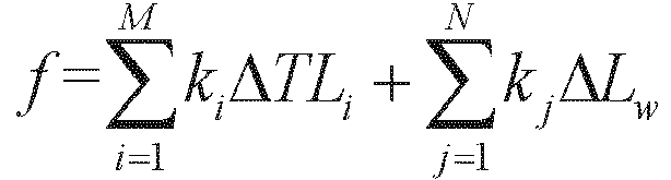 determining the increment ΔTLi of the sound transmission loss of each of the different regions under the minimum total cost for in-vehicle noise reduction, and the decrement ΔLw of the sound power of each of the sound source devices under the minimum total cost for in-vehicle noise reduction.
 - The method according to claim 1, wherein the sound transmission losses of the different regions comprise a sound transmission loss of any one or more of following regions of the vehicle: a floor, a side wall, a roof, an end wall, a passenger compartment side door, a driver's cab door, a window, a windshield, and a front end of the driver's cab.
- The method according to claim 1, wherein the sound powers of the sound source devices comprise a sound power of any one or more of a wheel and rail, an air conditioner, a traction converter, an auxiliary converter, a traction motor, an air compressor, and a gear box.
- A system for optimizing and designing low in-vehicle noise, comprising:an establishing unit, configured to acquire sound source distribution characteristics corresponding to different regions of a to-be-designed vehicle and sound source devices respectively, and establish an in-vehicle noise simulation-prediction-analysis model based on the sound source distribution characteristics;an output unit, configured to perform noise prediction based on the in-vehicle noise simulation-prediction-analysis model iteratively until a predicted noise value Lpsi satisfying a minimum total cost for in-vehicle noise reduction is outputted and a difference between the predicted noise value Lpsi and a target noise value Lpi is less than a preset difference, wherein the noise prediction is performed by taking a sound transmission loss TLi of each of the different regions of the to-be-designed vehicle and a sound power Lwj of each of the sound source devices as an input to the in-vehicle noise simulation-prediction-analysis model, the noise prediction starts with an input of initial sound transmission losses and initial sound powers and iterates under a constraint on a total cost for in-vehicle noise reduction, and wherein the constraint on a total cost for in-vehicle noise reduction is expressed as
 where Lpi represents the target noise value, ΔTLi represents an increment of the sound transmission loss of each of the different regions of the to-be-designed vehicle, ΔLw represents a decrement of the sound power of each of the sound source devices, i ranges from 1 to M, where M represents a total number of the different regions of the to-be-designed vehicle and is a positive integer greater than 1, and j ranges from 1 to N, where N represents a total number of the sound source devices of the to-be-designed vehicle and is a positive integer greater than 1;an acquiring unit, configured to acquire a design parameter of each of the different regions of the to-be-designed vehicle and a design parameter of each of the sound source devices which are used to obtain the predicted noise value Lpsi ; anda design unit, configured to design a vehicle based on the design parameter of each of the different regions of the to-be-designed vehicle and the design parameter of each of the sound source devices.
 - The system according to claim 6, wherein the output unit that performs the noise prediction based on the in-vehicle noise simulation-prediction-analysis model iteratively with starting with the input of the initial sound transmission losses and the initial sound powers and being under the constraint on a total cost for in-vehicle noise reduction comprises:a first acquiring module configured to acquire initial design parameters of the vehicle, wherein the initial design parameters of the vehicle comprise a design parameter of each of the different regions of the vehicle and a design parameter of each of the sound source devices;a second acquiring module configured to acquire, based on the design parameter of each of the different regions of the vehicle, the initial sound transmission loss of the region;a third acquiring module configured to acquire, based on the design parameter of each of the sound source devices, the initial sound power of the sound source device;a predicting module configured to perform the noise prediction by inputting the initial sound transmission loss of each of the regions and the initial sound power of each of the sound source devices to the in-vehicle noise simulation-prediction-analysis model, to obtain an initial predicted noise value;a calculating module configured to perform calculation under the constraint on a total cost for in-vehicle noise reduction and based on a multivariate non-linear programming theory, to obtain the minimum total cost for in-vehicle noise reduction, the increment ΔTLi of the sound transmission loss of each of the different regions under the minimum total cost for in-vehicle noise reduction, and the decrement ΔLw of the sound power of each of the sound source devices under the minimum total cost for in-vehicle noise reduction;a first determining module configured to determine an acoustic requirement indicated by the increment ΔTLi of the sound transmission loss of each of the different regions under the minimum total cost for in-vehicle noise reduction and an acoustic requirement indicated by the decrement ΔLw of the sound power of each of the sound source devices under the minimum total cost for in-vehicle noise reduction;a second determining module configured to determine, based on the acoustic requirements, a design parameter and a new sound transmission loss corresponding to a noise reduction scheme for each of the different regions, and a design parameter and a new sound power of each of the sound source devices; andan output module configured to perform the noise prediction by inputting the new sound transmission losses and the new sound powers to the in-vehicle noise simulation-prediction-analysis model, until the predicted noise value Lpsi satisfying the minimum total cost for in-vehicle noise reduction is outputted and the difference between the predicted noise value Lpsi and the target noise value Lpi is less than the preset difference.
- The system according to claim 7, wherein the calculating module comprises:a calculating sub-module configured to calculate the minimum total cost for in-vehicle noise reduction under the constraint on a total cost for in-vehicle noise reduction, based on an equation expressing the total cost for in-vehicle noise reduction as
 a determining sub-module configured to determine the increment ΔTLi of the sound transmission loss of each of the different regions under the minimum total cost for in-vehicle noise reduction, and the decrement ΔLw of the sound power of each of the sound source devices under the minimum total cost for in-vehicle noise reduction.
Applications Claiming Priority (2)
| Application Number | Priority Date | Filing Date | Title |
|---|---|---|---|
| CN202011028783.6A CN112163274B (en) | 2020-09-25 | 2020-09-25 | Low-noise optimization design method and system in vehicle |
| PCT/CN2020/118669 WO2022061944A1 (en) | 2020-09-25 | 2020-09-29 | Vehicle interior low noise optimization design method, and system |
Publications (2)
| Publication Number | Publication Date |
|---|---|
| EP4002188A1 true EP4002188A1 (en) | 2022-05-25 |
| EP4002188A4 EP4002188A4 (en) | 2022-08-31 |
Family
ID=73862987
Family Applications (1)
| Application Number | Title | Priority Date | Filing Date |
|---|---|---|---|
| EP20934896.0A Pending EP4002188A4 (en) | 2020-09-25 | 2020-09-29 | Vehicle interior low noise optimization design method, and system |
Country Status (3)
| Country | Link |
|---|---|
| EP (1) | EP4002188A4 (en) |
| CN (1) | CN112163274B (en) |
| WO (1) | WO2022061944A1 (en) |
Families Citing this family (10)
| Publication number | Priority date | Publication date | Assignee | Title |
|---|---|---|---|---|
| CN112818539B (en) * | 2021-01-29 | 2022-11-15 | 中车青岛四方机车车辆股份有限公司 | Sound insulation design method and sound insulation design system for window |
| CN113255060B (en) * | 2021-05-27 | 2022-04-15 | 东风汽车集团股份有限公司 | Vehicle sound insulation performance analysis method, system and medium |
| CN113358211B (en) * | 2021-05-28 | 2024-04-30 | 江苏徐工国重实验室科技有限公司 | Noise testing method and device |
| CN113673042B (en) * | 2021-09-06 | 2023-12-12 | 江南造船(集团)有限责任公司 | Ship noise reduction system design method, system, medium and terminal based on acoustic environment simulation |
| CN114000938B (en) * | 2021-11-12 | 2024-04-19 | 无锡威孚力达催化净化器有限责任公司 | Tuning valve opening optimization method |
| CN114280159A (en) * | 2021-12-24 | 2022-04-05 | 智己汽车科技有限公司 | Digital automobile acoustic part simulation method, system and equipment |
| CN114925446A (en) * | 2022-05-05 | 2022-08-19 | 北京汽车股份有限公司 | Design method of sound insulation pad in front wall of automobile and sound insulation pad |
| CN115081339B (en) * | 2022-07-18 | 2025-03-18 | 安徽理工大学 | A method for back-calculating the sound power level of converter transformer based on reliability |
| CN116305599B (en) * | 2022-09-08 | 2026-02-27 | 极光湾(义乌)发动机有限公司 | A method for noise identification and optimization of engine crankshaft system |
| CN115795835B (en) * | 2022-11-18 | 2025-12-19 | 国网江苏省电力有限公司 | Acoustic optimization material selection method and device, electronic equipment and storage medium |
Family Cites Families (10)
| Publication number | Priority date | Publication date | Assignee | Title |
|---|---|---|---|---|
| KR101025163B1 (en) * | 2008-11-14 | 2011-03-31 | 한양대학교 산학협력단 | Vibration and Noise Transmission Path Analysis System and Vibration and Noise Transmission Path Analysis Method |
| CN103971908B (en) * | 2014-05-06 | 2016-03-09 | 国家电网公司 | A kind of transformer noise suppressing method |
| CN105590003A (en) * | 2016-01-05 | 2016-05-18 | 浙江大学 | Interior noise analysis and prediction method of high speed train |
| CN109328380B (en) * | 2016-06-13 | 2023-02-28 | Med-El电气医疗器械有限公司 | Recursive noise power estimation with noise model adaptation |
| CN107745721B (en) * | 2017-10-16 | 2019-08-27 | 中车唐山机车车辆有限公司 | EMU Low Noise Design method |
| CN107862141B (en) * | 2017-11-10 | 2020-08-04 | 西南交通大学 | A low-noise forward design method for rail vehicles |
| CN110875031B (en) * | 2018-08-30 | 2023-10-03 | 株洲中车时代电气股份有限公司 | Track traffic converter noise prediction method |
| CN109323872A (en) * | 2018-10-31 | 2019-02-12 | 中车株洲电力机车有限公司 | A kind of vehicle noise objective decomposition method, the apparatus and system of rail traffic vehicles |
| EP3663943A1 (en) * | 2018-12-07 | 2020-06-10 | Hitachi, Ltd. | Method and system for designing a rail vehicle interior based on simulation of acoustic noise |
| CN110502844B (en) * | 2019-08-27 | 2023-04-07 | 中车株洲电力机车有限公司 | Optimization design method of rail transit vehicle noise digital prototype |
-
2020
- 2020-09-25 CN CN202011028783.6A patent/CN112163274B/en active Active
- 2020-09-29 EP EP20934896.0A patent/EP4002188A4/en active Pending
- 2020-09-29 WO PCT/CN2020/118669 patent/WO2022061944A1/en not_active Ceased
Also Published As
| Publication number | Publication date |
|---|---|
| CN112163274A (en) | 2021-01-01 |
| CN112163274B (en) | 2021-08-06 |
| WO2022061944A1 (en) | 2022-03-31 |
| EP4002188A4 (en) | 2022-08-31 |
Similar Documents
| Publication | Publication Date | Title |
|---|---|---|
| CN112163274B (en) | Low-noise optimization design method and system in vehicle | |
| CN110793621B (en) | Method and system for evaluating order noise of power system of pure electric vehicle | |
| US8880380B2 (en) | Crashworthiness design methodology using a hybrid cellular automata algorithm for the synthesis of topologies for structures subject to nonlinear transient loading | |
| CN113591228B (en) | Noise transmission path analysis and optimization method | |
| CN109323872A (en) | A kind of vehicle noise objective decomposition method, the apparatus and system of rail traffic vehicles | |
| US20070246209A1 (en) | Control method of air-conditioner for hybrid engine vehicle | |
| CN106446423B (en) | Optimum Design Method and Device for Body Structure | |
| ATE269235T1 (en) | VEHICLE DOOR REINFORCEMENT SUPPORT AND METHOD FOR PRODUCING IT | |
| DE102011000450A1 (en) | Support structure for producing e.g. A-pillar of vehicle, has expandable adhesive material between structural element and reinforcement element, which surrounds three sides of portion of reinforcement element facing auxiliary frame | |
| DE102010009611B4 (en) | Motorhome and bulkhead component for a motorhome | |
| CN111527019A (en) | Operation curve creation device, operation assistance device, and operation control device | |
| CN105196833A (en) | Method and device for controlling vehicle-mounted energy-saving automatic air conditioner | |
| KR20140082896A (en) | Method and system for cooling battery | |
| CN111824266B (en) | Side sill assembly for a motor vehicle | |
| CN101010192B (en) | Acoustic damping strips incorporated between the glazing and body of a vehicle | |
| Li et al. | A modelling approach for noise transmission through extruded panels in railway vehicles | |
| CN111562741A (en) | Method for prolonging service life of battery of electric automobile | |
| CN116611337A (en) | In-vehicle wind noise simulation method, system, electronic equipment and storage medium | |
| DE102020205923A1 (en) | Control device and method for controlling an electric drive system and electric drive system | |
| KR101292682B1 (en) | Method for optimizing acoustic comfort in a mobile vehicle passenger compartment | |
| CN104828141A (en) | Transmission shaft installation structure and vehicle having transmission shaft installation structure | |
| US20210039566A1 (en) | Vehicles Including Shaped Reinforcement Brackets for a Headliner | |
| DE102018116439A1 (en) | System and method for active thermal management | |
| CN204340612U (en) | Car door and vehicle | |
| Deng et al. | Study of boundary conditions and parameters effects on TL of the automobile door sealing system |
Legal Events
| Date | Code | Title | Description |
|---|---|---|---|
| STAA | Information on the status of an ep patent application or granted ep patent |
Free format text: STATUS: UNKNOWN |
|
| STAA | Information on the status of an ep patent application or granted ep patent |
Free format text: STATUS: THE INTERNATIONAL PUBLICATION HAS BEEN MADE |
|
| PUAI | Public reference made under article 153(3) epc to a published international application that has entered the european phase |
Free format text: ORIGINAL CODE: 0009012 |
|
| STAA | Information on the status of an ep patent application or granted ep patent |
Free format text: STATUS: REQUEST FOR EXAMINATION WAS MADE |
|
| 17P | Request for examination filed |
Effective date: 20211119 |
|
| AK | Designated contracting states |
Kind code of ref document: A1 Designated state(s): AL AT BE BG CH CY CZ DE DK EE ES FI FR GB GR HR HU IE IS IT LI LT LU LV MC MK MT NL NO PL PT RO RS SE SI SK SM TR |
|
| A4 | Supplementary search report drawn up and despatched |
Effective date: 20220803 |
|
| RIC1 | Information provided on ipc code assigned before grant |
Ipc: G06F 119/10 20200101ALI20220728BHEP Ipc: G06F 30/20 20200101ALI20220728BHEP Ipc: G06F 30/15 20200101AFI20220728BHEP |
|
| DAV | Request for validation of the european patent (deleted) | ||
| DAX | Request for extension of the european patent (deleted) | ||
| STAA | Information on the status of an ep patent application or granted ep patent |
Free format text: STATUS: EXAMINATION IS IN PROGRESS |
|
| 17Q | First examination report despatched |
Effective date: 20240528 |