EP4002109A1 - Programmable display device - Google Patents
Programmable display device Download PDFInfo
- Publication number
- EP4002109A1 EP4002109A1 EP21177495.5A EP21177495A EP4002109A1 EP 4002109 A1 EP4002109 A1 EP 4002109A1 EP 21177495 A EP21177495 A EP 21177495A EP 4002109 A1 EP4002109 A1 EP 4002109A1
- Authority
- EP
- European Patent Office
- Prior art keywords
- section
- setting
- display
- data
- obtaining
- Prior art date
- Legal status (The legal status is an assumption and is not a legal conclusion. Google has not performed a legal analysis and makes no representation as to the accuracy of the status listed.)
- Pending
Links
- 238000000034 method Methods 0.000 claims abstract description 198
- 230000008569 process Effects 0.000 claims abstract description 193
- 230000004044 response Effects 0.000 claims abstract description 17
- 238000007405 data analysis Methods 0.000 claims description 34
- 238000009825 accumulation Methods 0.000 claims description 11
- 230000006870 function Effects 0.000 description 13
- 230000008859 change Effects 0.000 description 4
- 230000007704 transition Effects 0.000 description 4
- 238000004891 communication Methods 0.000 description 3
- 230000009471 action Effects 0.000 description 2
- 230000005540 biological transmission Effects 0.000 description 2
- 238000010586 diagram Methods 0.000 description 2
- 238000003825 pressing Methods 0.000 description 2
- 230000005856 abnormality Effects 0.000 description 1
- 230000004913 activation Effects 0.000 description 1
- 238000004458 analytical method Methods 0.000 description 1
- 238000004364 calculation method Methods 0.000 description 1
- 230000015556 catabolic process Effects 0.000 description 1
- 230000009849 deactivation Effects 0.000 description 1
- 238000006731 degradation reaction Methods 0.000 description 1
- 230000000694 effects Effects 0.000 description 1
- 238000012544 monitoring process Methods 0.000 description 1
- 238000002360 preparation method Methods 0.000 description 1
- 239000004065 semiconductor Substances 0.000 description 1
Images


Classifications
-
- G—PHYSICS
- G06—COMPUTING; CALCULATING OR COUNTING
- G06F—ELECTRIC DIGITAL DATA PROCESSING
- G06F9/00—Arrangements for program control, e.g. control units
- G06F9/06—Arrangements for program control, e.g. control units using stored programs, i.e. using an internal store of processing equipment to receive or retain programs
- G06F9/44—Arrangements for executing specific programs
- G06F9/445—Program loading or initiating
- G06F9/44505—Configuring for program initiating, e.g. using registry, configuration files
-
- G—PHYSICS
- G05—CONTROLLING; REGULATING
- G05B—CONTROL OR REGULATING SYSTEMS IN GENERAL; FUNCTIONAL ELEMENTS OF SUCH SYSTEMS; MONITORING OR TESTING ARRANGEMENTS FOR SUCH SYSTEMS OR ELEMENTS
- G05B19/00—Programme-control systems
- G05B19/02—Programme-control systems electric
- G05B19/04—Programme control other than numerical control, i.e. in sequence controllers or logic controllers
- G05B19/05—Programmable logic controllers, e.g. simulating logic interconnections of signals according to ladder diagrams or function charts
- G05B19/056—Programming the PLC
-
- G—PHYSICS
- G05—CONTROLLING; REGULATING
- G05B—CONTROL OR REGULATING SYSTEMS IN GENERAL; FUNCTIONAL ELEMENTS OF SUCH SYSTEMS; MONITORING OR TESTING ARRANGEMENTS FOR SUCH SYSTEMS OR ELEMENTS
- G05B19/00—Programme-control systems
- G05B19/02—Programme-control systems electric
- G05B19/04—Programme control other than numerical control, i.e. in sequence controllers or logic controllers
- G05B19/05—Programmable logic controllers, e.g. simulating logic interconnections of signals according to ladder diagrams or function charts
- G05B19/058—Safety, monitoring
-
- G—PHYSICS
- G05—CONTROLLING; REGULATING
- G05B—CONTROL OR REGULATING SYSTEMS IN GENERAL; FUNCTIONAL ELEMENTS OF SUCH SYSTEMS; MONITORING OR TESTING ARRANGEMENTS FOR SUCH SYSTEMS OR ELEMENTS
- G05B23/00—Testing or monitoring of control systems or parts thereof
- G05B23/02—Electric testing or monitoring
- G05B23/0205—Electric testing or monitoring by means of a monitoring system capable of detecting and responding to faults
- G05B23/0259—Electric testing or monitoring by means of a monitoring system capable of detecting and responding to faults characterized by the response to fault detection
- G05B23/0267—Fault communication, e.g. human machine interface [HMI]
- G05B23/0272—Presentation of monitored results, e.g. selection of status reports to be displayed; Filtering information to the user
-
- G—PHYSICS
- G06—COMPUTING; CALCULATING OR COUNTING
- G06F—ELECTRIC DIGITAL DATA PROCESSING
- G06F9/00—Arrangements for program control, e.g. control units
- G06F9/06—Arrangements for program control, e.g. control units using stored programs, i.e. using an internal store of processing equipment to receive or retain programs
- G06F9/44—Arrangements for executing specific programs
- G06F9/451—Execution arrangements for user interfaces
-
- G—PHYSICS
- G05—CONTROLLING; REGULATING
- G05B—CONTROL OR REGULATING SYSTEMS IN GENERAL; FUNCTIONAL ELEMENTS OF SUCH SYSTEMS; MONITORING OR TESTING ARRANGEMENTS FOR SUCH SYSTEMS OR ELEMENTS
- G05B2219/00—Program-control systems
- G05B2219/10—Plc systems
- G05B2219/14—Plc safety
- G05B2219/14006—Safety, monitoring in general
-
- G—PHYSICS
- G05—CONTROLLING; REGULATING
- G05B—CONTROL OR REGULATING SYSTEMS IN GENERAL; FUNCTIONAL ELEMENTS OF SUCH SYSTEMS; MONITORING OR TESTING ARRANGEMENTS FOR SUCH SYSTEMS OR ELEMENTS
- G05B2219/00—Program-control systems
- G05B2219/10—Plc systems
- G05B2219/14—Plc safety
- G05B2219/14055—Make log, journal, history file of state changes
-
- G—PHYSICS
- G06—COMPUTING; CALCULATING OR COUNTING
- G06F—ELECTRIC DIGITAL DATA PROCESSING
- G06F3/00—Input arrangements for transferring data to be processed into a form capable of being handled by the computer; Output arrangements for transferring data from processing unit to output unit, e.g. interface arrangements
- G06F3/01—Input arrangements or combined input and output arrangements for interaction between user and computer
- G06F3/048—Interaction techniques based on graphical user interfaces [GUI]
Definitions
- the present invention relates to a programmable display device.
- Patent Literature 1 discloses a technique according to which a programmable display device sequentially displays, by display objects on a screen, statuses and circumstances of an input device and an output device on the basis of device data. This technique carries out logging of the device data according to logging setting information generated by a logging setting information generating device.
- a collection period setting section transmits a predetermined instruction to a display control section so as to cause a display section to display a setting screen via which collection cycle information can be input.
- Patent Literature 1 does not assume a situation in which an end user of the programmable display device attached to a device configures and/or changes a setting of logging or the like in the programmable display device. If there arises a need to configure and/or change the setting of logging or the like in the programmable display device, the end user needs to request an outside manufacturer or the like that has designed the device to configure and/change the setting. Thus, the technique disclosed in Patent Literature 1 takes much cost and time to configure and/or change the setting, disadvantageously.
- An aspect of the present invention has an object to reduce the cost and time taken to configure a process setting for a programmable display device.
- a programmable display device in accordance with an aspect of the present invention includes: an obtaining section configured to obtain data; a setting accepting section configured to accept a process setting via a setting screen displayed in response to predetermined operation, the process setting concerning (a) a content of a process to be executed for the data obtained by the obtaining section and (b) information for executing the process; and a process executing section configured to execute the process including the content, on the basis of the information and in accordance with the process setting accepted by the setting accepting section, the setting accepting section being further configured to accept the process setting in a state where the obtaining section is executing the obtaining of the data.
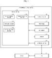
- Fig. 1 is a block diagram illustrating a configuration of a programmable display device 1 in accordance with Embodiment 1 of the present invention.
- the programmable display device 1 includes a control section 10, a display section 20, a touch panel 30, a user memory 40, a speaker 50, and an interface section 60.
- the programmable display device 1 is connected to a programmable logic controller (PLC) 2 via a communication cable, so as to be communicable with the PLC 2.
- PLC programmable logic controller
- the programmable display device 1 is a dedicated computer configured to display a graphics screen for operation and display to realize an operation function and a display function specific to the programmable display device.
- the programmable display device 1 is used as a human machine interface (HMI).
- HMI human machine interface
- the control section 10 identifies an action of displaying the status of a device 3 connected to the PLC 2 or an action of controlling the status of the device 3 in accordance with the operation carried out on the touch panel 30.
- the control section 10 controls each section of the programmable display device 1.
- the control section 10 includes a display control section 110, an obtaining section 130, a setting accepting section 140, and a process executing section 150.
- the display control section 110 causes the display section 20 to display a screen.
- the obtaining section 130 obtains, from the PLC 2, data related to the device 3.
- the setting accepting section 140 accepts a process setting concerning the data obtained by the obtaining section 130.
- the process executing section 150 executes a process in accordance with the process setting accepted by the setting accepting section 140.
- the process setting refers to configuring a setting concerning (a) the content of a process to be executed for the data obtained by the obtaining section 130 and (b) information for executing the process.
- the process setting includes configuring a new setting and reconfiguring the setting to change (edit) the already-set matter(s).
- the display section 20 displays a screen.
- the touch panel 30 accepts input operation that an end user has carried out on the display section 20.
- the user memory 40 stores information therein.
- the speaker 50 outputs audio to the outside of the programmable display device 1.
- the end user may simply be referred to as a "user", occasionally.
- the programmable display device 1 may incorporate an interface alone in place of the speaker 50. If the programmable display device 1 incorporates the interface alone, the speaker 50 is connected to the programmable display device 1 as an external device via the interface.
- the interface section 60 is a communication section via which the programmable display device 1 communicates with the PLC 2.
- the PLC 2 is a control device configured to read the status of the device 3 and/or provide a control instruction to the device 3 at predetermined scanning times in accordance with the sequential program prepared by a user.
- the device 3 may be a device controlled by the PLC 2, a device configured to output a value detected by a sensor, and/or the like. There are a plurality of such devices 3.
- the programmable display device 1 displays, via e.g. a screen and/or parts, the status of the device 3 obtained by the PLC 2.
- Fig. 2 is a view illustrating a display screen PI displayed on the display section 20, which is included in the programmable display device 1 shown in Fig. 1 .
- the display screen PI is shown as one example of the display screen displayed on the display section 20.
- the process related to the display screen PI described herein is also described as one example.
- the display control section 110 causes the display section 20 to display the display screen PI shown in Fig. 2 .
- the display screen PI includes a switch SW1, a numerical value indicator ND1, and a trend graph TG1.
- the switch SW1 is an object corresponding to one of the devices 3, and accepts operation for turning-ON/OFF, for example.
- the numerical value indicator ND1 is an object corresponding to one of the devices 3, and displays the numerical value of the latest data obtained by the obtaining section 130.
- the trend graph TG1 is an object corresponding to one of the devices 3, and indicates a graph of the values of the data obtained by the obtaining section 130 and accumulated in the user memory 40.
- the display control section 110 causes the display section 20 to display the switch SW1, the numerical value indicator ND1, and the trend graph TG1 as objects in this manner.
- Each object has a device address and/or a variable(s) specifying a place for storing data that the obtaining section 130 is to obtain from a device memory of the PLC 2.
- the user memory 40 stores therein data of plural display screens including the display screen PI.
- the user memory 40 accumulates therein data that the obtaining section 130 has obtained from the PLC 2 for the purpose of displaying the trend graph TG1.
- the display control section 110 causes the display section 20 to display a setting item list L1 concerning the numerical value indicator ND1.
- the setting item list L1 includes switching buttons B1, B2, and B3 and setting buttons B4, B5, and B6.
- the switching button B1 is a button used to switch between enabling and disabling of a logging function that is to be executed by the process executing section 150.
- the switching button B2 is a button used to switch between enabling and disabling of a notification function that is to be executed by the process executing section 150.
- the switching button B3 is a button used to switch between enabling and disabling of data analysis that is to be executed by the process executing section 150.
- the logging, notification, and data analysis that are to be executed by the process executing section 150 are examples of the content of the process to be executed for the data obtained by the obtaining section 130.
- the setting button B4 is a button used to cause the display section 20 to display a setting screen for configuring a setting concerning the logging function that is to be executed by the process executing section 150.
- the setting button B5 is a button used to cause the display section 20 to display a setting screen for configuring a setting concerning the notification function that is to be executed by the process executing section 150.
- the setting button B6 is a button used to cause the display section 20 to display a setting screen for configuring a setting concerning the data analysis that is to be executed by the process executing section 150.
- Fig. 3 is a view illustrating a setting screen SP1 displayed on the display section 20, which is included in the programmable display device 1 shown in Fig. 1 .
- the setting screen SP1 is one example of the setting screen displayed on the display section 20.
- the process concerning the setting screen SP1 described herein is also one example.
- the display control section 110 causes the display section 20 to display the setting screen SP1 for configuring a setting concerning the logging function that is to be executed by the process executing section 150.
- the setting screen SP1 is a screen for accepting a setting concerning the logging of data related to the numerical value indicator ND1.
- data indicating a numerical value concerning the numerical value indicator ND1 will be referred to as numerical data.
- the setting screen SP1 includes setting items SA1 to SA8, a cancel button C1, and an enter button E1.
- the setting item SA1 is an item for setting a cycle of executing logging of numerical data to the user memory 40.
- the setting item SA1 is provided based on the assumption that the process executing section 150 executes logging of numerical data to the user memory 40 in response to a trigger issued at a certain cycle, in a state where the user memory 40 can store the numerical data therein.
- the setting item SA2 is an item for setting the number of logs of numerical data that the process executing section 150 logs to the user memory 40.
- the setting item SA3 is an item for enabling or disabling the function in which the process executing section 150 overwrites the logs of the numerical data in the user memory 40 so as to keep updating the logs of the numerical data logged to the user memory 40.
- the process executing section 150 stops logging of the numerical data to the user memory 40 at the point of time when the number of logs of the numerical data logged to the user memory 40 reaches the number of logs having been set via the setting item SA2.
- the setting item SA4 is an item for setting the current time and for displaying the current time so that it can be referred to at the time of setting a starting date and time and an ending date and time.
- the setting item SA5 is an item for setting the date and time to start the logging of the numerical data that is to be carried out by the process executing section 150 with respect to the user memory 40.
- the setting item SA6 is an item for setting the date and time to end the logging of the numerical data that is to be carried out by the process executing section 150 with respect to the user memory 40.
- the setting item SA7 is an item for setting a file name of a file which is created by the process executing section 150 and in which the numerical data is accumulated.
- the process executing section 150 stores this file in the user memory 40.
- the setting item SA8 is an item for accepting a selection as to which of a first setting and a second setting is to be selected.
- first setting only numerical data obtained by the obtaining section 130 while the numerical value indicator ND1 is displayed on the display section 20 is specified as target data, which is numerical data that is to be subjected to the logging executed by the process executing section 150.
- second setting numerical data obtained by the obtaining section 130 while the obtaining section 130 is executing the obtaining of the numerical data is specified as the target data.
- the setting accepting section 140 detects the operation from the touch panel 30.
- the setting accepting section 140 accepts, via the setting screen SP1, a process setting configured via the setting items SA1 to SA8, which are included in the setting screen SP1.
- the process executing section 150 causes the process setting accepted by the setting accepting section 140 to be stored in the user memory 40 such that the process setting is associated with the numerical value indicator ND1.
- the display control section 110 causes the display section 20 to stop displaying the setting screen SP1, and causes the display section 20 to display the display screen PI.
- the display control section 110 causes the display section 20 to stop displaying the setting screen SP1, and causes the display section 20 to display the display screen PI.
- the setting accepting section 140 accepts, via the setting screen SP1 displayed in response to predetermined operation, a process setting concerning (a) the content of a process to be executed for the numerical data obtained by the obtaining section 130 and (b) information for executing the process.
- the setting accepting section 140 accepts the process setting in a state where the obtaining section 130 is executing the obtaining of the numerical data.
- the process executing section 150 executes the process including the content on the basis of the above information and in accordance with the process setting accepted by the setting accepting section 140.
- the process setting configured via the setting screen SP1 is accepted in a state where the obtaining section 130 is executing the obtaining of the numerical data. Consequently, the end user can easily configure the process setting via the setting screen SP1 by himself/herself, without the need to pay attention to a variable name and/or a device address. This can reduce the cost and time taken for the process setting.
- the above configuration enables the end user to configure the process setting by himself/herself, thereby eliminating the need to request an outside manufacturer or the like to configure the process setting.
- the above configuration eliminates the need for the outside manufacturer or the like to identify, among plural pieces of data, a piece(s) of data requiring a process setting before delivering the programmable display device 1 to the end user. Consequently, the outside manufacturer or the like can deliver the programmable display device 1 to the end user in a simple manner without various kinds of advance preparations.
- the setting accepting section 140 accepts, via the setting screen SP1, accumulation of the numerical data obtained by the obtaining section 130, the accumulation of the numerical data being accepted as the content of the process to be executed for the numerical data obtained by the obtaining section 130.
- the process executing section 150 executes, as the process to be executed for the numerical data, the accumulation of the numerical data accepted by the setting accepting section 140. Consequently, the end user can easily configure the process setting concerning the accumulation of the numerical data via the setting screen SP1.
- the setting accepting section 140 accepts, via the setting screen SP1, the selection as to which of the first setting and the second setting is to be selected, the selection being accepted as the process setting accepted by the setting accepting section 140.
- the process executing section 150 executes logging of only the numerical data obtained by the obtaining section 130 while the numerical value indicator ND1 is displayed on the display section 20.
- the process executing section 150 executes logging of the numerical data obtained by the obtaining section 130 while the obtaining section 130 is executing the obtaining of the numerical data.
- the amount of the numerical data that is to be subjected to the logging by the process executing section 150 is smaller than that of the case where the second setting is accepted, and thus the burden on the programmable display device 1 can be reduced.
- the amount of data to be collected can be changed according to the period of time to execute the logging.
- Fig. 4 is a view illustrating a setting screen SP2 that is not the setting screen SP1 shown in Fig. 3 .
- the display control section 110 causes the display section 20 to display a setting screen SP2 used to configure a setting concerning the notification function that is to be executed by the process executing section 150, as indicated by the reference sign 101 in Fig. 4 .
- the setting screen SP2 accepts a notification setting concerning the numerical value indicator ND1.
- the setting screen SP2 includes setting items SB1 to SB3, a reference button RB1, a cancel button C2, and an enter button E2.
- the setting item SB1 is an item for setting a predetermined condition.
- the process executing section 150 executes notification concerning the numerical value indicator ND1, if the predetermined condition on the numerical data concerning the numerical value indicator ND1 is satisfied.
- the notification may be an indication of an abnormality of the numerical value indicator ND1, for example.
- the predetermined condition is used as a condition for monitoring the numerical value indicator ND1.
- the setting item SB1 includes a plus button SBB, which is a button used to set a new condition in addition to the condition(s) having been set via the setting item SB1.
- the user can add a new condition by carrying out operation of touching the plus button SBB. Via the setting item SB1, it is possible to set AND, OR, and the like.
- the setting item SB2 is an item for setting a way to execute the notification concerning the numerical value indicator ND1.
- the way that can be set via the setting item SB2 may be an e-mail, audio output from the speaker 50, a buzzer, and/or color changing or flashing of the display screen PI, for example.
- the setting item SB3 is concerned with a setting content similar to that of the setting item SA8. However, the setting item SB3 is related to notification, rather than to the logging of the setting item SA8.
- the reference button RB1 is a button used to cause the display section 20 to display a result of data analysis executed by the process executing section 150.
- the display control section 110 Upon user operation of touching the reference button RB1, the display control section 110 causes the display section 20 to display a table T1, which indicates the result of the data analysis executed by the process executing section 150, as indicated by the reference sign 102 in Fig. 4 .
- the table T1 is one example of the result of the process having been executed by the process executing section 150.
- the table T1 includes, as examples of representative values of the numerical data calculated by the process executing section 150, a maximum value, a minimum value, and an average value of the numerical values of the logs of the numerical data as well as a maximum value, a minimum value, and an average value of the intervals between the logs of the numerical data. That is, the table T1 includes the information indicating the changes in the numerical values of the numerical data occurred until the process setting is configured via the setting screen SP2 as well as the information indicating the time intervals between the changes in the numerical values.
- the reference sign 102 in Fig. 4 indicates the table T1 showing the result of the data analysis.
- the table T1 may indicate a result obtained by any of other calculation methods and other analysis methods involving use of the numerical data accumulated in the user memory 40.
- the setting accepting section 140 accepts, via the setting screen SP2, the process setting configured via the setting items SB1 to SB3, which are included in the setting screen SP2.
- the process executing section 150 causes the user memory 40 to store therein the process setting accepted by the setting accepting section 140.
- the display control section 110 causes the display section 20 to stop displaying the setting screen SP2, and then causes the display section 20 to display the display screen PI.
- the display control section 110 causes the display section 20 to stop displaying the setting screen SP2, and then causes the display section 20 to display the display screen PI.
- the setting accepting section 140 accepts, as the content of the process to be executed for the numerical data obtained by the obtaining section 130, notification that is to be executed when a predetermined condition on the numerical data is satisfied.
- the setting accepting section 140 accepts the predetermined condition as the information for executing the process.
- the process executing section 150 executes the notification as the process to be executed for the numerical data obtained by the obtaining section 130, if the predetermined condition on the numerical data is satisfied. Consequently, the end user can easily configure the setting concerning the predetermined condition for the notification via the setting screen SP2.
- the process executing section 150 executes, as the process to be executed for the numerical data, the data analysis of analyzing the numerical data obtained by the obtaining section 130.
- the display control section 110 causes the display section 20 to display the setting screen SP2 in response to predetermined operation, and also causes the display section 20 to display the result of the process having been executed by the process executing section 150. In other words, the display control section 110 causes the display section 20 to display the result of the data analysis having been executed by the process executing section 150.
- the setting screen SP2 is displayed on the display section 20, and the result of the data analysis is also displayed on the display section 20. Therefore, the end user can easily configure the process setting via the setting screen SP2 while referring to the result of the data analysis.
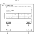
- Fig. 5 is a view illustrating a setting screen SP3 that is not the setting screen SP1 shown in Fig. 3 or the setting screen SP2 shown in Fig. 4 .
- the display control section 110 causes the display section 20 to display a setting screen SP3 used to configure a setting concerning the data analysis that is to be executed by the process executing section 150, as shown in Fig. 5 .
- the setting screen SP3 is a screen for accepting a setting concerning data analysis of numerical data related to the numerical value indicator ND1.
- the setting screen SP3 includes a setting item SC1, a table T2, a reference button RB3, a reset button RS1, a cancel button C3, and an enter button E3.
- the setting item SC1 is concerned with a setting content similar to that of the setting item SA8. However, the setting item SC1 is related to data analysis, rather than to the logging of the setting item SA8.
- a kind of a representative value that is to be set as the target data can be selected from among the kinds of the representative values of the numerical data included in the table T1.
- the display control section 110 causes the display section 20 to display a sign(s) indicating the selected one(s) of the kinds of the representative values.
- the process executing section 150 calculates only a representative value(s) of the kind(s) having been selected via the table T2, and the display control section 110 causes the display section 20 to display only the representative value(s) having been calculated by the process executing section 150.
- the reference button RB3 is a button used to cause the display section 20 to display a result of data analysis having been executed by the process executing section 150.
- the display control section 110 causes the display section 20 to display the table 1, which is described above.
- the reset button RS1 is a button used to reset the representative value(s) of the numerical data having been calculated by the process executing section 150 to zero.
- the process executing section 150 detects the operation from the touch panel 30, and resets the calculated representative value(s) of the numerical data to zero.
- the setting accepting section 140 accepts, via the setting screen SP3, the process setting configured via the setting item SC1, the table T2, and the reset button RS1 included in the setting screen SP3.
- the process executing section 150 causes the process setting accepted by the setting accepting section 140 to be stored in the user memory 40 such that the process setting is associated with the numerical value indicator ND1.
- the display control section 110 causes the display section 20 to stop displaying the setting screen SP3, and then causes the display section 20 to display the display screen PI.
- the display control section 110 causes the display section 20 to stop displaying the setting screen SP3, and then causes the display section 20 to display the display screen PI.
- the setting accepting section 140 accepts, via the setting screen SP3, data analysis of analyzing the numerical data obtained by the obtaining section 130, the data analysis being accepted as the content of the process to be executed for the numerical data obtained by the obtaining section 130.
- the process executing section 150 executes, as the process to be executed for the numerical data, the data analysis accepted by the setting accepting section 140.
- the setting accepting section 140 accepts the data analysis as the content of the process to be executed for the numerical data obtained by the obtaining section 130. Specifically, the setting accepting section 140 accepts, via the setting screen SP3, at least one kind of the representative values of the numerical data as the information for executing the process.
- the process executing section 150 calculates only the representative value of the kind accepted by the setting accepting section 140, and the display control section 110 causes the display section 20 to display only the representative value having been calculated by the process executing section 150. Consequently, the end user can cause the display section 20 to display only the necessary representative value by setting the kind of the representative value via the setting screen SP3.
- Fig. 6 is a view illustrating a display screen P2 displayed on a display section 20 included in a programmable display device 1 in accordance with Embodiment 2 of the present invention.
- a process executing section 150 refers to authentication information stored in a user memory 40 and executes an authentication process of authenticating the user.
- a display control section 110 causes the display section 20 to display the display screen P2 shown in Fig. 6 .
- the display screen P2 includes a user name UN and an authority level AL of the user authenticated by the process executing section 150.
- the user name, the authority level of the user, and the authentication information are preliminarily stored in association with each other.
- a setting accepting section 140 refers to the authority level of the user and the authentication information stored in the user memory 40, and determines, in accordance with the authority level of the user, whether to permit or inhibit a transition to the setting screen. Specifically, the setting accepting section 140 permits a transition to the setting screen, if the setting accepting section 140 determines that the authority level of the user is equal to or higher than a predetermined level. Meanwhile, the setting accepting section 140 inhibits a transition to the setting screen, if the setting accepting section 140 determines that the authority level of the user is lower than the predetermined level.
- the setting screen described herein refers to any of the setting screens SP1 to SP3 of Embodiment 1.
- the setting accepting section 140 determines that the authority level AL of the user is lower than the predetermined level in Fig. 6 .
- the setting accepting section 140 inhibits a transition to the setting screen and therefore the display control section 110 would not allow the display section 20 to display the setting item list L1.
- the display control section 110 may cause the display section 20 to display, by e.g. a pop-up screen, information indicating an operation error.
- This configuration makes it possible to prevent an erroneous operation and an erroneous setting made by a user who is not familiar with the device and equipment and does not have an authority.
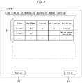
- Fig. 7 is a view illustrating a setting screen SP4 displayed on a display section 20 included in a programmable display device 1 in accordance with Embodiment 3 of the present invention.
- the display control section 110 causes the display section 20 to display a setting screen SP4.
- the setting screen SP4 includes a table T3.
- the table T3 includes items that can be set via the setting screens SP1 to SP3 of Embodiment 1. These items are listed in the table T3.
- the setting accepting section 140 switches between activation and deactivation of the data logging, notification, and data analysis.
- the table T3 shows whether the data logging, notification, and data analysis are activated or deactivated.
- the user can easily check, in a list, whether each of the data logging, notification, and data analysis is activated or deactivated by referring to the table T3. As a result, it is possible to avoid performance degradation that might otherwise be caused by unnecessary operation.
- the display control section 110 may cause the display section 20 to display a setting screen for the touched one of the items.
- icons indicating the items may be included in the setting screen SP4.
- the setting accepting section 140 accepts, via the setting screen SP4, the process setting configured via the table T3 included in the setting screen SP4.
- the process executing section 150 causes the user memory 40 to store therein the process setting accepted by the setting accepting section 140.
- the display control section 110 causes the display section 20 to stop displaying the setting screen SP4, and then causes the display section 20 to display the display screen PI.
- the display control section 110 causes the display section 20 to stop displaying the setting screen SP4, and then causes the display section 20 to display the display screen PI.
- the process executing section 150 may execute a process in which all of the process settings accepted by the setting accepting section 140 are stored in a project (a file including a series of the display screens) downloaded to the programmable display device 1.
- the process executing section 150 may execute a process in which, among the process settings, only a setting(s) being not a setting(s) already stored in the project is stored in the project.
- the setting accepting section 140 may accept, via the setting screen, a selection as to whether (a) all of the accepted process settings are to be stored in the project or (b) among the accepted process settings, only the setting(s) being not the setting(s) already stored in the project is to be stored in the project. Thanks to this configuration, the amount of the information of the process setting(s) to be stored in the project may be reduced. This can save time.
- the project described above is downloaded to the programmable display device 1 from an external device such as a personal computer (PC), and is then stored in the user memory 40.
- PC personal computer
- the process setting accepted by the setting accepting section 140 is applied also to another programmable display device 1.
- the process setting in the project By storing the process setting in the project and storing the project in a storage medium or the like, it is possible to easily reflect the process setting also to another programmable display device 1. This may sometimes reduce the amount of the information of the process settings. In such a case, it is possible to save the time taken for such a work. That is, if there exist devices of the same type and pieces of equipment of the same type, it is possible to manage the process settings as settings specific to one of the devices or pieces of equipment or to manage the process settings as common settings for the devices and the pieces of equipment and duplicate the process settings.
- Control blocks (the control section 10, specifically, the display control section 110, the obtaining section 130, the setting accepting section 140, and the process executing section 150) of the programmable display device 1 can be realized by a logic circuit (hardware) provided in an integrated circuit (IC chip) or the like or can be alternatively realized by software.
- the programmable display device 1 includes a computer that executes instructions of a program that is software realizing the foregoing functions.
- the computer for example, includes at least one processor and at least one computer-readable storage medium storing the program.
- An object of the present invention can be achieved by the processor of the computer reading and executing the program stored in the storage medium.
- the processor encompass a central processing unit (CPU).
- the storage medium encompass a "non-transitory tangible medium" such as a read only memory (ROM), a tape, a disk, a card, a semiconductor memory, and a programmable logic circuit.
- the computer may further include a random access memory (RAM) or the like in which the program is loaded.
- the program may be supplied to or made available to the computer via any transmission medium (such as a communication network and a broadcast wave) which allows the program to be transmitted.
- a transmission medium such as a communication network and a broadcast wave
- an aspect of the present invention can also be achieved in the form of a computer data signal in which the program is embodied via electronic transmission and which is embedded in a carrier wave.
- the present invention is not limited to the embodiments, but can be altered by a skilled person in the art within the scope of the claims.
- the present invention also encompasses, in its technical scope, any embodiment derived by combining technical means disclosed in differing embodiments.
- a programmable display device in accordance with an aspect of the present invention includes: an obtaining section configured to obtain data; a setting accepting section configured to accept a process setting via a setting screen displayed in response to predetermined operation, the process setting concerning (a) a content of a process to be executed for the data obtained by the obtaining section and (b) information for executing the process; and a process executing section configured to execute the process including the content, on the basis of the information and in accordance with the process setting accepted by the setting accepting section, the setting accepting section being further configured to accept the process setting in a state where the obtaining section is executing the obtaining of the data.
- the process setting configured via the setting screen is accepted in a state where the obtaining section is executing the obtaining of the data. Consequently, an end user can easily configure the process setting via the setting screen by himself/herself, without the need to pay attention to a variable name and/or a device address. This can reduce the cost and time taken for the process setting.
- the setting accepting section may be further configured to accept, via the setting screen, accumulation of the data obtained by the obtaining section, the accumulation of the data being accepted as the content; and the process executing section may be further configured to execute, as the process, the accumulation of the data accepted by the setting accepting section. Consequently, the end user can easily configure, via the setting screen, the process setting for the accumulation of the data.
- the setting accepting section may be further configured to accept, as the content, notification that is to be executed in a case where a predetermined condition on the data is satisfied, and the setting accepting section may be further configured to accept the predetermined condition as the information; and the process executing section may be further configured to execute the notification as the process, in a case where the predetermined condition on the data is satisfied. Consequently, the end user can easily configure, via the setting screen, the setting concerning the predetermined condition for the notification.
- the programmable display device may further include a display control section configured to cause a display section to display the setting screen in response to the predetermined operation, the display control section being further configured to cause the display section to display a result of the process having been executed by the process executing section, wherein: the setting accepting section may be further configured to accept, via the setting screen, data analysis of analyzing the data obtained by the obtaining section, the data analysis being accepted as the content; the process executing section may be further configured to execute, as the process, the data analysis having been accepted by the setting accepting section; and the display control section may be further configured to cause the display section to display a result of the data analysis having been executed by the process executing section.
- the end user can easily configure the process setting via the setting screen while referring to the result of the data analysis.
- the setting accepting section may be further configured to accept, via the setting screen, at least one kind of one or more representative values of the data as the information, in the case where the setting accepting section accepts the data analysis as the content; the process executing section may be further configured to calculate only a representative value of said at least one kind having been accepted by the setting accepting section; and the display control section is further configured to cause the display section to display only the representative value having been calculated by the process executing section.
- the end user can cause the display section to display only a necessary representative value by setting a kind of a representative value via the setting screen.
- the programmable display device may further include a display control section configured to cause a display section to display the setting screen in response to the predetermined operation, the display control section being further configured to cause the display section to display an object related to the data
- the setting accepting section is further configured to accept, via the setting screen, a selection as to which of a first setting or a second setting is to be selected, the selection being accepted as the process setting, the first setting specifying, as target data, only data obtained by the obtaining section while the object is displayed on the display section, the target data being the data that is to be subjected to the process executed by the process executing section, the second setting specifying, as the target data, data obtained by the obtaining section while the obtaining section is executing the obtaining of the data; and the process executing section is further configured to: execute the process only for the data obtained by the obtaining section while the object is displayed on the display section, in a case where the first setting is accepted by the setting accepting section; and to execute the process for the data obtained by the obtaining section while the obtaining
- the amount of the data that is to be subjected to the process to be carried out by the process executing section is smaller than that of the case where the second setting is accepted, and thus the burden on the programmable display device can be reduced.
- the amount of data to be collected can be changed according to the period of time to execute the process.
Landscapes
- Engineering & Computer Science (AREA)
- Physics & Mathematics (AREA)
- General Physics & Mathematics (AREA)
- Software Systems (AREA)
- Automation & Control Theory (AREA)
- Theoretical Computer Science (AREA)
- Human Computer Interaction (AREA)
- General Engineering & Computer Science (AREA)
- Programmable Controllers (AREA)
- User Interface Of Digital Computer (AREA)
Abstract
Description
- The present invention relates to a programmable display device.
-
Patent Literature 1 discloses a technique according to which a programmable display device sequentially displays, by display objects on a screen, statuses and circumstances of an input device and an output device on the basis of device data. This technique carries out logging of the device data according to logging setting information generated by a logging setting information generating device. In addition, according to the above technique, when a collection cycle setting is selected on a menu screen, a collection period setting section transmits a predetermined instruction to a display control section so as to cause a display section to display a setting screen via which collection cycle information can be input. -
Japanese Patent Application Publication Tokukai No. 2011-28496 - However, the technique disclosed in
Patent Literature 1 does not assume a situation in which an end user of the programmable display device attached to a device configures and/or changes a setting of logging or the like in the programmable display device. If there arises a need to configure and/or change the setting of logging or the like in the programmable display device, the end user needs to request an outside manufacturer or the like that has designed the device to configure and/change the setting. Thus, the technique disclosed inPatent Literature 1 takes much cost and time to configure and/or change the setting, disadvantageously. An aspect of the present invention has an object to reduce the cost and time taken to configure a process setting for a programmable display device. - In order to attain the object, a programmable display device in accordance with an aspect of the present invention includes: an obtaining section configured to obtain data; a setting accepting section configured to accept a process setting via a setting screen displayed in response to predetermined operation, the process setting concerning (a) a content of a process to be executed for the data obtained by the obtaining section and (b) information for executing the process; and a process executing section configured to execute the process including the content, on the basis of the information and in accordance with the process setting accepted by the setting accepting section, the setting accepting section being further configured to accept the process setting in a state where the obtaining section is executing the obtaining of the data.
- According to an aspect of the present invention, it is possible to reduce the cost and time taken to configure the process setting of the programmable display device.
-
-
Fig. 1 Fig. 1 is a block diagram illustrating a configuration of a programmable display device in accordance withEmbodiment 1 of the present invention. -
Fig. 2 Fig. 2 is a view illustrating a display screen displayed on a display section included in the programmable display device shown inFig. 1 . -
Fig. 3 Fig. 3 is a view illustrating a setting screen displayed on the display section included in the programmable display device shown inFig. 1 . -
Fig. 4 Fig. 4 is a view illustrating a setting screen that is not the setting screen shown inFig. 3 . -
Fig. 5 Fig. 5 is a view illustrating a setting screen that is not the setting screen shown inFig. 3 or the setting screen shown inFig. 4 . -
Fig. 6 Fig. 6 is a view illustrating a display screen displayed on a display section included in a programmable display device in accordance withEmbodiment 2 of the present invention. -
Fig. 7 Fig. 7 is a view illustrating a setting screen displayed on a display section included in a programmable display device in accordance withEmbodiment 3 of the present invention. -
Fig. 1 is a block diagram illustrating a configuration of aprogrammable display device 1 in accordance withEmbodiment 1 of the present invention. As shown inFig. 1 , theprogrammable display device 1 includes acontrol section 10, adisplay section 20, atouch panel 30, auser memory 40, aspeaker 50, and aninterface section 60. - The
programmable display device 1 is connected to a programmable logic controller (PLC) 2 via a communication cable, so as to be communicable with thePLC 2. Theprogrammable display device 1 is a dedicated computer configured to display a graphics screen for operation and display to realize an operation function and a display function specific to the programmable display device. Theprogrammable display device 1 is used as a human machine interface (HMI). - The
control section 10 identifies an action of displaying the status of adevice 3 connected to thePLC 2 or an action of controlling the status of thedevice 3 in accordance with the operation carried out on thetouch panel 30. Thecontrol section 10 controls each section of theprogrammable display device 1. Thecontrol section 10 includes adisplay control section 110, an obtainingsection 130, asetting accepting section 140, and aprocess executing section 150. - The
display control section 110 causes thedisplay section 20 to display a screen. The obtainingsection 130 obtains, from thePLC 2, data related to thedevice 3. Thesetting accepting section 140 accepts a process setting concerning the data obtained by the obtainingsection 130. Theprocess executing section 150 executes a process in accordance with the process setting accepted by thesetting accepting section 140. - Here, the process setting refers to configuring a setting concerning (a) the content of a process to be executed for the data obtained by the obtaining
section 130 and (b) information for executing the process. To be more specific, the process setting includes configuring a new setting and reconfiguring the setting to change (edit) the already-set matter(s). - The
display section 20 displays a screen. Thetouch panel 30 accepts input operation that an end user has carried out on thedisplay section 20. Theuser memory 40 stores information therein. Thespeaker 50 outputs audio to the outside of theprogrammable display device 1. Hereinafter, the end user may simply be referred to as a "user", occasionally. - Note that the
programmable display device 1 may incorporate an interface alone in place of thespeaker 50. If theprogrammable display device 1 incorporates the interface alone, thespeaker 50 is connected to theprogrammable display device 1 as an external device via the interface. Theinterface section 60 is a communication section via which theprogrammable display device 1 communicates with thePLC 2. - The
PLC 2 is a control device configured to read the status of thedevice 3 and/or provide a control instruction to thedevice 3 at predetermined scanning times in accordance with the sequential program prepared by a user. Thedevice 3 may be a device controlled by thePLC 2, a device configured to output a value detected by a sensor, and/or the like. There are a plurality ofsuch devices 3. Theprogrammable display device 1 displays, via e.g. a screen and/or parts, the status of thedevice 3 obtained by thePLC 2. -
Fig. 2 is a view illustrating a display screen PI displayed on thedisplay section 20, which is included in theprogrammable display device 1 shown inFig. 1 . The display screen PI is shown as one example of the display screen displayed on thedisplay section 20. The process related to the display screen PI described herein is also described as one example. Thedisplay control section 110 causes thedisplay section 20 to display the display screen PI shown inFig. 2 . - The display screen PI includes a switch SW1, a numerical value indicator ND1, and a trend graph TG1. The switch SW1 is an object corresponding to one of the
devices 3, and accepts operation for turning-ON/OFF, for example. The numerical value indicator ND1 is an object corresponding to one of thedevices 3, and displays the numerical value of the latest data obtained by the obtainingsection 130. The trend graph TG1 is an object corresponding to one of thedevices 3, and indicates a graph of the values of the data obtained by the obtainingsection 130 and accumulated in theuser memory 40. - The
display control section 110 causes thedisplay section 20 to display the switch SW1, the numerical value indicator ND1, and the trend graph TG1 as objects in this manner. Each object has a device address and/or a variable(s) specifying a place for storing data that the obtainingsection 130 is to obtain from a device memory of thePLC 2. - The
user memory 40 stores therein data of plural display screens including the display screen PI. Theuser memory 40 accumulates therein data that the obtainingsection 130 has obtained from thePLC 2 for the purpose of displaying the trend graph TG1. - When the user carries out predetermined operation such as pressing and holding the numerical value indicator ND1 on the display screen PI, the
display control section 110 causes thedisplay section 20 to display a setting item list L1 concerning the numerical value indicator ND1. The setting item list L1 includes switching buttons B1, B2, and B3 and setting buttons B4, B5, and B6. - The switching button B1 is a button used to switch between enabling and disabling of a logging function that is to be executed by the
process executing section 150. The switching button B2 is a button used to switch between enabling and disabling of a notification function that is to be executed by theprocess executing section 150. The switching button B3 is a button used to switch between enabling and disabling of data analysis that is to be executed by theprocess executing section 150. The logging, notification, and data analysis that are to be executed by theprocess executing section 150 are examples of the content of the process to be executed for the data obtained by the obtainingsection 130. - The setting button B4 is a button used to cause the
display section 20 to display a setting screen for configuring a setting concerning the logging function that is to be executed by theprocess executing section 150. The setting button B5 is a button used to cause thedisplay section 20 to display a setting screen for configuring a setting concerning the notification function that is to be executed by theprocess executing section 150. The setting button B6 is a button used to cause thedisplay section 20 to display a setting screen for configuring a setting concerning the data analysis that is to be executed by theprocess executing section 150. -
Fig. 3 is a view illustrating a setting screen SP1 displayed on thedisplay section 20, which is included in theprogrammable display device 1 shown inFig. 1 . The setting screen SP1 is one example of the setting screen displayed on thedisplay section 20. The process concerning the setting screen SP1 described herein is also one example. In response to user operation of touching the setting button B4 on the display screen PI, thedisplay control section 110 causes thedisplay section 20 to display the setting screen SP1 for configuring a setting concerning the logging function that is to be executed by theprocess executing section 150. - The setting screen SP1 is a screen for accepting a setting concerning the logging of data related to the numerical value indicator ND1. Hereinafter, data indicating a numerical value concerning the numerical value indicator ND1 will be referred to as numerical data. The setting screen SP1 includes setting items SA1 to SA8, a cancel button C1, and an enter button E1.
- The setting item SA1 is an item for setting a cycle of executing logging of numerical data to the
user memory 40. The setting item SA1 is provided based on the assumption that theprocess executing section 150 executes logging of numerical data to theuser memory 40 in response to a trigger issued at a certain cycle, in a state where theuser memory 40 can store the numerical data therein. The setting item SA2 is an item for setting the number of logs of numerical data that theprocess executing section 150 logs to theuser memory 40. - The setting item SA3 is an item for enabling or disabling the function in which the
process executing section 150 overwrites the logs of the numerical data in theuser memory 40 so as to keep updating the logs of the numerical data logged to theuser memory 40. In a case where the function that can be set via setting item SA3 is disabled, theprocess executing section 150 stops logging of the numerical data to theuser memory 40 at the point of time when the number of logs of the numerical data logged to theuser memory 40 reaches the number of logs having been set via the setting item SA2. - The setting item SA4 is an item for setting the current time and for displaying the current time so that it can be referred to at the time of setting a starting date and time and an ending date and time. The setting item SA5 is an item for setting the date and time to start the logging of the numerical data that is to be carried out by the
process executing section 150 with respect to theuser memory 40. The setting item SA6 is an item for setting the date and time to end the logging of the numerical data that is to be carried out by theprocess executing section 150 with respect to theuser memory 40. - The setting item SA7 is an item for setting a file name of a file which is created by the
process executing section 150 and in which the numerical data is accumulated. Theprocess executing section 150 stores this file in theuser memory 40. - The setting item SA8 is an item for accepting a selection as to which of a first setting and a second setting is to be selected. In the first setting, only numerical data obtained by the obtaining
section 130 while the numerical value indicator ND1 is displayed on thedisplay section 20 is specified as target data, which is numerical data that is to be subjected to the logging executed by theprocess executing section 150. In the second setting, numerical data obtained by the obtainingsection 130 while the obtainingsection 130 is executing the obtaining of the numerical data is specified as the target data. - When the user carries out operation of touching the enter button E1 on the setting screen SP1, the
setting accepting section 140 detects the operation from thetouch panel 30. Thesetting accepting section 140 accepts, via the setting screen SP1, a process setting configured via the setting items SA1 to SA8, which are included in the setting screen SP1. Theprocess executing section 150 causes the process setting accepted by thesetting accepting section 140 to be stored in theuser memory 40 such that the process setting is associated with the numerical value indicator ND1. Thedisplay control section 110 causes thedisplay section 20 to stop displaying the setting screen SP1, and causes thedisplay section 20 to display the display screen PI. - Meanwhile, when the user carries out operation of touching the cancel button C1 on the setting screen SP1, the
display control section 110 causes thedisplay section 20 to stop displaying the setting screen SP1, and causes thedisplay section 20 to display the display screen PI. - As described above, the
setting accepting section 140 accepts, via the setting screen SP1 displayed in response to predetermined operation, a process setting concerning (a) the content of a process to be executed for the numerical data obtained by the obtainingsection 130 and (b) information for executing the process. Thesetting accepting section 140 accepts the process setting in a state where the obtainingsection 130 is executing the obtaining of the numerical data. Theprocess executing section 150 executes the process including the content on the basis of the above information and in accordance with the process setting accepted by thesetting accepting section 140. - The process setting configured via the setting screen SP1 is accepted in a state where the obtaining
section 130 is executing the obtaining of the numerical data. Consequently, the end user can easily configure the process setting via the setting screen SP1 by himself/herself, without the need to pay attention to a variable name and/or a device address. This can reduce the cost and time taken for the process setting. - Furthermore, the above configuration enables the end user to configure the process setting by himself/herself, thereby eliminating the need to request an outside manufacturer or the like to configure the process setting. In addition, the above configuration eliminates the need for the outside manufacturer or the like to identify, among plural pieces of data, a piece(s) of data requiring a process setting before delivering the
programmable display device 1 to the end user. Consequently, the outside manufacturer or the like can deliver theprogrammable display device 1 to the end user in a simple manner without various kinds of advance preparations. - The configuration shown in
Fig. 3 will be further described. Specifically, thesetting accepting section 140 accepts, via the setting screen SP1, accumulation of the numerical data obtained by the obtainingsection 130, the accumulation of the numerical data being accepted as the content of the process to be executed for the numerical data obtained by the obtainingsection 130. Theprocess executing section 150 executes, as the process to be executed for the numerical data, the accumulation of the numerical data accepted by thesetting accepting section 140. Consequently, the end user can easily configure the process setting concerning the accumulation of the numerical data via the setting screen SP1. - In addition, the
setting accepting section 140 accepts, via the setting screen SP1, the selection as to which of the first setting and the second setting is to be selected, the selection being accepted as the process setting accepted by thesetting accepting section 140. In a case where the first setting is accepted by thesetting accepting section 140, theprocess executing section 150 executes logging of only the numerical data obtained by the obtainingsection 130 while the numerical value indicator ND1 is displayed on thedisplay section 20. In a case where the second setting is accepted by thesetting accepting section 140, theprocess executing section 150 executes logging of the numerical data obtained by the obtainingsection 130 while the obtainingsection 130 is executing the obtaining of the numerical data. - In the case where the first setting is accepted by the
setting accepting section 140, the amount of the numerical data that is to be subjected to the logging by theprocess executing section 150 is smaller than that of the case where the second setting is accepted, and thus the burden on theprogrammable display device 1 can be reduced. In addition, since the above configuration enables the end user to switch between the first setting and the second setting, the amount of data to be collected can be changed according to the period of time to execute the logging. -
Fig. 4 is a view illustrating a setting screen SP2 that is not the setting screen SP1 shown inFig. 3 . In response to user operation of touching the setting button B5 on the display screen PI shown inFig. 2 , thedisplay control section 110 causes thedisplay section 20 to display a setting screen SP2 used to configure a setting concerning the notification function that is to be executed by theprocess executing section 150, as indicated by thereference sign 101 inFig. 4 . The setting screen SP2 accepts a notification setting concerning the numerical value indicator ND1. The setting screen SP2 includes setting items SB1 to SB3, a reference button RB1, a cancel button C2, and an enter button E2. - The setting item SB1 is an item for setting a predetermined condition. The
process executing section 150 executes notification concerning the numerical value indicator ND1, if the predetermined condition on the numerical data concerning the numerical value indicator ND1 is satisfied. The notification may be an indication of an abnormality of the numerical value indicator ND1, for example. Via the setting item SB1, it is possible to set the predetermined condition. The predetermined condition is used as a condition for monitoring the numerical value indicator ND1. - The setting item SB1 includes a plus button SBB, which is a button used to set a new condition in addition to the condition(s) having been set via the setting item SB1. The user can add a new condition by carrying out operation of touching the plus button SBB. Via the setting item SB1, it is possible to set AND, OR, and the like.
- The setting item SB2 is an item for setting a way to execute the notification concerning the numerical value indicator ND1. The way that can be set via the setting item SB2 may be an e-mail, audio output from the
speaker 50, a buzzer, and/or color changing or flashing of the display screen PI, for example. The setting item SB3 is concerned with a setting content similar to that of the setting item SA8. However, the setting item SB3 is related to notification, rather than to the logging of the setting item SA8. - The reference button RB1 is a button used to cause the
display section 20 to display a result of data analysis executed by theprocess executing section 150. Upon user operation of touching the reference button RB1, thedisplay control section 110 causes thedisplay section 20 to display a table T1, which indicates the result of the data analysis executed by theprocess executing section 150, as indicated by thereference sign 102 inFig. 4 . The table T1 is one example of the result of the process having been executed by theprocess executing section 150. - The table T1 includes, as examples of representative values of the numerical data calculated by the
process executing section 150, a maximum value, a minimum value, and an average value of the numerical values of the logs of the numerical data as well as a maximum value, a minimum value, and an average value of the intervals between the logs of the numerical data. That is, the table T1 includes the information indicating the changes in the numerical values of the numerical data occurred until the process setting is configured via the setting screen SP2 as well as the information indicating the time intervals between the changes in the numerical values. - The
reference sign 102 inFig. 4 indicates the table T1 showing the result of the data analysis. However, this is not limitative. Alternatively, the table T1 may indicate a result obtained by any of other calculation methods and other analysis methods involving use of the numerical data accumulated in theuser memory 40. Upon user operation of touching an omission button RB2, thedisplay control section 110 causes thedisplay section 20 to stop displaying the result of the data analysis. - When the user carries out operation of touching the enter button E2 on the setting screen SP2, the
setting accepting section 140 accepts, via the setting screen SP2, the process setting configured via the setting items SB1 to SB3, which are included in the setting screen SP2. Theprocess executing section 150 causes theuser memory 40 to store therein the process setting accepted by thesetting accepting section 140. Thedisplay control section 110 causes thedisplay section 20 to stop displaying the setting screen SP2, and then causes thedisplay section 20 to display the display screen PI. - Meanwhile, when the user carries out operation of touching the cancel button C2 on the setting screen SP2, the
display control section 110 causes thedisplay section 20 to stop displaying the setting screen SP2, and then causes thedisplay section 20 to display the display screen PI. - As described above, the
setting accepting section 140 accepts, as the content of the process to be executed for the numerical data obtained by the obtainingsection 130, notification that is to be executed when a predetermined condition on the numerical data is satisfied. Thesetting accepting section 140 accepts the predetermined condition as the information for executing the process. - In addition, the
process executing section 150 executes the notification as the process to be executed for the numerical data obtained by the obtainingsection 130, if the predetermined condition on the numerical data is satisfied. Consequently, the end user can easily configure the setting concerning the predetermined condition for the notification via the setting screen SP2. - Furthermore, the
process executing section 150 executes, as the process to be executed for the numerical data, the data analysis of analyzing the numerical data obtained by the obtainingsection 130. Thedisplay control section 110 causes thedisplay section 20 to display the setting screen SP2 in response to predetermined operation, and also causes thedisplay section 20 to display the result of the process having been executed by theprocess executing section 150. In other words, thedisplay control section 110 causes thedisplay section 20 to display the result of the data analysis having been executed by theprocess executing section 150. - Consequently, the setting screen SP2 is displayed on the
display section 20, and the result of the data analysis is also displayed on thedisplay section 20. Therefore, the end user can easily configure the process setting via the setting screen SP2 while referring to the result of the data analysis. -
Fig. 5 is a view illustrating a setting screen SP3 that is not the setting screen SP1 shown inFig. 3 or the setting screen SP2 shown inFig. 4 . In response to user operation of touching the setting button B6 on the display screen PI shown inFig. 2 , thedisplay control section 110 causes thedisplay section 20 to display a setting screen SP3 used to configure a setting concerning the data analysis that is to be executed by theprocess executing section 150, as shown inFig. 5 . - The setting screen SP3 is a screen for accepting a setting concerning data analysis of numerical data related to the numerical value indicator ND1. The setting screen SP3 includes a setting item SC1, a table T2, a reference button RB3, a reset button RS1, a cancel button C3, and an enter button E3. The setting item SC1 is concerned with a setting content similar to that of the setting item SA8. However, the setting item SC1 is related to data analysis, rather than to the logging of the setting item SA8.
- Via the table T2, a kind of a representative value that is to be set as the target data can be selected from among the kinds of the representative values of the numerical data included in the table T1. Upon user operation of touching one(s) of the kinds of the representative values included in the table T2, the
display control section 110 causes thedisplay section 20 to display a sign(s) indicating the selected one(s) of the kinds of the representative values. Theprocess executing section 150 calculates only a representative value(s) of the kind(s) having been selected via the table T2, and thedisplay control section 110 causes thedisplay section 20 to display only the representative value(s) having been calculated by theprocess executing section 150. - Similarly to the reference button RB1, the reference button RB3 is a button used to cause the
display section 20 to display a result of data analysis having been executed by theprocess executing section 150. Upon user operation of touching the reference button RB3, thedisplay control section 110 causes thedisplay section 20 to display the table 1, which is described above. - The reset button RS1 is a button used to reset the representative value(s) of the numerical data having been calculated by the
process executing section 150 to zero. When the user carries out operation of touching the reset button RS1, theprocess executing section 150 detects the operation from thetouch panel 30, and resets the calculated representative value(s) of the numerical data to zero. - When the user carries out operation of touching the enter button E3 on the setting screen SP3, the
setting accepting section 140 accepts, via the setting screen SP3, the process setting configured via the setting item SC1, the table T2, and the reset button RS1 included in the setting screen SP3. Theprocess executing section 150 causes the process setting accepted by thesetting accepting section 140 to be stored in theuser memory 40 such that the process setting is associated with the numerical value indicator ND1. Thedisplay control section 110 causes thedisplay section 20 to stop displaying the setting screen SP3, and then causes thedisplay section 20 to display the display screen PI. - Meanwhile, when the user carries out operation of touching the cancel button C3 on the setting screen SP3, the
display control section 110 causes thedisplay section 20 to stop displaying the setting screen SP3, and then causes thedisplay section 20 to display the display screen PI. - As described above, the
setting accepting section 140 accepts, via the setting screen SP3, data analysis of analyzing the numerical data obtained by the obtainingsection 130, the data analysis being accepted as the content of the process to be executed for the numerical data obtained by the obtainingsection 130. Theprocess executing section 150 executes, as the process to be executed for the numerical data, the data analysis accepted by thesetting accepting section 140. - Furthermore, the
setting accepting section 140 accepts the data analysis as the content of the process to be executed for the numerical data obtained by the obtainingsection 130. Specifically, thesetting accepting section 140 accepts, via the setting screen SP3, at least one kind of the representative values of the numerical data as the information for executing the process. - The
process executing section 150 calculates only the representative value of the kind accepted by thesetting accepting section 140, and thedisplay control section 110 causes thedisplay section 20 to display only the representative value having been calculated by theprocess executing section 150. Consequently, the end user can cause thedisplay section 20 to display only the necessary representative value by setting the kind of the representative value via the setting screen SP3. - The following will describe
Embodiment 2 of the present invention. For convenience of description, members having functions identical to those described inEmbodiment 1 are assigned identical referential numerals, and their descriptions are omitted here.Fig. 6 is a view illustrating a display screen P2 displayed on adisplay section 20 included in aprogrammable display device 1 in accordance withEmbodiment 2 of the present invention. - The following will explain a case where, in response to user input operation carried out on the
display section 20 of theprogrammable display device 1, aprocess executing section 150 refers to authentication information stored in auser memory 40 and executes an authentication process of authenticating the user. In this case, if the user is authenticated by theprocess executing section 150, adisplay control section 110 causes thedisplay section 20 to display the display screen P2 shown inFig. 6 . - The display screen P2 includes a user name UN and an authority level AL of the user authenticated by the
process executing section 150. In theuser memory 40, the user name, the authority level of the user, and the authentication information are preliminarily stored in association with each other. - A
setting accepting section 140 refers to the authority level of the user and the authentication information stored in theuser memory 40, and determines, in accordance with the authority level of the user, whether to permit or inhibit a transition to the setting screen. Specifically, thesetting accepting section 140 permits a transition to the setting screen, if thesetting accepting section 140 determines that the authority level of the user is equal to or higher than a predetermined level. Meanwhile, thesetting accepting section 140 inhibits a transition to the setting screen, if thesetting accepting section 140 determines that the authority level of the user is lower than the predetermined level. The setting screen described herein refers to any of the setting screens SP1 to SP3 ofEmbodiment 1. - The following will explain a case where the
setting accepting section 140 determines that the authority level AL of the user is lower than the predetermined level inFig. 6 . In this case, even when the user carries out predetermined operation such as pressing and holding the numerical value indicator ND1 on the display screen P2, thesetting accepting section 140 inhibits a transition to the setting screen and therefore thedisplay control section 110 would not allow thedisplay section 20 to display the setting item list L1. - In this case, the
display control section 110 may cause thedisplay section 20 to display, by e.g. a pop-up screen, information indicating an operation error. This configuration makes it possible to prevent an erroneous operation and an erroneous setting made by a user who is not familiar with the device and equipment and does not have an authority. - The following will describe
Embodiment 3 of the present invention. For convenience of description, members having functions identical to those described inEmbodiment 1 are assigned identical referential numerals, and their descriptions are omitted here.Fig. 7 is a view illustrating a setting screen SP4 displayed on adisplay section 20 included in aprogrammable display device 1 in accordance withEmbodiment 3 of the present invention. - If predetermined operation is carried out on the display screen PI shown in
Fig. 2 after an obtainingsection 130 has started obtaining of data, thedisplay control section 110 causes thedisplay section 20 to display a setting screen SP4. The setting screen SP4 includes a table T3. The table T3 includes items that can be set via the setting screens SP1 to SP3 ofEmbodiment 1. These items are listed in the table T3. - In response to user operation of touching the items in the table T3, the
setting accepting section 140 switches between activation and deactivation of the data logging, notification, and data analysis. The table T3 shows whether the data logging, notification, and data analysis are activated or deactivated. - Consequently, the user can easily check, in a list, whether each of the data logging, notification, and data analysis is activated or deactivated by referring to the table T3. As a result, it is possible to avoid performance degradation that might otherwise be caused by unnecessary operation. In addition, in response to user operation of touching one of the items in the table T3, the
display control section 110 may cause thedisplay section 20 to display a setting screen for the touched one of the items. Furthermore, in place of the table T3, icons indicating the items may be included in the setting screen SP4. - When the user carries out operation of touching the enter button E4 on the setting screen SP4, the
setting accepting section 140 accepts, via the setting screen SP4, the process setting configured via the table T3 included in the setting screen SP4. Theprocess executing section 150 causes theuser memory 40 to store therein the process setting accepted by thesetting accepting section 140. Thedisplay control section 110 causes thedisplay section 20 to stop displaying the setting screen SP4, and then causes thedisplay section 20 to display the display screen PI. - Meanwhile, when the user carries out operation of touching the cancel button C4 on the setting screen SP4, the
display control section 110 causes thedisplay section 20 to stop displaying the setting screen SP4, and then causes thedisplay section 20 to display the display screen PI. - Note that, after the obtaining
section 130 has started obtaining of the numerical data, theprocess executing section 150 may execute a process in which all of the process settings accepted by thesetting accepting section 140 are stored in a project (a file including a series of the display screens) downloaded to theprogrammable display device 1. Alternatively, theprocess executing section 150 may execute a process in which, among the process settings, only a setting(s) being not a setting(s) already stored in the project is stored in the project. - In the case where the above process is carried out, the
setting accepting section 140 may accept, via the setting screen, a selection as to whether (a) all of the accepted process settings are to be stored in the project or (b) among the accepted process settings, only the setting(s) being not the setting(s) already stored in the project is to be stored in the project. Thanks to this configuration, the amount of the information of the process setting(s) to be stored in the project may be reduced. This can save time. The project described above is downloaded to theprogrammable display device 1 from an external device such as a personal computer (PC), and is then stored in theuser memory 40. - The following will explain a case where the process setting accepted by the
setting accepting section 140 is applied also to anotherprogrammable display device 1. By storing the process setting in the project and storing the project in a storage medium or the like, it is possible to easily reflect the process setting also to anotherprogrammable display device 1. This may sometimes reduce the amount of the information of the process settings. In such a case, it is possible to save the time taken for such a work. That is, if there exist devices of the same type and pieces of equipment of the same type, it is possible to manage the process settings as settings specific to one of the devices or pieces of equipment or to manage the process settings as common settings for the devices and the pieces of equipment and duplicate the process settings. - Control blocks (the
control section 10, specifically, thedisplay control section 110, the obtainingsection 130, thesetting accepting section 140, and the process executing section 150) of theprogrammable display device 1 can be realized by a logic circuit (hardware) provided in an integrated circuit (IC chip) or the like or can be alternatively realized by software. - In the latter case, the
programmable display device 1 includes a computer that executes instructions of a program that is software realizing the foregoing functions. The computer, for example, includes at least one processor and at least one computer-readable storage medium storing the program. An object of the present invention can be achieved by the processor of the computer reading and executing the program stored in the storage medium. Examples of the processor encompass a central processing unit (CPU). Examples of the storage medium encompass a "non-transitory tangible medium" such as a read only memory (ROM), a tape, a disk, a card, a semiconductor memory, and a programmable logic circuit. The computer may further include a random access memory (RAM) or the like in which the program is loaded. Further, the program may be supplied to or made available to the computer via any transmission medium (such as a communication network and a broadcast wave) which allows the program to be transmitted. Note that an aspect of the present invention can also be achieved in the form of a computer data signal in which the program is embodied via electronic transmission and which is embedded in a carrier wave. - The present invention is not limited to the embodiments, but can be altered by a skilled person in the art within the scope of the claims. The present invention also encompasses, in its technical scope, any embodiment derived by combining technical means disclosed in differing embodiments.
- Aspects of the present invention can also be expressed as follows:
A programmable display device in accordance with an aspect of the present invention includes: an obtaining section configured to obtain data; a setting accepting section configured to accept a process setting via a setting screen displayed in response to predetermined operation, the process setting concerning (a) a content of a process to be executed for the data obtained by the obtaining section and (b) information for executing the process; and a process executing section configured to execute the process including the content, on the basis of the information and in accordance with the process setting accepted by the setting accepting section, the setting accepting section being further configured to accept the process setting in a state where the obtaining section is executing the obtaining of the data. - The process setting configured via the setting screen is accepted in a state where the obtaining section is executing the obtaining of the data. Consequently, an end user can easily configure the process setting via the setting screen by himself/herself, without the need to pay attention to a variable name and/or a device address. This can reduce the cost and time taken for the process setting.
- The setting accepting section may be further configured to accept, via the setting screen, accumulation of the data obtained by the obtaining section, the accumulation of the data being accepted as the content; and the process executing section may be further configured to execute, as the process, the accumulation of the data accepted by the setting accepting section. Consequently, the end user can easily configure, via the setting screen, the process setting for the accumulation of the data.
- The setting accepting section may be further configured to accept, as the content, notification that is to be executed in a case where a predetermined condition on the data is satisfied, and the setting accepting section may be further configured to accept the predetermined condition as the information; and the process executing section may be further configured to execute the notification as the process, in a case where the predetermined condition on the data is satisfied. Consequently, the end user can easily configure, via the setting screen, the setting concerning the predetermined condition for the notification.
- The programmable display device may further include a display control section configured to cause a display section to display the setting screen in response to the predetermined operation, the display control section being further configured to cause the display section to display a result of the process having been executed by the process executing section, wherein: the setting accepting section may be further configured to accept, via the setting screen, data analysis of analyzing the data obtained by the obtaining section, the data analysis being accepted as the content; the process executing section may be further configured to execute, as the process, the data analysis having been accepted by the setting accepting section; and the display control section may be further configured to cause the display section to display a result of the data analysis having been executed by the process executing section.
- Since the setting screen is displayed on the display section and the result of the data analysis is also displayed on the display section, the end user can easily configure the process setting via the setting screen while referring to the result of the data analysis.
- The setting accepting section may be further configured to accept, via the setting screen, at least one kind of one or more representative values of the data as the information, in the case where the setting accepting section accepts the data analysis as the content; the process executing section may be further configured to calculate only a representative value of said at least one kind having been accepted by the setting accepting section; and the display control section is further configured to cause the display section to display only the representative value having been calculated by the process executing section. The end user can cause the display section to display only a necessary representative value by setting a kind of a representative value via the setting screen.
- The programmable display device may further include a display control section configured to cause a display section to display the setting screen in response to the predetermined operation, the display control section being further configured to cause the display section to display an object related to the data, wherein: the setting accepting section is further configured to accept, via the setting screen, a selection as to which of a first setting or a second setting is to be selected, the selection being accepted as the process setting, the first setting specifying, as target data, only data obtained by the obtaining section while the object is displayed on the display section, the target data being the data that is to be subjected to the process executed by the process executing section, the second setting specifying, as the target data, data obtained by the obtaining section while the obtaining section is executing the obtaining of the data; and the process executing section is further configured to: execute the process only for the data obtained by the obtaining section while the object is displayed on the display section, in a case where the first setting is accepted by the setting accepting section; and to execute the process for the data obtained by the obtaining section while the obtaining section is executing the obtaining of the data, in a case where the second setting is accepted by the setting accepting section.
- In the case where the first setting is accepted by the setting accepting section, the amount of the data that is to be subjected to the process to be carried out by the process executing section is smaller than that of the case where the second setting is accepted, and thus the burden on the programmable display device can be reduced. In addition, since the above configuration enables the end user to switch between the first setting and the second setting, the amount of data to be collected can be changed according to the period of time to execute the process.
-
- 1
- Programmable display device
- 20
- Display section
- 110
- Display control section
- 130
- Obtaining section
- 140
- Setting accepting section
- 150
- Process executing section
- ND1
- Numerical value indicator (object)
- SW1
- Switch (object)
- TG1
- Trend graph (object)
- SP1 to SP4
- Setting screen
Claims (6)
- A programmable display device comprising:an obtaining section configured to obtain data;a setting accepting section configured to accept a process setting via a setting screen displayed in response to predetermined operation, the process setting concerning (a) a content of a process to be executed for the data obtained by the obtaining section and (b) information for executing the process; anda process executing section configured to execute the process including the content, on the basis of the information and in accordance with the process setting accepted by the setting accepting section,the setting accepting section being further configured to accept the process setting in a state where the obtaining section is executing the obtaining of the data.
- The programmable display device as set forth in claim 1, wherein:the setting accepting section is further configured to accept, via the setting screen, accumulation of the data obtained by the obtaining section, the accumulation of the data being accepted as the content; andthe process executing section is further configured to execute, as the process, the accumulation of the data accepted by the setting accepting section.
- The programmable display device as set forth in claim 1 or 2, wherein:the setting accepting section is further configured to accept, as the content, notification that is to be executed in a case where a predetermined condition on the data is satisfied, and the setting accepting section is further configured to accept the predetermined condition as the information; andthe process executing section is further configured to execute the notification as the process, in a case where the predetermined condition on the data is satisfied.
- The programmable display device as set forth in any one of claims 1 to 3, further comprising:
a display control section configured to cause a display section to display the setting screen in response to the predetermined operation, the display control section being further configured to cause the display section to display a result of the process having been executed by the process executing section, wherein:the setting accepting section is further configured to accept, via the setting screen, data analysis of analyzing the data obtained by the obtaining section, the data analysis being accepted as the content;the process executing section is further configured to execute, as the process, the data analysis having been accepted by the setting accepting section; andthe display control section is further configured to cause the display section to display a result of the data analysis having been executed by the process executing section. - The programmable display device as set forth in claim 4, wherein:the setting accepting section is further configured to accept, via the setting screen, at least one kind of one or more representative values of the data as the information, in the case where the setting accepting section accepts the data analysis as the content;the process executing section is further configured to calculate only a representative value of said at least one kind having been accepted by the setting accepting section; andthe display control section is further configured to cause the display section to display only the representative value having been calculated by the process executing section.
- The programmable display device as set forth in any one of claims 1 to 3, further comprising:a display control section configured to cause a display section to display the setting screen in response to the predetermined operation, the display control section being further configured to cause the display section to display an object related to the data, wherein:the setting accepting section is further configured to accept, via the setting screen, a selection as to which of a first setting or a second setting is to be selected, the selection being accepted as the process setting,the first setting specifying, as target data, only data obtained by the obtaining section while the object is displayed on the display section, the target data being the data that is to be subjected to the process executed by the process executing section,the second setting specifying, as the target data, data obtained by the obtaining section while the obtaining section is executing the obtaining of the data; andthe process executing section is further configured to:execute the process only for the data obtained by the obtaining section while the object is displayed on the display section, in a case where the first setting is accepted by the setting accepting section; andto execute the process for the data obtained by the obtaining section while the obtaining section is executing the obtaining of the data, in a case where the second setting is accepted by the setting accepting section.
Applications Claiming Priority (1)
| Application Number | Priority Date | Filing Date | Title |
|---|---|---|---|
| JP2020194507A JP2022083205A (en) | 2020-11-24 | 2020-11-24 | Programmable display |
Publications (1)
| Publication Number | Publication Date |
|---|---|
| EP4002109A1 true EP4002109A1 (en) | 2022-05-25 |
Family
ID=76305728
Family Applications (1)
| Application Number | Title | Priority Date | Filing Date |
|---|---|---|---|
| EP21177495.5A Pending EP4002109A1 (en) | 2020-11-24 | 2021-06-02 | Programmable display device |
Country Status (3)
| Country | Link |
|---|---|
| US (1) | US11860600B2 (en) |
| EP (1) | EP4002109A1 (en) |
| JP (1) | JP2022083205A (en) |
Citations (2)
| Publication number | Priority date | Publication date | Assignee | Title |
|---|---|---|---|---|
| JP2011028496A (en) | 2009-07-24 | 2011-02-10 | Mitsubishi Electric Corp | Apparatus for producing information on logging setting |
| US20180364897A1 (en) * | 2015-04-03 | 2018-12-20 | Mitsubishi Electric Corporation | Object adjustment tool and object adjustment program |
Family Cites Families (6)
| Publication number | Priority date | Publication date | Assignee | Title |
|---|---|---|---|---|
| US7389204B2 (en) * | 2001-03-01 | 2008-06-17 | Fisher-Rosemount Systems, Inc. | Data presentation system for abnormal situation prevention in a process plant |
| US8473854B2 (en) * | 2008-08-19 | 2013-06-25 | Rockwell Automation Technologies, Inc. | Visualization profiles and templates for auto-configuration of industrial automation systems |
| JP5323103B2 (en) * | 2010-09-03 | 2013-10-23 | 三菱電機株式会社 | Graphical user interface device |
| DE112013004924T9 (en) * | 2012-10-08 | 2015-07-23 | Fisher-Rosemount Systems, Inc. | Dynamically reusable classes |
| GB2522338B (en) * | 2014-01-03 | 2020-12-16 | Fisher Rosemount Systems Inc | Reusable graphical elements with quickly editable features for use in user displays of plant monitoring systems |
| US11409257B2 (en) * | 2019-10-03 | 2022-08-09 | Keyence Corporation | Setting device that sets a programmable logic controller and PLC system that collects control data and a dashboard for displaying control data |
-
2020
- 2020-11-24 JP JP2020194507A patent/JP2022083205A/en active Pending
-
2021
- 2021-06-02 EP EP21177495.5A patent/EP4002109A1/en active Pending
- 2021-06-14 US US17/346,914 patent/US11860600B2/en active Active
Patent Citations (2)
| Publication number | Priority date | Publication date | Assignee | Title |
|---|---|---|---|---|
| JP2011028496A (en) | 2009-07-24 | 2011-02-10 | Mitsubishi Electric Corp | Apparatus for producing information on logging setting |
| US20180364897A1 (en) * | 2015-04-03 | 2018-12-20 | Mitsubishi Electric Corporation | Object adjustment tool and object adjustment program |
Also Published As
| Publication number | Publication date |
|---|---|
| JP2022083205A (en) | 2022-06-03 |
| US11860600B2 (en) | 2024-01-02 |
| US20220163940A1 (en) | 2022-05-26 |
Similar Documents
| Publication | Publication Date | Title |
|---|---|---|
| US8993943B2 (en) | Systems for operating multiple plasma and/or induction heating systems and related methods | |
| RU2008112182A (en) | ADAPTIVE USER INTERFACE FOR DRILLING RIG | |
| EP3258329B1 (en) | Programmable logic controller, method for controlling programmable logic controller, and control program | |
| EP2821864B1 (en) | User interface panel for an agricultural machine | |
| US20190018387A1 (en) | Program creation support apparatus, control method for program creation support apparatus, and control program for program creation support apparatus | |
| JP2007527063A (en) | Method and apparatus for generating configuration data | |
| KR20080097789A (en) | Mobile terminal with touch input device and method of displaying item using same | |
| JP2014137621A (en) | Method, apparatus and program for supporting designing of user program of safety controller | |
| US20170279632A1 (en) | Generic operating element for networked domestic appliances | |
| EP3258328B1 (en) | Plc control data generation device, plc control data generation method, and plc control data generation program | |
| EP4002109A1 (en) | Programmable display device | |
| JP6520759B2 (en) | Programmable controller, control program of programmable controller | |
| US6711448B2 (en) | Setting display apparatus for a programmable controller | |
| JP2006190202A (en) | Data processor, set data generator, and their program and recording medium | |
| JPWO2012070128A1 (en) | System design equipment | |
| CN111344642A (en) | Method and data processing device for computer-supported provision of information in the form of computer code about a process module, and computer program product for carrying out the method | |
| JP2019087208A (en) | Control system | |
| CN111158723A (en) | Cooking appliance built-in data upgrading method, cooking appliance, electronic equipment and medium | |
| CN112198840A (en) | Robot task scheduling method and device | |
| JP2019144956A (en) | I/o management device | |
| JP6925712B2 (en) | Control device and control system | |
| JP6939652B2 (en) | Digital filter setting device, control method of digital filter setting device, and control program | |
| US20220343830A1 (en) | Display assembly | |
| US8321178B2 (en) | Plant facility managing system | |
| JP2006309565A (en) | Plotting editor device, display device for control, program therefor and recording medium |
Legal Events
| Date | Code | Title | Description |
|---|---|---|---|
| PUAI | Public reference made under article 153(3) epc to a published international application that has entered the european phase |
Free format text: ORIGINAL CODE: 0009012 |
|
| STAA | Information on the status of an ep patent application or granted ep patent |
Free format text: STATUS: THE APPLICATION HAS BEEN PUBLISHED |
|
| AK | Designated contracting states |
Kind code of ref document: A1 Designated state(s): AL AT BE BG CH CY CZ DE DK EE ES FI FR GB GR HR HU IE IS IT LI LT LU LV MC MK MT NL NO PL PT RO RS SE SI SK SM TR |
|
| STAA | Information on the status of an ep patent application or granted ep patent |
Free format text: STATUS: REQUEST FOR EXAMINATION WAS MADE |
|
| 17P | Request for examination filed |
Effective date: 20220719 |
|
| RBV | Designated contracting states (corrected) |
Designated state(s): AL AT BE BG CH CY CZ DE DK EE ES FI FR GB GR HR HU IE IS IT LI LT LU LV MC MK MT NL NO PL PT RO RS SE SI SK SM TR |
|
| STAA | Information on the status of an ep patent application or granted ep patent |
Free format text: STATUS: EXAMINATION IS IN PROGRESS |
|
| 17Q | First examination report despatched |
Effective date: 20240315 |